EP3715778A1 - Control method for smart power module, device, storage medium and processor - Google Patents
Control method for smart power module, device, storage medium and processor Download PDFInfo
- Publication number
- EP3715778A1 EP3715778A1 EP18878293.2A EP18878293A EP3715778A1 EP 3715778 A1 EP3715778 A1 EP 3715778A1 EP 18878293 A EP18878293 A EP 18878293A EP 3715778 A1 EP3715778 A1 EP 3715778A1
- Authority
- EP
- European Patent Office
- Prior art keywords
- fitting information
- smart power
- power component
- fitting
- preset condition
- Prior art date
- Legal status (The legal status is an assumption and is not a legal conclusion. Google has not performed a legal analysis and makes no representation as to the accuracy of the status listed.)
- Granted
Links
Images

Classifications
-
- H—ELECTRICITY
- H05—ELECTRIC TECHNIQUES NOT OTHERWISE PROVIDED FOR
- H05K—PRINTED CIRCUITS; CASINGS OR CONSTRUCTIONAL DETAILS OF ELECTRIC APPARATUS; MANUFACTURE OF ASSEMBLAGES OF ELECTRICAL COMPONENTS
- H05K13/00—Apparatus or processes specially adapted for manufacturing or adjusting assemblages of electric components
- H05K13/08—Monitoring manufacture of assemblages
- H05K13/082—Integration of non-optical monitoring devices, i.e. using non-optical inspection means, e.g. electrical means, mechanical means or X-rays
-
- G—PHYSICS
- G05—CONTROLLING; REGULATING
- G05D—SYSTEMS FOR CONTROLLING OR REGULATING NON-ELECTRIC VARIABLES
- G05D15/00—Control of mechanical force or stress; Control of mechanical pressure
- G05D15/01—Control of mechanical force or stress; Control of mechanical pressure characterised by the use of electric means
-
- G—PHYSICS
- G01—MEASURING; TESTING
- G01B—MEASURING LENGTH, THICKNESS OR SIMILAR LINEAR DIMENSIONS; MEASURING ANGLES; MEASURING AREAS; MEASURING IRREGULARITIES OF SURFACES OR CONTOURS
- G01B7/00—Measuring arrangements characterised by the use of electric or magnetic techniques
- G01B7/16—Measuring arrangements characterised by the use of electric or magnetic techniques for measuring the deformation in a solid, e.g. by resistance strain gauge
-
- G—PHYSICS
- G01—MEASURING; TESTING
- G01N—INVESTIGATING OR ANALYSING MATERIALS BY DETERMINING THEIR CHEMICAL OR PHYSICAL PROPERTIES
- G01N21/00—Investigating or analysing materials by the use of optical means, i.e. using sub-millimetre waves, infrared, visible or ultraviolet light
- G01N21/84—Systems specially adapted for particular applications
- G01N21/88—Investigating the presence of flaws or contamination
- G01N21/95—Investigating the presence of flaws or contamination characterised by the material or shape of the object to be examined
-
- G—PHYSICS
- G08—SIGNALLING
- G08B—SIGNALLING SYSTEMS, e.g. PERSONAL CALLING SYSTEMS; ORDER TELEGRAPHS; ALARM SYSTEMS
- G08B21/00—Alarms responsive to a single specified undesired or abnormal condition and not otherwise provided for
- G08B21/18—Status alarms
-
- H—ELECTRICITY
- H05—ELECTRIC TECHNIQUES NOT OTHERWISE PROVIDED FOR
- H05K—PRINTED CIRCUITS; CASINGS OR CONSTRUCTIONAL DETAILS OF ELECTRIC APPARATUS; MANUFACTURE OF ASSEMBLAGES OF ELECTRICAL COMPONENTS
- H05K7/00—Constructional details common to different types of electric apparatus
- H05K7/20—Modifications to facilitate cooling, ventilating, or heating
- H05K7/2039—Modifications to facilitate cooling, ventilating, or heating characterised by the heat transfer by conduction from the heat generating element to a dissipating body
Definitions
- the present invention relates to the control field, in particular to a control method and apparatus for a smart power component, a storage medium, and a processor.
- a smart power component is used more and more widely now. Since the smart power component is self-heating during a working process, and the smart power component does not fit well with an external heat sink, a temperature of the smart power component rises too high and even the smart power component burns out. And when the smart power component fits too tight with the external heat sink, a stress generates on the smart power component and an internal chip of the smart power component to cause failures, so a fitting between the smart power component and the external heat sink is very important for the safe and stable operation of the smart power component. However, there is no method known to the inventors to detect whether the fit between the smart power component and the external heat sink is poor.
- At least some embodiments of the present invention provide a control method and apparatus for a smart power component, a storage medium and a processor, so as at least to partially solve a technical problem that a poor fit between a smart power component and an external heat sink is not detected.
- a control method for a smart power component may include that: first fitting information and second fitting information, which is detected by the smart power component, between a smart power component and an external heat sink is acquired, the first fitting information being the fitting information around a fixed point of the smart power component, and the second fitting information being the fitting information around a non-fixed point of the smart power component; it is determined whether the first fitting information satisfies a preset condition, and it is determined whether the second fitting information satisfies the preset condition; when the first fitting information does not satisfy the preset condition, first prompt information is output, the first prompt information being used for prompting to adjust a fitting around the fixed point; and when the second fitting information does not satisfy the preset condition, second prompt information is output, the second prompt information being used for prompting to adjust a fitting around the non-fixed point.
- the operation that it is determined whether the first fitting information satisfies the preset condition, and it is determined whether the second fitting information satisfies the preset condition may include that: it is determined whether the first fitting information satisfies the preset condition, and then, when the first fitting information satisfies the preset condition, it is determined whether the second fitting information satisfies the preset condition.
- the operation that the first fitting information and the second fitting information, which is detected by the smart power component, between the smart power component and the external heat sink is acquired may include that: an analog signal which is output through a pin of the smart power component is acquired, the analog signal including a voltage signal or a current signal, and the analog signal being used for representing the first fitting information and the second fitting information; and the analog signal is converted to a digital signal to obtain the first fitting information and the second fitting information.
- the control method may further include that: a deformation quantity of a contact surface between the smart power component and the external heat sink is detected through a stress measuring sensor integrated in the smart power component; the detected deformation quantity is converted to the analog signal; and the analog signal is output through the pin.
- control method may further include that: when determining that the first fitting information satisfies the preset condition, and the second fitting information satisfies the preset condition, it is determined that the fit between the smart power component and the external heat sink is normal.
- a control apparatus for a smart power component may include: an acquiring element, configured to acquire the first fitting information and the second fitting information, which is detected by the smart power component, between the smart power component and the external heat sink, the first fitting information being the fitting information around the fixed point of the smart power component, and the second fitting information being the fitting information around the non-fixed point of the smart power component; a determining element, configured to determine whether the first fitting information satisfies a preset condition, and determine whether the second fitting information satisfies the preset condition; a first outputting element, configured to output the first prompt information when the first fitting information does not satisfy the preset condition, the first prompt information being used for prompting to adjust a fitting around the fixed point; and a second outputting element, configured to output the second prompt information when the second fitting information does not satisfy the preset condition, the second prompt information being used for prompting to adjust a fitting around the non-fixed point.
- the determining element is further configured to determine whether the first fitting information satisfies the preset condition, and then, when the first fitting information satisfies the preset condition, determine whether the second fitting information satisfies the preset condition.
- the acquiring element includes: an acquiring component, configured to acquire the analog signal which is output through the pin of the smart power component, the analog signal including the voltage signal or the current signal, and the analog signal being used for representing the first fitting information and the second fitting information; and a converting component, configured to convert the analog signal to the digital signal to obtain the first fitting information and the second fitting information.
- control apparatus may further include: a determining component, configured to determine that the fit between the smart power component and the external heat sink is normal when determining that the first fitting information satisfies the preset condition, and the second fitting information satisfies the preset condition.
- a storage medium in another embodiment, includes a stored program.
- the stored program is configured to perform, when running, the control method for a smart power component as mentioned above.
- a processor configured to run a program.
- the program is configured to perform, when running, the control method for a smart power component as mentioned above.
- the deformation quantity of the contact surface between the smart power component and the external heat sink is detected by integrating the stress measuring sensor in the smart power component, to determine whether the fit between the smart power component and the external heat sink is normal, and when the fit is not normal, prompt information is output to adjust the fit between the smart power component and the external heat sink.
- a method embodiment of a control method for a smart power component is provided. It is to be noted that these steps presented in the flowchart of the accompanying drawings can be executed in a computer system like a group of computer executable instructions, and moreover, although a logical sequence is shown in the flowchart, in some cases, the presented or described steps can be performed in a sequence different from that described here.
- Fig. 1 is a flowchart of a control method for a smart power component according to an embodiment of the present invention. As shown in Fig. 1 , the method may include the following steps.
- first fitting information and second fitting information which is detected by the smart power component, between a smart power component and an external heat sink is acquired.
- the first fitting information is the fitting information around a fixed point of the smart power component
- the second fitting information is the fitting information around a non-fixed point of the smart power com ponent.
- Fig. 2 is a schematic diagram illustrating a fit between a smart power component and an external heat sink according to an embodiment of the present invention. As shown in Fig. 2 , the smart power component fits with the external heat sink.
- a stress measuring sensor made of a stress sensitive material is integrated in the smart power component, and the fitting information is detected though the stress measuring sensor.
- Fig. 2 shows that there is a sensor (namely stress sensor 1 near screw 1 or stress sensor 3 near screw 2) around each fastening screw (namely screw 1 or screw 2), and there is a sensor (namely stress sensor 2) arranged between two fastening screws.
- the sensor around the fastening screw detects the first fitting information, and the sensor between two screws detects the second fitting information.
- the first fitting information represents whether the fastening screw is too tight or too loose
- the second fitting information represents whether a fit surface between the smart power component and the external heat sink is smooth.
- the stress measuring sensor integrated in the smart power component detects a deformation quantity of a contact surface between the smart power component and the external heat sink, converts the detected deformation quantity to an analog signal, and outputs the analog signal through a pin of the smart power component.
- the smart power component outputs the acquired analog signal to a controller, and then the controller determines whether the fitting information represented by the analog signal satisfies a set condition.
- the smart power component outputs the analog signal to the controller through the pin of this smart power component.
- a form of the analog signal is a voltage signal or a current signal.
- the controller acquires the voltage signal or the current signal, and converts the voltage signal or the current signal to a digital signal, so that the first fitting information and the second fitting information is acquired. That is, the controller acquires the deformation quantity of the contract surface between the smart power component and the external heat sink.
- step 104 it is determined whether the first fitting information satisfies a preset condition, and it is determined whether the second fitting information satisfies a preset condition.
- the fitting between the smart power component and the external heat sink needed to be adjusted.
- first prompt information is output.
- the first prompt information is used for prompting to adjust the fitting around the fixed point.
- second prompt information is output.
- the second prompt information is used for prompting to adjust the fitting around the non-fixed point.
- the first fitting information and the second fitting information are represented by values, and the preset conditions are thresholds.
- the preset conditions include a too loose threshold and a too tight threshold. When the first fitting information is greater than the too tight threshold, a prompt warning too tight fit is output. When the first fitting information is less than the too loose threshold, a prompt warning too loose fit is output.
- the first fitting information satisfies the preset condition, and the second fitting information is between the too loose threshold and the too tight threshold, it is determined that the fitting between the smart power component and the external heat sink is normal.
- the second fitting information is not between the too loose threshold and the too tight threshold, it is prompted that the fitting between the smart power component and the external heat sink is to be adjusted. That is, when it is determined that the first fitting information satisfies the preset condition, and the second fitting information satisfies the preset condition, it is determined that the fit between the smart power component and the external heat sink is normal.
- the deformation quantity of the contact surface between the smart power component and the external heat sink is detected by integrating the stress measuring sensor in the smart power component, to determine whether the fit between the smart power component and the external heat sink is normal. When the fit is not normal, prompt information is output to adjust the fit between the smart power component and the external heat sink.
- the control method for the smart power component may include the following steps.
- step 301 information of multiple stress sensors is acquired.
- a too tight threshold and a too loose threshold are set.
- step 303 it is determined whether the sensor near the fixed point is greater than the too tight threshold; when the determination result is yes, S304 is performed; when the determination result is no, S305 is performed.
- step 304 an alarm of too tight fit of the fixed points is performed.
- step 305 it is determined whether the sensor near the fixed point is less than the too loose threshold; when the determination result is yes, S306 is performed; when the determination result is no, S307 is performed.
- step 307 it is determined whether the sensor near the fixed point is not in a threshold range; when the determination result is yes, S308 is performed; when the determination result is no, S309 is performed.
- the fit is normal.
- one too tight threshold and one too loose threshold are set, when the fitting near the fixed point is greater than the too tight threshold, an alarm of too tight fit is output, and the fit tightness is adjusted.
- an alarm of too loose fit is output, and the fit tightness is adjusted.
- the fitting near the fixed point is between the too loose threshold and the too tight threshold, and the fitting near the non-fixed point is not in the threshold range, an alarm of unsmooth fit surface is output. And when all the fittings are in the threshold range, the fit is normal.
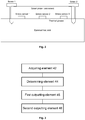
- FIG. 3 is a schematic diagram of a control apparatus for a smart power component according to an embodiment of the present invention.
- the control apparatus for a smart power component may include: an acquiring component 42, configured to acquire the first fitting information and the second fitting information, which is detected by the smart power component, between the smart power component and the external heat sink.
- the first fitting information is the fitting information around the fixed point of the smart power component
- the second fitting information is the fitting information around the non-fixed point of the smart power component.
- Fig. 2 is a schematic diagram illustrating a fit between a smart power component and an external heat sink according to an embodiment of the present invention. As shown in Fig. 2 , the smart power component fits with the external heat sink.
- a stress measuring sensor made of a stress sensitive material is integrated in the smart power component, and the fitting information is detected though the stress measuring sensor.
- Fig. 2 shows that there is a sensor around each fastening screw, and there is a sensor arranged between two fastening screws. The sensor around the fastening screw detects the first fitting information, and the sensor between two screws detects the second fitting information.
- the first fitting information represents whether the fastening screw is too tight or too loose
- the second fitting information represents whether the fit surface between the smart power component and the external heat sink is smooth.
- the stress measuring sensor integrated in the smart power component detects the deformation quantity of the contact surface between the smart power component and the external heat sink, converts the detected deformation quantity to the analog signal, and outputs the analog signal through the pin of the smart power component.
- the smart power component outputs the acquired analog signal to the controller, and then the controller determines whether the fitting information represented by the analog signal satisfies the set condition.
- the smart power component outputs the analog signal to the controller through the pin of this smart power component.
- a form of the analog signal is the voltage signal or the current signal.
- the controller acquires the voltage signal or the current signal, and converts the voltage signal or the current signal to the digital signal, so that the first fitting information and the second fitting information are acquired. That is, the controller acquires the deformation quantity of the contract surface between the smart power component and the external heat sink.
- the acquiring element includes: an acquiring component, configured to acquire the analog signal which is output through a pin of the smart power component, the analog signal including the voltage signal or the current signal, and the analog signal being used for representing the first fitting information and the second fitting information; and a converting component, configured to convert the analog signal to the digital signal to obtain the first fitting information and the second fitting information.
- a determining element 44 is configured to determine whether the first fitting information satisfies the preset condition, and determine determined whether the second fitting information satisfies the preset condition.
- the fitting between the smart power component and the external heat sink needed to be adjusted.
- a first outputting element 46 is configured to output the first prompt information when the first fitting information does not satisfy the preset condition.
- the first prompt information is used for prompting to adjust the fitting around the fixed point.
- a second outputting element 48 is configured to output the second prompt information when the second fitting information does not satisfy the preset condition.
- the second prompt information is used for prompting to adjust the fitting around the non-fixed point.
- the first fitting information and the second fitting information is represented by values, and the preset conditions are thresholds.
- the preset conditions include the too loose threshold and the too tight threshold.
- the prompt warning too tight fit is output.
- the first fitting information is less than the too loose threshold, the prompt warning too loose fit is output.
- the first fitting information satisfies the preset condition, and the second fitting information is between the too loose threshold and the too tight threshold, it is determined that the fitting between the smart power component and the external heat sink is normal.
- the second fitting information is not between the too loose threshold and the too tight threshold, it is prompted that the fitting between the smart power component and the external heat sink is to be adjusted. That is, the determining component is configured to determine that the fit between the smart power component and the external heat sink is normal when it is determined that the first fitting information satisfies the preset condition, and the second fitting information satisfies the preset condition.
- the deformation quantity of the contact surface between the smart power component and the external heat sink is detected by integrating the stress measuring sensor in the smart power component, to determine whether the fit between the smart power component and the external heat sink is normal. When the fit is not normal, prompt information is output to adjust the fit between the smart power component and the external heat sink.
- the storage medium includes a stored program.
- the stored program is configured to perform, when running, the control method for a smart power component in embodiments as mentioned above.
- Another embodiment of the present invention also provides a processor.
- the processor is used for running a program.
- the program is configured to perform, when running, the control method for a smart power component in embodiments as mentioned above.
- the elements described as separate parts may be or may not be separate physically.
- the part shown as the element may be or may not be a physical element, that is to say, it may be in a place or distributed on multiple network elements. Some or all of the elements may be selected according to actual needs to achieve the objectives of the solutions of the embodiments.
- functional elements in the embodiments of the present invention may be integrated into one processing element, or each of the elements may exist alone physically, or two or more elements are integrated into one element.
- the integrated element may be realized in form of hardware or in form of software function element.
- the integrated element When the integrated element is implemented by software function components, and the software function components are sold or used as independent products, they can also be stored in a computer readable storage medium.
- the technical solution of the present invention substantially or the part making a contribution to the conventional art can be embodied in the form of software product; the computer software product is stored in a storage medium, and includes a number of instructions to make a computer apparatus (which may be a personal computer, a server or a network apparatus, etc.) perform all or part of steps of the method in each embodiment of the present invention.
- the storage media include, but not limited to, a USB flash disk, a Read-Only Memory (ROM), a Random Access Memory (RAM), a mobile hard disk, a magnetic disk, a compact disc, and other media capable of storing the program codes.
- a control method and apparatus for a smart power component, a storage medium and a processor provided by the embodiments of the present invention have the following beneficial effect: the technical problem that the poor fit between the smart power component and the external heat sink is not detected is solved.
Landscapes
- Physics & Mathematics (AREA)
- Engineering & Computer Science (AREA)
- General Physics & Mathematics (AREA)
- Microelectronics & Electronic Packaging (AREA)
- Life Sciences & Earth Sciences (AREA)
- Health & Medical Sciences (AREA)
- Chemical & Material Sciences (AREA)
- Analytical Chemistry (AREA)
- Biochemistry (AREA)
- General Health & Medical Sciences (AREA)
- Immunology (AREA)
- Pathology (AREA)
- Manufacturing & Machinery (AREA)
- Thermal Sciences (AREA)
- Emergency Management (AREA)
- Operations Research (AREA)
- Business, Economics & Management (AREA)
- Automation & Control Theory (AREA)
- Power Sources (AREA)
- Cooling Or The Like Of Electrical Apparatus (AREA)
- Charge And Discharge Circuits For Batteries Or The Like (AREA)
Abstract
Description
- The present invention relates to the control field, in particular to a control method and apparatus for a smart power component, a storage medium, and a processor.
- A smart power component is used more and more widely now. Since the smart power component is self-heating during a working process, and the smart power component does not fit well with an external heat sink, a temperature of the smart power component rises too high and even the smart power component burns out. And when the smart power component fits too tight with the external heat sink, a stress generates on the smart power component and an internal chip of the smart power component to cause failures, so a fitting between the smart power component and the external heat sink is very important for the safe and stable operation of the smart power component. However, there is no method known to the inventors to detect whether the fit between the smart power component and the external heat sink is poor.
- As to the above-mentioned problem, no effective solution has been provided yet.
- At least some embodiments of the present invention provide a control method and apparatus for a smart power component, a storage medium and a processor, so as at least to partially solve a technical problem that a poor fit between a smart power component and an external heat sink is not detected.
- In an embodiment of the present invention, a control method for a smart power component is provided, which may include that: first fitting information and second fitting information, which is detected by the smart power component, between a smart power component and an external heat sink is acquired, the first fitting information being the fitting information around a fixed point of the smart power component, and the second fitting information being the fitting information around a non-fixed point of the smart power component; it is determined whether the first fitting information satisfies a preset condition, and it is determined whether the second fitting information satisfies the preset condition; when the first fitting information does not satisfy the preset condition, first prompt information is output, the first prompt information being used for prompting to adjust a fitting around the fixed point; and when the second fitting information does not satisfy the preset condition, second prompt information is output, the second prompt information being used for prompting to adjust a fitting around the non-fixed point.
- In some embodiments, the operation that it is determined whether the first fitting information satisfies the preset condition, and it is determined whether the second fitting information satisfies the preset condition may include that: it is determined whether the first fitting information satisfies the preset condition, and then, when the first fitting information satisfies the preset condition, it is determined whether the second fitting information satisfies the preset condition.
- In some embodiments, the operation that the first fitting information and the second fitting information, which is detected by the smart power component, between the smart power component and the external heat sink is acquired may include that: an analog signal which is output through a pin of the smart power component is acquired, the analog signal including a voltage signal or a current signal, and the analog signal being used for representing the first fitting information and the second fitting information; and the analog signal is converted to a digital signal to obtain the first fitting information and the second fitting information.
- In some embodiments, before the analog signal which is output by the smart power component through the pin is acquired, the control method may further include that: a deformation quantity of a contact surface between the smart power component and the external heat sink is detected through a stress measuring sensor integrated in the smart power component; the detected deformation quantity is converted to the analog signal; and the analog signal is output through the pin.
- In some embodiments, after it is determined whether the first fitting information satisfies the preset condition, and it is determined whether the second fitting information satisfies the preset condition, the control method may further include that: when determining that the first fitting information satisfies the preset condition, and the second fitting information satisfies the preset condition, it is determined that the fit between the smart power component and the external heat sink is normal.
- In another embodiment of the present invention, a control apparatus for a smart power component is also provided, which may include: an acquiring element, configured to acquire the first fitting information and the second fitting information, which is detected by the smart power component, between the smart power component and the external heat sink, the first fitting information being the fitting information around the fixed point of the smart power component, and the second fitting information being the fitting information around the non-fixed point of the smart power component; a determining element, configured to determine whether the first fitting information satisfies a preset condition, and determine whether the second fitting information satisfies the preset condition; a first outputting element, configured to output the first prompt information when the first fitting information does not satisfy the preset condition, the first prompt information being used for prompting to adjust a fitting around the fixed point; and a second outputting element, configured to output the second prompt information when the second fitting information does not satisfy the preset condition, the second prompt information being used for prompting to adjust a fitting around the non-fixed point.
- In some embodiments, the determining element is further configured to determine whether the first fitting information satisfies the preset condition, and then, when the first fitting information satisfies the preset condition, determine whether the second fitting information satisfies the preset condition.
- In some embodiments, the acquiring element includes: an acquiring component, configured to acquire the analog signal which is output through the pin of the smart power component, the analog signal including the voltage signal or the current signal, and the analog signal being used for representing the first fitting information and the second fitting information; and a converting component, configured to convert the analog signal to the digital signal to obtain the first fitting information and the second fitting information.
- In some embodiments, the control apparatus may further include: a determining component, configured to determine that the fit between the smart power component and the external heat sink is normal when determining that the first fitting information satisfies the preset condition, and the second fitting information satisfies the preset condition.
- In another embodiment of the present invention, a storage medium is also provided. The storage medium includes a stored program. The stored program is configured to perform, when running, the control method for a smart power component as mentioned above.
- In another embodiment of the present invention, a processor is also provided, configured to run a program. The program is configured to perform, when running, the control method for a smart power component as mentioned above.
- In the at least some embodiments, the deformation quantity of the contact surface between the smart power component and the external heat sink is detected by integrating the stress measuring sensor in the smart power component, to determine whether the fit between the smart power component and the external heat sink is normal, and when the fit is not normal, prompt information is output to adjust the fit between the smart power component and the external heat sink. Thus, the technical problem known to the inventors that a poor fit between the smart power component and the external heat sink is not detected is solved, and the technical effect of making the fit between the smart power component and the external heat sink normal is achieved.
- The accompanying drawings described here are used for providing further understanding of the present invention, and constitute a part of the present invention. Schematic embodiments of the present invention and description thereof are used for illustrating the present invention and not intended to form an improper limit to the present invention. In the accompanying drawings:
-
Fig. 1 is a flowchart of a control method for a smart power component according to an embodiment of the present invention. -
Fig. 2 is a schematic diagram illustrating a fit between a smart power component and an external heat sink according to an embodiment of the present invention. -
Fig. 3 is a schematic diagram of a control apparatus for a smart power component according to an embodiment of the present invention. - In order to make those skilled in the art understand the solutions of the present invention better, technical solutions in embodiments of the present invention are clearly and completely elaborated below in combination with the accompanying drawings. It is apparent that the described embodiments are a part of the embodiments of the present invention but not all. On the basis of the embodiment of the present invention, all other embodiments obtained on the premise of no creative work of those skilled in the art should fall within the protection scope of the present invention.
- It should be noted that the specification and claims of the application and terms "first", "second", etc. in the foregoing drawings are used for distinguishing similar objects rather than describing a specific sequence or a precedence order. It should be understood that the objects may be exchanged under appropriate circumstances, so that the embodiments of the present invention described here may be implemented in an order different from that described or shown here. In addition, terms "include" and "have" and any variations thereof are intended to cover non-exclusive inclusions. For example, it is not limited for processes, methods, systems, products or devices containing a series of steps or elements to clearly list those steps or elements, and other steps or elements which are not clearly listed or are inherent to these processes, methods, products or devices may be included instead.
- In an embodiment of the present invention, a method embodiment of a control method for a smart power component is provided. It is to be noted that these steps presented in the flowchart of the accompanying drawings can be executed in a computer system like a group of computer executable instructions, and moreover, although a logical sequence is shown in the flowchart, in some cases, the presented or described steps can be performed in a sequence different from that described here.
-
Fig. 1 is a flowchart of a control method for a smart power component according to an embodiment of the present invention. As shown inFig. 1 , the method may include the following steps. - At step 102, first fitting information and second fitting information, which is detected by the smart power component, between a smart power component and an external heat sink is acquired. The first fitting information is the fitting information around a fixed point of the smart power component, and the second fitting information is the fitting information around a non-fixed point of the smart power com ponent.
- Since the smart power component is self-heating during a working process, and the smart power component does not fit well with the external heat sink, a temperature of the smart power component rises too high and even the smart power component burns out. When the component fits too tight with the external heat sink, a stress generates on the smart power component and an internal chip of the smart power component to cause failures; thus a fitting between the smart power component and the external heat sink is very important for the safe and stable operation of the smart power component.
Fig. 2 is a schematic diagram illustrating a fit between a smart power component and an external heat sink according to an embodiment of the present invention. As shown inFig. 2 , the smart power component fits with the external heat sink. - A stress measuring sensor made of a stress sensitive material is integrated in the smart power component, and the fitting information is detected though the stress measuring sensor. There are multiple sensors arranged at different positions of the smart power component, including sensors arranged around the fixed point, and sensors arranged around the non-fixed point. For example,
Fig. 2 shows that there is a sensor (namelystress sensor 1 nearscrew 1 orstress sensor 3 near screw 2) around each fastening screw (namelyscrew 1 or screw 2), and there is a sensor (namely stress sensor 2) arranged between two fastening screws. The sensor around the fastening screw detects the first fitting information, and the sensor between two screws detects the second fitting information. The first fitting information represents whether the fastening screw is too tight or too loose, and the second fitting information represents whether a fit surface between the smart power component and the external heat sink is smooth. - The stress measuring sensor integrated in the smart power component detects a deformation quantity of a contact surface between the smart power component and the external heat sink, converts the detected deformation quantity to an analog signal, and outputs the analog signal through a pin of the smart power component. The smart power component outputs the acquired analog signal to a controller, and then the controller determines whether the fitting information represented by the analog signal satisfies a set condition.
- The smart power component outputs the analog signal to the controller through the pin of this smart power component. A form of the analog signal is a voltage signal or a current signal. The controller acquires the voltage signal or the current signal, and converts the voltage signal or the current signal to a digital signal, so that the first fitting information and the second fitting information is acquired. That is, the controller acquires the deformation quantity of the contract surface between the smart power component and the external heat sink.
- At step 104, it is determined whether the first fitting information satisfies a preset condition, and it is determined whether the second fitting information satisfies a preset condition.
- When the fitting information indicates that the fit between the smart power component and the external heat sink is not normal, the fitting between the smart power component and the external heat sink needed to be adjusted. In some embodiments, it is determined whether the first fitting information satisfies the set condition, and then, when the first fitting information satisfies the preset condition, it is determined whether the second fitting information satisfies the preset condition. That is, when the first fitting information does not satisfy the preset condition, the fitting near the fixed point of the smart power component and the external heat sink is adjusted, and after the fitting near the fixed point of the smart power component and the external heat sink satisfies the set condition, the fitting between the smart power component and the external heat sink is adjusted, so that the fitting between the fixed points satisfies the set condition.
- At step106, when the first fitting information does not satisfy the preset condition, first prompt information is output. The first prompt information is used for prompting to adjust the fitting around the fixed point.
- At step108, when the second fitting information does not satisfy the preset condition, second prompt information is output. The second prompt information is used for prompting to adjust the fitting around the non-fixed point.
- The first fitting information and the second fitting information are represented by values, and the preset conditions are thresholds. The preset conditions include a too loose threshold and a too tight threshold. When the first fitting information is greater than the too tight threshold, a prompt warning too tight fit is output. When the first fitting information is less than the too loose threshold, a prompt warning too loose fit is output. When the first fitting information satisfies the preset condition, and the second fitting information is between the too loose threshold and the too tight threshold, it is determined that the fitting between the smart power component and the external heat sink is normal. When the second fitting information is not between the too loose threshold and the too tight threshold, it is prompted that the fitting between the smart power component and the external heat sink is to be adjusted. That is, when it is determined that the first fitting information satisfies the preset condition, and the second fitting information satisfies the preset condition, it is determined that the fit between the smart power component and the external heat sink is normal.
- In some embodiments, the deformation quantity of the contact surface between the smart power component and the external heat sink is detected by integrating the stress measuring sensor in the smart power component, to determine whether the fit between the smart power component and the external heat sink is normal. When the fit is not normal, prompt information is output to adjust the fit between the smart power component and the external heat sink. Thus, the technical problem known to the inventors that a poor fit between the smart power component and the external heat sink is not detected is solved, and the technical effect of making the fit between the smart power component and the external heat sink normal is achieved.
- The control method for the smart power component may include the following steps.
- At step 301, information of multiple stress sensors is acquired.
- At step 302, a too tight threshold and a too loose threshold are set.
- At step 303, it is determined whether the sensor near the fixed point is greater than the too tight threshold; when the determination result is yes, S304 is performed; when the determination result is no, S305 is performed.
- At step 304, an alarm of too tight fit of the fixed points is performed.
- At step 305, it is determined whether the sensor near the fixed point is less than the too loose threshold; when the determination result is yes, S306 is performed; when the determination result is no, S307 is performed.
- At step 306, an alarm of too loose tight of the fixed points is performed.
- At step 307, it is determined whether the sensor near the fixed point is not in a threshold range; when the determination result is yes, S308 is performed; when the determination result is no, S309 is performed.
- At step 308, an alarm of unsmooth fit surface is performed.
- At step 309, the fit is normal.
- That is, in some embodiments, one too tight threshold and one too loose threshold are set, when the fitting near the fixed point is greater than the too tight threshold, an alarm of too tight fit is output, and the fit tightness is adjusted. When the fitting near the fixed point is less than the too loose threshold, an alarm of too loose fit is output, and the fit tightness is adjusted. When the fitting near the fixed point is between the too loose threshold and the too tight threshold, and the fitting near the non-fixed point is not in the threshold range, an alarm of unsmooth fit surface is output. And when all the fittings are in the threshold range, the fit is normal.
- Another embodiment of the present invention also provides a control apparatus for a smart power component.
Fig. 3 is a schematic diagram of a control apparatus for a smart power component according to an embodiment of the present invention. As shown inFig. 3 , the control apparatus for a smart power component may include:
an acquiringcomponent 42, configured to acquire the first fitting information and the second fitting information, which is detected by the smart power component, between the smart power component and the external heat sink. The first fitting information is the fitting information around the fixed point of the smart power component, and the second fitting information is the fitting information around the non-fixed point of the smart power component. - Since the smart power component is self-heating during a working process, and the smart power component does not fit well with the external heat sink, a temperature of the smart power component rises too high and even the smart power component burns out. When the component fits too tight with the external heat sink, a stress generates on the smart power component and an internal chip of the smart power component to cause failures; thus the fitting between the smart power component and the external heat sink is very important for the safe and stable operation of the smart power component.
Fig. 2 is a schematic diagram illustrating a fit between a smart power component and an external heat sink according to an embodiment of the present invention. As shown inFig. 2 , the smart power component fits with the external heat sink. - A stress measuring sensor made of a stress sensitive material is integrated in the smart power component, and the fitting information is detected though the stress measuring sensor. There are multiple sensors arranged at different positions of the smart power component, including the sensors arranged around the fixed point, and the sensors arranged around the non-fixed point. For example,
Fig. 2 shows that there is a sensor around each fastening screw, and there is a sensor arranged between two fastening screws. The sensor around the fastening screw detects the first fitting information, and the sensor between two screws detects the second fitting information. The first fitting information represents whether the fastening screw is too tight or too loose, and the second fitting information represents whether the fit surface between the smart power component and the external heat sink is smooth. - The stress measuring sensor integrated in the smart power component detects the deformation quantity of the contact surface between the smart power component and the external heat sink, converts the detected deformation quantity to the analog signal, and outputs the analog signal through the pin of the smart power component. The smart power component outputs the acquired analog signal to the controller, and then the controller determines whether the fitting information represented by the analog signal satisfies the set condition.
- The smart power component outputs the analog signal to the controller through the pin of this smart power component. A form of the analog signal is the voltage signal or the current signal. The controller acquires the voltage signal or the current signal, and converts the voltage signal or the current signal to the digital signal, so that the first fitting information and the second fitting information are acquired. That is, the controller acquires the deformation quantity of the contract surface between the smart power component and the external heat sink.
- That is, the acquiring element includes: an acquiring component, configured to acquire the analog signal which is output through a pin of the smart power component, the analog signal including the voltage signal or the current signal, and the analog signal being used for representing the first fitting information and the second fitting information; and a converting component, configured to convert the analog signal to the digital signal to obtain the first fitting information and the second fitting information.
- A determining
element 44 is configured to determine whether the first fitting information satisfies the preset condition, and determine determined whether the second fitting information satisfies the preset condition. - When the fitting information indicates that the fit between the smart power component and the external heat sink is not normal, the fitting between the smart power component and the external heat sink needed to be adjusted. In some embodiments, it is determined whether the first fitting information satisfies the set condition, and then, when the first fitting information satisfies the preset condition, it is determined whether the second fitting information satisfies the preset condition. That is, when the first fitting information does not satisfy the preset condition, the fitting near the fixed point of the smart power component and the external heat sink is adjusted, and after the fitting near the fixed point of the smart power component and the external heat sink satisfies the set condition, the fitting between the smart power component and the external heat sink is adjusted, so that the fitting between the fixed points satisfies the set condition.
- A
first outputting element 46 is configured to output the first prompt information when the first fitting information does not satisfy the preset condition. The first prompt information is used for prompting to adjust the fitting around the fixed point. - A
second outputting element 48 is configured to output the second prompt information when the second fitting information does not satisfy the preset condition. The second prompt information is used for prompting to adjust the fitting around the non-fixed point. - The first fitting information and the second fitting information is represented by values, and the preset conditions are thresholds. The preset conditions include the too loose threshold and the too tight threshold. When the first fitting information is greater than the too tight threshold, the prompt warning too tight fit is output. When the first fitting information is less than the too loose threshold, the prompt warning too loose fit is output. When the first fitting information satisfies the preset condition, and the second fitting information is between the too loose threshold and the too tight threshold, it is determined that the fitting between the smart power component and the external heat sink is normal. When the second fitting information is not between the too loose threshold and the too tight threshold, it is prompted that the fitting between the smart power component and the external heat sink is to be adjusted. That is, the determining component is configured to determine that the fit between the smart power component and the external heat sink is normal when it is determined that the first fitting information satisfies the preset condition, and the second fitting information satisfies the preset condition.
- In some embodiments, the deformation quantity of the contact surface between the smart power component and the external heat sink is detected by integrating the stress measuring sensor in the smart power component, to determine whether the fit between the smart power component and the external heat sink is normal. When the fit is not normal, prompt information is output to adjust the fit between the smart power component and the external heat sink. Thus, the technical problem known to the inventors that the poor fit between the smart power component and the external heat sink is not detected is solved, and the technical effect of making the fit between the smart power component and the external heat sink normal is achieved.
- Another embodiment of the present invention also provides a storage medium. The storage medium includes a stored program. The stored program is configured to perform, when running, the control method for a smart power component in embodiments as mentioned above.
- Another embodiment of the present invention also provides a processor. The processor is used for running a program. The program is configured to perform, when running, the control method for a smart power component in embodiments as mentioned above.
- In the above embodiments of the present invention, descriptions of the embodiments focus on different aspects. A part which is not described in a certain embodiment in detail may refer to the related description of the other embodiments.
- In the several embodiments provided in the application, it should be understood that the technical contents disclosed may be realized in other ways. The embodiment of the apparatus described above is schematic; for example, the division of the elements is a division of logical functions, and there may be other dividing modes during the actual implementation, for example, multiple elements or components may be combined or integrated to another system, or some features may be ignored or are not executed. In addition, coupling, direct coupling, or communication connection shown or discussed may be implemented through indirect coupling or communication connection of some interfaces, elements or components, and may be in an electrical form or other forms.
- The elements described as separate parts may be or may not be separate physically. The part shown as the element may be or may not be a physical element, that is to say, it may be in a place or distributed on multiple network elements. Some or all of the elements may be selected according to actual needs to achieve the objectives of the solutions of the embodiments.
- In addition, functional elements in the embodiments of the present invention may be integrated into one processing element, or each of the elements may exist alone physically, or two or more elements are integrated into one element. The integrated element may be realized in form of hardware or in form of software function element.
- When the integrated element is implemented by software function components, and the software function components are sold or used as independent products, they can also be stored in a computer readable storage medium. Based on this understanding, the technical solution of the present invention substantially or the part making a contribution to the conventional art can be embodied in the form of software product; the computer software product is stored in a storage medium, and includes a number of instructions to make a computer apparatus (which may be a personal computer, a server or a network apparatus, etc.) perform all or part of steps of the method in each embodiment of the present invention. The storage media include, but not limited to, a USB flash disk, a Read-Only Memory (ROM), a Random Access Memory (RAM), a mobile hard disk, a magnetic disk, a compact disc, and other media capable of storing the program codes.
- The above are exemplary embodiments of the present invention; it should be indicated that, on the premise of not departing from the principles of the present invention, those of ordinary skill in the art may also make a number of improvements and supplements, and these improvements and supplements should fall within the protection scope of the present invention.
- To sum up, a control method and apparatus for a smart power component, a storage medium and a processor provided by the embodiments of the present invention have the following beneficial effect: the technical problem that the poor fit between the smart power component and the external heat sink is not detected is solved.
Claims (11)
- A control method for a smart power component, comprising:acquiring first fitting information and second fitting information, which is detected by the smart power component, between a smart power component and an external heat sink, wherein the first fitting information is fitting information around a fixed point of the smart power component, and the second fitting information is fitting information around a non-fixed point of the smart power component;determining whether the first fitting information satisfies a preset condition, and determining whether the second fitting information satisfies the preset condition;outputting first prompt information when the first fitting information does not satisfy the preset condition, wherein the first prompt information is used for prompting to adjust a fitting around the fixed point; andoutputting second prompt information when the second fitting information does not satisfy the preset condition, wherein the second prompt information is used for prompting to adjust a fitting around the non-fixed point.
- The control method as claimed in claim 1, wherein determining whether the first fitting information satisfies the preset condition, and determining whether the second fitting information satisfies the preset condition comprises:
determining whether the first fitting information satisfies the preset condition, and then, when the first fitting information satisfies the preset condition, determining whether the second fitting information satisfies the preset condition. - The control method as claimed in claim 1, wherein acquiring the first fitting information and the second fitting information, which is detected by the smart power component, between the smart power component and the external heat sink comprises:acquiring an analog signal which is output through a pin of the smart power component, wherein the analog signal comprises a voltage signal or a current signal, and the analog signal is used for representing the first fitting information and the second fitting information; andconverting the analog signal to a digital signal to obtain the first fitting information and the second fitting information.
- The control method as claimed in claim 3, wherein before acquiring the analog signal which is output through the pin of the smart power component, the method further comprises:detecting a deformation quantity of a contact surface between the smart power component and the external heat sink through a stress measuring sensor integrated in the smart power component;converting the detected deformation quantity to the analog signal; andoutputting the analog signal through the pin.
- The control method as claimed in claim 1, wherein after determining whether the first fitting information satisfies the preset condition, and determining whether the second fitting information satisfies the preset condition, the method further com prises:
when determining that the first fitting information satisfies the preset condition, and the second fitting information satisfies the preset condition, determining that the fit between the smart power component and the external heat sink is normal. - A control apparatus for a smart power component, comprising:an acquiring element, configured to acquire first fitting information and second fitting information, which is detected by the smart power component, between a smart power component and an external heat sink, wherein the first fitting information is the fitting information around a fixed point of the smart power component, and the second fitting information is the fitting information around a non-fixed point of the smart power component;a determining element, configured to determine whether the first fitting information satisfies a preset condition, and determine whether the second fitting information satisfies the preset condition;a first outputting element, configured to output first prompt information when the first fitting information does not satisfy the preset condition, wherein the first prompt information is used for prompting to adjust a fitting around the fixed point; anda second outputting element, configured to output second prompt information when the second fitting information does not satisfy the preset condition, wherein the second prompt information is used for prompting to adjust a fitting around the non-fixed point.
- The control apparatus as claimed in claim 6, wherein the determining element is further configured to determine whether the first fitting information satisfies the preset condition, and then, when the first fitting information satisfies the preset condition, determine whether the second fitting information satisfies the preset condition.
- The control apparatus as claimed in claim 6, wherein the acquiring element comprises:an acquiring component, configured to acquire an analog signal which is output through a pin of the smart power component, wherein the analog signal comprises a voltage signal or a current signal, and the analog signal is used for representing the first fitting information and the second fitting information; anda converting component, configured to convert the analog signal to a digital signal to obtain the first fitting information and the second fitting information.
- The control apparatus as claimed in claim 6, further comprising:
a determining component, configured to determine that the fit between the smart power component and the external heat sink is normal when determining that the first fitting information satisfies the preset condition and the second fitting information satisfies the preset condition. - A storage medium, comprising a stored program; wherein the stored program is configured to perform, when running, a control method for a smart power component as claimed in any one of claims 1 to 5.
- A processor, for running a program; wherein the program is configured to perform, when running, a control method for a smart power component as claimed in any one of claims 1 to 5.
Applications Claiming Priority (2)
| Application Number | Priority Date | Filing Date | Title |
|---|---|---|---|
| CN201711171425.9A CN108107055B (en) | 2017-11-20 | 2017-11-20 | Control method and device of intelligent power module, storage medium and processor |
| PCT/CN2018/099435 WO2019095740A1 (en) | 2017-11-20 | 2018-08-08 | Control method for smart power module, device, storage medium and processor |
Publications (3)
| Publication Number | Publication Date |
|---|---|
| EP3715778A1 true EP3715778A1 (en) | 2020-09-30 |
| EP3715778A4 EP3715778A4 (en) | 2021-09-01 |
| EP3715778B1 EP3715778B1 (en) | 2022-06-15 |
Family
ID=62207402
Family Applications (1)
| Application Number | Title | Priority Date | Filing Date |
|---|---|---|---|
| EP18878293.2A Active EP3715778B1 (en) | 2017-11-20 | 2018-08-08 | Control method for smart power module, device, storage medium and processor |
Country Status (5)
| Country | Link |
|---|---|
| US (1) | US10806061B2 (en) |
| EP (1) | EP3715778B1 (en) |
| JP (1) | JP7053819B2 (en) |
| CN (1) | CN108107055B (en) |
| WO (1) | WO2019095740A1 (en) |
Families Citing this family (5)
| Publication number | Priority date | Publication date | Assignee | Title |
|---|---|---|---|---|
| CN108107055B (en) | 2017-11-20 | 2019-11-15 | 珠海格力电器股份有限公司 | Control method and device of intelligent power module, storage medium and processor |
| CN109341747A (en) * | 2018-08-14 | 2019-02-15 | 珠海格力电器股份有限公司 | Method and device for judging whether screw is tightened or not and storage medium |
| CN109639125B (en) * | 2018-11-26 | 2019-12-27 | 珠海格力电器股份有限公司 | Control method, device and system for monitoring intelligent power module |
| CN115201257A (en) * | 2021-04-13 | 2022-10-18 | Tcl空调器(中山)有限公司 | Method and device for identifying bonding state of power device and radiator and storage medium |
| CN113188681B (en) * | 2021-04-28 | 2024-02-09 | 宁波奥克斯电气股份有限公司 | An installation fit test method and an installation fit test system |
Family Cites Families (56)
| Publication number | Priority date | Publication date | Assignee | Title |
|---|---|---|---|---|
| GB986031A (en) | 1963-02-04 | 1965-03-17 | Boeing Co | Thermal measuring apparatus |
| US4444994A (en) * | 1982-01-29 | 1984-04-24 | Varo, Inc. | Electrically insulated quick disconnect heat sink |
| CN1037372C (en) * | 1991-07-01 | 1998-02-11 | 中国科学院金属研究所 | Method and device for detecting membrane/base bonding strength |
| FR2701317B1 (en) * | 1993-02-09 | 1995-03-31 | Thomson Csf | Device for measuring the forces exerted on a mechanical part and fixing method. |
| JP2000253674A (en) | 1999-03-03 | 2000-09-14 | Toyota Motor Corp | Inverter control device and electric vehicle control device |
| JP2003110090A (en) | 2001-07-09 | 2003-04-11 | Daikin Ind Ltd | Power modules and air conditioners |
| JP2004165404A (en) * | 2002-11-13 | 2004-06-10 | Yaskawa Electric Corp | Power module with temperature sensor |
| US6808243B1 (en) * | 2003-05-20 | 2004-10-26 | Xerox Corporation | Thermal inkjet print head with blended enable trains |
| US7197406B2 (en) | 2005-06-20 | 2007-03-27 | Lenovo (Singapore) Pte. Ltd | Apparatus, system, and method for identifying structural stress conditions for computer hardware |
| US7518875B2 (en) * | 2006-12-14 | 2009-04-14 | International Business Machines Corporation | Securing heat sinks to a device under test |
| CN101242732B (en) * | 2007-02-08 | 2011-01-05 | 鸿富锦精密工业(深圳)有限公司 | Heat sink combination |
| US7471517B1 (en) * | 2007-08-22 | 2008-12-30 | International Business Machines Corporation | Heat sink retention module having force-adjustable wire modules |
| US7474532B1 (en) * | 2007-08-30 | 2009-01-06 | International Business Machines Corporation | Heat sink restraints for calibrated mating pressure and shock absorption |
| FI120070B (en) * | 2007-10-01 | 2009-06-15 | Kone Corp | Limitation of power supply and protection of the lift |
| CN101980914B (en) * | 2008-04-07 | 2013-03-13 | 三菱电机株式会社 | Control device-integrated electric power steering motor and electric power steering device |
| JP2010056116A (en) | 2008-08-26 | 2010-03-11 | Kiko Kagi Kofun Yugenkoshi | Heat sink test method |
| CN101660703B (en) * | 2008-08-26 | 2012-10-10 | 富准精密工业(深圳)有限公司 | Light emitting diode (LED) lamp |
| CN101749980B (en) * | 2008-12-22 | 2012-12-26 | 富准精密工业(深圳)有限公司 | Radiating fin, radiator and electronic device |
| US8725458B2 (en) | 2008-12-30 | 2014-05-13 | International Business Machines Corporation | Heat sink blockage detector |
| JP5489229B2 (en) | 2010-09-22 | 2014-05-14 | エヌイーシーコンピュータテクノ株式会社 | BGA solder ball overpressure detection mechanism, overpressure detection method, and BGA solder ball overpressure prevention method |
| WO2012101734A1 (en) * | 2011-01-24 | 2012-08-02 | 株式会社日立製作所 | Fluid analysis method and fluid analysis device |
| US8558564B2 (en) | 2011-02-24 | 2013-10-15 | International Business Machines Corporation | Heat spreader flatness detection |
| TWM416031U (en) * | 2011-06-03 | 2011-11-11 | Rong-Gui Lin | LED light device |
| EP2767758A4 (en) * | 2011-10-11 | 2015-06-24 | Posco Led Co Ltd | OPTICAL SEMICONDUCTOR LIGHTING DEVICE |
| SE536262C2 (en) * | 2011-12-20 | 2013-07-23 | Scania Cv Ab | Control device, and method in conjunction with a control device, for controlling a visco coupling |
| JP2013220708A (en) * | 2012-04-16 | 2013-10-28 | Mitsubishi Heavy Ind Ltd | Heat medium heating device, and vehicle air conditioner equipped with the same |
| DE102012012680A1 (en) * | 2012-06-27 | 2014-01-02 | Eva Hartmann | sensor device |
| JP6268509B2 (en) * | 2012-08-10 | 2018-01-31 | パナソニックIpマネジメント株式会社 | Reactor device |
| TW201424556A (en) * | 2012-12-11 | 2014-06-16 | Hon Hai Prec Ind Co Ltd | Heat dissipation system for motherboard |
| DE102012222959B4 (en) * | 2012-12-12 | 2015-04-02 | Semikron Elektronik Gmbh & Co. Kg | Power component device |
| WO2014162773A1 (en) * | 2013-04-01 | 2014-10-09 | 株式会社 マキタ | Cleaner |
| CN104144588B (en) * | 2013-05-06 | 2017-01-25 | 鸿富锦精密工业(深圳)有限公司 | Heat dissipation device and electronic device with same |
| US9538692B2 (en) * | 2013-07-18 | 2017-01-03 | Bae Systems Information And Electronic Systems Integration Inc. | Integrated heat exchanger and power delivery system for high powered electronic modules |
| CN203467058U (en) * | 2013-09-10 | 2014-03-05 | 西门子公司 | Heat radiator of power switch |
| JP2015073012A (en) * | 2013-10-03 | 2015-04-16 | 富士電機株式会社 | Semiconductor device |
| US9188307B2 (en) * | 2013-12-17 | 2015-11-17 | Ephesus Lighting, Inc. | High intensity LED illumination device with automated sensor-based control |
| US9907692B2 (en) * | 2013-12-30 | 2018-03-06 | Zenith Technical Innovations, Llc | Therapeutic thermal compression device |
| US9195281B2 (en) * | 2013-12-31 | 2015-11-24 | Ultravision Technologies, Llc | System and method for a modular multi-panel display |
| CN105579792A (en) * | 2014-09-02 | 2016-05-11 | 阿威德热合金有限公司 | Evaporator section structure and condenser section structure for thermosiphon |
| US20160120071A1 (en) * | 2014-10-27 | 2016-04-28 | Ebullient, Llc | Server with cooling line assembly |
| CN107533347B (en) * | 2015-04-10 | 2020-11-06 | 菲尼克斯电气开发及制造股份有限公司 | Enclosures with Multiple Thermal Surfaces |
| CN106211703A (en) | 2015-04-30 | 2016-12-07 | 佛山市顺德区美的电热电器制造有限公司 | The heat abstractor of power device and the cooling control method of power device |
| CN204578344U (en) * | 2015-05-08 | 2015-08-19 | 深圳市英威腾电气股份有限公司 | Integrated power module and there is pull-down module and the electronic equipment of this integrated power module |
| CN111315112A (en) * | 2015-06-26 | 2020-06-19 | 台达电子工业股份有限公司 | An assembly structure and electronic device for chip power supply |
| JP2017045775A (en) * | 2015-08-24 | 2017-03-02 | 株式会社東芝 | Transmitter and electronic equipment |
| DE102015115421A1 (en) * | 2015-09-14 | 2017-03-16 | Sma Solar Technology Ag | Inverter with a multi-part housing and internal cooling air duct |
| JP6227610B2 (en) | 2015-10-02 | 2017-11-08 | ファナック株式会社 | Cooling device having a function of detecting clogging of radiating fins |
| US10095282B2 (en) * | 2016-06-23 | 2018-10-09 | Dell Products, Lp | Cover for heat sink |
| KR101849140B1 (en) * | 2016-08-23 | 2018-04-17 | 주식회사 로킷 | Fused deposition modeling type 3d printer |
| US9867317B1 (en) * | 2016-08-23 | 2018-01-09 | Juniper Networks, Inc. | Heat sink with mounted power supply |
| CN106370153B (en) * | 2016-08-30 | 2018-11-13 | 北京理工大学 | Contact deformation and contact stress measurements apparatus and method between a kind of metal parts |
| JP6898162B2 (en) * | 2017-06-23 | 2021-07-07 | 矢崎総業株式会社 | Fixed structure of electronic components |
| CN108107055B (en) | 2017-11-20 | 2019-11-15 | 珠海格力电器股份有限公司 | Control method and device of intelligent power module, storage medium and processor |
| JP7155571B2 (en) * | 2018-03-27 | 2022-10-19 | ブラザー工業株式会社 | Electronic component mounter |
| US11219140B2 (en) * | 2018-10-04 | 2022-01-04 | Andrew Wireless Systems Gmbh | Flexible heat pipe cooled assembly |
| US11599176B2 (en) * | 2018-12-31 | 2023-03-07 | Solaredge Technologies Ltd. | Power converter failure detection and prevention |
-
2017
- 2017-11-20 CN CN201711171425.9A patent/CN108107055B/en active Active
-
2018
- 2018-08-08 US US16/627,633 patent/US10806061B2/en active Active
- 2018-08-08 EP EP18878293.2A patent/EP3715778B1/en active Active
- 2018-08-08 WO PCT/CN2018/099435 patent/WO2019095740A1/en not_active Ceased
- 2018-08-08 JP JP2020522781A patent/JP7053819B2/en active Active
Also Published As
| Publication number | Publication date |
|---|---|
| JP7053819B2 (en) | 2022-04-12 |
| EP3715778B1 (en) | 2022-06-15 |
| JP2020527868A (en) | 2020-09-10 |
| US10806061B2 (en) | 2020-10-13 |
| CN108107055A (en) | 2018-06-01 |
| US20200275592A1 (en) | 2020-08-27 |
| EP3715778A4 (en) | 2021-09-01 |
| CN108107055B (en) | 2019-11-15 |
| WO2019095740A1 (en) | 2019-05-23 |
Similar Documents
| Publication | Publication Date | Title |
|---|---|---|
| US10806061B2 (en) | Control method and apparatus for smart power component, storage medium and processor | |
| US10468879B2 (en) | Method and apparatus for parallel operation of packet energy transfer receivers | |
| EP3401636A1 (en) | Battery deformation detection method and device | |
| US10720778B2 (en) | Method for identifying type of cable, power adapter and cable | |
| CN109417304A (en) | A method, related equipment and system for determining a charger | |
| KR20210014906A (en) | Method for controlling wireless transmit power and electronic device including the same | |
| US20170271896A1 (en) | Information processing method, smart battery, terminal and computer storage medium | |
| US20180286609A1 (en) | Power transmission apparatus | |
| CN109149689A (en) | A kind of wireless charging method and device | |
| CN107014508B (en) | Temperature detection method and device, storage medium and processor | |
| CN110134055B (en) | Self-protection heating circuit, beauty instrument, and line fault detection method and device | |
| WO2020062309A1 (en) | Function detection method, apparatus and device for adapter, and storage medium | |
| US10514307B2 (en) | Fault detection apparatus | |
| CN107579563A (en) | Charging abnormity detection method and wearable device | |
| CN204732852U (en) | Domestic food system of processing and electric motor protective device thereof | |
| CN104280687A (en) | Method and system for identifying standard battery | |
| EP3012953A1 (en) | Method of controlling inverter | |
| CN111025184B (en) | Method and device for detecting short circuit of coupler of electric kettle, storage medium and processor | |
| KR20190120527A (en) | System and method for detecting of over-voltage | |
| CN115009050B (en) | Wireless charging protection method and device for vehicle, storage medium and wireless charging vehicle | |
| CN112731840B (en) | Parameter adjusting method and device of electronic equipment and processor | |
| KR20160107775A (en) | System and method for assessing performance of electric energy storage system by using profile | |
| WO2016101475A1 (en) | Charging method and device and computer storage medium | |
| KR20150129575A (en) | Foreign object detection apparatus for wireless charger | |
| KR101676290B1 (en) | Temperature sensor and fire detection system using the same |
Legal Events
| Date | Code | Title | Description |
|---|---|---|---|
| STAA | Information on the status of an ep patent application or granted ep patent |
Free format text: STATUS: THE INTERNATIONAL PUBLICATION HAS BEEN MADE |
|
| PUAI | Public reference made under article 153(3) epc to a published international application that has entered the european phase |
Free format text: ORIGINAL CODE: 0009012 |
|
| STAA | Information on the status of an ep patent application or granted ep patent |
Free format text: STATUS: REQUEST FOR EXAMINATION WAS MADE |
|
| 17P | Request for examination filed |
Effective date: 20191220 |
|
| AK | Designated contracting states |
Kind code of ref document: A1 Designated state(s): AL AT BE BG CH CY CZ DE DK EE ES FI FR GB GR HR HU IE IS IT LI LT LU LV MC MK MT NL NO PL PT RO RS SE SI SK SM TR |
|
| AX | Request for extension of the european patent |
Extension state: BA ME |
|
| DAV | Request for validation of the european patent (deleted) | ||
| DAX | Request for extension of the european patent (deleted) | ||
| A4 | Supplementary search report drawn up and despatched |
Effective date: 20210730 |
|
| RIC1 | Information provided on ipc code assigned before grant |
Ipc: G01B 7/16 20060101AFI20210726BHEP Ipc: G01N 21/95 20060101ALI20210726BHEP Ipc: H01L 23/36 20060101ALI20210726BHEP Ipc: G05D 15/01 20060101ALI20210726BHEP Ipc: G06F 1/00 20060101ALI20210726BHEP |
|
| GRAP | Despatch of communication of intention to grant a patent |
Free format text: ORIGINAL CODE: EPIDOSNIGR1 |
|
| STAA | Information on the status of an ep patent application or granted ep patent |
Free format text: STATUS: GRANT OF PATENT IS INTENDED |
|
| INTG | Intention to grant announced |
Effective date: 20220105 |
|
| GRAS | Grant fee paid |
Free format text: ORIGINAL CODE: EPIDOSNIGR3 |
|
| GRAA | (expected) grant |
Free format text: ORIGINAL CODE: 0009210 |
|
| STAA | Information on the status of an ep patent application or granted ep patent |
Free format text: STATUS: THE PATENT HAS BEEN GRANTED |
|
| AK | Designated contracting states |
Kind code of ref document: B1 Designated state(s): AL AT BE BG CH CY CZ DE DK EE ES FI FR GB GR HR HU IE IS IT LI LT LU LV MC MK MT NL NO PL PT RO RS SE SI SK SM TR |
|
| REG | Reference to a national code |
Ref country code: CH Ref legal event code: EP Ref country code: GB Ref legal event code: FG4D |
|
| REG | Reference to a national code |
Ref country code: IE Ref legal event code: FG4D |
|
| REG | Reference to a national code |
Ref country code: DE Ref legal event code: R096 Ref document number: 602018036882 Country of ref document: DE |
|
| REG | Reference to a national code |
Ref country code: AT Ref legal event code: REF Ref document number: 1498628 Country of ref document: AT Kind code of ref document: T Effective date: 20220715 |
|
| REG | Reference to a national code |
Ref country code: LT Ref legal event code: MG9D |
|
| REG | Reference to a national code |
Ref country code: NL Ref legal event code: MP Effective date: 20220615 |
|
| PG25 | Lapsed in a contracting state [announced via postgrant information from national office to epo] |
Ref country code: SE Free format text: LAPSE BECAUSE OF FAILURE TO SUBMIT A TRANSLATION OF THE DESCRIPTION OR TO PAY THE FEE WITHIN THE PRESCRIBED TIME-LIMIT Effective date: 20220615 Ref country code: NO Free format text: LAPSE BECAUSE OF FAILURE TO SUBMIT A TRANSLATION OF THE DESCRIPTION OR TO PAY THE FEE WITHIN THE PRESCRIBED TIME-LIMIT Effective date: 20220915 Ref country code: LT Free format text: LAPSE BECAUSE OF FAILURE TO SUBMIT A TRANSLATION OF THE DESCRIPTION OR TO PAY THE FEE WITHIN THE PRESCRIBED TIME-LIMIT Effective date: 20220615 Ref country code: HR Free format text: LAPSE BECAUSE OF FAILURE TO SUBMIT A TRANSLATION OF THE DESCRIPTION OR TO PAY THE FEE WITHIN THE PRESCRIBED TIME-LIMIT Effective date: 20220615 Ref country code: GR Free format text: LAPSE BECAUSE OF FAILURE TO SUBMIT A TRANSLATION OF THE DESCRIPTION OR TO PAY THE FEE WITHIN THE PRESCRIBED TIME-LIMIT Effective date: 20220916 Ref country code: FI Free format text: LAPSE BECAUSE OF FAILURE TO SUBMIT A TRANSLATION OF THE DESCRIPTION OR TO PAY THE FEE WITHIN THE PRESCRIBED TIME-LIMIT Effective date: 20220615 Ref country code: BG Free format text: LAPSE BECAUSE OF FAILURE TO SUBMIT A TRANSLATION OF THE DESCRIPTION OR TO PAY THE FEE WITHIN THE PRESCRIBED TIME-LIMIT Effective date: 20220915 |
|
| REG | Reference to a national code |
Ref country code: AT Ref legal event code: MK05 Ref document number: 1498628 Country of ref document: AT Kind code of ref document: T Effective date: 20220615 |
|
| PG25 | Lapsed in a contracting state [announced via postgrant information from national office to epo] |
Ref country code: RS Free format text: LAPSE BECAUSE OF FAILURE TO SUBMIT A TRANSLATION OF THE DESCRIPTION OR TO PAY THE FEE WITHIN THE PRESCRIBED TIME-LIMIT Effective date: 20220615 Ref country code: LV Free format text: LAPSE BECAUSE OF FAILURE TO SUBMIT A TRANSLATION OF THE DESCRIPTION OR TO PAY THE FEE WITHIN THE PRESCRIBED TIME-LIMIT Effective date: 20220615 |
|
| PG25 | Lapsed in a contracting state [announced via postgrant information from national office to epo] |
Ref country code: NL Free format text: LAPSE BECAUSE OF FAILURE TO SUBMIT A TRANSLATION OF THE DESCRIPTION OR TO PAY THE FEE WITHIN THE PRESCRIBED TIME-LIMIT Effective date: 20220615 |
|
| PG25 | Lapsed in a contracting state [announced via postgrant information from national office to epo] |
Ref country code: SM Free format text: LAPSE BECAUSE OF FAILURE TO SUBMIT A TRANSLATION OF THE DESCRIPTION OR TO PAY THE FEE WITHIN THE PRESCRIBED TIME-LIMIT Effective date: 20220615 Ref country code: SK Free format text: LAPSE BECAUSE OF FAILURE TO SUBMIT A TRANSLATION OF THE DESCRIPTION OR TO PAY THE FEE WITHIN THE PRESCRIBED TIME-LIMIT Effective date: 20220615 Ref country code: RO Free format text: LAPSE BECAUSE OF FAILURE TO SUBMIT A TRANSLATION OF THE DESCRIPTION OR TO PAY THE FEE WITHIN THE PRESCRIBED TIME-LIMIT Effective date: 20220615 Ref country code: PT Free format text: LAPSE BECAUSE OF FAILURE TO SUBMIT A TRANSLATION OF THE DESCRIPTION OR TO PAY THE FEE WITHIN THE PRESCRIBED TIME-LIMIT Effective date: 20221017 Ref country code: ES Free format text: LAPSE BECAUSE OF FAILURE TO SUBMIT A TRANSLATION OF THE DESCRIPTION OR TO PAY THE FEE WITHIN THE PRESCRIBED TIME-LIMIT Effective date: 20220615 Ref country code: EE Free format text: LAPSE BECAUSE OF FAILURE TO SUBMIT A TRANSLATION OF THE DESCRIPTION OR TO PAY THE FEE WITHIN THE PRESCRIBED TIME-LIMIT Effective date: 20220615 Ref country code: CZ Free format text: LAPSE BECAUSE OF FAILURE TO SUBMIT A TRANSLATION OF THE DESCRIPTION OR TO PAY THE FEE WITHIN THE PRESCRIBED TIME-LIMIT Effective date: 20220615 Ref country code: AT Free format text: LAPSE BECAUSE OF FAILURE TO SUBMIT A TRANSLATION OF THE DESCRIPTION OR TO PAY THE FEE WITHIN THE PRESCRIBED TIME-LIMIT Effective date: 20220615 |
|
| PG25 | Lapsed in a contracting state [announced via postgrant information from national office to epo] |
Ref country code: PL Free format text: LAPSE BECAUSE OF FAILURE TO SUBMIT A TRANSLATION OF THE DESCRIPTION OR TO PAY THE FEE WITHIN THE PRESCRIBED TIME-LIMIT Effective date: 20220615 Ref country code: IS Free format text: LAPSE BECAUSE OF FAILURE TO SUBMIT A TRANSLATION OF THE DESCRIPTION OR TO PAY THE FEE WITHIN THE PRESCRIBED TIME-LIMIT Effective date: 20221015 |
|
| REG | Reference to a national code |
Ref country code: DE Ref legal event code: R097 Ref document number: 602018036882 Country of ref document: DE |
|
| PG25 | Lapsed in a contracting state [announced via postgrant information from national office to epo] |
Ref country code: MC Free format text: LAPSE BECAUSE OF FAILURE TO SUBMIT A TRANSLATION OF THE DESCRIPTION OR TO PAY THE FEE WITHIN THE PRESCRIBED TIME-LIMIT Effective date: 20220615 Ref country code: AL Free format text: LAPSE BECAUSE OF FAILURE TO SUBMIT A TRANSLATION OF THE DESCRIPTION OR TO PAY THE FEE WITHIN THE PRESCRIBED TIME-LIMIT Effective date: 20220615 |
|
| REG | Reference to a national code |
Ref country code: CH Ref legal event code: PL |
|
| PLBE | No opposition filed within time limit |
Free format text: ORIGINAL CODE: 0009261 |
|
| STAA | Information on the status of an ep patent application or granted ep patent |
Free format text: STATUS: NO OPPOSITION FILED WITHIN TIME LIMIT |
|
| PG25 | Lapsed in a contracting state [announced via postgrant information from national office to epo] |
Ref country code: LU Free format text: LAPSE BECAUSE OF NON-PAYMENT OF DUE FEES Effective date: 20220808 Ref country code: LI Free format text: LAPSE BECAUSE OF NON-PAYMENT OF DUE FEES Effective date: 20220831 Ref country code: DK Free format text: LAPSE BECAUSE OF FAILURE TO SUBMIT A TRANSLATION OF THE DESCRIPTION OR TO PAY THE FEE WITHIN THE PRESCRIBED TIME-LIMIT Effective date: 20220615 Ref country code: CH Free format text: LAPSE BECAUSE OF NON-PAYMENT OF DUE FEES Effective date: 20220831 |
|
| REG | Reference to a national code |
Ref country code: BE Ref legal event code: MM Effective date: 20220831 |
|
| 26N | No opposition filed |
Effective date: 20230316 |
|
| PG25 | Lapsed in a contracting state [announced via postgrant information from national office to epo] |
Ref country code: SI Free format text: LAPSE BECAUSE OF FAILURE TO SUBMIT A TRANSLATION OF THE DESCRIPTION OR TO PAY THE FEE WITHIN THE PRESCRIBED TIME-LIMIT Effective date: 20220615 |
|
| P01 | Opt-out of the competence of the unified patent court (upc) registered |
Effective date: 20230530 |
|
| PG25 | Lapsed in a contracting state [announced via postgrant information from national office to epo] |
Ref country code: IE Free format text: LAPSE BECAUSE OF NON-PAYMENT OF DUE FEES Effective date: 20220808 |
|
| PG25 | Lapsed in a contracting state [announced via postgrant information from national office to epo] |
Ref country code: BE Free format text: LAPSE BECAUSE OF NON-PAYMENT OF DUE FEES Effective date: 20220831 |
|
| PG25 | Lapsed in a contracting state [announced via postgrant information from national office to epo] |
Ref country code: IT Free format text: LAPSE BECAUSE OF FAILURE TO SUBMIT A TRANSLATION OF THE DESCRIPTION OR TO PAY THE FEE WITHIN THE PRESCRIBED TIME-LIMIT Effective date: 20220615 |
|
| PG25 | Lapsed in a contracting state [announced via postgrant information from national office to epo] |
Ref country code: CY Free format text: LAPSE BECAUSE OF FAILURE TO SUBMIT A TRANSLATION OF THE DESCRIPTION OR TO PAY THE FEE WITHIN THE PRESCRIBED TIME-LIMIT Effective date: 20220615 |
|
| PG25 | Lapsed in a contracting state [announced via postgrant information from national office to epo] |
Ref country code: MK Free format text: LAPSE BECAUSE OF FAILURE TO SUBMIT A TRANSLATION OF THE DESCRIPTION OR TO PAY THE FEE WITHIN THE PRESCRIBED TIME-LIMIT Effective date: 20220615 Ref country code: HU Free format text: LAPSE BECAUSE OF FAILURE TO SUBMIT A TRANSLATION OF THE DESCRIPTION OR TO PAY THE FEE WITHIN THE PRESCRIBED TIME-LIMIT; INVALID AB INITIO Effective date: 20180808 |
|
| PG25 | Lapsed in a contracting state [announced via postgrant information from national office to epo] |
Ref country code: MT Free format text: LAPSE BECAUSE OF FAILURE TO SUBMIT A TRANSLATION OF THE DESCRIPTION OR TO PAY THE FEE WITHIN THE PRESCRIBED TIME-LIMIT Effective date: 20220615 |
|
| PG25 | Lapsed in a contracting state [announced via postgrant information from national office to epo] |
Ref country code: BG Free format text: LAPSE BECAUSE OF FAILURE TO SUBMIT A TRANSLATION OF THE DESCRIPTION OR TO PAY THE FEE WITHIN THE PRESCRIBED TIME-LIMIT Effective date: 20220615 |
|
| PG25 | Lapsed in a contracting state [announced via postgrant information from national office to epo] |
Ref country code: BG Free format text: LAPSE BECAUSE OF FAILURE TO SUBMIT A TRANSLATION OF THE DESCRIPTION OR TO PAY THE FEE WITHIN THE PRESCRIBED TIME-LIMIT Effective date: 20220615 |
|
| PGFP | Annual fee paid to national office [announced via postgrant information from national office to epo] |
Ref country code: DE Payment date: 20250819 Year of fee payment: 8 |
|
| PGFP | Annual fee paid to national office [announced via postgrant information from national office to epo] |
Ref country code: GB Payment date: 20250709 Year of fee payment: 8 |
|
| PGFP | Annual fee paid to national office [announced via postgrant information from national office to epo] |
Ref country code: FR Payment date: 20250709 Year of fee payment: 8 |
|
| PG25 | Lapsed in a contracting state [announced via postgrant information from national office to epo] |
Ref country code: TR Free format text: LAPSE BECAUSE OF FAILURE TO SUBMIT A TRANSLATION OF THE DESCRIPTION OR TO PAY THE FEE WITHIN THE PRESCRIBED TIME-LIMIT Effective date: 20220615 |