EP3715253A1 - Seat pan articulation mechanism - Google Patents
Seat pan articulation mechanism Download PDFInfo
- Publication number
- EP3715253A1 EP3715253A1 EP19216870.6A EP19216870A EP3715253A1 EP 3715253 A1 EP3715253 A1 EP 3715253A1 EP 19216870 A EP19216870 A EP 19216870A EP 3715253 A1 EP3715253 A1 EP 3715253A1
- Authority
- EP
- European Patent Office
- Prior art keywords
- link
- end section
- seat pan
- backrest
- multiple holes
- Prior art date
- Legal status (The legal status is an assumption and is not a legal conclusion. Google has not performed a legal analysis and makes no representation as to the accuracy of the status listed.)
- Granted
Links
Images

Classifications
-
- B—PERFORMING OPERATIONS; TRANSPORTING
- B64—AIRCRAFT; AVIATION; COSMONAUTICS
- B64D—EQUIPMENT FOR FITTING IN OR TO AIRCRAFT; FLIGHT SUITS; PARACHUTES; ARRANGEMENT OR MOUNTING OF POWER PLANTS OR PROPULSION TRANSMISSIONS IN AIRCRAFT
- B64D11/00—Passenger or crew accommodation; Flight-deck installations not otherwise provided for
- B64D11/06—Arrangements of seats, or adaptations or details specially adapted for aircraft seats
- B64D11/0639—Arrangements of seats, or adaptations or details specially adapted for aircraft seats with features for adjustment or converting of seats
- B64D11/064—Adjustable inclination or position of seats
-
- B—PERFORMING OPERATIONS; TRANSPORTING
- B60—VEHICLES IN GENERAL
- B60N—SEATS SPECIALLY ADAPTED FOR VEHICLES; VEHICLE PASSENGER ACCOMMODATION NOT OTHERWISE PROVIDED FOR
- B60N2/00—Seats specially adapted for vehicles; Arrangement or mounting of seats in vehicles
- B60N2/02—Seats specially adapted for vehicles; Arrangement or mounting of seats in vehicles the seat or part thereof being movable, e.g. adjustable
- B60N2/22—Seats specially adapted for vehicles; Arrangement or mounting of seats in vehicles the seat or part thereof being movable, e.g. adjustable the back-rest being adjustable
- B60N2/2209—Seats specially adapted for vehicles; Arrangement or mounting of seats in vehicles the seat or part thereof being movable, e.g. adjustable the back-rest being adjustable by longitudinal displacement of the cushion, e.g. back-rest hinged on the bottom to the cushion and linked on the top to the vehicle frame
-
- B—PERFORMING OPERATIONS; TRANSPORTING
- B64—AIRCRAFT; AVIATION; COSMONAUTICS
- B64D—EQUIPMENT FOR FITTING IN OR TO AIRCRAFT; FLIGHT SUITS; PARACHUTES; ARRANGEMENT OR MOUNTING OF POWER PLANTS OR PROPULSION TRANSMISSIONS IN AIRCRAFT
- B64D11/00—Passenger or crew accommodation; Flight-deck installations not otherwise provided for
- B64D11/06—Arrangements of seats, or adaptations or details specially adapted for aircraft seats
- B64D11/0639—Arrangements of seats, or adaptations or details specially adapted for aircraft seats with features for adjustment or converting of seats
-
- B—PERFORMING OPERATIONS; TRANSPORTING
- B60—VEHICLES IN GENERAL
- B60N—SEATS SPECIALLY ADAPTED FOR VEHICLES; VEHICLE PASSENGER ACCOMMODATION NOT OTHERWISE PROVIDED FOR
- B60N2/00—Seats specially adapted for vehicles; Arrangement or mounting of seats in vehicles
- B60N2/02—Seats specially adapted for vehicles; Arrangement or mounting of seats in vehicles the seat or part thereof being movable, e.g. adjustable
- B60N2/0284—Adjustable seat-cushion length
-
- B—PERFORMING OPERATIONS; TRANSPORTING
- B60—VEHICLES IN GENERAL
- B60N—SEATS SPECIALLY ADAPTED FOR VEHICLES; VEHICLE PASSENGER ACCOMMODATION NOT OTHERWISE PROVIDED FOR
- B60N2/00—Seats specially adapted for vehicles; Arrangement or mounting of seats in vehicles
- B60N2/68—Seat frames
- B60N2/682—Joining means
Definitions
- a passenger seat assembly typically has a moveable seat pan that articulates as a passenger adjusts a reclining backrest.
- the articulation of the seat pan corresponds to movement of the backrest in a relationship that avoids sliding and binding sensations from the perspective of the passenger throughout various adjusting movements of a seat assembly.
- a seat pan typically articulates forward as a backrest reclines to a resting position and returns rearward as the backrest is returned to a more upright position.
- the seat pan may also tilt and/or adjust vertically.
- a reclining seat assembly may be limited by airlines or regulators for safety or space efficiency purposes.
- Seat assemblies may be designed with a maximum backrest recline angle that is beyond a limit set according to use in a seating row. In some cases, limits are set well below the reclining ability of a seat assembly. In a seat assembly in which the relationship between backrest movement and seat pan articulation is fixed, limiting the angle by which a backrest can be reclined results in corresponding reduced seat pan articulation, and a reduction of the effectiveness of comfort features of the seat assembly.
- seat pan articulation is linked to backrest adjustment in a relationship that is fixed by a linking mechanism with no effective variability.
- the articulation relationship could likely only be changed to suit needs that may vary by airline preferences by use of replacement parts or custom parts tailored to each application.
- the present invention provides an articulation mechanism for coupling a pivoting backrest to a seat pan frame.
- the mechanism includes a first link or quadrant link having a first end section configured to attach to a pivoting backrest, and a second end section connected to or continuous with the first end section, the second end section having multiple holes.
- a second link has a first end section and a second end section connected together or continuous, the first end section of the second link having at least one hole to be aligned with one of the multiple holes of the second section of the first link, the second end section of the second link configured to pivotally attach to a seat pan frame.
- the second end section of the first link has at least one hole and the first end section of the second link has multiple holes.
- the mechanism may comprise a fastener that pivotally attaches the second link to the first link via the at least one hole of the second link and the aligned one of the multiple holes of the second end section of the first link.
- the multiple holes of the second end section of the first link or of the first end section of the second link are spaced with increasing distance from the first end section of the first link or the second end section of the second link, respectively.
- each of the multiple holes when the first end section of the first link is attached to a pivoting backrest, and the second end section of the second link is pivotally attached to a seat pan frame, each of the multiple holes, when the first and second links are pivotally attached, corresponds to a predetermined ratio of backrest recline to seat pan travel.
- the second end section of the first link is linear.
- the first link includes a linear middle section by which the second end section of the first link is connected to the first end section of the first link; and the second end section of the first link is connected to the middle section of the first link by a bend junction.
- the at least one hole of the first end section of the second link or of the at least one hole in the second end section of the first link is one of multiple holes in the first end section of the second link or of the at least one hole in the second end section of the first link, respectively.
- the multiple holes in the first end section of the second link or in the second end section of the first link are spaced with increasing distance from a terminus of the first end section of the second link or in the second end section of the first link, respectively.
- the first end section of the second link is linear.
- the second link includes a linear middle section by which the second end section of the second link is connected to the first end section of the second link; and the second end section of the second link is connected to the middle section of the second link by a bend junction.
- the second end section of the second link has a ring surrounding a hole for pivotally attaching the second link to a seat pan frame.
- the second end section of the second link has a ring surrounding a hole for pivotally attaching the second link to a seat pan frame, the ring lying in a plane that is parallel to and offset from a plane in which the first end second of the second link extends.
- the inventive concepts disclosed herein are directed to a passenger seat assembly, including at least one frame element, a backrest pivotally attached to the frame element, a seat pan frame movable relative to the frame element, and an articulation mechanism according to the first aspect of the present invention, coupling the seat pan frame to the backrest.
- Embodiments of the present invention can include one or more or any combination of the above aspects, features and configurations.
- the mechanism generally includes two links, which are referenced in the following as a first link or quadrant link, and as a second link or drive link.
- the quadrant link is rigidly attached to the backrest frame, which rotates around its own pivot axis.
- the quadrant link pivots with the backrest frame and generally functions as a lever.
- the drive link is pivotally attached to the seat pan frame, which can translate generally forward and aft with optional tilting motion.
- the quadrant link and drive link attach together to form a pivot.
- the point of attachment between the two links is variable and customizable such that a hole combination is chosen to achieved a predetermined ratio of backrest recline to seat pan travel.
- the quadrant link and drive link may both have multiple holes by which they can be linked together, permitting the relationship between backrest movement and seat pan articulation to be varied by changing the hole combination used.
- one of the two links may have a single hole while the other of the two links may have multiple holes.
- a seat assembly 10 shown in FIG. 1 includes a backrest 12 and a seat pan frame 14 mounted between a pair of frame elements referenced as a right-side spreader 16 and a left-side spreader 18 with respect to the perspective of a seated passenger.
- the seat assembly 10 is shown without the coverings and attachments typically provided for passenger comfort in use.
- an in-use seat assembly would likely include cushions attached to the backrest 12, and a cushioned seat pan attached to the seat pan frame 14.
- Respective pivoting armrests would likely be mounted to the upper ends 20 of the spreaders.
- the backrest 12 is pivotally adjustable relative to the spreaders about a generally horizontal, fixed, laterally-extending pivot axis 22.
- a generally horizontal forward direction 24, partially along which the seat pan frame 14 extends is defined according to the expected perspective of a seated passenger.
- a vertical upward direction 26, partially along which the backrest 12 extends, is defined according to the general disposition of the back of a seated-upright passenger.
- forward movement 30 in an upper portion of the backrest occurs at once with rearward movement 32 of the seat pan frame 14, and vice versa, rearward movement in an upper portion of the backrest occurs at once with forward movement of the seat pan frame.
- the backrest 12 includes a pair of beams, referenced as a right-side beam 34 and a left-side beam 36 pivotally connected to the right-side spreader 16 and a left-side spreader 18, respectively.
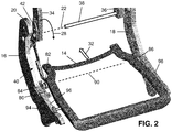
- FIG. 2 shows a right-side articulation mechanism 40, by which a lower end of the right-side beam 34 of the backrest is coupled to the seat pan frame 14.
- a right-side articulation mechanism 40 at the right-side spreader 16 is expressly shown in the drawings and is described in the following.
- a symmetrically similar left-side articulation mechanism at the left-side spreader 18 is understood in a fully assembled and in-use seat assembly.
- the following describes some features without necessarily referring to each as a right-side feature. It is understood such descriptions relate as well to a left-side articulation mechanism by implication.
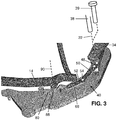
- the lower end of the beam 34 is pivotally connected to the spreader by a connector 38.
- the connector is represented in FIGS. 2-3 as an axle laterally extending along the pivot axis 22 from the left-side spreader 18 and beam 36 to the right-side beam 34 and spreader 16, such that two lateral sides of the seat assembly 10 use a common pivot axis connector 38.
- the connector may be a single side connector 39, at each side of the seat assembly, represented as a pin in FIG. 3 .
- Other pivoting connectors are within the scope of these descriptions.
- a bracket 42 ( FIG. 4 ) is fixedly attached to the lower end of the beam 34 as shown in FIG. 3 , and thus moves with the backrest as the backrest pivots about the pivot axis.
- a lower end 44 of the bracket 42 extends lower than the pivot axis 22, and beyond the pivot axis 22 relative to the beam.
- portions of the beam and backrest that are above the pivot axis 22 translate with some forward movement 30.
- the lower end 44 of the bracket 42 and other attached features that are below the pivot axis 22 translate with rearward movement.
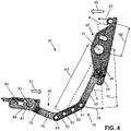
- the articulation mechanism 40 further includes a rigid quadrant link 46 ( FIG. 4 ) having a first end section 48 fixedly attached to the lower end 44 of the bracket 42.
- the quadrant link 46 has a linear middle section 50 extending from the first end section 48 to a linear second end section 52.
- the middle section 50 and second end section 52 are connected together at a bend junction 47.
- Multiple holes are spaced along the second end section 52 of the quadrant link 46 with increasing distance from the first end section 48 and pivot axis 22, which is shown as a crosshair representing the center of rotation of pivoting movements referenced in FIG. 4 .
- the holes are referenced in FIG.
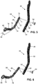
- the articulation mechanism 40 further includes a rigid drive link 66 having a linear first end section 68 ( FIG. 6 ) pivotally attachable to the second end section 52 of the quadrant link 46 at a selected one of the multiple holes by a fastener that permits pivoting movement of the drive link 66 relative to the quadrant link 46.
- a fastener is shown as a link pin 54 in FIGS. 5 and 6 for pivotally attaching the drive link 66 to the quadrant link 46.
- Multiple holes which are referenced as a first hole 71, second hole 72, third hole 73, and fourth hole 74 in FIG. 5 , are spaced along the first end section 68 of the drive link with increasing distance from the terminus 70 of the of first end section.
- any selected hole in the first end section 68 of the drive link 66 can be aligned with any selected hole in second end section 52 of the quadrant link 46 to pivotally connect the drive link 66 to the quadrant link 46 and thereby couple to the seat pan frame to the backrest for coupled movement.
- the drive link 66 is pivotally attached to the quadrant link 46 by the link pin 54 at the aligned first hole 61 of the quadrant link 46 and first hole 71 of the drive link 66 ( FIG. 4 ).
- the drive link 66 has a linear middle section 76 extending from the first end section 68 to a second end section 78, which is pivotally coupled to the seat pan frame 14.
- the first end section 68 and middle section 76 which are connected together at a bend junction 67, share a plane 79 ( FIG. 5 ).
- the second end section 78 extends laterally outward from the plane of the first end section 68 and middle section 76, providing a lateral offset 92 ( FIG. 5 ).
- the seat pan frame 14 is supported at each lateral side by a respective track 80 fixedly attached to the inward lateral side of each spreader.
- a respective track 80 fixedly attached to the inward lateral side of each spreader.
- an axle 82 connected to the laterally outer side of the seat pan frame 14 extends toward the track 80.
- a roller 84 rotationally mounted on the axle 82 engages the track 80 and is rollable along the track.
- the right-side axle 82 and roller 84 are aligned with the left-side roller 86 ( FIG. 2 ) and corresponding axle along a laterally extending travel axis 90, which moves accordingly with the seat pan frame 14.
- the seat pan frame 14 is movably attached to each spreader for both pivoting rotational movement about the corresponding axle and translational movement along the corresponding track.
- the track 80 extends generally horizontally thereby facilitating forward and rearward movement 32 of the seat pan frame 14.
- the track 80 may be inclined forward as shown in FIG. 5 such that rearward movement 32 of the roller 84 along the track lowers the rear of the seat pan frame 14 according to the angle of inclination.
- the second end section 78 of the drive link 66 is shown as having a ring 88 with a central hole for pivotally coupling the drive link to the seat pan frame 14 by way of the axle 82.
- the ring 88 lies in a plane that is parallel to the shared plane 79 of the first end section 68 and middle section 76.
- the ring 88 is spaced laterally outward relative to the first end section 68 and middle section 76 by the lateral offset 92 ( FIG. 5 ) provided by the second end section 78 ( FIG. 5 ) to reach the axle 82, which extends from the seat pan frame 14 and through the ring 88.
- the drive link 66 is pulled rearward by the quadrant link 46, and thus pulls the seat pan frame 14 rearward as the roller 84 travels along the track 80.
- the drive link 66 is pushed forward by the quadrant link 46, and thus pushes the seat pan frame 14 forward.
- the quadrant link 46 is fixedly attached to the bracket 42 and is thus fixed relative to the beam 34 of the backrest.
- the quadrant link 46 thus moves by simply pivoting around the pivot axis 22 as represented in FIG. 4 .
- the drive link 66 is pivotally connected to each of the quadrant link 46 and the axle 82 on which the seat pan frame 14 travels. Thus, the drive link 66 both translates and rotates as the articulation mechanism 40 functions.
- the selection of the holes by which the drive link 66 is pivotally attached to the quadrant link 46 sets the relationship between backrest movement and seat pan articulation. This can be understood for example in view of FIG. 4 .
- the amount of movement or distance of arcuate travel of any point along the bracket 42 and backrest 12 is proportional to the angle A and a radius by which the point is spaced from the pivot axis 22.
- Another hole in the second end section 52 further from the pivot axis 22 and referenced as the third hole 63 is distanced from the pivot axis 22 by a radius R3 that is greater than R1, and accordingly travels approximately rearward along an arc of travel proportional to the radius R3 and the angle A.
- the first hole 61 and third hole 63 travel by different amounts as the backrest pivots by any given angle as represented by the bracket 42 in FIG. 4 .
- each particular one of the multiple holes in the second end section 52 of the quadrant link 46 corresponds to a particular predetermined ratio of backrest recline to seat pan travel.
- the quadrant link 46 and drive link 66 are depicted in exploded perspective views in FIGS. 5-6 to show that the holes by which the drive link is pivotally attached to the quadrant link can be selected to set the relationship between backrest movement and seat pan articulation.
- the first hole 61 of the quadrant link 46 is aligned with the first hole 71 of the drive link, for pivotal attachment by the link pin 54.
- the third hole 63 of the quadrant link 46 is aligned with the first hole 71 of the drive link, for pivotal attachment by the link pin 54.
- the link pin 54 is received by the selected aligned holes and engages the drive link and quadrant link.
- FIGS. 5 and 6 provide different correspondence of the translational movement of the backrest 12 relative to the translational movement of the seat pan frame 14 according to the different radii R1 and R3 of the first hole 61 and second hole 71 of the quadrant link 46 relative to the pivot axis 22 ( FIG. 4 ).
- the articulation mechanism 40 provides variability to articulating seats.
- the angle of the seat pan frame 14 optionally adjusts by controlled rotation about the travel axis 90, for example as the seat pan frame 14 moves forward or rearward.
- the angle of the seat pan frame 14 depends on what structure forward of the travel axis 90 supports forward portions of the seat pan frame 14.
- the seat pan frame 14 is further supported at each lateral side forward of the travel axis 90 by respective top edges of the spreaders.
- a guide wheel 94 extends from the seat pan frame 14 and rolls upon the guide edge 96 of the corresponding spreader. The guide wheels 94 track along the guide edges 96 of the spreaders, so the shapes of the spreaders determine the seat pan angle.
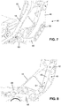
- FIGS. 7 and 8 show the right-side spreader 16 as skeletonized as may be preferred in use in an aircraft to minimize weight.
- the spreader 16 is shown in FIG. 7 as having a respective articulation mechanism 40 mounted on each side, representing the spreader 16 as a shared structural support for adjacent seats in a seating row.
- the drawings generally reference movements of the articulation mechanism 40 correlated with the backrest 12 pivoting in the first rotational direction 28 as referenced in FIG. 1 , in which forward movement 30 in an upper portion of the backrest 12 occurs at once with rearward movement 32 of the seat pan frame 14. It is understood that the referenced movements of the articulation mechanism 40 will reverse when the backrest 12 returns rearward and the seat pan frame 14 travels forward.
- An articulation mechanism permit the relationship between backrest adjustment and seat pan articulation to be varied conveniently with a set of universal or widely applicable parts.
- the articulation of a seat assembly can be varied according to how the seat is to be used, for example according to the available space and corresponding recline limits dictated for various seating section in an aircraft. Different configurations of the articulation mechanism can be set for different areas of a passenger cabin, permitting one seating assembly model to suit various uses.
- the articulation relationship provided by the articulation mechanism can be various by repositioning the link pin relative to either or both hole sets of the quadrant link and drive link.
Landscapes
- Engineering & Computer Science (AREA)
- Aviation & Aerospace Engineering (AREA)
- Transportation (AREA)
- Mechanical Engineering (AREA)
- Chairs For Special Purposes, Such As Reclining Chairs (AREA)
- Seats For Vehicles (AREA)
Abstract
Description
- A passenger seat assembly, such as those used in aircraft, typically has a moveable seat pan that articulates as a passenger adjusts a reclining backrest. Preferably, the articulation of the seat pan corresponds to movement of the backrest in a relationship that avoids sliding and binding sensations from the perspective of the passenger throughout various adjusting movements of a seat assembly. A seat pan typically articulates forward as a backrest reclines to a resting position and returns rearward as the backrest is returned to a more upright position. The seat pan may also tilt and/or adjust vertically.
- The range of use of a reclining seat assembly may be limited by airlines or regulators for safety or space efficiency purposes. Seat assemblies may be designed with a maximum backrest recline angle that is beyond a limit set according to use in a seating row. In some cases, limits are set well below the reclining ability of a seat assembly. In a seat assembly in which the relationship between backrest movement and seat pan articulation is fixed, limiting the angle by which a backrest can be reclined results in corresponding reduced seat pan articulation, and a reduction of the effectiveness of comfort features of the seat assembly.
- In some existing seat assemblies, seat pan articulation is linked to backrest adjustment in a relationship that is fixed by a linking mechanism with no effective variability. In such conventional seat assemblies, the articulation relationship could likely only be changed to suit needs that may vary by airline preferences by use of replacement parts or custom parts tailored to each application.
- Accordingly, an improved seat pan articulation that permits the relationship between backrest adjustment and seat pan articulation to be varied conveniently with a set of universal or widely applicable parts is needed.
- To achieve the foregoing and other advantages, according to a first aspect, the present invention provides an articulation mechanism for coupling a pivoting backrest to a seat pan frame. The mechanism includes a first link or quadrant link having a first end section configured to attach to a pivoting backrest, and a second end section connected to or continuous with the first end section, the second end section having multiple holes. A second link has a first end section and a second end section connected together or continuous, the first end section of the second link having at least one hole to be aligned with one of the multiple holes of the second section of the first link, the second end section of the second link configured to pivotally attach to a seat pan frame. Alternatively, the second end section of the first link has at least one hole and the first end section of the second link has multiple holes. The mechanism may comprise a fastener that pivotally attaches the second link to the first link via the at least one hole of the second link and the aligned one of the multiple holes of the second end section of the first link.
- In some embodiments, the multiple holes of the second end section of the first link or of the first end section of the second link are spaced with increasing distance from the first end section of the first link or the second end section of the second link, respectively.
- In some embodiments, when the first end section of the first link is attached to a pivoting backrest, and the second end section of the second link is pivotally attached to a seat pan frame, each of the multiple holes, when the first and second links are pivotally attached, corresponds to a predetermined ratio of backrest recline to seat pan travel.
- In some embodiments, the second end section of the first link is linear.
- In some embodiments, the first link includes a linear middle section by which the second end section of the first link is connected to the first end section of the first link; and the second end section of the first link is connected to the middle section of the first link by a bend junction.
- In some embodiments, the at least one hole of the first end section of the second link or of the at least one hole in the second end section of the first link is one of multiple holes in the first end section of the second link or of the at least one hole in the second end section of the first link, respectively.
- In some embodiments, the multiple holes in the first end section of the second link or in the second end section of the first link are spaced with increasing distance from a terminus of the first end section of the second link or in the second end section of the first link, respectively.
- In some embodiments, the first end section of the second link is linear.
- In some embodiments, the second link includes a linear middle section by which the second end section of the second link is connected to the first end section of the second link; and the second end section of the second link is connected to the middle section of the second link by a bend junction.
- In some embodiments, the second end section of the second link has a ring surrounding a hole for pivotally attaching the second link to a seat pan frame.
- In some embodiments, the second end section of the second link has a ring surrounding a hole for pivotally attaching the second link to a seat pan frame, the ring lying in a plane that is parallel to and offset from a plane in which the first end second of the second link extends.
- According to a second aspect, the inventive concepts disclosed herein are directed to a passenger seat assembly, including at least one frame element, a backrest pivotally attached to the frame element, a seat pan frame movable relative to the frame element, and an articulation mechanism according to the first aspect of the present invention, coupling the seat pan frame to the backrest.
- Embodiments of the present invention can include one or more or any combination of the above aspects, features and configurations.
- The present invention may be better understood when consideration is given to the following detailed description thereof. Such description makes reference to the included drawings, which are not necessarily to scale, and in which some features may be exaggerated, and some features may be omitted or may be represented schematically in the interest of clarity. Like reference numbers in the drawings may represent and refer to the same or similar element, feature, or function. In the drawings:
-
FIG. 1 is a perspective view of a reclining seat assembly according to the present invention; -
FIG. 2 is another perspective view of lower portions of the reclining seat assembly ofFIG. 1 ; -
FIG. 3 is an enlarged perspective view, taken from underneath the seat assembly ofFIG. 1 , showing an articulation mechanism according to the present invention; -
FIG. 4 is a side view of the articulation mechanism ofFIG. 3 , showing the quadrant link, drive link, bracket, and track without other components of the seat assembly; -
FIG. 5 is a perspective view of the quadrant link and drive link aligned for a first articulation relationship between seatback adjustment and seat pan frame articulation; -
FIG. 6 is a perspective view of the quadrant link and drive link aligned for a second articulation relationship between seatback adjustment and seat pan frame articulation; -
FIG. 7 is a perspective view of the articulation mechanism ofFIG. 3 installed on a seat assembly with a skeletonized spreader; and -
FIG. 8 is a side view of the articulation mechanism and seat assembly ofFIG. 7 . - The description set forth below in connection with the appended drawings is intended to be a description of various, illustrative embodiments of the present invention. Specific features and functionalities are described in connection with each illustrative embodiment; however, it will be apparent to those skilled in the art that the disclosed embodiments may be practiced without each of those specific features and functionalities. The aspects, features and functions described below in connection with one embodiment are intended to be applicable to the other embodiments described below except where expressly stated or where an aspect, feature or function is incompatible with an embodiment.
- These descriptions detail an articulation adjustment mechanism that facilitates seat pan articulation to be varied relative to backrest movement in a reclining seat. One such mechanism can be installed at each lateral side of an articulating passenger seat, for example, symmetrically. The mechanism generally includes two links, which are referenced in the following as a first link or quadrant link, and as a second link or drive link. The quadrant link is rigidly attached to the backrest frame, which rotates around its own pivot axis. Thus, the quadrant link pivots with the backrest frame and generally functions as a lever. The drive link is pivotally attached to the seat pan frame, which can translate generally forward and aft with optional tilting motion. The quadrant link and drive link attach together to form a pivot. The point of attachment between the two links is variable and customizable such that a hole combination is chosen to achieved a predetermined ratio of backrest recline to seat pan travel. In some embodiments, the quadrant link and drive link may both have multiple holes by which they can be linked together, permitting the relationship between backrest movement and seat pan articulation to be varied by changing the hole combination used. In other embodiments, one of the two links may have a single hole while the other of the two links may have multiple holes. Upon installation, or when the articulation relationship is to be changed, the drive link is attached to the quadrant link, for example, by use of a fastener such as a link pin, at a hole combination that achieves the desired seat pan articulation.
- A
seat assembly 10 shown inFIG. 1 includes abackrest 12 and aseat pan frame 14 mounted between a pair of frame elements referenced as a right-side spreader 16 and a left-side spreader 18 with respect to the perspective of a seated passenger. Theseat assembly 10 is shown without the coverings and attachments typically provided for passenger comfort in use. For example, an in-use seat assembly would likely include cushions attached to thebackrest 12, and a cushioned seat pan attached to theseat pan frame 14. Respective pivoting armrests would likely be mounted to theupper ends 20 of the spreaders. These and other components of a passenger seat or seating row, such as a tray at the rear of the backrest, are not illustrated to permit view of the inventive features and benefits. - Each spreader in use would likely be supported by legs or beams connected directly or indirectly to the floor or other fixed structure of a passenger vehicle such as an aircraft. The spreaders together serve as a frame of reference treated as fixed or stationary in these descriptions. The
backrest 12 is pivotally adjustable relative to the spreaders about a generally horizontal, fixed, laterally-extendingpivot axis 22. For descriptive purposes, a generally horizontalforward direction 24, partially along which theseat pan frame 14 extends, is defined according to the expected perspective of a seated passenger. A verticalupward direction 26, partially along which thebackrest 12 extends, is defined according to the general disposition of the back of a seated-upright passenger. - As the
backrest 12 pivots in a firstrotational direction 28 about thepivot axis 22,forward movement 30 in an upper portion of the backrest occurs at once withrearward movement 32 of theseat pan frame 14, and vice versa, rearward movement in an upper portion of the backrest occurs at once with forward movement of the seat pan frame. This corresponds, for example, to a passenger adjusting theseat assembly 10 from a reclined resting position to a more upright position, and vice versa, to a passenger adjusting the seat assembly from upright to reclined. Althoughforward movement 30 of thebackrest 12 and correspondingrearward movement 32 of theseat pan frame 14 are expressly referenced for clarity in the drawings, it is understood that the backrest can be pivoted about thepivot axis 22 in reverse to the firstrotational direction 28, with the backrest returning rearward and theseat pan frame 14 traveling forward. Thebackrest 12 includes a pair of beams, referenced as a right-side beam 34 and a left-side beam 36 pivotally connected to the right-side spreader 16 and a left-side spreader 18, respectively. -
FIG. 2 shows a right-side articulation mechanism 40, by which a lower end of the right-side beam 34 of the backrest is coupled to theseat pan frame 14. To continue the example ofFIG. 1 ,rearward movement 32 of theseat pan frame 14 occurs as thebackrest 12 pivots in the firstrotational direction 28 about thepivot axis 22. A right-side articulation mechanism 40 at the right-side spreader 16 is expressly shown in the drawings and is described in the following. A symmetrically similar left-side articulation mechanism at the left-side spreader 18 is understood in a fully assembled and in-use seat assembly. For brevity, the following describes some features without necessarily referring to each as a right-side feature. It is understood such descriptions relate as well to a left-side articulation mechanism by implication. - As shown in
FIGS. 2-3 , the lower end of thebeam 34 is pivotally connected to the spreader by aconnector 38. The connector is represented inFIGS. 2-3 as an axle laterally extending along thepivot axis 22 from the left-side spreader 18 andbeam 36 to the right-side beam 34 andspreader 16, such that two lateral sides of theseat assembly 10 use a commonpivot axis connector 38. Alternatively, the connector may be asingle side connector 39, at each side of the seat assembly, represented as a pin inFIG. 3 . Other pivoting connectors are within the scope of these descriptions. - A bracket 42 (
FIG. 4 ) is fixedly attached to the lower end of thebeam 34 as shown inFIG. 3 , and thus moves with the backrest as the backrest pivots about the pivot axis. Alower end 44 of thebracket 42 extends lower than thepivot axis 22, and beyond thepivot axis 22 relative to the beam. As thebeam 34 andbackrest 12 pivot in the firstrotational direction 28, portions of the beam and backrest that are above thepivot axis 22 translate with someforward movement 30. Simultaneously, thelower end 44 of thebracket 42 and other attached features that are below thepivot axis 22 translate with rearward movement. - The
articulation mechanism 40 further includes a rigid quadrant link 46 (FIG. 4 ) having afirst end section 48 fixedly attached to thelower end 44 of thebracket 42. Thequadrant link 46 has a linearmiddle section 50 extending from thefirst end section 48 to a linearsecond end section 52. Themiddle section 50 andsecond end section 52 are connected together at a bend junction 47. Multiple holes are spaced along thesecond end section 52 of thequadrant link 46 with increasing distance from thefirst end section 48 andpivot axis 22, which is shown as a crosshair representing the center of rotation of pivoting movements referenced inFIG. 4 . The holes are referenced inFIG. 4 , proceeding along thesecond end section 52 from themiddle section 50 with increasing distance from thepivot axis 22, as afirst hole 61,second hole 62,third hole 63, andfourth hole 64. Any number of thru-holes, spacing between holes, and predetermined distances from the backrest pivot axis are possible. - The
articulation mechanism 40 further includes arigid drive link 66 having a linear first end section 68 (FIG. 6 ) pivotally attachable to thesecond end section 52 of thequadrant link 46 at a selected one of the multiple holes by a fastener that permits pivoting movement of thedrive link 66 relative to thequadrant link 46. For example, a fastener is shown as alink pin 54 inFIGS. 5 and 6 for pivotally attaching thedrive link 66 to thequadrant link 46. Multiple holes, which are referenced as afirst hole 71,second hole 72,third hole 73, andfourth hole 74 inFIG. 5 , are spaced along thefirst end section 68 of the drive link with increasing distance from theterminus 70 of the of first end section. Any selected hole in thefirst end section 68 of thedrive link 66 can be aligned with any selected hole insecond end section 52 of thequadrant link 46 to pivotally connect thedrive link 66 to thequadrant link 46 and thereby couple to the seat pan frame to the backrest for coupled movement. InFIG. 3 , thedrive link 66 is pivotally attached to thequadrant link 46 by thelink pin 54 at the alignedfirst hole 61 of thequadrant link 46 andfirst hole 71 of the drive link 66 (FIG. 4 ). - The
drive link 66 has a linearmiddle section 76 extending from thefirst end section 68 to asecond end section 78, which is pivotally coupled to theseat pan frame 14. Thefirst end section 68 andmiddle section 76, which are connected together at a bend junction 67, share a plane 79 (FIG. 5 ). Thesecond end section 78 extends laterally outward from the plane of thefirst end section 68 andmiddle section 76, providing a lateral offset 92 (FIG. 5 ). - The
seat pan frame 14 is supported at each lateral side by arespective track 80 fixedly attached to the inward lateral side of each spreader. As shown in particular for the right-side spreader 16 inFIGS. 2 and4 , anaxle 82 connected to the laterally outer side of theseat pan frame 14 extends toward thetrack 80. Aroller 84 rotationally mounted on theaxle 82 engages thetrack 80 and is rollable along the track. The right-side axle 82 androller 84 are aligned with the left-side roller 86 (FIG. 2 ) and corresponding axle along a laterally extendingtravel axis 90, which moves accordingly with theseat pan frame 14. Thus, theseat pan frame 14 is movably attached to each spreader for both pivoting rotational movement about the corresponding axle and translational movement along the corresponding track. Thetrack 80 extends generally horizontally thereby facilitating forward andrearward movement 32 of theseat pan frame 14. Thetrack 80 may be inclined forward as shown inFIG. 5 such thatrearward movement 32 of theroller 84 along the track lowers the rear of theseat pan frame 14 according to the angle of inclination. - The
second end section 78 of thedrive link 66 is shown as having aring 88 with a central hole for pivotally coupling the drive link to theseat pan frame 14 by way of theaxle 82. Thering 88 lies in a plane that is parallel to the shared plane 79 of thefirst end section 68 andmiddle section 76. Thering 88 is spaced laterally outward relative to thefirst end section 68 andmiddle section 76 by the lateral offset 92 (FIG. 5 ) provided by the second end section 78 (FIG. 5 ) to reach theaxle 82, which extends from theseat pan frame 14 and through thering 88. As thequadrant link 46 pivots about thepivot axis 22 with forward adjusting movement of thebackrest 12, thedrive link 66 is pulled rearward by thequadrant link 46, and thus pulls theseat pan frame 14 rearward as theroller 84 travels along thetrack 80. Conversely, when thequadrant link 46 pivots about thepivot axis 22 with rearward adjusting movement of thebackrest 12, thedrive link 66 is pushed forward by thequadrant link 46, and thus pushes theseat pan frame 14 forward. - The
quadrant link 46 is fixedly attached to thebracket 42 and is thus fixed relative to thebeam 34 of the backrest. Thequadrant link 46 thus moves by simply pivoting around thepivot axis 22 as represented inFIG. 4 . Thedrive link 66 is pivotally connected to each of thequadrant link 46 and theaxle 82 on which theseat pan frame 14 travels. Thus, thedrive link 66 both translates and rotates as thearticulation mechanism 40 functions. - The selection of the holes by which the
drive link 66 is pivotally attached to thequadrant link 46 sets the relationship between backrest movement and seat pan articulation. This can be understood for example in view ofFIG. 4 . As the backrest pivots an angle A in a firstrotational direction 28 about thepivot axis 22, generallyforward movement 30 occurs in all portions of thebracket 42 and backrest that are above thepivot axis 22. The amount of movement or distance of arcuate travel of any point along thebracket 42 andbackrest 12 is proportional to the angle A and a radius by which the point is spaced from thepivot axis 22. For example, the upper end of thebracket 42 referenced inFIG. 4 at a radius RB travels approximately forward along an arc of travel proportional to the radius RB and the angle A (arc length = radius × angle). This is perceived by a seated passenger as forward movement 30 (FIG. 1 ) in an upper portion of thebackrest 12 by pivoting movement of the backrest around thepivot axis 22 by the angle A (FIG. 4 ). - As the
backrest 12 pivots about thepivot axis 22 by the angle A, generallyrearward movement 32 occurs in all points along thebracket 42 and quadrant link 46 that are below thepivot axis 22. Each such point travels along an arc proportional to its radius from thepivot axis 22 and the angle A. For example, the hole in thesecond end section 52 nearest thepivot axis 22 and referenced as thefirst hole 61 is distanced from thepivot axis 22 by a radius R1 and accordingly travels approximately rearward along an arc of travel proportional to the radius R1 and the angle A. Another hole in thesecond end section 52 further from thepivot axis 22 and referenced as thethird hole 63 is distanced from thepivot axis 22 by a radius R3 that is greater than R1, and accordingly travels approximately rearward along an arc of travel proportional to the radius R3 and the angle A. Thefirst hole 61 andthird hole 63 travel by different amounts as the backrest pivots by any given angle as represented by thebracket 42 inFIG. 4 . Thus, each particular one of the multiple holes in thesecond end section 52 of thequadrant link 46 corresponds to a particular predetermined ratio of backrest recline to seat pan travel. - The
quadrant link 46 and drivelink 66 are depicted in exploded perspective views inFIGS. 5-6 to show that the holes by which the drive link is pivotally attached to the quadrant link can be selected to set the relationship between backrest movement and seat pan articulation. InFIG. 5 , thefirst hole 61 of thequadrant link 46 is aligned with thefirst hole 71 of the drive link, for pivotal attachment by thelink pin 54. InFIG. 6 , thethird hole 63 of thequadrant link 46 is aligned with thefirst hole 71 of the drive link, for pivotal attachment by thelink pin 54. To pivotally attach thedrive link 66 to the quadrant link 47, thelink pin 54 is received by the selected aligned holes and engages the drive link and quadrant link. - Thus, the linking arrangements of
FIGS. 5 and 6 provide different correspondence of the translational movement of thebackrest 12 relative to the translational movement of theseat pan frame 14 according to the different radii R1 and R3 of thefirst hole 61 andsecond hole 71 of thequadrant link 46 relative to the pivot axis 22 (FIG. 4 ). As any selected hole infirst end section 68 of thedrive link 66 can be aligned with any selected hole insecond end section 52 of thequadrant link 46 to pivotally connect the drive link to thequadrant link 46, thearticulation mechanism 40 provides variability to articulating seats. - Due to alignment of the right-
side axle 82 and roller 84 (FIG. 2 ) with the left-side roller 86 (FIG. 4 ) and corresponding axle, the angle of theseat pan frame 14 optionally adjusts by controlled rotation about thetravel axis 90, for example as theseat pan frame 14 moves forward or rearward. The angle of theseat pan frame 14 depends on what structure forward of thetravel axis 90 supports forward portions of theseat pan frame 14. In the illustrated embodiment, theseat pan frame 14 is further supported at each lateral side forward of thetravel axis 90 by respective top edges of the spreaders. At each lateral side, aguide wheel 94 extends from theseat pan frame 14 and rolls upon theguide edge 96 of the corresponding spreader. Theguide wheels 94 track along the guide edges 96 of the spreaders, so the shapes of the spreaders determine the seat pan angle. -
FIGS. 7 and 8 show the right-side spreader 16 as skeletonized as may be preferred in use in an aircraft to minimize weight. Thespreader 16 is shown inFIG. 7 as having arespective articulation mechanism 40 mounted on each side, representing thespreader 16 as a shared structural support for adjacent seats in a seating row. - The drawings generally reference movements of the
articulation mechanism 40 correlated with thebackrest 12 pivoting in the firstrotational direction 28 as referenced inFIG. 1 , in whichforward movement 30 in an upper portion of thebackrest 12 occurs at once withrearward movement 32 of theseat pan frame 14. It is understood that the referenced movements of thearticulation mechanism 40 will reverse when thebackrest 12 returns rearward and theseat pan frame 14 travels forward. - An articulation mechanism according to the descriptions above permit the relationship between backrest adjustment and seat pan articulation to be varied conveniently with a set of universal or widely applicable parts. The articulation of a seat assembly can be varied according to how the seat is to be used, for example according to the available space and corresponding recline limits dictated for various seating section in an aircraft. Different configurations of the articulation mechanism can be set for different areas of a passenger cabin, permitting one seating assembly model to suit various uses. The articulation relationship provided by the articulation mechanism can be various by repositioning the link pin relative to either or both hole sets of the quadrant link and drive link.
- While the foregoing description provides embodiments of the invention by way of example only, it is envisioned that other embodiments that are within the scope of the present invention as defined by the appended claims may perform similar functions and/or achieve similar results.
Claims (13)
- An articulation mechanism (40) for coupling a pivoting backrest (12) to a traveling seat pan frame (14), the mechanism (40) comprising:a first link (46) having a first end section (48) configured to attach to the pivoting backrest (12), and a second end section (52) connected to the first end section (48), the second end section (52) having at least one hole (61, 62, 63, 64), anda second link (66) having a first end section (68) having multiple holes (71, 72, 73, 74) and a second end section (78) configured to pivotally attach to the seat pan frame (14),wherein the at least one hole (61, 62, 63, 64) of the first link (46) can align with any one of the multiple holes (71, 72, 73, 74) of the second link (66) to pivotally attach the second link (66) to the first link (46), andwherein each particular one of the multiple holes (71, 72, 73, 74) of the second link (46) corresponds to a particular predetermined ratio of backrest recline to seat pan frame travel; ora first link (46) having a first end section (48) configured to attach to the pivoting backrest (12), and a second end section (52) connected to the first end section (48), the second end section (52) having multiple holes (61, 62, 63, 64); anda second link (66) having a first end section (68) having at least one hole (71, 72, 73, 74) and a second end section (78) configured to pivotally attach to the seat pan frame (14),wherein the at least one hole (71, 72, 73, 74) of the second link (66) can align with any one of the multiple holes (61, 62, 63, 64) of the first link (46) to pivotally attach the second link (66) to the first link (46), andwherein each particular one of the multiple holes (61, 62, 63, 64) of the first link (46) corresponds to a particular predetermined ratio of backrest recline to seat pan frame travel
- The articulation mechanism according to claim 1, wherein the multiple holes (61, 62, 63, 64) of the second end section (52) of the first link (46) or wherein the multiple holes (71, 72, 73, 74) of the first end section (68) of the second link (66) are spaced with increasing distance from the first end section (48) of the first link (46) or from the second end section(78) of the second link (66), respectively.
- The articulation mechanism according to claim 1 or 2, wherein, when the first end section (48) of the first link (46) is attached to a pivoting backrest (12), and the second end section (78) of the second link (66) is pivotally attached to a seat pan frame (14), each of the multiple holes (61, 62, 63, 64), when the first and second links (46, 66) are pivotally attached, corresponds to a predetermined ratio of backrest recline to seat pan travel.
- The articulation mechanism according to one or more of the preceding claims, wherein the second end section (52) of the first link (46) is linear.
- The articulation mechanism according to claim 4, wherein the first link (46) comprises a linear middle section (50) by which the second end section (52) of the first link (46) is connected to the first end section (48) of the first link (46); and wherein the second end section (52) of the first link (46) is connected to the middle section (50) of the first link (46) by a bend junction (47).
- The articulation mechanism according to one or more of the preceding claims, wherein the at least one hole (61, 62, 63, 64, 71, 72, 73, 74) of the first end section of the second link or of the second end section (52) of the first link (46) is one of multiple holes in the first end section (68) of the second link (66) or in the second end section (52) of the first link (46), respectively.
- The articulation mechanism according to claim 6, wherein the multiple holes (71, 72, 73, 74) in the first end section (78) of the second link (66) are spaced with increasing distance from a terminus of the first end section (68) of the second link (66), or wherein the multiple holes (61, 62, 63, 64) in the second end section (52) of the first link (46) are spaced with increasing distance from a terminus of the second end section (52) of the first link (46).
- The articulation mechanism according to claim 6 or 7 wherein the first end section (68) of the second link is linear (66).
- The articulation mechanism according to claim 8, wherein the second link (66) comprises a linear middle section (76) by which the second end section (78) of the second link (66) is connected to the first end section (68) of the second link (66); and wherein the second end section (78) of the second link (66) is connected to the middle section (76) of the second link (66) by a bend junction (67).
- The articulation mechanism according to claim 9, wherein the second end section (78) of the second link (66) has a ring (88) surrounding a hole for pivotally attaching the second link (66) to a seat pan frame (14).
- The articulation mechanism according claim 10, wherein the ring (88) lies in a plane that is parallel to and offset from a plane in which the first end section (78) of the second link (66) extends.
- The articulation mechanism according to one or more of the preceding claims,, comprising a fastener (54) pivotally attaching the second link (66) to the first link (46) via the at least one hole (71, 72, 73, 74) of the second link (66) and the aligned one of the multiple holes (61, 62, 63, 64) of the second end section (52) of the first link (46).
- A passenger seat assembly (10), comprising:at least one stationary frame element (16, 18);a backrest (12) pivotally attached to the at least one stationary frame element (16, 18);a seat pan frame (14) movable relative to the at least one stationary frame element (16, 18); andan articulation mechanism (40) according to one or more of the preceding claims, coupling the seat pan frame (14) to the backrest (12).
Applications Claiming Priority (1)
| Application Number | Priority Date | Filing Date | Title |
|---|---|---|---|
| US16/364,935 US10850648B2 (en) | 2019-03-26 | 2019-03-26 | Seat pan articulation mechanism |
Publications (2)
| Publication Number | Publication Date |
|---|---|
| EP3715253A1 true EP3715253A1 (en) | 2020-09-30 |
| EP3715253B1 EP3715253B1 (en) | 2023-09-27 |
Family
ID=68944150
Family Applications (1)
| Application Number | Title | Priority Date | Filing Date |
|---|---|---|---|
| EP19216870.6A Active EP3715253B1 (en) | 2019-03-26 | 2019-12-17 | Passenger seat assembly with seat pan articulation mechanism |
Country Status (4)
| Country | Link |
|---|---|
| US (1) | US10850648B2 (en) |
| EP (1) | EP3715253B1 (en) |
| CN (1) | CN111746799B (en) |
| CA (1) | CA3063231A1 (en) |
Cited By (2)
| Publication number | Priority date | Publication date | Assignee | Title |
|---|---|---|---|---|
| EP4223641A1 (en) * | 2022-02-02 | 2023-08-09 | B/E Aerospace, Inc. | Adjustable seat pan articulation mechanism |
| WO2024091406A1 (en) * | 2022-10-26 | 2024-05-02 | Safran Seats Usa Llc | Integrated spreader assembly |
Families Citing this family (5)
| Publication number | Priority date | Publication date | Assignee | Title |
|---|---|---|---|---|
| US12030644B2 (en) * | 2022-04-04 | 2024-07-09 | Gulfstream Aerospace Corporation | Seat system with adaptively adjustable seating surfaces |
| IT202200012446A1 (en) * | 2022-06-13 | 2023-12-13 | Geven S P A | Reclining seat |
| IT202200012452A1 (en) * | 2022-06-13 | 2023-12-13 | Geven S P A | Reclining seat |
| EP4588801A1 (en) * | 2024-01-17 | 2025-07-23 | B/E Aerospace, Inc. | Seat recline system |
| US20250229898A1 (en) | 2024-01-16 | 2025-07-17 | B/E Aerospace Fischer Gmbh | Seat recline system |
Citations (3)
| Publication number | Priority date | Publication date | Assignee | Title |
|---|---|---|---|---|
| GB1049792A (en) * | 1963-01-10 | 1966-11-30 | Citroen Sa Andre | Improvements in or relating to adjustable seats for vehicles |
| US5636898A (en) * | 1994-04-15 | 1997-06-10 | Burns Aerospace Corporation | Seat with recline linkage |
| US20030094838A1 (en) * | 2001-11-21 | 2003-05-22 | John Williamson | Aircraft passenger seat frame construction |
Family Cites Families (28)
| Publication number | Priority date | Publication date | Assignee | Title |
|---|---|---|---|---|
| US1860089A (en) * | 1930-05-23 | 1932-05-24 | William S Ferris | Chair |
| US2833336A (en) | 1955-10-25 | 1958-05-06 | Aerotherm Corp | Seats with angularly adjustable back |
| GB1274381A (en) * | 1970-02-24 | 1972-05-17 | Wingard Ltd | Improvements relating to seats for motor vehicles |
| GB1504200A (en) * | 1975-05-13 | 1978-03-15 | Chapman A Ltd | Passenger seat construction |
| US4131316A (en) * | 1976-07-02 | 1978-12-26 | H. R. Turner (Willenhall) Limited | Vehicle seats |
| US4394047A (en) | 1981-06-01 | 1983-07-19 | Uop Inc. | Seat back mounting system |
| DE3714954A1 (en) * | 1986-05-15 | 1987-11-19 | Volkswagen Ag | SEAT FOR VEHICLES, ESPECIALLY PERSONAL VEHICLES |
| DE3638231A1 (en) * | 1986-11-08 | 1988-05-19 | Keiper Recaro Gmbh Co | Vehicle seat |
| JPH0672199A (en) * | 1992-08-31 | 1994-03-15 | Ikeda Bussan Co Ltd | Seat device |
| DE4301811B4 (en) * | 1993-01-23 | 2006-11-23 | C. Rob. Hammerstein Gmbh | Backrest hinge for a vehicle seat with a seat support and a backrest hinged thereto |
| US6139104A (en) | 1999-01-29 | 2000-10-31 | Johnson Controls Technology Company | Multiple function seat back adjusting mechanism |
| US6513875B1 (en) * | 2000-11-03 | 2003-02-04 | Porter Engineered Systems | Fold-flat reclining mechanism for a vehicle seat |
| US6742840B2 (en) | 2001-05-25 | 2004-06-01 | Weber Aircraft Lp | Adjustable seats |
| JP4132734B2 (en) * | 2001-06-29 | 2008-08-13 | 株式会社イトーキ | Rocking chair |
| DE102005022694B4 (en) * | 2005-05-18 | 2008-09-04 | Recaro Aircraft Seating Gmbh & Co. Kg | Seat |
| DE602006021448D1 (en) * | 2005-08-30 | 2011-06-01 | Ts Tech Co Ltd | VEHICLE SEAT AND METHOD FOR ASSEMBLING A VEHICLE SEAT |
| WO2008086597A1 (en) * | 2007-01-16 | 2008-07-24 | Intier Automotive Inc. | Stand up and kneel seat |
| US8272694B2 (en) * | 2008-07-08 | 2012-09-25 | B/E Aerospace, Inc. | Articulating passenger seat |
| CN103029610A (en) * | 2011-10-06 | 2013-04-10 | 李尔公司 | Seat assembly having collapsible cushion support assembly |
| US20130175841A1 (en) * | 2012-01-11 | 2013-07-11 | James W. Finck | Reclining seat assembly |
| CN104395144B (en) * | 2012-03-27 | 2016-11-09 | 提爱思科技股份有限公司 | Auto use chair |
| EP2983563B1 (en) | 2013-04-08 | 2019-09-25 | B/E Aerospace, Inc. | Vehicle seat with simultaneous articulation of seat pan and seat back |
| KR101422816B1 (en) * | 2013-08-06 | 2014-07-24 | 포레시아오토모티브시팅코리아 유한회사 | Reclining appartus of a seat for vehicles |
| CN203611790U (en) * | 2013-12-13 | 2014-05-28 | 湖北航宇嘉泰飞机设备有限公司 | Chair back and chair surface linkage device |
| JP5827714B2 (en) * | 2014-03-14 | 2015-12-02 | 株式会社ジャムコ | Airline passenger seat reclining mechanism |
| EP3031724B1 (en) * | 2014-12-08 | 2019-03-06 | Volvo Car Corporation | A reclinable seat |
| US10569674B2 (en) * | 2017-03-02 | 2020-02-25 | Ford Global Technologies, Llc | Mechanism for a supine motor vehicle seating assembly |
| CN108327586B (en) * | 2018-03-14 | 2023-11-14 | 安道拓(重庆)汽车部件有限公司 | Seat back unlocking mechanism of automobile convenient seating system |
-
2019
- 2019-03-26 US US16/364,935 patent/US10850648B2/en active Active
- 2019-11-28 CA CA3063231A patent/CA3063231A1/en active Pending
- 2019-12-10 CN CN201911261710.9A patent/CN111746799B/en active Active
- 2019-12-17 EP EP19216870.6A patent/EP3715253B1/en active Active
Patent Citations (3)
| Publication number | Priority date | Publication date | Assignee | Title |
|---|---|---|---|---|
| GB1049792A (en) * | 1963-01-10 | 1966-11-30 | Citroen Sa Andre | Improvements in or relating to adjustable seats for vehicles |
| US5636898A (en) * | 1994-04-15 | 1997-06-10 | Burns Aerospace Corporation | Seat with recline linkage |
| US20030094838A1 (en) * | 2001-11-21 | 2003-05-22 | John Williamson | Aircraft passenger seat frame construction |
Cited By (3)
| Publication number | Priority date | Publication date | Assignee | Title |
|---|---|---|---|---|
| EP4223641A1 (en) * | 2022-02-02 | 2023-08-09 | B/E Aerospace, Inc. | Adjustable seat pan articulation mechanism |
| US11958613B2 (en) | 2022-02-02 | 2024-04-16 | B/E Aerospace, Inc. | Adjustable seat pan articulation mechanism |
| WO2024091406A1 (en) * | 2022-10-26 | 2024-05-02 | Safran Seats Usa Llc | Integrated spreader assembly |
Also Published As
| Publication number | Publication date |
|---|---|
| CN111746799A (en) | 2020-10-09 |
| US20200307419A1 (en) | 2020-10-01 |
| CN111746799B (en) | 2024-04-26 |
| US10850648B2 (en) | 2020-12-01 |
| EP3715253B1 (en) | 2023-09-27 |
| CA3063231A1 (en) | 2020-09-26 |
Similar Documents
| Publication | Publication Date | Title |
|---|---|---|
| EP3715253B1 (en) | Passenger seat assembly with seat pan articulation mechanism | |
| EP3060473B1 (en) | Independently articulating seat pan for aircraft seat | |
| US12330794B2 (en) | Seating apparatus comprising a leg rest track and follower | |
| EP2608699B1 (en) | Tilt mechanism for a chair and chair | |
| CA2935290C (en) | Aircraft seat | |
| US8579375B2 (en) | Aircraft seat | |
| EP3517434B1 (en) | Work-and-dine aircraft seat with tilt and shift articulation | |
| JP5490965B2 (en) | Aircraft passenger seat reclining mechanism | |
| EP3756942B1 (en) | Aircraft passenger seat with in-flight rocking motion | |
| KR20180108955A (en) | Seat position adjustment apparatus for vehicle | |
| CN111572780B (en) | Multi-position adjustable headrest assembly | |
| EP2608700B1 (en) | Tilt mechanism for a chair and chair | |
| US20120256457A1 (en) | Adjustable seat |
Legal Events
| Date | Code | Title | Description |
|---|---|---|---|
| PUAI | Public reference made under article 153(3) epc to a published international application that has entered the european phase |
Free format text: ORIGINAL CODE: 0009012 |
|
| STAA | Information on the status of an ep patent application or granted ep patent |
Free format text: STATUS: THE APPLICATION HAS BEEN PUBLISHED |
|
| AK | Designated contracting states |
Kind code of ref document: A1 Designated state(s): AL AT BE BG CH CY CZ DE DK EE ES FI FR GB GR HR HU IE IS IT LI LT LU LV MC MK MT NL NO PL PT RO RS SE SI SK SM TR |
|
| AX | Request for extension of the european patent |
Extension state: BA ME |
|
| RIN1 | Information on inventor provided before grant (corrected) |
Inventor name: KASH, JAMES STEPHEN Inventor name: WENGER, BRIAN P. Inventor name: FINLAY, TRAVIS K. |
|
| STAA | Information on the status of an ep patent application or granted ep patent |
Free format text: STATUS: REQUEST FOR EXAMINATION WAS MADE |
|
| 17P | Request for examination filed |
Effective date: 20210330 |
|
| RBV | Designated contracting states (corrected) |
Designated state(s): AL AT BE BG CH CY CZ DE DK EE ES FI FR GB GR HR HU IE IS IT LI LT LU LV MC MK MT NL NO PL PT RO RS SE SI SK SM TR |
|
| STAA | Information on the status of an ep patent application or granted ep patent |
Free format text: STATUS: EXAMINATION IS IN PROGRESS |
|
| 17Q | First examination report despatched |
Effective date: 20220408 |
|
| GRAP | Despatch of communication of intention to grant a patent |
Free format text: ORIGINAL CODE: EPIDOSNIGR1 |
|
| STAA | Information on the status of an ep patent application or granted ep patent |
Free format text: STATUS: GRANT OF PATENT IS INTENDED |
|
| P01 | Opt-out of the competence of the unified patent court (upc) registered |
Effective date: 20230608 |
|
| INTG | Intention to grant announced |
Effective date: 20230629 |
|
| GRAS | Grant fee paid |
Free format text: ORIGINAL CODE: EPIDOSNIGR3 |
|
| GRAA | (expected) grant |
Free format text: ORIGINAL CODE: 0009210 |
|
| STAA | Information on the status of an ep patent application or granted ep patent |
Free format text: STATUS: THE PATENT HAS BEEN GRANTED |
|
| AK | Designated contracting states |
Kind code of ref document: B1 Designated state(s): AL AT BE BG CH CY CZ DE DK EE ES FI FR GB GR HR HU IE IS IT LI LT LU LV MC MK MT NL NO PL PT RO RS SE SI SK SM TR |
|
| REG | Reference to a national code |
Ref country code: GB Ref legal event code: FG4D |
|
| REG | Reference to a national code |
Ref country code: CH Ref legal event code: EP |
|
| REG | Reference to a national code |
Ref country code: DE Ref legal event code: R096 Ref document number: 602019038126 Country of ref document: DE |
|
| REG | Reference to a national code |
Ref country code: IE Ref legal event code: FG4D |
|
| REG | Reference to a national code |
Ref country code: LT Ref legal event code: MG9D |
|
| PG25 | Lapsed in a contracting state [announced via postgrant information from national office to epo] |
Ref country code: GR Free format text: LAPSE BECAUSE OF FAILURE TO SUBMIT A TRANSLATION OF THE DESCRIPTION OR TO PAY THE FEE WITHIN THE PRESCRIBED TIME-LIMIT Effective date: 20231228 |
|
| PG25 | Lapsed in a contracting state [announced via postgrant information from national office to epo] |
Ref country code: SE Free format text: LAPSE BECAUSE OF FAILURE TO SUBMIT A TRANSLATION OF THE DESCRIPTION OR TO PAY THE FEE WITHIN THE PRESCRIBED TIME-LIMIT Effective date: 20230927 Ref country code: RS Free format text: LAPSE BECAUSE OF FAILURE TO SUBMIT A TRANSLATION OF THE DESCRIPTION OR TO PAY THE FEE WITHIN THE PRESCRIBED TIME-LIMIT Effective date: 20230927 Ref country code: NO Free format text: LAPSE BECAUSE OF FAILURE TO SUBMIT A TRANSLATION OF THE DESCRIPTION OR TO PAY THE FEE WITHIN THE PRESCRIBED TIME-LIMIT Effective date: 20231227 Ref country code: LV Free format text: LAPSE BECAUSE OF FAILURE TO SUBMIT A TRANSLATION OF THE DESCRIPTION OR TO PAY THE FEE WITHIN THE PRESCRIBED TIME-LIMIT Effective date: 20230927 Ref country code: LT Free format text: LAPSE BECAUSE OF FAILURE TO SUBMIT A TRANSLATION OF THE DESCRIPTION OR TO PAY THE FEE WITHIN THE PRESCRIBED TIME-LIMIT Effective date: 20230927 Ref country code: HR Free format text: LAPSE BECAUSE OF FAILURE TO SUBMIT A TRANSLATION OF THE DESCRIPTION OR TO PAY THE FEE WITHIN THE PRESCRIBED TIME-LIMIT Effective date: 20230927 Ref country code: GR Free format text: LAPSE BECAUSE OF FAILURE TO SUBMIT A TRANSLATION OF THE DESCRIPTION OR TO PAY THE FEE WITHIN THE PRESCRIBED TIME-LIMIT Effective date: 20231228 Ref country code: FI Free format text: LAPSE BECAUSE OF FAILURE TO SUBMIT A TRANSLATION OF THE DESCRIPTION OR TO PAY THE FEE WITHIN THE PRESCRIBED TIME-LIMIT Effective date: 20230927 |
|
| REG | Reference to a national code |
Ref country code: NL Ref legal event code: MP Effective date: 20230927 |
|
| REG | Reference to a national code |
Ref country code: AT Ref legal event code: MK05 Ref document number: 1615189 Country of ref document: AT Kind code of ref document: T Effective date: 20230927 |
|
| PG25 | Lapsed in a contracting state [announced via postgrant information from national office to epo] |
Ref country code: NL Free format text: LAPSE BECAUSE OF FAILURE TO SUBMIT A TRANSLATION OF THE DESCRIPTION OR TO PAY THE FEE WITHIN THE PRESCRIBED TIME-LIMIT Effective date: 20230927 |
|
| PG25 | Lapsed in a contracting state [announced via postgrant information from national office to epo] |
Ref country code: IS Free format text: LAPSE BECAUSE OF FAILURE TO SUBMIT A TRANSLATION OF THE DESCRIPTION OR TO PAY THE FEE WITHIN THE PRESCRIBED TIME-LIMIT Effective date: 20240127 |
|
| PG25 | Lapsed in a contracting state [announced via postgrant information from national office to epo] |
Ref country code: AT Free format text: LAPSE BECAUSE OF FAILURE TO SUBMIT A TRANSLATION OF THE DESCRIPTION OR TO PAY THE FEE WITHIN THE PRESCRIBED TIME-LIMIT Effective date: 20230927 |
|
| PG25 | Lapsed in a contracting state [announced via postgrant information from national office to epo] |
Ref country code: ES Free format text: LAPSE BECAUSE OF FAILURE TO SUBMIT A TRANSLATION OF THE DESCRIPTION OR TO PAY THE FEE WITHIN THE PRESCRIBED TIME-LIMIT Effective date: 20230927 |
|
| PG25 | Lapsed in a contracting state [announced via postgrant information from national office to epo] |
Ref country code: SM Free format text: LAPSE BECAUSE OF FAILURE TO SUBMIT A TRANSLATION OF THE DESCRIPTION OR TO PAY THE FEE WITHIN THE PRESCRIBED TIME-LIMIT Effective date: 20230927 Ref country code: RO Free format text: LAPSE BECAUSE OF FAILURE TO SUBMIT A TRANSLATION OF THE DESCRIPTION OR TO PAY THE FEE WITHIN THE PRESCRIBED TIME-LIMIT Effective date: 20230927 Ref country code: IS Free format text: LAPSE BECAUSE OF FAILURE TO SUBMIT A TRANSLATION OF THE DESCRIPTION OR TO PAY THE FEE WITHIN THE PRESCRIBED TIME-LIMIT Effective date: 20240127 Ref country code: ES Free format text: LAPSE BECAUSE OF FAILURE TO SUBMIT A TRANSLATION OF THE DESCRIPTION OR TO PAY THE FEE WITHIN THE PRESCRIBED TIME-LIMIT Effective date: 20230927 Ref country code: EE Free format text: LAPSE BECAUSE OF FAILURE TO SUBMIT A TRANSLATION OF THE DESCRIPTION OR TO PAY THE FEE WITHIN THE PRESCRIBED TIME-LIMIT Effective date: 20230927 Ref country code: CZ Free format text: LAPSE BECAUSE OF FAILURE TO SUBMIT A TRANSLATION OF THE DESCRIPTION OR TO PAY THE FEE WITHIN THE PRESCRIBED TIME-LIMIT Effective date: 20230927 Ref country code: AT Free format text: LAPSE BECAUSE OF FAILURE TO SUBMIT A TRANSLATION OF THE DESCRIPTION OR TO PAY THE FEE WITHIN THE PRESCRIBED TIME-LIMIT Effective date: 20230927 Ref country code: SK Free format text: LAPSE BECAUSE OF FAILURE TO SUBMIT A TRANSLATION OF THE DESCRIPTION OR TO PAY THE FEE WITHIN THE PRESCRIBED TIME-LIMIT Effective date: 20230927 Ref country code: PT Free format text: LAPSE BECAUSE OF FAILURE TO SUBMIT A TRANSLATION OF THE DESCRIPTION OR TO PAY THE FEE WITHIN THE PRESCRIBED TIME-LIMIT Effective date: 20240129 |
|
| PG25 | Lapsed in a contracting state [announced via postgrant information from national office to epo] |
Ref country code: PL Free format text: LAPSE BECAUSE OF FAILURE TO SUBMIT A TRANSLATION OF THE DESCRIPTION OR TO PAY THE FEE WITHIN THE PRESCRIBED TIME-LIMIT Effective date: 20230927 Ref country code: IT Free format text: LAPSE BECAUSE OF FAILURE TO SUBMIT A TRANSLATION OF THE DESCRIPTION OR TO PAY THE FEE WITHIN THE PRESCRIBED TIME-LIMIT Effective date: 20230927 |
|
| REG | Reference to a national code |
Ref country code: DE Ref legal event code: R097 Ref document number: 602019038126 Country of ref document: DE |
|
| PG25 | Lapsed in a contracting state [announced via postgrant information from national office to epo] |
Ref country code: DK Free format text: LAPSE BECAUSE OF FAILURE TO SUBMIT A TRANSLATION OF THE DESCRIPTION OR TO PAY THE FEE WITHIN THE PRESCRIBED TIME-LIMIT Effective date: 20230927 |
|
| PG25 | Lapsed in a contracting state [announced via postgrant information from national office to epo] |
Ref country code: DK Free format text: LAPSE BECAUSE OF FAILURE TO SUBMIT A TRANSLATION OF THE DESCRIPTION OR TO PAY THE FEE WITHIN THE PRESCRIBED TIME-LIMIT Effective date: 20230927 |
|
| REG | Reference to a national code |
Ref country code: CH Ref legal event code: PL |
|
| PLBE | No opposition filed within time limit |
Free format text: ORIGINAL CODE: 0009261 |
|
| STAA | Information on the status of an ep patent application or granted ep patent |
Free format text: STATUS: NO OPPOSITION FILED WITHIN TIME LIMIT |
|
| PG25 | Lapsed in a contracting state [announced via postgrant information from national office to epo] |
Ref country code: LU Free format text: LAPSE BECAUSE OF NON-PAYMENT OF DUE FEES Effective date: 20231217 |
|
| PG25 | Lapsed in a contracting state [announced via postgrant information from national office to epo] |
Ref country code: MC Free format text: LAPSE BECAUSE OF FAILURE TO SUBMIT A TRANSLATION OF THE DESCRIPTION OR TO PAY THE FEE WITHIN THE PRESCRIBED TIME-LIMIT Effective date: 20230927 |
|
| REG | Reference to a national code |
Ref country code: BE Ref legal event code: MM Effective date: 20231231 |
|
| PG25 | Lapsed in a contracting state [announced via postgrant information from national office to epo] |
Ref country code: MC Free format text: LAPSE BECAUSE OF FAILURE TO SUBMIT A TRANSLATION OF THE DESCRIPTION OR TO PAY THE FEE WITHIN THE PRESCRIBED TIME-LIMIT Effective date: 20230927 Ref country code: LU Free format text: LAPSE BECAUSE OF NON-PAYMENT OF DUE FEES Effective date: 20231217 |
|
| 26N | No opposition filed |
Effective date: 20240628 |
|
| REG | Reference to a national code |
Ref country code: IE Ref legal event code: MM4A |
|
| PG25 | Lapsed in a contracting state [announced via postgrant information from national office to epo] |
Ref country code: IE Free format text: LAPSE BECAUSE OF NON-PAYMENT OF DUE FEES Effective date: 20231217 |
|
| PG25 | Lapsed in a contracting state [announced via postgrant information from national office to epo] |
Ref country code: BE Free format text: LAPSE BECAUSE OF NON-PAYMENT OF DUE FEES Effective date: 20231231 |
|
| PG25 | Lapsed in a contracting state [announced via postgrant information from national office to epo] |
Ref country code: CH Free format text: LAPSE BECAUSE OF NON-PAYMENT OF DUE FEES Effective date: 20231231 |
|
| PG25 | Lapsed in a contracting state [announced via postgrant information from national office to epo] |
Ref country code: SI Free format text: LAPSE BECAUSE OF FAILURE TO SUBMIT A TRANSLATION OF THE DESCRIPTION OR TO PAY THE FEE WITHIN THE PRESCRIBED TIME-LIMIT Effective date: 20230927 |
|
| PG25 | Lapsed in a contracting state [announced via postgrant information from national office to epo] |
Ref country code: SI Free format text: LAPSE BECAUSE OF FAILURE TO SUBMIT A TRANSLATION OF THE DESCRIPTION OR TO PAY THE FEE WITHIN THE PRESCRIBED TIME-LIMIT Effective date: 20230927 Ref country code: IE Free format text: LAPSE BECAUSE OF NON-PAYMENT OF DUE FEES Effective date: 20231217 Ref country code: CH Free format text: LAPSE BECAUSE OF NON-PAYMENT OF DUE FEES Effective date: 20231231 Ref country code: BE Free format text: LAPSE BECAUSE OF NON-PAYMENT OF DUE FEES Effective date: 20231231 |
|
| PG25 | Lapsed in a contracting state [announced via postgrant information from national office to epo] |
Ref country code: BG Free format text: LAPSE BECAUSE OF FAILURE TO SUBMIT A TRANSLATION OF THE DESCRIPTION OR TO PAY THE FEE WITHIN THE PRESCRIBED TIME-LIMIT Effective date: 20230927 |
|
| PG25 | Lapsed in a contracting state [announced via postgrant information from national office to epo] |
Ref country code: BG Free format text: LAPSE BECAUSE OF FAILURE TO SUBMIT A TRANSLATION OF THE DESCRIPTION OR TO PAY THE FEE WITHIN THE PRESCRIBED TIME-LIMIT Effective date: 20230927 |
|
| PG25 | Lapsed in a contracting state [announced via postgrant information from national office to epo] |
Ref country code: CY Free format text: LAPSE BECAUSE OF FAILURE TO SUBMIT A TRANSLATION OF THE DESCRIPTION OR TO PAY THE FEE WITHIN THE PRESCRIBED TIME-LIMIT; INVALID AB INITIO Effective date: 20191217 |
|
| PG25 | Lapsed in a contracting state [announced via postgrant information from national office to epo] |
Ref country code: HU Free format text: LAPSE BECAUSE OF FAILURE TO SUBMIT A TRANSLATION OF THE DESCRIPTION OR TO PAY THE FEE WITHIN THE PRESCRIBED TIME-LIMIT; INVALID AB INITIO Effective date: 20191217 |
|
| PG25 | Lapsed in a contracting state [announced via postgrant information from national office to epo] |
Ref country code: TR Free format text: LAPSE BECAUSE OF FAILURE TO SUBMIT A TRANSLATION OF THE DESCRIPTION OR TO PAY THE FEE WITHIN THE PRESCRIBED TIME-LIMIT Effective date: 20230927 |
|
| PGFP | Annual fee paid to national office [announced via postgrant information from national office to epo] |
Ref country code: DE Payment date: 20251126 Year of fee payment: 7 |
|
| PGFP | Annual fee paid to national office [announced via postgrant information from national office to epo] |
Ref country code: GB Payment date: 20251119 Year of fee payment: 7 |
|
| PGFP | Annual fee paid to national office [announced via postgrant information from national office to epo] |
Ref country code: FR Payment date: 20251120 Year of fee payment: 7 |