EP3715014A1 - Composite heat transfer member and method for producing composite heat transfer member - Google Patents
Composite heat transfer member and method for producing composite heat transfer member Download PDFInfo
- Publication number
- EP3715014A1 EP3715014A1 EP18878801.2A EP18878801A EP3715014A1 EP 3715014 A1 EP3715014 A1 EP 3715014A1 EP 18878801 A EP18878801 A EP 18878801A EP 3715014 A1 EP3715014 A1 EP 3715014A1
- Authority
- EP
- European Patent Office
- Prior art keywords
- heat transfer
- transfer member
- plate
- cast
- molded article
- Prior art date
- Legal status (The legal status is an assumption and is not a legal conclusion. Google has not performed a legal analysis and makes no representation as to the accuracy of the status listed.)
- Withdrawn
Links
Images















Classifications
-
- F—MECHANICAL ENGINEERING; LIGHTING; HEATING; WEAPONS; BLASTING
- F28—HEAT EXCHANGE IN GENERAL
- F28F—DETAILS OF HEAT-EXCHANGE AND HEAT-TRANSFER APPARATUS, OF GENERAL APPLICATION
- F28F21/00—Constructions of heat-exchange apparatus characterised by the selection of particular materials
- F28F21/08—Constructions of heat-exchange apparatus characterised by the selection of particular materials of metal
- F28F21/089—Coatings, claddings or bonding layers made from metals or metal alloys
-
- H—ELECTRICITY
- H10—SEMICONDUCTOR DEVICES; ELECTRIC SOLID-STATE DEVICES NOT OTHERWISE PROVIDED FOR
- H10W—GENERIC PACKAGES, INTERCONNECTIONS, CONNECTORS OR OTHER CONSTRUCTIONAL DETAILS OF DEVICES COVERED BY CLASS H10
- H10W40/00—Arrangements for thermal protection or thermal control
- H10W40/20—Arrangements for cooling
- H10W40/25—Arrangements for cooling characterised by their materials
- H10W40/258—Metallic materials
-
- B—PERFORMING OPERATIONS; TRANSPORTING
- B22—CASTING; POWDER METALLURGY
- B22D—CASTING OF METALS; CASTING OF OTHER SUBSTANCES BY THE SAME PROCESSES OR DEVICES
- B22D19/00—Casting in, on, or around objects which form part of the product
-
- F—MECHANICAL ENGINEERING; LIGHTING; HEATING; WEAPONS; BLASTING
- F28—HEAT EXCHANGE IN GENERAL
- F28F—DETAILS OF HEAT-EXCHANGE AND HEAT-TRANSFER APPARATUS, OF GENERAL APPLICATION
- F28F21/00—Constructions of heat-exchange apparatus characterised by the selection of particular materials
- F28F21/02—Constructions of heat-exchange apparatus characterised by the selection of particular materials of carbon, e.g. graphite
-
- H—ELECTRICITY
- H05—ELECTRIC TECHNIQUES NOT OTHERWISE PROVIDED FOR
- H05K—PRINTED CIRCUITS; CASINGS OR CONSTRUCTIONAL DETAILS OF ELECTRIC APPARATUS; MANUFACTURE OF ASSEMBLAGES OF ELECTRICAL COMPONENTS
- H05K7/00—Constructional details common to different types of electric apparatus
- H05K7/20—Modifications to facilitate cooling, ventilating, or heating
-
- H—ELECTRICITY
- H10—SEMICONDUCTOR DEVICES; ELECTRIC SOLID-STATE DEVICES NOT OTHERWISE PROVIDED FOR
- H10W—GENERIC PACKAGES, INTERCONNECTIONS, CONNECTORS OR OTHER CONSTRUCTIONAL DETAILS OF DEVICES COVERED BY CLASS H10
- H10W40/00—Arrangements for thermal protection or thermal control
- H10W40/10—Arrangements for heating
-
- H—ELECTRICITY
- H10—SEMICONDUCTOR DEVICES; ELECTRIC SOLID-STATE DEVICES NOT OTHERWISE PROVIDED FOR
- H10W—GENERIC PACKAGES, INTERCONNECTIONS, CONNECTORS OR OTHER CONSTRUCTIONAL DETAILS OF DEVICES COVERED BY CLASS H10
- H10W40/00—Arrangements for thermal protection or thermal control
- H10W40/20—Arrangements for cooling
- H10W40/22—Arrangements for cooling characterised by their shape, e.g. having conical or cylindrical projections
- H10W40/226—Arrangements for cooling characterised by their shape, e.g. having conical or cylindrical projections characterised by projecting parts, e.g. fins to increase surface area
-
- H—ELECTRICITY
- H10—SEMICONDUCTOR DEVICES; ELECTRIC SOLID-STATE DEVICES NOT OTHERWISE PROVIDED FOR
- H10W—GENERIC PACKAGES, INTERCONNECTIONS, CONNECTORS OR OTHER CONSTRUCTIONAL DETAILS OF DEVICES COVERED BY CLASS H10
- H10W40/00—Arrangements for thermal protection or thermal control
- H10W40/20—Arrangements for cooling
- H10W40/25—Arrangements for cooling characterised by their materials
-
- H—ELECTRICITY
- H10—SEMICONDUCTOR DEVICES; ELECTRIC SOLID-STATE DEVICES NOT OTHERWISE PROVIDED FOR
- H10W—GENERIC PACKAGES, INTERCONNECTIONS, CONNECTORS OR OTHER CONSTRUCTIONAL DETAILS OF DEVICES COVERED BY CLASS H10
- H10W40/00—Arrangements for thermal protection or thermal control
- H10W40/20—Arrangements for cooling
- H10W40/25—Arrangements for cooling characterised by their materials
- H10W40/255—Arrangements for cooling characterised by their materials having a laminate or multilayered structure, e.g. direct bond copper [DBC] ceramic substrates
-
- H—ELECTRICITY
- H10—SEMICONDUCTOR DEVICES; ELECTRIC SOLID-STATE DEVICES NOT OTHERWISE PROVIDED FOR
- H10W—GENERIC PACKAGES, INTERCONNECTIONS, CONNECTORS OR OTHER CONSTRUCTIONAL DETAILS OF DEVICES COVERED BY CLASS H10
- H10W40/00—Arrangements for thermal protection or thermal control
- H10W40/20—Arrangements for cooling
- H10W40/25—Arrangements for cooling characterised by their materials
- H10W40/257—Arrangements for cooling characterised by their materials having a heterogeneous or anisotropic structure, e.g. powder or fibres in a matrix, wire mesh or porous structures
-
- H—ELECTRICITY
- H10—SEMICONDUCTOR DEVICES; ELECTRIC SOLID-STATE DEVICES NOT OTHERWISE PROVIDED FOR
- H10W—GENERIC PACKAGES, INTERCONNECTIONS, CONNECTORS OR OTHER CONSTRUCTIONAL DETAILS OF DEVICES COVERED BY CLASS H10
- H10W70/00—Package substrates; Interposers; Redistribution layers [RDL]
- H10W70/01—Manufacture or treatment
- H10W70/02—Manufacture or treatment of conductive package substrates serving as an interconnection, e.g. of metal plates
Definitions
- the present invention relates to a composite heat transfer member and a method for producing a composite heat transfer member.
- a copper plate or a graphene laminate is used as a material of heat spreaders that transfer heat generated from electronic components or electronic instruments.
- the graphene laminate has higher thermal conductivity and lower specific gravity compared to the copper plate. Therefore, the graphene laminate is useful as a material of heat spreaders because this material can be compactified and lightened.
- the graphene laminate generally has a brittle composition. Therefore, the graphene laminate is likely to be broken due to the stress caused in a case where the laminate is brought into contact with heat sources such as electronic components or electronic instruments or mounted on a mounting portion.
- a composite heat transfer member which is obtained by covering the graphene laminate with a metal such as copper or aluminum so as to improve the overall strength.
- an object of the present invention is to provide a composite heat transfer member which can improve thermal conductivity and a method for producing the composite heat transfer member.
- a composite heat transfer member having a carbon plate and a metal cast-molded article covering a surface of the plate.
- a method for producing a composite heat transfer member having a step of disposing a carbon plate in a cavity of a casting mold and a step of covering a surface of the plate with a cast-molded article by supplying a molten metal into the cavity so as to form the cast-molded article of the metal.
- the surfaces of the carbon plate are covered with the metal cast-molded article. Therefore, the cast-molded article contacts the surfaces of the plate by surface-to-surface contact. Furthermore, due to the difference in shrinkage between the cast-molded article and the plate at the time of forming the cast-molded article, the cast-molded article is pressed on the surfaces of the plate.
- the cast-molded article is in tight contact with the surfaces of the plate. Therefore, the thermal resistance in the bonding interface between the cast-molded article and the plate is reduced, and the thermal conductivity of the composite heat transfer member can be improved.
- the composite heat transfer member according to the present embodiment will be described along with the production method thereof.
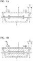
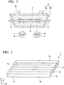
- FIG. 1A to FIG. 2 are cross-sectional views of the composite heat transfer member according to the present embodiment that is in the production process.
- a heat spreader is produced in the following manner.
- a carbon plate 1 is prepared as one of the heat transfer members constituting the composite heat transfer member.
- FIG. 3 is a perspective view showing the structure of the plate 1.
- the plate 1 is a plate-like heat transfer member obtained by laminating graphenes 2.
- the graphenes 2 are laminated in the Y direction. That is, the graphenes 2 are laminated in a direction perpendicular to the thickness direction (Z direction) of the plate 1.
- the in-plane direction of the graphenes 2 is the X-Z direction.
- the thermal conductivity in the in-plane direction of the graphenes 2 is higher than the thermal conductivity in the lamination direction of the graphenes 2.
- the plate 1 has anisotropic thermal conductivity in which the thermal conductivity in the X direction and the Z direction is higher than the thermal conductivity in the Y direction.
- the heat transfer member in which the thermal conductivity in the X direction and the Z direction is higher than the thermal conductivity in the Y direction will be called XZ heat transfer member as well.
- the thermal conductivity in the X direction and the Z direction is about 800 W/m ⁇ k
- the thermal conductivity in the Y direction is about 10 to 20 W/m.k.
- the material of the plate 1 is not limited to the laminate of the graphenes 2.
- the material graphite, Highly Oriented Pyrolytic Graphite (HOPG), or diamond can be used.
- Atop surface 1a and a bottom surface 1b of the plate 1 are rectangular.
- the direction along which long sides of the top surface 1a and the bottom surface 1b extend is the X direction, and the direction along which short sides of the top surface 1a and the bottom surface 1b extend is the Y direction.
- a fixing tool 3 is mounted on both ends in the X direction thereof.
- the plate 1 with the fixing tools is installed in the internal space of a lower portion 4b of a casting mold 4.
- an upper portion 4a of the casting mold is loaded on and fixed to the lower portion 4b.
- a cavity 6 is formed between the lower portion 4b and the upper portion 4a.
- the plate 1 is disposed in the cavity 6 of the casting mold 4.
- the molten metal 7 is supplied into the cavity 6 of the casting mold 4.
- the type of the metal 7 is not particularly limited.
- a magnesium alloy or an aluminum alloy can be used as the metal 7, a magnesium alloy or an aluminum alloy can be used as the metal 7, a magnesium alloy or an aluminum alloy can be used.
- a magnesium alloy which is constituted with magnesium containing aluminum and zinc and has a thermal conductivity of about 51 to 100 W/m ⁇ k. By heating the magnesium alloy at a temperature of about 700°C, the molten metal 7 is formed.
- the temperature of the casting mold 4 is lower than the solidification temperature (about 400°C) of the magnesium alloy.
- the molten metal 7 starts to be solidified immediately after being supplied into the cavity 6.
- a cast-molded article 8 is formed which covers the surfaces of the plate 1 except for the portions on which the fixing tool 3 is mounted.
- the patterns of the surface asperities of the plate 1 are transferred to the cast-molded article 8, and consequently, the cast-molded article 8 contacts the surfaces of the plate 1 by surface-to-surface contact.
- the magnesium alloy as a material of the cast-molded article 8 shrinks while the temperature thereof is being decreased to room temperature from the solidification temperature thereof.
- the laminate of the graphenes 2 as a material of the plate 1 substantially does not shrink or slightly expands.
- the cast-molded article 8 is in tight contact with the surfaces of the plate 1.
- the thermal resistance in the bonding interface between the cast-molded article 8 and the plate 1 is reduced, and the thermal conduction efficiency between the cast-molded article 8 and the plate 1 is improved.
- the upper portion 4a of the casting mold 4 is detached from the lower portion 4b, and the plate 1 and the cast-molded article 8 are taken out of the lower portion 4b together with the fixing tools 3. Thereafter, a portion of the plate 1 and the cast-molded article 8 is cut, and the fixing tools 3, residues, and the like are removed.
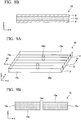
- FIG. 4A is a perspective view showing the structure of the composite heat transfer member 9.
- FIG. 4B is a cross-sectional view taken along the line I-I of the structure.
- the composite heat transfer member 9 includes the plate 1, which is the laminate of the graphenes 2, as a heat transfer member on one side and the cast-molded article 8 of a magnesium alloy, which covers the surfaces of the plate 1 except for lateral surfaces 1c in the X direction, as a heat transfer member on the other side.
- the plate 1 is an XZ heat transfer member in which the thermal conductivity in the X direction and the Z direction is higher than the thermal conductivity in the Y direction. Therefore, basically, the composite heat transfer member 9 including the plate 1 is also an XZ heat transfer member.
- the thermal conductivity in the Y direction that is relatively low can also be increased.
- the surfaces of the carbon plate 1 are covered with the metal cast-molded article 8.
- the cast-molded article 8 contacts the surfaces of the plate 1 by surface-to-surface contact, and a difference in shrinkage is caused between the cast-molded article 8 and the plate 1.
- the cast-molded article 8 is pressed on the surfaces of the plate 1 as being indicated by the arrows in the circles of broken lines in FIG. 2 .
- the cast-molded article 8 is in tight contact with the surfaces of the plate 1. Consequently, the thermal resistance in the bonding interface between the cast-molded article 8 and plate 1 is reduced, and the thermal conductivity of the composite heat transfer member 9 can be improved even though a thermally conductive member or a thermally conductive adhesive is not used.
- the composite heat transfer member 9 is used in a high-temperature environment with a temperature of about 150°C, the residual stresses are not lost even if being reduced. Therefore, the cast-molded article 8 remains pressed on the surfaces of the plate 1 as being indicated by the arrows in the circles of broken lines in FIG. 4B .
- the excellent thermal conductivity between the cast-molded article 8 and the plate 1 can be maintained.
- the lateral surfaces 1c of the plate 1 are exposed without being covered with the cast-molded article 8.
- the composite heat transfer member 9 by combining the plate 1, which is the laminate of the graphenes 2, with the cast-molded article 8 of a magnesium alloy, it is possible to obtain thermal conductivity approximately the same as the thermal conductivity of copper (391 W/m ⁇ k) and to greatly reduce the specific gravity of the composite heat transfer member 9 (2.1 g/cm 3 ) compared to the specific gravity of copper (8.9 g/cm 3 ).
- the composite heat transfer member 9 can be lightened or compactified.
- the inventor of the present application prepared a heat transfer member formed only of copper as a comparative example and calculated a thermal resistance ratio of each of the heat transfer member and the composite heat transfer member 9 according to the present embodiment.
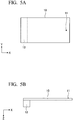
- FIG. 5A is a top view showing the positional relationship among a model used for calculating the thermal resistance ratio, a pointlike heat source as a heating portion, and a cooling portion.
- FIG. 5B is a lateral view showing the positional relationship among these.
- each of the composite heat transfer member 9 as a model 10 and the copper heat transfer member is 37 mm long in the Y direction and 3 mm long in the Z direction, that is, 3 mm thick. Furthermore, the thermal resistance ratio between a pointlike heat source 11 and a cooling portion 12 was calculated while varying the length of the model 10 in the X direction.
- the pointlike heat source 11 is 1 mm long in the X direction and 1 mm long in the Y direction.
- the pointlike heat source 11 was disposed at a position 5 mm distant from one end of the model 10 in the X direction.
- the cooling portion 12 was disposed in a region extending 10 mm from another end of the model 10 in the X direction.
- FIG. 6 is a graph showing the results obtained by calculating the thermal resistance ratio of the composite heat transfer member 9 of the present embodiment and the heat transfer member of the comparative example.
- the abscissa shows the length of the model 10 in the X direction
- the ordinate shows the thermal resistance ratio of a sample.
- the thermal resistance ratio of the heat transfer member of the comparative example remains lower than the thermal resistance ratio of the composite heat transfer member 9 of the present embodiment.
- the thermal resistance ratio of the composite heat transfer member 9 of the present embodiment becomes lower than the thermal resistance ratio of the heat transfer member of the comparative example.
- the thermal resistance ratio of the composite heat transfer member 9 is reduced and becomes about 74% of the thermal resistance ratio of the heat transfer member of the comparative example.
- the composite heat transfer member 9 of the present embodiment has a thermal resistance reducing effect.
- a plate of an XZ heat transfer member was used as the plate 1.
- a plate of a heat transfer member having anisotropic thermal conductivity different from the anisotropic thermal conductivity of the XZ heat transfer member will be used.
- FIG. 7 is a perspective view showing the structure of the plate of the present modification example.
- a plate 13 is a thin plate-like heat transfer member formed of the laminate of the graphenes 2.
- the graphenes 2 are laminated in the thickness direction, that is, in the Z direction.
- the plate 13 has anisotropic thermal conductivity in which the thermal conductivity in the X direction and the Y direction is higher than the thermal conductivity in the Z direction.
- the heat transfer member in which the thermal conductivity in the X direction and the Y direction is higher than the thermal conductivity in the Z direction will be called XY heat transfer member as well.
- FIG. 8A is a perspective view showing the structure of the composite heat transfer member.
- FIG. 8B is a cross-sectional view taken along the line III-III of the structure.
- a composite heat transfer member 14 includes the plate 13, which is the laminate of the graphenes 2, and the cast-molded article 8 of a magnesium alloy covering the surfaces of the plate 13 except for lateral surfaces 13c in the X direction.
- the plate 13 is an XY heat transfer member in which the thermal conductivity in the X direction and the Y direction is higher than the thermal conductivity in the Z direction. Therefore, basically, the composite heat transfer member 14 including the plate 13 is also an XY heat transfer member.
- the thermal conductivity in the Z direction that is relatively low can also be increased.
- a plate having a shape different from the shape of the plate 1 will be used.
- FIG. 9A is a perspective view showing the structure of the plate of the present modification example.
- FIG. 9B is a cross-sectional view taken along the line IV-IV of the structure.
- a plate 15 is a thin plate-like XZ heat transfer member formed of the laminate of the graphenes 2.
- the plate 15 of the present modification example is provided with through holes 15d that extend from a top surface 15a to a bottom surface 15b.
- the position where the through holes 15d are provided and the number of the through holes 15d are not particularly limited. In the present embodiment, at the center of the plate 15 in the X direction, two through holes 15d that are spaced in the Y direction are provided.
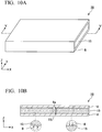
- FIG. 10A is a perspective view showing the structure of the composite heat transfer member.
- FIG. 10B is a cross-sectional view taken along the line V-V of the structure.
- a composite heat transfer member 16 includes the plate 15, which is the laminate of the graphenes 2, and the cast-molded article 8 of a magnesium alloy covering the surfaces of the plate 15 except for lateral surfaces 15c in the X direction.
- a portion 8a of the cast-molded article 8 fills up the through holes 15d of the plate 15.
- the cast-molded article 8 which covers the top surface 15a of the plate 15, is connected to the cast-molded article 8 which covers the bottom surface 15b.
- the composite heat transfer member 16 is used in a high-temperature environment, the residual tensile stress TS is not lost. Therefore, the cast-molded article 8 remains pressed on the surfaces of the plate 15 as being indicated by the arrows in the circles of broken lines. Accordingly, the excellent thermal conductivity between the cast-molded article 8 and the plate 15 can be maintained.
- a composite heat transfer member is produced by a casting method different from the method in the first embodiment.
- FIG. 11A to FIG. 12 are cross-sectional views of a composite heat transfer member according to the present embodiment that is in the production process.
- the same elements as those in the first embodiment will be marked with the same reference signs as those in the first embodiment and will not be described in the following section.
- a heat spreader will be produced in the following manner.
- a carbon plate 1, which is one of the heat transfer members constituting the composite heat transfer member, and a metal tray 17 accommodating the plate 1 are prepared.
- the plate 1 is a thin plate-like XZ heat transfer member formed of the laminate of the graphenes 2.
- the tray 17 has the following structure.
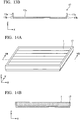
- FIG. 13A is a perspective view showing the structure of the tray 17.
- FIG. 13B is a cross-sectional view taken along the line VI-VI of the structure.
- the tray 17 is an open-top metal container with bottom.
- each of outer lateral surfaces 17a of the tray 17 is provided with a depression 17b.
- the function of the depression 17b will be described later.
- the type of metal forming the tray 17 is not particularly limited.
- a magnesium alloy or an aluminum alloy can be used as the metal forming the tray 17, as the metal forming the tray 17, a magnesium alloy or an aluminum alloy can be used.
- a magnesium alloy is used which is constituted with magnesium containing aluminum and zinc and has a thermal conductivity of about 51 to 100 W/m.k.
- the method for preparing the tray 17 is not particularly limited.
- the tray 17 can be obtained by a thixomolding method or a die casting method which will be described later.
- the plate 1 and the tray 17 having the structure described above are prepared, the plate 1 is accommodated in the tray 17.
- FIG. 14A is a perspective view showing a structure in a state where the plate 1 is accommodated in the tray 17.
- FIG. 14B is a cross-sectional view taken along the line VII-VII of the structure.
- the plate 1 is accommodated in the tray 17 such that the bottom surface 1b among the surfaces of the plate 1 contacts an inner bottom surface 17c of the tray 17 (see FIG. 13A and FIG. 13B ).
- the bottom surface 1b and the lateral surfaces 1c of the plate 1 are covered with the tray 17, and only the top surface 1a of the plate 1 is exposed.
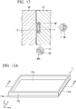
- the plate 1 and the tray 17 are disposed in the cavity of a mold of a casting device.
- FIG. 15 is a view showing the constitution of the casting device.
- the cross-sectional structure of a portion of a molding portion which will be described later, is also shown.
- a casting device 18 is a device producing a metal cast-molded article by a thixomolding method, and includes a raw material supply portion 19, a molten metal injection portion 20, and a molding portion 21.
- the raw material supply portion 19 is connected to the molten metal injection portion 20, and supplies metal chips as a raw material of a molten metal, which will be described later, to the molten metal injection portion 20.
- the type of metal chips as a raw material is not particularly limited.
- magnesium alloy chips or aluminum alloy chips can be used as the metal chips.
- magnesium alloy chips are used which are constituted with magnesium containing aluminum and zinc and have a thermal conductivity of about 51 to 100 W/m ⁇ k.
- the molten metal injection portion 20 melts the metal chips supplied from the raw material supply portion 19 and injects the molten metal into the molding portion 21 while applying pressure to the molten metal.
- the molten metal injection portion 20 includes a cylinder 22, a heater 23 covering the outer surface of the cylinder 22, and a screw (not shown in the drawing) installed in the internal space of the cylinder 22.
- the operation of the cylinder 22, the heater 23, and the screw will be described later.
- the molding portion 21 includes an immovable mold 25 mounted on a fixing board 24 and a movable mold 27 mounted on a moving board 26. By the movement of the movable mold 27, a cavity 28 between the immovable mold 25 and the movable mold 27 is closed (formed) or opened.
- the plate 1 and the tray 17 are loaded on a surface 25a of the immovable mold 25 and fixed by fixing tools not shown in the drawing, such that an outer bottom surface 17d of the tray 17 contacts the surface 25a of the immovable mold 25.
- the movable mold 27 is moved to the immovable mold 25 such that the cavity 28 is formed between the immovable mold 25 and the movable mold 27.
- the plate 1 and the tray 17 are disposed in a state where the plate 1 is accommodated in the tray 17.
- a molten metal is supplied into the cavity 28 in the following manner.
- the cylinder 22 is preheated by the heater 23.
- magnesium allow chips are used as a raw material. Therefore, by the heater 23, the cylinder 22 is preheated to a temperature of about 600°C which is close to the melting point of the magnesium alloy.
- the immovable mold 25 and the movable mold 27 are preheated to a temperature of about 300°C.
- the magnesium alloy chips are put into the cylinder 22 from the raw material supply portion 19. Then, the screw not shown in the drawing is rotated in the cylinder 22.
- the magnesium alloy chips become in a semi-molten state in which solids and a liquid coexist. Furthermore, by the rotation of the screw, shear stress is applied to the magnesium alloy in the aforementioned state. Consequently, dendritic solid phases are finely shredded and become in the form of particles.
- a thixotropic magnesium alloy with reduced viscosity and increased fluidity is formed in the cylinder 22. Furthermore, by the rotation of the screw, the thixotropic magnesium alloy is injected into the molding portion 21 as a molten metal 29 under pressure.
- the molten metal 29 is supplied into the cavity 28 between the molds 25 and 27 of the molding portion 21.
- the molds 25 and 27 are at a temperature of about 300°C which is lower than the solidification temperature (about 400°C) of the magnesium alloy. Therefore, the molten metal 29 starts to be solidified immediately after being supplied into the cavity 28.
- a heater (not shown in the drawing) of the molds 25 and 27 is turned off, such that the temperature of the metal 29 is reduced to about room temperature, and a cast-molded article 30 is formed which covers the outer lateral surfaces 17a of the tray 17 and the top surface 1a of the plate 1.
- the patterns of the asperities of the outer lateral surfaces 17a of the tray 17 and the top surface 1a of the plate 1 are transferred to the cast-molded article 30.
- the cast-molded article 30 contacts the outer lateral surfaces 17a of the tray 17 and the top surface 1a of the plate 1 by surface-to-surface contact.
- the magnesium alloy as a material of the cast-molded article 30 shrinks while the temperature thereof is being decreased to room temperature from the solidification temperature thereof.
- the laminate of the graphenes 2 as a material of the plate 1 substantially does not shrink or slightly expands.
- the cast-molded article 30 is in tight contact with the top surface 1a of the plate 1.
- the thermal resistance in the bonding interface between the cast-molded article 30 and the plate 1 is reduced, and the thermal conductivity between the cast-molded article 30 and the plate 1 is improved.
- the movable mold 27 is moved to be separated from the immovable mold 25, and the cast-molded article 30 that is covering the plate 1 and the tray 17 is taken out of the immovable mold 25.
- FIG. 16A is a perspective view showing the structure of the composite heat transfer member 31.
- FIG. 16B is a cross-sectional view taken along the line VIII-VIII of the structure.
- the composite heat transfer member 31 includes the plate 1, which is the laminate of the graphenes 2, as a heat transfer member on one side, the tray 17 of a magnesium alloy, which covers the surfaces of the plate 1 except for the top surface 1a, as a heat transfer member on the other side, and the cast-molded article 30 of a magnesium alloy which covers the top surface 1a of the plate 1.
- the plate 1 is an XZ heat transfer member in which the thermal conductivity in the X direction and the Z direction is higher than the thermal conductivity in the Y direction. Therefore, basically, the composite heat transfer member 31 including the plate 1 is also an XZ heat transfer member.
- the thermal conductivity in the Y direction that is relatively low can also be increased.
- the surfaces of the carbon plate 1 are covered with the metal tray 17 and the cast-molded article 30.
- the top surface 1a of the plate 1 is covered with the cast-molded article 30.
- the cast-molded article 30 contacts the top surface 1a of the plate 1 by surface-to-surface contact, and a difference in shrinkage is caused between the cast-molded article 30 and the plate 1 at the time of forming the cast-molded article 30. As a result, the cast-molded article 30 is pressed on the top surface 1a of the plate 1.
- the cast-molded article 30 is in tight contact with the top surface 1a of the plate 1.
- the thermal resistance in the bonding interface between the cast-molded article 30 and the plate 1 is reduced, and as a result, it is possible to improve the thermal conductivity between the cast-molded article 30 and the plate 1 without using a thermally conductive member or a thermally conductive adhesive.
- the cast-molded article 30 remains pressed on the top surface 1a of the plate 1 as being indicated by the arrows in the circles of broken lines in FIG. 16B .
- the excellent thermal conductivity between the cast-molded article 30 and the plate 1 can be maintained.
- the composite heat transfer member 31 by combining the plate 1, which is the laminate of the graphenes 2, with the tray 17 and the cast-molded article 30 of a magnesium alloy, it is possible to obtain thermal conductivity approximately the same as the thermal conductivity of copper and to greatly reduce the specific gravity of the composite heat transfer member 31 compared to the specific gravity of copper.
- the composite heat transfer member 31 can be lightened or compactified.
- the plate 1 is accommodated in the metal tray 17, it is easy to handle the plate 1 which has a brittle composition and is easily broken.
- the projection 30b of the cast-molded article 30 is fitted with the depression 17b of the outer lateral surfaces 17a of the tray 17. Therefore, it is possible to inhibit the cast-molded article 30 from being detached from the tray 17.
- the cast-molded article 30 is formed by a thixomolding method.
- the method for forming the cast-molded article 30 is not particularly limited.
- the cast-molded article may be formed by a die casting method.
- the plate 1 as an XZ heat transfer member is accommodated in the tray 17
- the plate 13 as an XY heat transfer member shown in FIG. 7 may be accommodated in the tray 17.
- a desired heat transfer pathway may be formed of a plate as an XZ heat transfer member and a plate as an XY heat transfer member, and the plates may be accommodated in the tray 17.
- a plate and a tray having shapes different from the shapes of the plate and the tray in the second embodiment will be used.
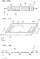
- FIG. 17A is a perspective view showing the structure of the plate of the present modification example.
- FIG. 17B is a cross-sectional view taken along the line IX-IX of the structure.
- a plate 32 is a thin plate-like XY heat transfer member formed of the laminate of the graphenes 2.
- the plate 32 of the present modification example is provided with through holes 32d that penetrate the plate from a top surface 32a to a bottom surface 32b.
- the position where the through holes 32d are provided and the number of the through holes 32d are not particularly limited. In the present embodiment, at the left end, center, and right end of the plate 32 in the X direction, two through holes 32d that are spaced in the Y direction are provided.
- FIG. 18A is a perspective view showing the structure of the tray of the present modification example.
- FIG. 18B is a cross-sectional view taken along the line X-X of the structure.
- a tray 33 is an open-top metal container with bottom.
- the lower portion of outer lateral surfaces 33a of the tray 33 is provided with a depression 33b.
- First openings 33e are provided at the center of the bottom of the tray 33, and second openings 33f larger than the first opening 33e are provided at the left end and the right end of the bottom of the tray 33. The position where the openings 33e and 33f are provided and the number of the openings will be described later.
- Each of the first openings 33e and the second openings 33f has a tapered shape having width decreasing toward an inner bottom surface 33c from an outer bottom surface 33d of the tray 33.
- the type of metal forming the tray 33 is not particularly limited.
- a magnesium alloy or an aluminum alloy can be used as a metal forming the tray 33.
- a magnesium alloy is used which is constituted with magnesium containing aluminum and zinc and has a thermal conductivity of about 51 to 100 W/m ⁇ k.
- the method for preparing the tray 33 is not particularly limited.
- the tray 33 can be prepared by a thixomolding method or a die casting method.
- the plate 32 and the tray 33 having the structure described above are prepared, the plate 32 is accommodated in the tray 33.
- FIG. 19A is a perspective view showing a structure in a state where the plate 32 is accommodated in the tray 33.
- FIG. 19B is a cross-sectional view taken along the line XI-XI of the structure.
- the plate 32 is accommodated in the tray 33 such that a bottom surface 32b among the surfaces of the plate 32 contacts an inner bottom surface 33c of the tray 33 (see FIG. 18A and FIG. 18B ).
- the bottom surface 32b and lateral surfaces 32c of the plate 32 are covered with the tray 33, and only the top surface 32a of the plate 32 is exposed.
- two through holes 32d at the center communicate with two first openings 33e at the center of the tray 33 along the thickness direction (Z direction) of the plate 32.
- Two through holes 32d at the right end portion communicate with two second openings 33f, which are larger than the through holes 32d and positioned at the left end of the tray 33, along the Z direction.
- Two through holes 32d at the right end communicate with two second openings 33f, which are larger than the through holes 32d and positioned at the right end of the tray 33, along the Z direction.
- FIG. 20A is a perspective view showing the structure of the composite heat transfer member.
- FIG. 20B is a cross-sectional view taken along the line XII-XII of the structure.
- a composite heat transfer member 34 includes the plate 32, which is the laminate of the graphenes 2, as a heat transfer member on one side, the tray 33 of a magnesium alloy, which covers the surfaces of the plate 32 except for the top surface 32a, as a heat transfer member on the other side, and the cast-molded article 30 of a magnesium alloy which covers the top surface 32a of the plate 32.
- a portion 30a of the cast-molded article 30 fills up the through holes 32d of the plate 32 and the openings 33e and 33f of the tray 33.
- the cast-molded article 30 covering the top surface 32a of the plate 32 is connected to the cast-molded article 30 covering the bottom surface 32b.
- the composite heat transfer member 34 In a case where the composite heat transfer member 34 is used in a high-temperature environment, the residual tensile stress TS is not lost. Therefore, the cast-molded article 30 remains pressed on the top surface 32a of the plate 32 as being indicated by the arrows in the circles of broken lines.
- the second openings 33f of the tray 33 are larger than the through holes 32d of the plate 32 that communicate with the second openings 33f.
- the cast-molded article 30 can also remain pressed on the bottom surface 32b of the plate 32 as being indicated by the arrows in the circles of broken lines.
- the projection 30b of the cast-molded article 30 is fitted with the depression 33b of outer lateral surfaces 33a of the tray 33. Furthermore, the portion 30a of the cast-molded article 30 is fitted with the tapered first openings 33e and the tapered second openings 33f at the bottom of the tray 33.
- a heat spreader As a composite heat transfer member, a heat spreader was produced. However, in the present embodiment, as a composite heat transfer member, a heat spreader that also functions as a heat sink will be produced.
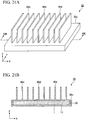
- FIG. 21A is a perspective view showing the structure of the composite heat transfer member.
- FIG. 21B is a cross-sectional view taken along the line XIII-XIII of the structure.
- the same elements as those in the second embodiment will be marked with the same reference signs as those in the second embodiment and will not be described in the following section.
- a composite heat transfer member 35 according to the present embodiment has the same structure as the structure of the composite heat transfer member 31 according to the second embodiment.
- the composite heat transfer member 35 also includes the plate 1, which is the laminate of the graphenes 2, as a heat transfer member on one side, the tray 17 of a magnesium alloy, which covers the surfaces of the plate 1 except for the top surface 1a, as a heat transfer member on the other side, and the cast-molded article 30 of a magnesium alloy which covers the top surface 1a of the plate 1.
- a plurality of fins 30d are provided on the outer top surface 30c of the cast-molded article 30.
- the composite heat transfer member 35 having the structure described above can be obtained by performing the same steps as the steps in the second embodiment shown in FIG. 11A to FIG. 12 .
- the fins 30d are provided on the cast-molded article 30.
- the composite heat transfer member 35 the heat generated from electronic components or electronic instruments can be moved and dissipated from the fins 30d.
- the cast-molded article 30 and the fins 30d are integrated. Accordingly, in this case, thermal resistance can be further reduced than in a case where a cast-molded article and fins are separately provided, because a thermally conductive member or a thermally conductive adhesive for bonding the cast-molded article to the fins is not used.
- the composite heat transfer member 35 according to the present embodiment has the same structure as the structure of the composite heat transfer member 31 according to the second embodiment.
- the composite heat transfer member 35 is not limited to the structure.
- the composite heat transfer member according to the present embodiment may have a structure that is basically the same as the structure of the composite heat transfer member 9 according to the first embodiment.
- a plurality of fins may be provided on the outer top surface of the cast-molded article 8.
- the plate 1 a plate which is an XZ heat transfer member was used.
- a plate which is constituted with heat transfer members having two kinds of anisotropic thermal conductivity.
- FIG. 22 is a perspective view showing the structure of the plate of the present embodiment.
- a plate 41 includes a heat transfer member 101 and a heat transfer member 43.
- the heat transfer member 101 has the same structure as the structure of the plate 1. That is, in the heat transfer member 101, the graphenes 2 are laminated in the Y direction, and the in-plane direction of the graphenes 2 is the X-Z direction. Accordingly, the heat transfer member 101 is an XZ heat transfer member.
- the heat transfer member 43 is a thin plate-like heat transfer member formed of the laminate of the graphenes 2.
- the graphenes 2 are laminated in the thickness direction of the heat transfer member 43, that is, in the Z direction, and the in-plane direction of the graphenes 2 is the X-Y direction. Accordingly, the heat transfer member 43 is an XY heat transfer member.
- the dimension of the heat transfer member 43 in the Y direction is identical to the dimension of the heat transfer member 101 in the Y direction, one lateral surface of the heat transfer member 101 in the X direction contacts a lateral surface of the heat transfer member 43 in the X direction, and one end of the heat transfer member 101 in the X direction is connected to the heat transfer member 43.
- a top surface 41a and a bottom surface 41b of the plate 41 are rectangular.
- the direction along which long sides of the top surface 41a and the bottom surface 41b extend is the X direction, and the direction along which short sides of the top surface 41a and the bottom surface 41b extend is the Y direction.
- FIG. 23A is a perspective view showing the structure of the composite heat transfer member.
- FIG. 23B is a cross-sectional view taken along the line XIV-XIV of the structure.
- a composite heat transfer member 49 includes the plate 41, which the laminate of the graphenes 2, and the cast-molded article 8 of a magnesium alloy which covers the surfaces of the plate 41 except for lateral surfaces 41c in the X direction.
- FIG. 24 is a view showing an example of a heat transfer pathway in the plate 41 of the fourth embodiment.
- FIG. 24 shows the heat transfer pathway in the X-Y plane.
- a heat source 100 is assumed to be at the center of the bottom surface 41b of the plate 41.
- the heat generated from the heat source 100 is transferred along the Z direction through graphene positioned around the center of the Y direction among the graphenes 2 constituting the heat transfer member 101, and transferred along the X direction as well (arrow A). Thereafter, a portion of the heat is transferred to the heat transfer member 43 at one end of the heat transfer member 101 in the X direction. The heat is then transferred along the X direction through the heat transfer member 43 and transferred along the Y direction as well (arrow B). A portion of the heat transferred through the heat transfer member 43 is transferred to the heat transfer member 101. The heat is then transferred along the Z direction through the heat transfer member 101 and transferred along the X direction as well (arrow C). Because the plate 41 is in tight contact with the cast-molded article 8, the heat is released out of the cast-molded article 8.
- the fourth embodiment it is possible to obtain the same effect as that in the first embodiment and to obtain excellent thermal conductivity in the X direction and the Y direction.
- the composite heat transfer member 49 even after the composite heat transfer member 49 is produced, residual tensile stress exists in the cast-molded article 8 while residual compressive stress exists in the plate 41.
- the composite heat transfer member 49 is used in a high-temperature environment with a temperature of about 150°C, the residual stresses are not lost even if being reduced. Therefore, the cast-molded article 8 remains pressed on the surfaces of the plate 41 as being indicated by the arrows in the circles of broken lines in FIG. 23B . Accordingly, the excellent thermal conductivity between the cast-molded article 8 and the plate 41 can be maintained.
- a plate having a shape different from the shape of the plate 41 will be used.
- FIG. 25A is a perspective view showing the structure of the plate of the present modification example.
- FIG. 25B is a cross-sectional view taken along the line XV-XV of the structure.
- a plate 44 includes a heat transfer member 115 instead of the heat transfer member 101.
- the heat transfer member 115 has the same structure as the structure of the plate 15. That is, the heat transfer member 115 is a thin plate-like XZ heat transfer member which is formed of the laminate of the graphenes 2 and is provided with through holes 44d that extend from a top surface 44a to a bottom surface 44b.
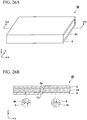
- FIG. 26A is a perspective view showing the structure of the composite heat transfer member.
- FIG. 26B is a cross-sectional view taken along the line XVI-XVI of the structure.
- a composite heat transfer member 46 includes the plate 44, which is the laminate of the graphenes 2, and the cast-molded article 8 of a magnesium alloy which covers the surfaces of the plate 44 except for lateral surfaces 44c in the X direction.
- a portion 8a of the cast-molded article 8 fills up the through holes 44d of the plate 44.
- the cast-molded article 8 covering the top surface 44a of the plate 44 is connected to the cast-molded article 8 covering the bottom surface 44b.
- the composite heat transfer member 46 is used in a high-temperature environment, the residual tensile stress TS is not lost. Therefore, the cast-molded article 8 remains pressed on the surfaces of the plate 44 as being indicated by the arrows in the circles of broken lines. Therefore, the excellent thermal conductivity between the cast-molded article 8 and the plate 44 can be maintained.
- a composite heat transfer member will be produced by a casting method different from the method in the fourth embodiment. That is, in the present embodiment, the plate 41 and the tray 17 shown in FIG. 13A and FIG. 13B are prepared, and a composite heat transfer member is produced by the same method as that in the second embodiment.
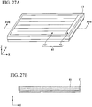
- FIG. 27A is a perspective view showing a structure in a state where the plate 41 is accommodated in the tray 17.
- FIG. 27B is a cross-sectional view taken along the line XVII-XVII of the structure.
- the plate 41 is accommodated in the tray 17 such that the bottom surface 41b among the surfaces of the plate 41 contacts the inner bottom surface 17c of the tray 17 (see FIG. 13A and FIG. 13B ).
- the bottom surface 41b and the lateral surfaces 41c of the plate 41 are covered with the tray 17, and only the top surface 41a of the plate 41 is exposed.
- the plate 41 and the tray 17 that are in a state where the plate 41 is accommodated in the tray 17 are disposed in the cavity 28 between the movable mold 27 and the immovable mold 25 of the casting device 18, and a molten metal is supplied into the cavity 28, thereby forming the cast-molded article 30.
- the movable mold 27 is moved to be separated from the immovable mold 25, and the cast-molded article 30 that is covering the plate 41 and the tray 17 is taken out of the immovable mold 25.
- FIG. 28A is a perspective view showing the structure of the composite heat transfer member 51.
- FIG. 28B is a cross-sectional view taken along the line XVIII-XVIII of the structure.
- the composite heat transfer member 51 includes the plate 41, which is the laminate of the graphenes 2, as a heat transfer member on one side, the tray 17 of a magnesium alloy, which covers the surfaces of the plate 41 except for the top surface 41a, as a heat transfer member on the other side, and the cast-molded article 30 of a magnesium alloy which covers the top surface 41a of the plate 41.
- the fifth embodiment it is possible to obtain the effects of the fourth embodiment and the second embodiment.
- the composite heat transfer member 51 due to the difference in shrinkage that is caused between the cast-molded article 30 and the plate 41 at the time of forming the cast-molded article 30, even after the composite heat transfer member 51 is produced, residual tensile stress exists in the cast-molded article 30 while residual compressive stress exists in the plate 41.
- the composite heat transfer member 51 is used in a high-temperature environment, the residual stresses are not lost. Therefore, the cast-molded article 30 remains pressed on the top surface 41a of the plate 41 as being indicated by the arrows in the circles of broken lines in FIG. 28B . Accordingly, the excellent thermal conductivity between the cast-molded article 30 and the plate 41 can be maintained.
- a plate and a tray having shapes different from the shapes of the plate and the tray in the fifth embodiment will be used.
- FIG. 29A is a perspective view showing the structure of the plate of the present modification example.
- FIG. 29B is a cross-sectional view taken along the line XIX-XIX of the structure.
- a plate 52 includes a heat transfer member 132 instead of the heat transfer member 101.
- the heat transfer member 132 has the same structure as the plate 32. That is, the heat transfer member 132 is a thin plate-like XZ heat transfer member which is formed of the laminate of the graphenes 2 and is provided with through holes 52d that extend from a top surface 52a to a bottom surface 52b.
- the tray 33 shown in FIG. 18A and FIG. 18B is used as a tray.
- the plate 52 and the tray 33 are prepared, and then the plate 52 is accommodated in the tray 33.
- FIG. 30A is a perspective view showing a structure in a state where the plate 52 is accommodated in the tray 33.
- FIG. 30B is a cross-sectional view taken along the line XX-XX of the structure.
- the plate 52 is accommodated in the tray 33 such that the bottom surface 52b among the surfaces of the plate 52 contacts the inner bottom surface 33c of the tray 33 (see FIG. 18A and FIG. 18B ).
- the bottom surface 52b and the lateral surfaces 52c of the plate 52 are covered with the tray 33, and only the top surface 52a of the plate 52 is exposed.
- two through holes 52d at the center communicate with two first openings 33e at the center of the tray 33 along the thickness direction (Z direction) of the plate 52.
- Two through holes 52d at the left end communicate with the second opening 33f, which is larger than the through holes 52d and positioned at the left end of the tray 33, along the Z direction. Furthermore, two through holes 52d at the right end communicate with the second opening 33f, which is larger than the through holes 52d and positioned at the right end of the tray 33, along the Z direction.
- FIG. 31A is a perspective view showing the structure of the composite heat transfer member.
- FIG. 31B is a cross-sectional view taken along the line XXI-XXI of the structure.
- a composite heat transfer member 54 includes the plate 52, which is the laminate of the graphenes 2, as a heat transfer member on one side, the tray 33 of a magnesium alloy, which covers the surfaces of the plate 52 except for the top surface 52a, as a heat transfer member on the other side, and the cast-molded article 30 of a magnesium alloy which covers the top surface 52a of the plate 52.
- a portion 30a of the cast-molded article 30 fills up the through holes 52d of the plate 52 and the openings 33e and 33f of the tray 33.
- the cast-molded article 30 covering the top surface 52a of the plate 52 is connected to the cast-molded article 30 covering the bottom surface 52b.
- the composite heat transfer member In a case where the composite heat transfer member is used in a high-temperature environment, the residual tensile stress TS is not lost. Therefore, the cast-molded article 30 remains pressed on the top surface 52a of the plate 52 as being indicated by the arrows in the circles of broken lines.
- the second openings 33f of the tray 33 are larger than the through holes 52d of the plate 52 that communicate with the second openings 33f.
- the cast-molded article 30 can also remain pressed on the bottom surface 52b of the plate 52 as being indicated by the arrows in the circles of broken lines.
- the projection 30b of the cast-molded article 30 is fitted with the depression 33b of outer lateral surfaces 33a of the tray 33. Furthermore, the portion 30a of the cast-molded article 30 is fitted with the tapered first openings 33e and the tapered second openings 33f at the bottom of the tray 33.
- a heat spreader As a composite heat transfer member, a heat spreader was produced. However, in the present embodiment, as in the third embodiment, as a composite heat transfer member, a heat spreader that also functions as a heat sink will be produced.
- FIG. 32A is a perspective view showing the structure of the composite heat transfer member.
- FIG. 32B is a cross-sectional view taken along the line XXII-XXII of the structure.
- the same elements as those in the fifth embodiment will be marked with the same reference signs as those in the fifth embodiment and will not be described in the following section.
- a composite heat transfer member 55 according to the present embodiment has the same structure as the structure of the composite heat transfer member 54 according to the modification example of the fifth embodiment.
- the composite heat transfer member 55 also includes the plate 52, which is the laminate of the graphenes 2, as a heat transfer member on one side, the tray 33 of a magnesium alloy, which covers the surfaces of the plate 52 except for the top surface 52a, as a heat transfer member on the other side, and the cast-molded article 30 of a magnesium alloy which covers the top surface 52a of the plate 52.
- a plurality of fins 30d are provided on the outer top surface 30c of the cast-molded article 30.
- the composite heat transfer member 55 having the structure described above can be obtained by performing the same steps as the steps in the second embodiment shown in FIG. 11A to FIG. 12 .
- the fins 30d are provided on the cast-molded article 30.
- the composite heat transfer member 55 the heat generated from electronic components or electronic instruments can be moved and dissipated from the fins 30d.
- the cast-molded article 30 and the fins 30d are integrated. Accordingly, in this case, thermal resistance can be further reduced than in a case where a cast-molded article and fins are separately provided, because a thermally conductive member or a thermally conductive adhesive for bonding the cast-molded article to the fins is not used.
- the composite heat transfer member 55 according to the present embodiment has a structure that is basically the same as the structure of the composite heat transfer member 54 according to the modification example of the fifth embodiment.
- the composite heat transfer member 55 is not limited to the structure.
- the composite heat transfer member according to the present embodiment may have a structure that is basically the same as the structure of the composite heat transfer member 49 according to the fourth embodiment.
- a plurality of fins may be provided on the outer top surface of the cast-molded article 8.
- the composite heat transfer member according to the present embodiment may have a structure that is basically the same as the structure of the composite heat transfer member 51 according to the fifth embodiment.
- a tray having a shape different from the shape of the tray in the fifth embodiment will be used.
- FIG. 33 is a perspective view showing the structure of the tray of the seventh embodiment.
- a tray 117 used in the seventh embodiment is a metal container just as the tray 17. As in the tray 17, a depression 117b is provided on the lower side of outer lateral surfaces 117a of the tray 117. Furthermore, on the top surface of the tray 117, five grooves 117s for an XZ heat transfer member and a groove 117t for an XY heat transfer member are formed. One end of each of the grooves 117s is connected to the groove 117t.
- the tray 117 can be prepared by the same method as that used for preparing the tray 17 by using the same material as the material of the tray 17.
- XZ heat transfer members 72 to be accommodated in the grooves 117s and an XY heat transfer member 73 to be accommodated in the groove 117t are prepared.
- the XZ heat transfer members 72 and the XY heat transfer member 73 can be prepared, for example, by the same method as that used for preparing the plate 1 or 13.
- FIG. 34 is a perspective view showing a structure in a state where the XZ heat transfer members 72 and the XY heat transfer member 73 are accommodated in the tray 117.
- the XZ heat transfer members 72 are accommodated in the grooves 117s such that the bottom surface among the surfaces of each of the XZ heat transfer members 72 contacts the inner bottom surface of the tray 117.
- the XY heat transfer member 73 is accommodated in the groove 117t such that the bottom surface among the surfaces of the XY heat transfer member 73 contacts the inner bottom surface of the tray 117.
- One lateral surface of each of the XZ heat transfer members 72 in the X direction contacts a lateral surface of the XY heat transfer member 73 in the X direction, and one end of each of the XZ heat transfer members 72 in the X direction is connected to the XY heat transfer member 73.
- a plate 71 is constituted with the XZ heat transfer members 72 and the XY heat transfer member 73.
- the bottom surface and the lateral surfaces of the plate 71 are covered with the tray 117, and only a top surface 71a of the plate 71 is exposed.
- FIG. 35A is a perspective view showing the structure of the composite heat transfer member.
- FIG. 35B is a cross-sectional view taken along the line XXIII-XXIII of the structure.
- a composite heat transfer member 74 includes the plate 71, which is the laminate of the graphenes 2, as a heat transfer member on one side, the tray 117 of a magnesium alloy, which covers the surfaces of the plate 71 except for the top surface 71a, as a heat transfer member on the other side, and the cast-molded article 30 of a magnesium alloy which covers the top surface 71a of the plate 71.
- the present embodiment it is possible to obtain the same effect as the effect of the fifth embodiment.
- the composite heat transfer member 74 due to the difference in shrinkage that is caused between the cast-molded article 30 and the plate 71 at the time of forming the cast-molded article 30, even after the composite heat transfer member 74 is produced, residual tensile stress exists in the cast-molded article 30 while residual compressive stress exists in the plate 71.
- the composite heat transfer member 74 is used in a high-temperature environment, the residual stresses are not lost. Therefore, the cast-molded article 30 remains pressed on the top surface 71a of the plate 71 as being indicated by the arrows in the circles of broken lines in FIG. 35B . Accordingly, the excellent thermal conductivity between the cast-molded article 30 and the plate 71 can be maintained.
- the magnesium alloy is lighter than graphene, the overall weight can be reduced. Moreover, the use of the magnesium alloy is effective for reducing the material cost.
- the XZ heat transfer members 72 and the XY heat transfer member 73 are accommodated in the tray 117.
- a plurality of heat transfer members of one kind may be accommodated in one tray.
- XZ heat transfer members may be accommodated in the tray at sites corresponding to the heat sources.
- other XZ heat transfer members may be accommodated in the tray such that heat can be transferred to the vicinity of the outer lateral surfaces of the tray.
- a tray having a shape different from the shape of the tray of the seventh embodiment will be used.
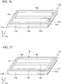
- FIG. 36 is a perspective view showing the structure of the tray of the present modification example.
- a tray 118 used in the present modification example is a metal container just as the tray 17. As in the tray 17, a depression 117b is provided on the lower side of outer lateral surfaces 117a of the tray 118. Furthermore, on the top surface of the tray 118, three grooves 118s for an XZ heat transfer member and two grooves 118t for an XY heat transfer member are formed. Both ends of each of the grooves 118s are connected to both the grooves 118t.
- the tray 118 can be prepared by the same method as that used for preparing the tray 17 by using the same material as the material of the tray 17.
- An XZ heat transfer member 76 to be accommodated in the grooves 118s and an XY heat transfer member 77 to be accommodated in the grooves 118t are prepared.
- the XZ heat transfer member 76 and the XY heat transfer member 77 can be prepared, for example, by the same method as that used for preparing the plate 1 or 13.
- FIG. 37 is a perspective view showing a structure in a state where the XZ heat transfer member 76 and the XY heat transfer member 77 are accommodated in the tray 118.
- the XZ heat transfer member 76 is accommodated in the grooves 118s such that the bottom surface among the surfaces of the XZ heat transfer member 76 contacts the inner bottom surface of the tray 118.
- the XY heat transfer member 77 is accommodated in the grooves 118t such that the bottom surface among the surfaces of the XY heat transfer member 77 contacts the inner bottom surface of the tray 118. Furthermore, lateral surfaces of the XY heat transfer member 77 in the X direction contact both the lateral surfaces of each of the XZ heat transfer members 76 in the X direction, and both ends of each of the XZ heat transfer members 76 in the X direction are connected to the XY heat transfer member 77.
- a plate 75 is constituted with the XZ heat transfer members 76 and the XY heat transfer members 77.
- the bottom surface and the lateral surfaces of the plate 75 are covered with the tray 118, and only a top surface 75a of the plate 75 is exposed.
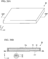
- FIG. 38A is a perspective view showing the structure of the composite heat transfer member.
- FIG. 38B is a cross-sectional view taken along the line XXIV-XXIV of the structure.
- a composite heat transfer member 79 includes the plate 75, which is the laminate of the graphenes 2, as a heat transfer member on one side, the tray 118 of a magnesium alloy, which covers the surfaces of the plate 75 except for the top surface 75a, as a heat transfer member on the other side, and the cast-molded article 30 of a magnesium alloy which covers the top surface 75a of the plate 75.
- a heat source is positioned in the vicinity of a site where the XZ heat transfer member 72 and the XY heat transfer member 73 positioned at the center in the Y direction are connected to each other.
- a heat source is positioned at the center of the XZ heat transfer member 76, which is positioned at the center in the Y direction, in the X direction. In a case where the heat source is positioned in the vicinity of the XZ heat transfer member 72 or 76, heat can be transferred with high efficiency.
- fins are provided on five XZ heat transfer members 72 in the composite heat transfer member 74 and on three XZ heat transfer members 76 in the composite heat transfer member 79 such that the composite heat transfer members also function as a heat sink.
- a heat spreader that also functions as a heat sink will be produced.
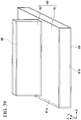
- FIG. 39 is a perspective view showing a composite heat transfer member according to an eighth embodiment.
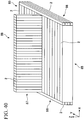
- FIG. 40 is a perspective view showing the constitution of a plate included in the composite heat transfer member according to the eighth embodiment.
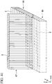
- FIG. 41 is a perspective view showing the constitution of a portion of the plate included in the composite heat transfer member according to the eighth embodiment.
- a composite heat transfer member 80 has a plate-like base portion 81 and a fin 82 erecting on the base portion 81.
- the base portion 81 has a top surface 81a and a bottom surface 81b that are parallel to the X-Y plane, and the fin 82 extends along the Z direction from the top surface 81a.
- a heat source contacts the bottom surface 81b.
- the composite heat transfer member 80 includes a plate 88, which is the laminate of the graphenes 2, as a heat transfer member on one side, and a cast-molded article 89 of a magnesium alloy, which covers the surfaces of the plate 88, as a heat transfer member on the other side.
- the plate 88 and the cast-molded article 89 are constituted such that these are in tight contact with each other by the same method as the method in the first embodiment, the second embodiment, or the like.
- the plate 88 includes an XZ heat transfer member 85, XY heat transfer members 86, and an YZ heat transfer member 87.
- the XZ heat transfer member 85 is constituted with the graphenes 2 laminated in the Y direction.
- Each of the XY heat transfer members 86 is constituted with the graphenes 2 laminated in the Z direction.
- the YZ heat transfer member 87 is constituted with the graphenes 2 laminated in the X direction.
- a lateral surface of each of the XY heat transfer members 86 contacts each of both the lateral surfaces of the XZ heat transfer member 85 in the X direction, and the XY heat transfer members 86 are connected to the XZ heat transfer member 85.
- the dimension (height) of the XZ heat transfer member 85 in the Z direction is approximately the same as the dimension (height) of each of the XY heat transfer members 86 in the Z direction, and the XZ heat transfer member 85 and the XY heat transfer members 86 are included in the base portion 81.
- the dimension of the XZ heat transfer member 85 in the X direction is approximately the same as the dimension of the YZ heat transfer member 87 in the X direction.
- the portion of the YZ heat transfer member 87 that contacts the XZ heat transfer member 85 is included in the base portion 81, and a portion that protrudes in the Z direction from the aforementioned portion is included in the fin 82.
- FIG. 42 is a view showing an example of the heat transfer pathway in the plate 88 of the eighth embodiment.
- a heat source 200 is assumed to be at the center of the bottom surface side of the XZ heat transfer member 85.
- the heat generated from the heat source 200 is transferred along the Z direction through graphene, which is positioned in the vicinity of the center in the Y direction among the graphenes 2 constituting the XZ heat transfer member 85, and transferred along the X direction as well (arrow D). Thereafter, the heat is transferred to the XY heat transfer members 86 at the end of the XZ heat transfer member 85 in the X direction. The heat is then transferred along the X direction through the XY heat transfer members 86 and transferred along the Y direction as well (arrow E). A portion of the heat transferred through the XY heat transfer members 86 is transferred to a portion of the XZ heat transfer member 85.
- the heat is then transferred along the Z direction through the XZ heat transfer member 85 and transferred along the X direction as well (arrow F). Furthermore, the heat transferred through graphene contacting the YZ heat transfer member 87 among the graphenes 2 constituting the XZ heat transfer member 85 is transferred to the YZ heat transfer member 87. The heat is then transferred along the Y direction through the YZ heat transfer member 87 and transferred along the Z direction as well (arrow G). Because the plate 88 and the cast-molded article 89 are in tight contact with each other, the heat is released out of the cast-molded article 89.
- the present embodiment relates to a composite heat transfer member which is a heat spreader that functions as a heat sink as well.
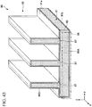
- FIG. 43 is a partial cross-sectional view showing a composite heat transfer member according to a ninth embodiment.
- a composite heat transfer member 90 has a plate-like base portion 91 and fins 92 erecting on the base portion 91.
- the base portion 91 has a top surface 91a and a bottom surface 91b that are parallel to the X-Y plane, and the fins 92 extend in the Z direction from the top surface 91a.
- a heat source contacts the bottom surface 91b.
- the base portion 91 has an XZ heat transfer member 95, which is constituted with graphenes laminated in the Y direction, and an XY heat transfer member 96 which is constituted with graphenes laminated in the Z direction.
- Each of the fins 92 has an YZ heat transfer member 97 which is constituted with graphenes laminated in the X direction.
- the YZ heat transfer member 97 contacts the XZ heat transfer member 95 and erects on the XZ heat transfer member 95 along the Z direction.
- the composite heat transfer member 90 has a cast-molded article 99B of a magnesium alloy, which covers the surfaces of each of the YZ heat transfer members 97, and a cast-molded article 99A of a magnesium alloy which covers the surfaces of the XZ heat transfer member 95 and the XY heat transfer member 96.
- the XZ heat transfer member 95, the XY heat transfer member 96, the YZ heat transfer members 97, and the cast-molded articles 99A and 99B are constituted such that these are in tight contact with each other by the same method as the method in the first embodiment, the second embodiment, or the like.
- the heat from the heat source mounted on the bottom surface 91b is released out of the cast-molded articles 99A and 99B through the XZ heat transfer member 95, the XY heat transfer member 96, and the YZ heat transfer members 97.
- the present modification example is different from the ninth embodiment in terms of the constitution of the cast-molded article 99B.
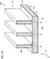
- FIG. 44 is a partial cross-sectional view showing a composite heat transfer member according to a first modification example of the ninth embodiment.
- the cast-molded article 99B also covers the surface of each of the YZ heat transfer members 97 that contacts the XZ heat transfer member 95, and the YZ heat transfer members 97 erect on the XZ heat transfer member 95 along the Z direction in a state where a portion of the cast-molded article 99B is interposed between each of the YZ heat transfer members 97 and the XZ heat transfer member 95.
- Other constitutions are the same as the constitutions of the ninth embodiment.
- the heat from the heat source mounted on the bottom surface 91b is released out of the cast-molded articles 99A and 99B through the XZ heat transfer member 95, the XY heat transfer member 96, and the YZ heat transfer members 97.
- the present modification example is different from the ninth embodiment in terms of the constitutions of the YZ heat transfer members 97 and the cast-molded article 99B.
- FIG. 45 is a partial cross-sectional view showing a composite heat transfer member according to a second modification example of the ninth embodiment.
- the dimension of each of the YZ heat transfer members 97 in the Z direction is smaller than the dimension in the ninth embodiment.
- Other constitutions are the same as the constitutions in the ninth embodiment.
- the heat from the heat source mounted on the bottom surface 91b is released out of the cast-molded articles 99A and 99B through the XZ heat transfer member 95, the XY heat transfer member 96, and the YZ heat transfer members 97.
- the dimension of each of the YZ heat transfer members 97 in the Z direction may be smaller than the dimension in the ninth embodiment.
- the present modification example is different from the ninth embodiment in terms of the constitution of the cast-molded article 99A.
- FIG. 46 is a partial cross-sectional view showing a composite heat transfer member according to a third modification example of the ninth embodiment.
- the cast-molded article 99A covers the surface of the XZ heat transfer member 95 that contacts the YZ heat transfer members 97, and the YZ heat transfer members 97 erect on the XZ heat transfer member 95 along the Z direction in a state where a portion of the cast-molded article 99A is interposed between each of the YZ heat transfer members 97 and the XZ heat transfer member 95.
- Other constitutions are the same as the constitutions in the ninth embodiment.
- the heat from the heat source mounted on the bottom surface 91b is released out of the cast-molded articles 99A and 99B through the XZ heat transfer member 95, the XY heat transfer member 96, and the YZ heat transfer members 97.
- the present embodiment relates to a composite heat transfer member suited for a specific heat source.
- FIG. 47A is a perspective view showing the structure of a composite heat transfer member according to a tenth embodiment.
- FIG. 47B is a top view of the structure.
- a composite heat transfer member 109 according to the tenth embodiment has a carbon plate 107 and a cast-molded article 108 of a magnesium alloy covering the surfaces of the plate 107.
- the plate 107 has an XZ heat transfer member 105 constituted with graphenes laminated in the Y direction perpendicular to the thickness direction (Z direction) of the plate 107.
- the composite heat transfer member 109 is used by being mounted on a heat source 102 whose dimension in the Y direction is W2. Furthermore, the dimension of the XZ heat transfer member 105 in the Y direction is W1. In the present embodiment, the dimension W1 is identical to the dimension W2.
- the composite heat transfer member 109 is mounted such that the heat source 102 overlaps the XZ heat transfer member 105 along the Y direction when seen in a plan view. Accordingly, the heat generated from the heat source 102 is transferred along the X direction and the Y direction by the XZ heat transfer member 105 with high efficiency and released to the outside.
- the heat transfer performance in the Y direction is lower than the heat transfer performance in the X direction and the Z direction. Therefore, even though the XZ heat transfer member 105 is provided to cover a wider range in the Y direction, the heat transfer performance remains substantially the same.
- a magnesium alloy is less expensive than graphene. Therefore, in a case where substantially the same heat transfer performance is obtained, a composite heat transfer member in which a small amount of graphene is used is preferable.
- the width W1 is preferably 100% to 110% of the width W2, and more preferably 100% to 105% of the width W2.
- the composite heat transfer members according to the first embodiment to the tenth embodiment described above can be applied to various components involved in heat transfer.
- the first embodiment, the second embodiment, the fourth embodiment, the fifth embodiment, the seventh embodiment, and the tenth embodiment which are heat spreaders or the composite heat transfer members 9, 16, 31, 34, 49, 46, 51, 54, 74, 79, and 109 according to modification examples of the above embodiments can be applied to water cooling jacket and cooling water piping made of copper for heating components such as Central Processing Unit (CPU) of a server or applied to a base substrate for a power module.
- CPU Central Processing Unit
- the third embodiment, the sixth embodiment, the eighth embodiment, and the ninth embodiment which are heat spreaders that also function as heat sinks or the composite heat transfer members 35, 55, 80, 90, 90A, 90B, and 90C according to modification examples of the above embodiments can be applied to a heat sink of an LED headlamps for automobiles made of aluminum or applied to a heat sink for a mobile base station.
Landscapes
- Engineering & Computer Science (AREA)
- Mechanical Engineering (AREA)
- Physics & Mathematics (AREA)
- Thermal Sciences (AREA)
- General Engineering & Computer Science (AREA)
- Microelectronics & Electronic Packaging (AREA)
- Cooling Or The Like Of Semiconductors Or Solid State Devices (AREA)
- Chemical & Material Sciences (AREA)
- Ceramic Engineering (AREA)
- Moulds For Moulding Plastics Or The Like (AREA)
Abstract
Description
- The present invention relates to a composite heat transfer member and a method for producing a composite heat transfer member.
- As a material of heat spreaders that transfer heat generated from electronic components or electronic instruments, a copper plate or a graphene laminate is used.
- Among these, the graphene laminate has higher thermal conductivity and lower specific gravity compared to the copper plate. Therefore, the graphene laminate is useful as a material of heat spreaders because this material can be compactified and lightened.
- On the other hand, the graphene laminate generally has a brittle composition. Therefore, the graphene laminate is likely to be broken due to the stress caused in a case where the laminate is brought into contact with heat sources such as electronic components or electronic instruments or mounted on a mounting portion.
- Accordingly, a composite heat transfer member is used which is obtained by covering the graphene laminate with a metal such as copper or aluminum so as to improve the overall strength.
-
- [Patent Document 1] Japanese Unexamined Patent Application, First Publication No.
2011-23670 - [Patent Document 2] Japanese Unexamined Patent Application, First Publication No.
2012-238733 - However, in the aforementioned composite heat transfer member, high thermal resistance occurs in the bonding interface between the graphene laminate and the metal, and accordingly, the overall thermal conductivity of the composite heat transfer member is reduced.
- According to an aspect, an object of the present invention is to provide a composite heat transfer member which can improve thermal conductivity and a method for producing the composite heat transfer member.
- According to an aspect of a technique that will be disclosed below, there is provided a composite heat transfer member having a carbon plate and a metal cast-molded article covering a surface of the plate.
- According to another aspect of the technique that will be disclosed below, there is provided a method for producing a composite heat transfer member having a step of disposing a carbon plate in a cavity of a casting mold and a step of covering a surface of the plate with a cast-molded article by supplying a molten metal into the cavity so as to form the cast-molded article of the metal.
- According to the technique that will be disclosed below, the surfaces of the carbon plate are covered with the metal cast-molded article. Therefore, the cast-molded article contacts the surfaces of the plate by surface-to-surface contact. Furthermore, due to the difference in shrinkage between the cast-molded article and the plate at the time of forming the cast-molded article, the cast-molded article is pressed on the surfaces of the plate.
- As a result, the cast-molded article is in tight contact with the surfaces of the plate. Therefore, the thermal resistance in the bonding interface between the cast-molded article and the plate is reduced, and the thermal conductivity of the composite heat transfer member can be improved.
-
-
FIG. 1A is a cross-sectional view (1) of a composite heat transfer member according to a first embodiment that is in the production process. -
FIG. 1B is a cross-sectional view (2) of the composite heat transfer member according to the first embodiment that is in the production process. -
FIG. 2 is a cross-sectional view (3) of the composite heat transfer member according to the first embodiment that is in the production process. -
FIG. 3 is a perspective view showing the structure of a plate of the first embodiment. -
FIG. 4A is a perspective view showing the structure of the composite heat transfer member according to the first embodiment. -
FIG. 4B is a cross-sectional view taken along the line I-I inFIG. 4A . -
FIG. 5A is a top view showing the positional relationship among a model used for calculating a thermal resistance ratio, a pointlike heat source as a heating portion, and a cooling portion. -
FIG. 5B is a lateral view showing the positional relationship among the model used for calculating a thermal resistance ratio, the pointlike heat source as a heating portion, and the cooling portion. -
FIG. 6 is a graph showing the results obtained by calculating a thermal resistance ratio of each of the composite heat transfer member of the first embodiment and a heat transfer member of a comparative example. -
FIG. 7 is a perspective view showing the structure of a plate of a first modification example of the first embodiment. -
FIG. 8A is a perspective view showing the structure of a composite heat transfer member according to the first modification example of the first embodiment. -
FIG. 8B is a cross-sectional view taken along the line III-III inFIG. 8A . -
FIG. 9A is a perspective view showing the structure of a plate of a second modification example of the first embodiment. -
FIG. 9B is a cross-sectional view taken along the line IV-IV inFIG. 9A . -
FIG. 10A is a perspective view showing the structure of a composite heat transfer member according to the second modification example of the first embodiment. -
FIG. 10B is a cross-sectional view taken along the line V-V inFIG. 10A . -
FIG. 11A is a cross-sectional view (1) of a composite heat transfer member according to a second embodiment that is in the production process. -
FIG. 11B is a cross-sectional view (2) of the composite heat transfer member according to the second embodiment that is in the production process. -
FIG. 12 is a cross-sectional view (3) of the composite heat transfer member according to the second embodiment that is in the production process. -
FIG. 13A is a perspective view showing the structure of a tray of the second embodiment. -
FIG. 13B is a cross-sectional view taken along the line VI-VI inFIG. 13A . -
FIG. 14A is a perspective view showing the structure in a state where a plate is accommodated in the tray in the second embodiment. -
FIG. 14B is a cross-sectional view taken along the line VII-VII inFIG. 14A . -
FIG. 15 is a view showing the constitution of a casting device. -
FIG. 16A is a perspective view showing the structure of the composite heat transfer member according to the second embodiment. -
FIG. 16B is a cross-sectional view taken along the line VIII-VIII inFIG. 16A . -
FIG. 17A is a perspective view showing the structure of a plate of a modification example of the second embodiment. -
FIG. 17B is a cross-sectional view taken along the line IX-IX inFIG. 17A . -
FIG. 18A is a perspective view showing the structure of a tray of a modification example of the second embodiment. -
FIG. 18B is a cross-sectional view taken along the line X-X inFIG. 18A . -
FIG. 19A is a perspective view showing the structure in a state where the plate is accommodated in the tray in the modification example of the second embodiment. -
FIG. 19B is a cross-sectional view taken along the line XI-XI inFIG. 19A . -
FIG. 20A is a perspective view showing the structure of a composite heat transfer member according to the modification example of the second embodiment. -
FIG. 20B is a cross-sectional view taken along the line XII-XII inFIG. 20A . -
FIG. 21A is a perspective view showing the structure of a composite heat transfer member according to a third embodiment. -
FIG. 21B is a cross-sectional view taken along the line XIII-XIII inFIG. 21A . -
FIG. 22 is a perspective view showing the structure of a plate of a fourth embodiment. -
FIG. 23A is a perspective view showing the structure of a composite heat transfer member according to the fourth embodiment. -
FIG. 23B is a cross-sectional view taken along the line XIV-XIV inFIG. 23A . -
FIG. 24 is a view showing an example of a heat transfer pathway in the plate of the fourth embodiment. -
FIG. 25A is a perspective view showing the structure of a plate of a modification example of the fourth embodiment. -
FIG. 25B is a cross-sectional view taken along the line XV-XV inFIG. 25A . -
FIG. 26A is a perspective view showing the structure of a composite heat transfer member according to the modification example of the fourth embodiment. -
FIG. 26B is a cross-sectional view taken along the line XVI-XVI inFIG. 26A . -
FIG. 27A is a perspective view showing the structure in a state where a plate is accommodated in a tray in a fifth embodiment. -
FIG. 27B is a cross-sectional view taken along the line XVII-XVII inFIG. 27A . -
FIG. 28A is a perspective view showing the structure of a composite heat transfer member according to the fifth embodiment. -
FIG. 28B is a cross-sectional view taken along the line XVIII-XVIII inFIG. 28A . -
FIG. 29A is a perspective view showing the structure of a plate of a modification example of the fifth embodiment. -
FIG. 29B is a cross-sectional view taken along the line XIX-XIX inFIG. 29A . -
FIG. 30A is a perspective view showing the structure in a state where the plate is accommodated in a tray in the modification example of the fifth embodiment. -
FIG. 30B is a cross-sectional view taken along the line XX-XX inFIG. 30A . -
FIG. 31A is a perspective view showing the structure of a composite heat transfer member according to the modification example of the fifth embodiment. -
FIG. 31B is a cross-sectional view taken along the line XXI-XXI inFIG. 31A . -
FIG. 32A is a perspective view showing the structure of a composite heat transfer member according to a sixth embodiment. -
FIG. 32B is a cross-sectional view taken along the line XXII-XXII inFIG. 32A . -
FIG. 33 is a perspective view showing the structure of a tray of a seventh embodiment. -
FIG. 34 is a perspective view showing the structure in a state where an XZ heat transfer member and an XY heat transfer member are accommodated in the tray in the seventh embodiment. -
FIG. 35A is a perspective view showing the structure of a composite heat transfer member according to the seventh embodiment. -
FIG. 35B is a cross-sectional view taken along the line XXIII-XXIII inFIG. 35A . -
FIG. 36 is a perspective view showing the structure of a tray of a modification example of the seventh embodiment. -
FIG. 37 is a perspective view showing the structure in a state where an XZ heat transfer member and an XY heat transfer member are accommodated in the tray in the modification example of the seventh embodiment. -
FIG. 38A is a perspective view showing the structure of a composite heat transfer member according to a modification example of the seventh embodiment. -
FIG. 38B is a cross-sectional view taken along the line XXIV-XXIV inFIG. 38A . -
FIG. 39 is a perspective view showing a composite heat transfer member according to an eighth embodiment. -
FIG. 40 is a perspective view showing the constitution of a plate included in the composite heat transfer member according to the eighth embodiment. -
FIG. 41 is a perspective view showing the constitution of a portion of the plate included in the composite heat transfer member according to the eighth embodiment. -
FIG. 42 is a view showing an example of a heat transfer pathway in the plate of the eighth embodiment. -
FIG. 43 is a partial cross-sectional view showing a composite heat transfer member according to a ninth embodiment. -
FIG. 44 is a partial cross-sectional view showing a composite heat transfer member according to a first modification example of the ninth embodiment. -
FIG. 45 is a partial cross-sectional view showing a composite heat transfer member according to a second modification example of the ninth embodiment. -
FIG. 46 is a partial cross-sectional view showing a composite heat transfer member according to a third modification example of the ninth embodiment. -
FIG. 47A is a perspective view showing the constitution of a composite heat transfer member according to a tenth embodiment. -
FIG. 47B is a top view showing the structure of the composite heat transfer member according to the tenth embodiment. - The composite heat transfer member according to the present embodiment will be described along with the production method thereof.
-
FIG. 1A to FIG. 2 are cross-sectional views of the composite heat transfer member according to the present embodiment that is in the production process. - In the present embodiment, as the composite heat transfer member, a heat spreader is produced in the following manner.
- First, as shown in
FIG. 1A , as one of the heat transfer members constituting the composite heat transfer member, acarbon plate 1 is prepared. -
FIG. 3 is a perspective view showing the structure of theplate 1. - As shown in
FIG. 3 , theplate 1 is a plate-like heat transfer member obtained by laminatinggraphenes 2. - In the
plate 1, thegraphenes 2 are laminated in the Y direction. That is, thegraphenes 2 are laminated in a direction perpendicular to the thickness direction (Z direction) of theplate 1. - The in-plane direction of the
graphenes 2 is the X-Z direction. - Generally, in the laminate of the
graphenes 2, the thermal conductivity in the in-plane direction of thegraphenes 2 is higher than the thermal conductivity in the lamination direction of thegraphenes 2. - Accordingly, the
plate 1 has anisotropic thermal conductivity in which the thermal conductivity in the X direction and the Z direction is higher than the thermal conductivity in the Y direction. Hereinafter, the heat transfer member in which the thermal conductivity in the X direction and the Z direction is higher than the thermal conductivity in the Y direction will be called XZ heat transfer member as well. - In this case, in the
plate 1, the thermal conductivity in the X direction and the Z direction is about 800 W/m·k, and the thermal conductivity in the Y direction is about 10 to 20 W/m.k. - The material of the
plate 1 is not limited to the laminate of thegraphenes 2. For example, as the material, graphite, Highly Oriented Pyrolytic Graphite (HOPG), or diamond can be used. - Atop
surface 1a and abottom surface 1b of theplate 1 are rectangular. The direction along which long sides of thetop surface 1a and thebottom surface 1b extend is the X direction, and the direction along which short sides of thetop surface 1a and thebottom surface 1b extend is the Y direction. - As shown in
FIG. 1A , in theplate 1 having the structure described above, afixing tool 3 is mounted on both ends in the X direction thereof. Theplate 1 with the fixing tools is installed in the internal space of alower portion 4b of a castingmold 4. - Then, an
upper portion 4a of the casting mold is loaded on and fixed to thelower portion 4b. As a result, acavity 6 is formed between thelower portion 4b and theupper portion 4a. - In this way, the
plate 1 is disposed in thecavity 6 of the castingmold 4. - Thereafter, as shown in
FIG. 1B , as a material of a cast-molded article which will be described later, ametal 7, which is melted at a temperature of about 700°C, is prepared and injected into the castingmold 4 from aninjection port 4c of theupper portion 4a of the casting mold. - In this way, the
molten metal 7 is supplied into thecavity 6 of the castingmold 4. - The type of the
metal 7 is not particularly limited. For example, as themetal 7, a magnesium alloy or an aluminum alloy can be used. - In the present embodiment, as the
metal 7, a magnesium alloy is used which is constituted with magnesium containing aluminum and zinc and has a thermal conductivity of about 51 to 100 W/m·k. By heating the magnesium alloy at a temperature of about 700°C, themolten metal 7 is formed. - The temperature of the casting
mold 4 is lower than the solidification temperature (about 400°C) of the magnesium alloy. - Therefore, the
molten metal 7 starts to be solidified immediately after being supplied into thecavity 6. - Then, as shown in
FIG. 2 , by decreasing the temperature of themetal 7 to about room temperature, a cast-moldedarticle 8 is formed which covers the surfaces of theplate 1 except for the portions on which thefixing tool 3 is mounted. - At this time, the patterns of the surface asperities of the
plate 1 are transferred to the cast-moldedarticle 8, and consequently, the cast-moldedarticle 8 contacts the surfaces of theplate 1 by surface-to-surface contact. - The magnesium alloy as a material of the cast-molded
article 8 shrinks while the temperature thereof is being decreased to room temperature from the solidification temperature thereof. In contrast, while the temperature is being decreased as described above, the laminate of thegraphenes 2 as a material of theplate 1 substantially does not shrink or slightly expands. - In this way, due to the difference in a coefficient of thermal expansion, a difference in shrinkage is caused between the cast-molded
article 8 and theplate 1. Consequently, the cast-moldedarticle 8 is pressed on the surfaces of theplate 1 as being indicated by the arrows in the circles of broken lines inFIG. 2 . - As a result, the cast-molded
article 8 is in tight contact with the surfaces of theplate 1. - Accordingly, the thermal resistance in the bonding interface between the cast-molded
article 8 and theplate 1 is reduced, and the thermal conduction efficiency between the cast-moldedarticle 8 and theplate 1 is improved. - Then, the
upper portion 4a of the castingmold 4 is detached from thelower portion 4b, and theplate 1 and the cast-moldedarticle 8 are taken out of thelower portion 4b together with thefixing tools 3. Thereafter, a portion of theplate 1 and the cast-moldedarticle 8 is cut, and thefixing tools 3, residues, and the like are removed. - By the process described above, the basic structure of a composite
heat transfer member 9 according to the present embodiment is completed. -
FIG. 4A is a perspective view showing the structure of the compositeheat transfer member 9.FIG. 4B is a cross-sectional view taken along the line I-I of the structure. - As shown in
FIG. 4A and FIG. 4B , the compositeheat transfer member 9 includes theplate 1, which is the laminate of thegraphenes 2, as a heat transfer member on one side and the cast-moldedarticle 8 of a magnesium alloy, which covers the surfaces of theplate 1 except forlateral surfaces 1c in the X direction, as a heat transfer member on the other side. - The
plate 1 is an XZ heat transfer member in which the thermal conductivity in the X direction and the Z direction is higher than the thermal conductivity in the Y direction. Therefore, basically, the compositeheat transfer member 9 including theplate 1 is also an XZ heat transfer member. - However, because the surfaces of the
plate 1 are covered with the cast-moldedarticle 8 of a magnesium alloy, the thermal conductivity in the Y direction that is relatively low can also be increased. - As described above, in the composite
heat transfer member 9 according to the present embodiment, the surfaces of thecarbon plate 1 are covered with the metal cast-moldedarticle 8. - Accordingly, the cast-molded
article 8 contacts the surfaces of theplate 1 by surface-to-surface contact, and a difference in shrinkage is caused between the cast-moldedarticle 8 and theplate 1. As a result, the cast-moldedarticle 8 is pressed on the surfaces of theplate 1 as being indicated by the arrows in the circles of broken lines inFIG. 2 . - As a result, the cast-molded
article 8 is in tight contact with the surfaces of theplate 1. Consequently, the thermal resistance in the bonding interface between the cast-moldedarticle 8 andplate 1 is reduced, and the thermal conductivity of the compositeheat transfer member 9 can be improved even though a thermally conductive member or a thermally conductive adhesive is not used. - Furthermore, due to the difference in shrinkage that is caused between the cast-molded
article 8 and theplate 1 at the time of forming the cast-moldedarticle 8, even after the compositeheat transfer member 9 is produced, residual tensile stress exists in the cast-moldedarticle 8 while residual compressive stress exists in theplate 1. - For example, in a case where the composite
heat transfer member 9 is used in a high-temperature environment with a temperature of about 150°C, the residual stresses are not lost even if being reduced. Therefore, the cast-moldedarticle 8 remains pressed on the surfaces of theplate 1 as being indicated by the arrows in the circles of broken lines inFIG. 4B . - Accordingly, the excellent thermal conductivity between the cast-molded
article 8 and theplate 1 can be maintained. - In the composite
heat transfer member 9 according to the present embodiment, by the removal of thefixing tools 3, the lateral surfaces 1c of theplate 1 are exposed without being covered with the cast-moldedarticle 8. - As described above, residual compressive stress exists in the
plate 1. Therefore, in a case where the compositeheat transfer member 9 is used in a high-temperature environment, it is possible to inhibit the compositeheat transfer member 9 from thermally expanding along the X direction. - In the composite
heat transfer member 9, by combining theplate 1, which is the laminate of thegraphenes 2, with the cast-moldedarticle 8 of a magnesium alloy, it is possible to obtain thermal conductivity approximately the same as the thermal conductivity of copper (391 W/m·k) and to greatly reduce the specific gravity of the composite heat transfer member 9 (2.1 g/cm3) compared to the specific gravity of copper (8.9 g/cm3). - Therefore, the composite
heat transfer member 9 can be lightened or compactified. - In order to confirm that the thermal resistance in the composite
heat transfer member 9 is really reduced, the inventor of the present application prepared a heat transfer member formed only of copper as a comparative example and calculated a thermal resistance ratio of each of the heat transfer member and the compositeheat transfer member 9 according to the present embodiment. -
FIG. 5A is a top view showing the positional relationship among a model used for calculating the thermal resistance ratio, a pointlike heat source as a heating portion, and a cooling portion.FIG. 5B is a lateral view showing the positional relationship among these. - As shown in
FIG. 5A and FIG. 5B , each of the compositeheat transfer member 9 as amodel 10 and the copper heat transfer member is 37 mm long in the Y direction and 3 mm long in the Z direction, that is, 3 mm thick. Furthermore, the thermal resistance ratio between apointlike heat source 11 and a coolingportion 12 was calculated while varying the length of themodel 10 in the X direction. - The
pointlike heat source 11 is 1 mm long in the X direction and 1 mm long in the Y direction. Thepointlike heat source 11 was disposed at a position 5 mm distant from one end of themodel 10 in the X direction. Furthermore, the coolingportion 12 was disposed in a region extending 10 mm from another end of themodel 10 in the X direction. -
FIG. 6 is a graph showing the results obtained by calculating the thermal resistance ratio of the compositeheat transfer member 9 of the present embodiment and the heat transfer member of the comparative example. InFIG. 6 , the abscissa shows the length of themodel 10 in the X direction, and the ordinate shows the thermal resistance ratio of a sample. - As shown in
FIG. 6 , until the length of themodel 10 in the X direction is increased to 70 mm, the thermal resistance ratio of the heat transfer member of the comparative example remains lower than the thermal resistance ratio of the compositeheat transfer member 9 of the present embodiment. - However, after the length of the
model 10 in the X direction becomes greater than 70 mm, the thermal resistance ratio of the compositeheat transfer member 9 of the present embodiment becomes lower than the thermal resistance ratio of the heat transfer member of the comparative example. For example, in a case where the length of themodel 10 is 150 mm, the thermal resistance ratio of the compositeheat transfer member 9 is reduced and becomes about 74% of the thermal resistance ratio of the heat transfer member of the comparative example. - By this result, it was confirmed that the composite
heat transfer member 9 of the present embodiment has a thermal resistance reducing effect. - Next, modification examples of the present embodiment will be described.
- In the first embodiment described above, as the
plate 1, a plate of an XZ heat transfer member was used. However, in the present modification example, a plate of a heat transfer member having anisotropic thermal conductivity different from the anisotropic thermal conductivity of the XZ heat transfer member will be used. - In the present modification example, the same elements as those in the first embodiment will be marked with the same reference signs as those in the first embodiment and will not be described in the following section.
-
FIG. 7 is a perspective view showing the structure of the plate of the present modification example. - As shown in
FIG. 7 , aplate 13 is a thin plate-like heat transfer member formed of the laminate of thegraphenes 2. - In the
plate 13, thegraphenes 2 are laminated in the thickness direction, that is, in the Z direction. - Therefore, the
plate 13 has anisotropic thermal conductivity in which the thermal conductivity in the X direction and the Y direction is higher than the thermal conductivity in the Z direction. Hereinafter, the heat transfer member in which the thermal conductivity in the X direction and the Y direction is higher than the thermal conductivity in the Z direction will be called XY heat transfer member as well. - For the
plate 13 having the structure described above, by performing the steps in the first embodiment shown inFIG. 1A to FIG. 2 and then removing thefixing tools 3, residues, and the like, the structure of a composite heat transfer member according to the present modification example is obtained. -
FIG. 8A is a perspective view showing the structure of the composite heat transfer member.FIG. 8B is a cross-sectional view taken along the line III-III of the structure. - As shown in
FIG. 8A andFIG. 8B , a compositeheat transfer member 14 according to the present modification example includes theplate 13, which is the laminate of thegraphenes 2, and the cast-moldedarticle 8 of a magnesium alloy covering the surfaces of theplate 13 except forlateral surfaces 13c in the X direction. - As described above, the
plate 13 is an XY heat transfer member in which the thermal conductivity in the X direction and the Y direction is higher than the thermal conductivity in the Z direction. Therefore, basically, the compositeheat transfer member 14 including theplate 13 is also an XY heat transfer member. - However, because the surfaces of the
plate 13 are covered with the cast-moldedarticle 8 of a magnesium alloy, the thermal conductivity in the Z direction that is relatively low can also be increased. - In the present modification example, a plate having a shape different from the shape of the
plate 1 will be used. - In the present modification example, the same elements as those in the first embodiment will be marked with the same reference signs as those in the first embodiment and will not be described in the following section.
-
FIG. 9A is a perspective view showing the structure of the plate of the present modification example.FIG. 9B is a cross-sectional view taken along the line IV-IV of the structure. - As shown in
FIG. 9A and FIG. 9B , just as theplate 1 of the first embodiment, aplate 15 is a thin plate-like XZ heat transfer member formed of the laminate of thegraphenes 2. - However, unlike the
plate 1 of the first embodiment, theplate 15 of the present modification example is provided with throughholes 15d that extend from atop surface 15a to abottom surface 15b. - The position where the through
holes 15d are provided and the number of the throughholes 15d are not particularly limited. In the present embodiment, at the center of theplate 15 in the X direction, two throughholes 15d that are spaced in the Y direction are provided. - For the
plate 15 having the structure described above, by performing the steps in the first embodiment shown inFIG. 1A to FIG. 2 and then removing thefixing tools 3, residues, and the like, the structure of a composite heat transfer member according to the present modification example is obtained. -
FIG. 10A is a perspective view showing the structure of the composite heat transfer member.FIG. 10B is a cross-sectional view taken along the line V-V of the structure. - As shown in
FIG. 10A and FIG. 10B , a compositeheat transfer member 16 according to the present modification example includes theplate 15, which is the laminate of thegraphenes 2, and the cast-moldedarticle 8 of a magnesium alloy covering the surfaces of theplate 15 except forlateral surfaces 15c in the X direction. - According to the present modification example, a
portion 8a of the cast-moldedarticle 8 fills up the throughholes 15d of theplate 15. - As a result, through the
portion 8a, the cast-moldedarticle 8, which covers thetop surface 15a of theplate 15, is connected to the cast-moldedarticle 8 which covers thebottom surface 15b. - As described above, due to the difference in shrinkage that is caused between the cast-molded
article 8 and theplate 15 at the time of forming the cast-moldedarticle 8, residual tensile stress TS exists in the cast-moldedarticle 8 as being indicated by the arrows. - Even though the composite
heat transfer member 16 is used in a high-temperature environment, the residual tensile stress TS is not lost. Therefore, the cast-moldedarticle 8 remains pressed on the surfaces of theplate 15 as being indicated by the arrows in the circles of broken lines. Accordingly, the excellent thermal conductivity between the cast-moldedarticle 8 and theplate 15 can be maintained. - In the present embodiment, a composite heat transfer member is produced by a casting method different from the method in the first embodiment.
-
FIG. 11A to FIG. 12 are cross-sectional views of a composite heat transfer member according to the present embodiment that is in the production process. InFIG. 11A to FIG. 12 , the same elements as those in the first embodiment will be marked with the same reference signs as those in the first embodiment and will not be described in the following section. - In the present embodiment, as the composite heat transfer member, a heat spreader will be produced in the following manner.
- First, as shown in
FIG. 11A , acarbon plate 1, which is one of the heat transfer members constituting the composite heat transfer member, and ametal tray 17 accommodating theplate 1 are prepared. - Among these, the
plate 1 is a thin plate-like XZ heat transfer member formed of the laminate of thegraphenes 2. - In contrast, the
tray 17 has the following structure. -
FIG. 13A is a perspective view showing the structure of thetray 17.FIG. 13B is a cross-sectional view taken along the line VI-VI of the structure. - As shown in
FIG. 13A andFIG. 13B , thetray 17 is an open-top metal container with bottom. - The lower portion of each of outer
lateral surfaces 17a of thetray 17 is provided with adepression 17b. The function of thedepression 17b will be described later. - The type of metal forming the
tray 17 is not particularly limited. For example, as the metal forming thetray 17, a magnesium alloy or an aluminum alloy can be used. In the present embodiment, as the metal, a magnesium alloy is used which is constituted with magnesium containing aluminum and zinc and has a thermal conductivity of about 51 to 100 W/m.k. - The method for preparing the
tray 17 is not particularly limited. For example, thetray 17 can be obtained by a thixomolding method or a die casting method which will be described later. - After the
plate 1 and thetray 17 having the structure described above are prepared, theplate 1 is accommodated in thetray 17. -
FIG. 14A is a perspective view showing a structure in a state where theplate 1 is accommodated in thetray 17.FIG. 14B is a cross-sectional view taken along the line VII-VII of the structure. - As shown in
FIG. 14A and FIG. 14B , theplate 1 is accommodated in thetray 17 such that thebottom surface 1b among the surfaces of theplate 1 contacts aninner bottom surface 17c of the tray 17 (seeFIG. 13A andFIG. 13B ). - As a result, the
bottom surface 1b and the lateral surfaces 1c of theplate 1 are covered with thetray 17, and only thetop surface 1a of theplate 1 is exposed. - Furthermore, in a state where the
plate 1 is accommodated in thetray 17, theplate 1 and thetray 17 are disposed in the cavity of a mold of a casting device. -
FIG. 15 is a view showing the constitution of the casting device. InFIG. 15 , the cross-sectional structure of a portion of a molding portion, which will be described later, is also shown. - As shown in
FIG. 15 , acasting device 18 is a device producing a metal cast-molded article by a thixomolding method, and includes a rawmaterial supply portion 19, a moltenmetal injection portion 20, and amolding portion 21. - Among these, the raw
material supply portion 19 is connected to the moltenmetal injection portion 20, and supplies metal chips as a raw material of a molten metal, which will be described later, to the moltenmetal injection portion 20. - The type of metal chips as a raw material is not particularly limited. For example, as the metal chips, magnesium alloy chips or aluminum alloy chips can be used. In the present embodiment, as the metal chips, magnesium alloy chips are used which are constituted with magnesium containing aluminum and zinc and have a thermal conductivity of about 51 to 100 W/m·k.
- The molten
metal injection portion 20 melts the metal chips supplied from the rawmaterial supply portion 19 and injects the molten metal into themolding portion 21 while applying pressure to the molten metal. - The molten
metal injection portion 20 includes acylinder 22, aheater 23 covering the outer surface of thecylinder 22, and a screw (not shown in the drawing) installed in the internal space of thecylinder 22. The operation of thecylinder 22, theheater 23, and the screw will be described later. - The
molding portion 21 includes animmovable mold 25 mounted on a fixingboard 24 and amovable mold 27 mounted on a moving board 26. By the movement of themovable mold 27, acavity 28 between theimmovable mold 25 and themovable mold 27 is closed (formed) or opened. - As shown in
FIG. 11A , in thecasting device 18 having the structure described above, in a state where theplate 1 is accommodated in thetray 17, theplate 1 and thetray 17 are loaded on asurface 25a of theimmovable mold 25 and fixed by fixing tools not shown in the drawing, such that an outer bottom surface 17d of thetray 17 contacts thesurface 25a of theimmovable mold 25. - Then, the
movable mold 27 is moved to theimmovable mold 25 such that thecavity 28 is formed between theimmovable mold 25 and themovable mold 27. - In this way, in the
cavity 28 between themolds plate 1 and thetray 17 are disposed in a state where theplate 1 is accommodated in thetray 17. - Thereafter, a molten metal is supplied into the
cavity 28 in the following manner. - First, in the molten
metal injection portion 20 of thecasting device 18, thecylinder 22 is preheated by theheater 23. In the present embodiment, magnesium allow chips are used as a raw material. Therefore, by theheater 23, thecylinder 22 is preheated to a temperature of about 600°C which is close to the melting point of the magnesium alloy. - In the
molding portion 21, by a heater not shown in the drawing, theimmovable mold 25 and themovable mold 27 are preheated to a temperature of about 300°C. - In the
casting device 18 in this state, as a raw material, the magnesium alloy chips are put into thecylinder 22 from the rawmaterial supply portion 19. Then, the screw not shown in the drawing is rotated in thecylinder 22. - As a result, in the
cylinder 22, the magnesium alloy chips become in a semi-molten state in which solids and a liquid coexist. Furthermore, by the rotation of the screw, shear stress is applied to the magnesium alloy in the aforementioned state. Consequently, dendritic solid phases are finely shredded and become in the form of particles. - As a result, a thixotropic magnesium alloy with reduced viscosity and increased fluidity is formed in the
cylinder 22. Furthermore, by the rotation of the screw, the thixotropic magnesium alloy is injected into themolding portion 21 as amolten metal 29 under pressure. - In this way, as shown in
FIG. 11B , themolten metal 29 is supplied into thecavity 28 between themolds molding portion 21. - As described above, the
molds molten metal 29 starts to be solidified immediately after being supplied into thecavity 28. - Subsequently, as shown in
FIG. 12 , a heater (not shown in the drawing) of themolds metal 29 is reduced to about room temperature, and a cast-moldedarticle 30 is formed which covers the outerlateral surfaces 17a of thetray 17 and thetop surface 1a of theplate 1. - At this time, the patterns of the asperities of the outer
lateral surfaces 17a of thetray 17 and thetop surface 1a of theplate 1 are transferred to the cast-moldedarticle 30. As a result, the cast-moldedarticle 30 contacts the outerlateral surfaces 17a of thetray 17 and thetop surface 1a of theplate 1 by surface-to-surface contact. - The magnesium alloy as a material of the cast-molded
article 30 shrinks while the temperature thereof is being decreased to room temperature from the solidification temperature thereof. In contrast, while the temperature is being decreased as described above, the laminate of thegraphenes 2 as a material of theplate 1 substantially does not shrink or slightly expands. - In this way, a difference in shrinkage is caused between the cast-molded
article 30 and theplate 1 after the solidification of themolten metal 29, and accordingly, the cast-moldedarticle 30 is pressed on thetop surface 1a of theplate 1 as being indicated by the arrows in the circles of broken lines inFIG. 12 . - As a result, the cast-molded
article 30 is in tight contact with thetop surface 1a of theplate 1. - Accordingly, the thermal resistance in the bonding interface between the cast-molded
article 30 and theplate 1 is reduced, and the thermal conductivity between the cast-moldedarticle 30 and theplate 1 is improved. - Furthermore, at the time of forming the cast-molded
article 30, a portion of the cast-moldedarticle 30 fills up thedepression 17b of the outerlateral surfaces 17a of thetray 17. Consequently, aprojection 30b fitted with thedepression 17b is formed. - Then, the
movable mold 27 is moved to be separated from theimmovable mold 25, and the cast-moldedarticle 30 that is covering theplate 1 and thetray 17 is taken out of theimmovable mold 25. - Thereafter, a portion of the
plate 1, thetray 17, and the cast-moldedarticle 30 is cut, and the fixing tools not shown in the drawing, residues, and the like are removed. - In this way, the basic structure of a composite
heat transfer member 31 according to the present embodiment is completed. -
FIG. 16A is a perspective view showing the structure of the compositeheat transfer member 31.FIG. 16B is a cross-sectional view taken along the line VIII-VIII of the structure. - As shown in
FIG. 16A andFIG. 16B , the compositeheat transfer member 31 includes theplate 1, which is the laminate of thegraphenes 2, as a heat transfer member on one side, thetray 17 of a magnesium alloy, which covers the surfaces of theplate 1 except for thetop surface 1a, as a heat transfer member on the other side, and the cast-moldedarticle 30 of a magnesium alloy which covers thetop surface 1a of theplate 1. - The
plate 1 is an XZ heat transfer member in which the thermal conductivity in the X direction and the Z direction is higher than the thermal conductivity in the Y direction. Therefore, basically, the compositeheat transfer member 31 including theplate 1 is also an XZ heat transfer member. - However, because the surfaces of the
plate 1 are covered with thetray 17 and the cast-moldedarticle 30 of a magnesium alloys, the thermal conductivity in the Y direction that is relatively low can also be increased. - As described above, in the composite
heat transfer member 31 according to the present embodiment, the surfaces of thecarbon plate 1 are covered with themetal tray 17 and the cast-moldedarticle 30. - Particularly, the
top surface 1a of theplate 1 is covered with the cast-moldedarticle 30. - Accordingly, the cast-molded
article 30 contacts thetop surface 1a of theplate 1 by surface-to-surface contact, and a difference in shrinkage is caused between the cast-moldedarticle 30 and theplate 1 at the time of forming the cast-moldedarticle 30. As a result, the cast-moldedarticle 30 is pressed on thetop surface 1a of theplate 1. - Therefore, the cast-molded
article 30 is in tight contact with thetop surface 1a of theplate 1. - Consequently, the thermal resistance in the bonding interface between the cast-molded
article 30 and theplate 1 is reduced, and as a result, it is possible to improve the thermal conductivity between the cast-moldedarticle 30 and theplate 1 without using a thermally conductive member or a thermally conductive adhesive. - Furthermore, due to the difference in shrinkage that occurs between the cast-molded
article 30 and theplate 1 at the time of forming the cast-moldedarticle 30, even after the compositeheat transfer member 31 is produced, residual tensile stress exists in the cast-moldedarticle 30 while residual compressive stress exists in theplate 1. - In a case where the composite
heat transfer member 31 is used in a high-temperature environment, the residual stresses are not lost. Therefore, the cast-moldedarticle 30 remains pressed on thetop surface 1a of theplate 1 as being indicated by the arrows in the circles of broken lines inFIG. 16B . - Accordingly, the excellent thermal conductivity between the cast-molded
article 30 and theplate 1 can be maintained. - In the composite
heat transfer member 31, by combining theplate 1, which is the laminate of thegraphenes 2, with thetray 17 and the cast-moldedarticle 30 of a magnesium alloy, it is possible to obtain thermal conductivity approximately the same as the thermal conductivity of copper and to greatly reduce the specific gravity of the compositeheat transfer member 31 compared to the specific gravity of copper. - Therefore, the composite
heat transfer member 31 can be lightened or compactified. - In addition, because the
plate 1 is accommodated in themetal tray 17, it is easy to handle theplate 1 which has a brittle composition and is easily broken. - Moreover, according to the present embodiment, the
projection 30b of the cast-moldedarticle 30 is fitted with thedepression 17b of the outerlateral surfaces 17a of thetray 17. Therefore, it is possible to inhibit the cast-moldedarticle 30 from being detached from thetray 17. - In the embodiment described above, the cast-molded
article 30 is formed by a thixomolding method. However, the method for forming the cast-moldedarticle 30 is not particularly limited. For example, the cast-molded article may be formed by a die casting method. - Furthermore, although the
plate 1 as an XZ heat transfer member is accommodated in thetray 17, theplate 13 as an XY heat transfer member shown inFIG. 7 may be accommodated in thetray 17. In addition, a desired heat transfer pathway may be formed of a plate as an XZ heat transfer member and a plate as an XY heat transfer member, and the plates may be accommodated in thetray 17. - In the present modification example, a plate and a tray having shapes different from the shapes of the plate and the tray in the second embodiment will be used.
- In the present modification example, the same elements as those in the second embodiment will be marked with the same reference signs as those in the second embodiment and will not be described in the following section.
-
FIG. 17A is a perspective view showing the structure of the plate of the present modification example.FIG. 17B is a cross-sectional view taken along the line IX-IX of the structure. - As shown in
FIG. 17A andFIG. 17B , just as theplate 1 of the second embodiment, aplate 32 is a thin plate-like XY heat transfer member formed of the laminate of thegraphenes 2. - However, unlike the
plate 1 of the second embodiment, theplate 32 of the present modification example is provided with throughholes 32d that penetrate the plate from atop surface 32a to abottom surface 32b. - The position where the through
holes 32d are provided and the number of the throughholes 32d are not particularly limited. In the present embodiment, at the left end, center, and right end of theplate 32 in the X direction, two throughholes 32d that are spaced in the Y direction are provided. -
FIG. 18A is a perspective view showing the structure of the tray of the present modification example.FIG. 18B is a cross-sectional view taken along the line X-X of the structure. - As shown in
FIG. 18A and FIG. 18B , atray 33 is an open-top metal container with bottom. - The lower portion of outer
lateral surfaces 33a of thetray 33 is provided with adepression 33b. -
First openings 33e are provided at the center of the bottom of thetray 33, andsecond openings 33f larger than thefirst opening 33e are provided at the left end and the right end of the bottom of thetray 33. The position where theopenings - Each of the
first openings 33e and thesecond openings 33f has a tapered shape having width decreasing toward aninner bottom surface 33c from an outer bottom surface 33d of thetray 33. - The type of metal forming the
tray 33 is not particularly limited. - For example, as a metal forming the
tray 33, a magnesium alloy or an aluminum alloy can be used. In the present embodiment, as the metal, a magnesium alloy is used which is constituted with magnesium containing aluminum and zinc and has a thermal conductivity of about 51 to 100 W/m·k. - The method for preparing the
tray 33 is not particularly limited. For example, thetray 33 can be prepared by a thixomolding method or a die casting method. - After the
plate 32 and thetray 33 having the structure described above are prepared, theplate 32 is accommodated in thetray 33. -
FIG. 19A is a perspective view showing a structure in a state where theplate 32 is accommodated in thetray 33.FIG. 19B is a cross-sectional view taken along the line XI-XI of the structure. - As shown in
FIG. 19A and FIG. 19B , theplate 32 is accommodated in thetray 33 such that abottom surface 32b among the surfaces of theplate 32 contacts aninner bottom surface 33c of the tray 33 (seeFIG. 18A and FIG. 18B ). - As a result, the
bottom surface 32b andlateral surfaces 32c of theplate 32 are covered with thetray 33, and only thetop surface 32a of theplate 32 is exposed. - Furthermore, among the through
holes 32d of theplate 32, two throughholes 32d at the center communicate with twofirst openings 33e at the center of thetray 33 along the thickness direction (Z direction) of theplate 32. - Two through
holes 32d at the right end portion communicate with twosecond openings 33f, which are larger than the throughholes 32d and positioned at the left end of thetray 33, along the Z direction. Two throughholes 32d at the right end communicate with twosecond openings 33f, which are larger than the throughholes 32d and positioned at the right end of thetray 33, along the Z direction. - For the
plate 32 and thetray 33 that are in a state where theplate 32 is accommodated in thetray 33, by performing the steps in the second embodiment shown inFIG. 11A to FIG. 12 and then removing the fixing tools, residues, and the like, a structure of a composite heat transfer member according to the present modification example is obtained. -
FIG. 20A is a perspective view showing the structure of the composite heat transfer member.FIG. 20B is a cross-sectional view taken along the line XII-XII of the structure. - As shown in
FIG. 20A and FIG. 20B , a compositeheat transfer member 34 according to the present modification example includes theplate 32, which is the laminate of thegraphenes 2, as a heat transfer member on one side, thetray 33 of a magnesium alloy, which covers the surfaces of theplate 32 except for thetop surface 32a, as a heat transfer member on the other side, and the cast-moldedarticle 30 of a magnesium alloy which covers thetop surface 32a of theplate 32. - According to the present modification example, a
portion 30a of the cast-moldedarticle 30 fills up the throughholes 32d of theplate 32 and theopenings tray 33. - As a result, through the
portion 30a, the cast-moldedarticle 30 covering thetop surface 32a of theplate 32 is connected to the cast-moldedarticle 30 covering thebottom surface 32b. - As described above, due to the difference in shrinkage that is caused between the cast-molded
article 30 and theplate 32 at the time of forming the cast-moldedarticle 30, even after the compositeheat transfer member 34 is produced, residual tensile stress TS exists in the cast-moldedarticle 30 as being indicated by the arrows. - In a case where the composite
heat transfer member 34 is used in a high-temperature environment, the residual tensile stress TS is not lost. Therefore, the cast-moldedarticle 30 remains pressed on thetop surface 32a of theplate 32 as being indicated by the arrows in the circles of broken lines. - The
second openings 33f of thetray 33 are larger than the throughholes 32d of theplate 32 that communicate with thesecond openings 33f. - Accordingly, by the
portion 30a of the cast-moldedarticle 30 that fills up thesecond openings 33f, the cast-moldedarticle 30 can also remain pressed on thebottom surface 32b of theplate 32 as being indicated by the arrows in the circles of broken lines. - As a result, further improved thermal conductivity can be maintained between the cast-molded
article 30 and theplate 32. - In addition, according to the present modification example, the
projection 30b of the cast-moldedarticle 30 is fitted with thedepression 33b of outerlateral surfaces 33a of thetray 33. Furthermore, theportion 30a of the cast-moldedarticle 30 is fitted with the taperedfirst openings 33e and the taperedsecond openings 33f at the bottom of thetray 33. - Consequently, it is possible to more reliably inhibit the cast-molded
article 30 from being detached from thetray 33. - In the first embodiment and the second embodiment, as a composite heat transfer member, a heat spreader was produced. However, in the present embodiment, as a composite heat transfer member, a heat spreader that also functions as a heat sink will be produced.
-
FIG. 21A is a perspective view showing the structure of the composite heat transfer member.FIG. 21B is a cross-sectional view taken along the line XIII-XIII of the structure. InFIG. 21A and FIG. 21B , the same elements as those in the second embodiment will be marked with the same reference signs as those in the second embodiment and will not be described in the following section. - As shown in
FIG. 21A and FIG. 21B , basically, a compositeheat transfer member 35 according to the present embodiment has the same structure as the structure of the compositeheat transfer member 31 according to the second embodiment. - That is, the composite
heat transfer member 35 also includes theplate 1, which is the laminate of thegraphenes 2, as a heat transfer member on one side, thetray 17 of a magnesium alloy, which covers the surfaces of theplate 1 except for thetop surface 1a, as a heat transfer member on the other side, and the cast-moldedarticle 30 of a magnesium alloy which covers thetop surface 1a of theplate 1. - In the composite
heat transfer member 35, a plurality offins 30d are provided on the outertop surface 30c of the cast-moldedarticle 30. - In a case where a movable mold for forming the
fins 30d is used instead of themovable mold 27 used in the second embodiment, the compositeheat transfer member 35 having the structure described above can be obtained by performing the same steps as the steps in the second embodiment shown inFIG. 11A to FIG. 12 . - In this way, according to the present embodiment, the
fins 30d are provided on the cast-moldedarticle 30. - Therefore, by the composite
heat transfer member 35, the heat generated from electronic components or electronic instruments can be moved and dissipated from thefins 30d. - The cast-molded
article 30 and thefins 30d are integrated. Accordingly, in this case, thermal resistance can be further reduced than in a case where a cast-molded article and fins are separately provided, because a thermally conductive member or a thermally conductive adhesive for bonding the cast-molded article to the fins is not used. - Basically, the composite
heat transfer member 35 according to the present embodiment has the same structure as the structure of the compositeheat transfer member 31 according to the second embodiment. However, the compositeheat transfer member 35 is not limited to the structure. - For example, the composite heat transfer member according to the present embodiment may have a structure that is basically the same as the structure of the composite
heat transfer member 9 according to the first embodiment. In this case, a plurality of fins may be provided on the outer top surface of the cast-moldedarticle 8. - In the first embodiment, as the
plate 1, a plate which is an XZ heat transfer member was used. However, in the present modification example, a plate will be used which is constituted with heat transfer members having two kinds of anisotropic thermal conductivity. - In the present embodiment, the same elements as those in the first embodiment will be marked with the same reference signs as those in the first embodiment and will not be described in the following section.
-
FIG. 22 is a perspective view showing the structure of the plate of the present embodiment. - As shown in
FIG. 22 , aplate 41 includes aheat transfer member 101 and aheat transfer member 43. - The
heat transfer member 101 has the same structure as the structure of theplate 1. That is, in theheat transfer member 101, thegraphenes 2 are laminated in the Y direction, and the in-plane direction of thegraphenes 2 is the X-Z direction. Accordingly, theheat transfer member 101 is an XZ heat transfer member. - The
heat transfer member 43 is a thin plate-like heat transfer member formed of the laminate of thegraphenes 2. In theheat transfer member 43, thegraphenes 2 are laminated in the thickness direction of theheat transfer member 43, that is, in the Z direction, and the in-plane direction of thegraphenes 2 is the X-Y direction. Accordingly, theheat transfer member 43 is an XY heat transfer member. - For example, the dimension of the
heat transfer member 43 in the Y direction is identical to the dimension of theheat transfer member 101 in the Y direction, one lateral surface of theheat transfer member 101 in the X direction contacts a lateral surface of theheat transfer member 43 in the X direction, and one end of theheat transfer member 101 in the X direction is connected to theheat transfer member 43. - A
top surface 41a and abottom surface 41b of theplate 41 are rectangular. The direction along which long sides of thetop surface 41a and thebottom surface 41b extend is the X direction, and the direction along which short sides of thetop surface 41a and thebottom surface 41b extend is the Y direction. - For the
plate 41 having the structure described above, by performing the steps in the first embodiment shown inFIG. 1A to FIG. 2 and then removing thefixing tools 3, residues, and the like, a structure of a composite heat transfer member according to the present embodiment is obtained. -
FIG. 23A is a perspective view showing the structure of the composite heat transfer member.FIG. 23B is a cross-sectional view taken along the line XIV-XIV of the structure. - As shown in
FIG. 23A andFIG. 23B , a compositeheat transfer member 49 according to the present embodiment includes theplate 41, which the laminate of thegraphenes 2, and the cast-moldedarticle 8 of a magnesium alloy which covers the surfaces of theplate 41 except forlateral surfaces 41c in the X direction. - The heat transfer pathway in the composite
heat transfer member 49 will be described.FIG. 24 is a view showing an example of a heat transfer pathway in theplate 41 of the fourth embodiment.FIG. 24 shows the heat transfer pathway in the X-Y plane. InFIG. 24 , aheat source 100 is assumed to be at the center of thebottom surface 41b of theplate 41. - First, the heat generated from the
heat source 100 is transferred along the Z direction through graphene positioned around the center of the Y direction among thegraphenes 2 constituting theheat transfer member 101, and transferred along the X direction as well (arrow A). Thereafter, a portion of the heat is transferred to theheat transfer member 43 at one end of theheat transfer member 101 in the X direction. The heat is then transferred along the X direction through theheat transfer member 43 and transferred along the Y direction as well (arrow B). A portion of the heat transferred through theheat transfer member 43 is transferred to theheat transfer member 101. The heat is then transferred along the Z direction through theheat transfer member 101 and transferred along the X direction as well (arrow C). Because theplate 41 is in tight contact with the cast-moldedarticle 8, the heat is released out of the cast-moldedarticle 8. - Therefore, according to the fourth embodiment, it is possible to obtain the same effect as that in the first embodiment and to obtain excellent thermal conductivity in the X direction and the Y direction. For example, due to the difference in shrinkage that is caused between the cast-molded
article 8 and theplate 41 at the time of forming the cast-moldedarticle 8, even after the compositeheat transfer member 49 is produced, residual tensile stress exists in the cast-moldedarticle 8 while residual compressive stress exists in theplate 41. Furthermore, for example, even though the compositeheat transfer member 49 is used in a high-temperature environment with a temperature of about 150°C, the residual stresses are not lost even if being reduced. Therefore, the cast-moldedarticle 8 remains pressed on the surfaces of theplate 41 as being indicated by the arrows in the circles of broken lines inFIG. 23B . Accordingly, the excellent thermal conductivity between the cast-moldedarticle 8 and theplate 41 can be maintained. - In the present modification example, a plate having a shape different from the shape of the
plate 41 will be used. - In the present modification example, the same elements as those in the fourth embodiment will be marked with the same reference signs as those in the fourth embodiment and will not be described in the following section.
-
FIG. 25A is a perspective view showing the structure of the plate of the present modification example.FIG. 25B is a cross-sectional view taken along the line XV-XV of the structure. - As shown in
FIG. 25A and FIG. 25B , aplate 44 includes aheat transfer member 115 instead of theheat transfer member 101. Theheat transfer member 115 has the same structure as the structure of theplate 15. That is, theheat transfer member 115 is a thin plate-like XZ heat transfer member which is formed of the laminate of thegraphenes 2 and is provided with throughholes 44d that extend from atop surface 44a to abottom surface 44b. - For the
plate 44 having the structure described above, by performing the steps in the first embodiment shown inFIG. 1A to FIG. 2 and then removing thefixing tools 3, residues, and the like, a structure of a composite heat transfer member according to the present modification example is obtained. -
FIG. 26A is a perspective view showing the structure of the composite heat transfer member.FIG. 26B is a cross-sectional view taken along the line XVI-XVI of the structure. - As shown in
FIG. 26A and FIG. 26B , a compositeheat transfer member 46 according to the present modification example includes theplate 44, which is the laminate of thegraphenes 2, and the cast-moldedarticle 8 of a magnesium alloy which covers the surfaces of theplate 44 except forlateral surfaces 44c in the X direction. - According to the present modification example, a
portion 8a of the cast-moldedarticle 8 fills up the throughholes 44d of theplate 44. - As a result, through the
portion 8a, the cast-moldedarticle 8 covering thetop surface 44a of theplate 44 is connected to the cast-moldedarticle 8 covering thebottom surface 44b. - As in the second modification example of the first embodiment, due to the difference in shrinkage that is caused between the cast-molded
article 8 and theplate 44 at the time of forming the cast-moldedarticle 8, residual tensile stress TS exists in the cast-moldedarticle 8 as being indicated by the arrows. - Even though the composite
heat transfer member 46 is used in a high-temperature environment, the residual tensile stress TS is not lost. Therefore, the cast-moldedarticle 8 remains pressed on the surfaces of theplate 44 as being indicated by the arrows in the circles of broken lines. Therefore, the excellent thermal conductivity between the cast-moldedarticle 8 and theplate 44 can be maintained. - In the present embodiment, a composite heat transfer member will be produced by a casting method different from the method in the fourth embodiment. That is, in the present embodiment, the
plate 41 and thetray 17 shown inFIG. 13A andFIG. 13B are prepared, and a composite heat transfer member is produced by the same method as that in the second embodiment. -
FIG. 27A is a perspective view showing a structure in a state where theplate 41 is accommodated in thetray 17.FIG. 27B is a cross-sectional view taken along the line XVII-XVII of the structure. - As shown in
FIG. 27A and FIG. 27B , theplate 41 is accommodated in thetray 17 such that thebottom surface 41b among the surfaces of theplate 41 contacts theinner bottom surface 17c of the tray 17 (seeFIG. 13A andFIG. 13B ). - As a result, the
bottom surface 41b and the lateral surfaces 41c of theplate 41 are covered with thetray 17, and only thetop surface 41a of theplate 41 is exposed. - As in the second embodiment, the
plate 41 and thetray 17 that are in a state where theplate 41 is accommodated in thetray 17 are disposed in thecavity 28 between themovable mold 27 and theimmovable mold 25 of thecasting device 18, and a molten metal is supplied into thecavity 28, thereby forming the cast-moldedarticle 30. - Then, the
movable mold 27 is moved to be separated from theimmovable mold 25, and the cast-moldedarticle 30 that is covering theplate 41 and thetray 17 is taken out of theimmovable mold 25. - Thereafter, a portion of the
plate 41, thetray 17, and the cast-moldedarticle 30 is cut, and the fixing tools not shown in the drawing, residues, and the like are removed. - In this way, the basic structure of a composite
heat transfer member 51 according to the present embodiment is completed. -
FIG. 28A is a perspective view showing the structure of the compositeheat transfer member 51.FIG. 28B is a cross-sectional view taken along the line XVIII-XVIII of the structure. - As shown in
FIG. 28A and FIG. 28B , the compositeheat transfer member 51 includes theplate 41, which is the laminate of thegraphenes 2, as a heat transfer member on one side, thetray 17 of a magnesium alloy, which covers the surfaces of theplate 41 except for thetop surface 41a, as a heat transfer member on the other side, and the cast-moldedarticle 30 of a magnesium alloy which covers thetop surface 41a of theplate 41. - According to the fifth embodiment, it is possible to obtain the effects of the fourth embodiment and the second embodiment. For example, due to the difference in shrinkage that is caused between the cast-molded
article 30 and theplate 41 at the time of forming the cast-moldedarticle 30, even after the compositeheat transfer member 51 is produced, residual tensile stress exists in the cast-moldedarticle 30 while residual compressive stress exists in theplate 41. Furthermore, for example, even though the compositeheat transfer member 51 is used in a high-temperature environment, the residual stresses are not lost. Therefore, the cast-moldedarticle 30 remains pressed on thetop surface 41a of theplate 41 as being indicated by the arrows in the circles of broken lines inFIG. 28B . Accordingly, the excellent thermal conductivity between the cast-moldedarticle 30 and theplate 41 can be maintained. - In the present modification example, a plate and a tray having shapes different from the shapes of the plate and the tray in the fifth embodiment will be used.
- In the present modification example, the same elements as those in the fifth embodiment will be marked with the same reference signs as those in the fifth embodiment and will not be described in the following section.
-
FIG. 29A is a perspective view showing the structure of the plate of the present modification example.FIG. 29B is a cross-sectional view taken along the line XIX-XIX of the structure. - As shown in
FIG. 29A and FIG. 29B , aplate 52 includes aheat transfer member 132 instead of theheat transfer member 101. Theheat transfer member 132 has the same structure as theplate 32. That is, theheat transfer member 132 is a thin plate-like XZ heat transfer member which is formed of the laminate of thegraphenes 2 and is provided with throughholes 52d that extend from atop surface 52a to abottom surface 52b. - As a tray, as in the modification example of the second embodiment, the
tray 33 shown inFIG. 18A and FIG. 18B is used. Theplate 52 and thetray 33 are prepared, and then theplate 52 is accommodated in thetray 33. -
FIG. 30A is a perspective view showing a structure in a state where theplate 52 is accommodated in thetray 33.FIG. 30B is a cross-sectional view taken along the line XX-XX of the structure. - As shown in
FIG. 30A and FIG. 30B , theplate 52 is accommodated in thetray 33 such that thebottom surface 52b among the surfaces of theplate 52 contacts theinner bottom surface 33c of the tray 33 (seeFIG. 18A and FIG. 18B ). - As a result, the
bottom surface 52b and the lateral surfaces 52c of theplate 52 are covered with thetray 33, and only thetop surface 52a of theplate 52 is exposed. - Among the through
holes 52d of theplate 52, two throughholes 52d at the center communicate with twofirst openings 33e at the center of thetray 33 along the thickness direction (Z direction) of theplate 52. - Two through
holes 52d at the left end communicate with thesecond opening 33f, which is larger than the throughholes 52d and positioned at the left end of thetray 33, along the Z direction. Furthermore, two throughholes 52d at the right end communicate with thesecond opening 33f, which is larger than the throughholes 52d and positioned at the right end of thetray 33, along the Z direction. - For the
plate 52 and thetray 33 that are in a state where theplate 52 is accommodated in thetray 33, by performing the steps in the second embodiment shown inFIG. 11A to FIG. 12 and then removing the fixing tools, residues, and the like, a structure of a composite heat transfer member according to the present modification example is obtained. -
FIG. 31A is a perspective view showing the structure of the composite heat transfer member.FIG. 31B is a cross-sectional view taken along the line XXI-XXI of the structure. - As shown in
FIG. 31A and FIG. 31B , a compositeheat transfer member 54 according to the present modification example includes theplate 52, which is the laminate of thegraphenes 2, as a heat transfer member on one side, thetray 33 of a magnesium alloy, which covers the surfaces of theplate 52 except for thetop surface 52a, as a heat transfer member on the other side, and the cast-moldedarticle 30 of a magnesium alloy which covers thetop surface 52a of theplate 52. - According to the present modification example, a
portion 30a of the cast-moldedarticle 30 fills up the throughholes 52d of theplate 52 and theopenings tray 33. - As a result, through the
portion 30a, the cast-moldedarticle 30 covering thetop surface 52a of theplate 52 is connected to the cast-moldedarticle 30 covering thebottom surface 52b. - As in the modification example of the second embodiment, due to the difference in shrinkage that is caused between the cast-molded
article 30 and theplate 52 at the time of forming the cast-moldedarticle 30, even after the compositeheat transfer member 54 is produced, residual tensile stress TS exists in the cast-moldedarticle 30 as being indicated by the arrows. - In a case where the composite heat transfer member is used in a high-temperature environment, the residual tensile stress TS is not lost. Therefore, the cast-molded
article 30 remains pressed on thetop surface 52a of theplate 52 as being indicated by the arrows in the circles of broken lines. - The
second openings 33f of thetray 33 are larger than the throughholes 52d of theplate 52 that communicate with thesecond openings 33f. - Accordingly, by the
portion 30a of the cast-moldedarticle 30 that fills up thesecond openings 33f, the cast-moldedarticle 30 can also remain pressed on thebottom surface 52b of theplate 52 as being indicated by the arrows in the circles of broken lines. - As a result, further improved thermal conductivity can be maintained between the cast-molded
article 30 and theplate 52. - In addition, according to the present modification example, as in the modification example of the second embodiment, the
projection 30b of the cast-moldedarticle 30 is fitted with thedepression 33b of outerlateral surfaces 33a of thetray 33. Furthermore, theportion 30a of the cast-moldedarticle 30 is fitted with the taperedfirst openings 33e and the taperedsecond openings 33f at the bottom of thetray 33. - Consequently, it is possible to more reliably inhibit the cast-molded
article 30 from being detached from thetray 33. - In the fourth embodiment and the fifth embodiment, as a composite heat transfer member, a heat spreader was produced. However, in the present embodiment, as in the third embodiment, as a composite heat transfer member, a heat spreader that also functions as a heat sink will be produced.
-
FIG. 32A is a perspective view showing the structure of the composite heat transfer member.FIG. 32B is a cross-sectional view taken along the line XXII-XXII of the structure. InFIG. 32A and FIG. 32B , the same elements as those in the fifth embodiment will be marked with the same reference signs as those in the fifth embodiment and will not be described in the following section. - As shown in
FIG. 32A and FIG. 32B , basically, a compositeheat transfer member 55 according to the present embodiment has the same structure as the structure of the compositeheat transfer member 54 according to the modification example of the fifth embodiment. - That is, the composite
heat transfer member 55 also includes theplate 52, which is the laminate of thegraphenes 2, as a heat transfer member on one side, thetray 33 of a magnesium alloy, which covers the surfaces of theplate 52 except for thetop surface 52a, as a heat transfer member on the other side, and the cast-moldedarticle 30 of a magnesium alloy which covers thetop surface 52a of theplate 52. - In the composite
heat transfer member 55, as in the third embodiment, a plurality offins 30d are provided on the outertop surface 30c of the cast-moldedarticle 30. - In a case where a movable mold for forming the
fins 30d is used instead of themovable mold 27 used in the second embodiment, the compositeheat transfer member 55 having the structure described above can be obtained by performing the same steps as the steps in the second embodiment shown inFIG. 11A to FIG. 12 . - In this way, according to the present embodiment, the
fins 30d are provided on the cast-moldedarticle 30. - Therefore, by the composite
heat transfer member 55, the heat generated from electronic components or electronic instruments can be moved and dissipated from thefins 30d. - The cast-molded
article 30 and thefins 30d are integrated. Accordingly, in this case, thermal resistance can be further reduced than in a case where a cast-molded article and fins are separately provided, because a thermally conductive member or a thermally conductive adhesive for bonding the cast-molded article to the fins is not used. - The composite
heat transfer member 55 according to the present embodiment has a structure that is basically the same as the structure of the compositeheat transfer member 54 according to the modification example of the fifth embodiment. However, the compositeheat transfer member 55 is not limited to the structure. - For example, the composite heat transfer member according to the present embodiment may have a structure that is basically the same as the structure of the composite
heat transfer member 49 according to the fourth embodiment. In this case, a plurality of fins may be provided on the outer top surface of the cast-moldedarticle 8. The composite heat transfer member according to the present embodiment may have a structure that is basically the same as the structure of the compositeheat transfer member 51 according to the fifth embodiment. - In the present embodiment, a tray having a shape different from the shape of the tray in the fifth embodiment will be used.
-
FIG. 33 is a perspective view showing the structure of the tray of the seventh embodiment. - A
tray 117 used in the seventh embodiment is a metal container just as thetray 17. As in thetray 17, adepression 117b is provided on the lower side of outerlateral surfaces 117a of thetray 117. Furthermore, on the top surface of thetray 117, fivegrooves 117s for an XZ heat transfer member and agroove 117t for an XY heat transfer member are formed. One end of each of thegrooves 117s is connected to thegroove 117t. Thetray 117 can be prepared by the same method as that used for preparing thetray 17 by using the same material as the material of thetray 17. - XZ
heat transfer members 72 to be accommodated in thegrooves 117s and an XYheat transfer member 73 to be accommodated in thegroove 117t are prepared. The XZheat transfer members 72 and the XYheat transfer member 73 can be prepared, for example, by the same method as that used for preparing theplate -
FIG. 34 is a perspective view showing a structure in a state where the XZheat transfer members 72 and the XYheat transfer member 73 are accommodated in thetray 117. - The XZ
heat transfer members 72 are accommodated in thegrooves 117s such that the bottom surface among the surfaces of each of the XZheat transfer members 72 contacts the inner bottom surface of thetray 117. The XYheat transfer member 73 is accommodated in thegroove 117t such that the bottom surface among the surfaces of the XYheat transfer member 73 contacts the inner bottom surface of thetray 117. One lateral surface of each of the XZheat transfer members 72 in the X direction contacts a lateral surface of the XYheat transfer member 73 in the X direction, and one end of each of the XZheat transfer members 72 in the X direction is connected to the XYheat transfer member 73. Aplate 71 is constituted with the XZheat transfer members 72 and the XYheat transfer member 73. - In the seventh embodiment, the bottom surface and the lateral surfaces of the
plate 71 are covered with thetray 117, and only atop surface 71a of theplate 71 is exposed. - For the
plate 71 and thetray 117 that are in a state where theplate 71 is accommodated in thetray 117, by performing the steps in the second embodiment shown inFIG. 11A to FIG. 12 and then removing the fixing tools, residues, and the like, a structure of a composite heat transfer member according to the present embodiment is obtained. -
FIG. 35A is a perspective view showing the structure of the composite heat transfer member.FIG. 35B is a cross-sectional view taken along the line XXIII-XXIII of the structure. - As shown in
FIG. 35A and FIG. 35B , a compositeheat transfer member 74 according to the present embodiment includes theplate 71, which is the laminate of thegraphenes 2, as a heat transfer member on one side, thetray 117 of a magnesium alloy, which covers the surfaces of theplate 71 except for thetop surface 71a, as a heat transfer member on the other side, and the cast-moldedarticle 30 of a magnesium alloy which covers thetop surface 71a of theplate 71. - According to the present embodiment, it is possible to obtain the same effect as the effect of the fifth embodiment. For example, due to the difference in shrinkage that is caused between the cast-molded
article 30 and theplate 71 at the time of forming the cast-moldedarticle 30, even after the compositeheat transfer member 74 is produced, residual tensile stress exists in the cast-moldedarticle 30 while residual compressive stress exists in theplate 71. In a case where the compositeheat transfer member 74 is used in a high-temperature environment, the residual stresses are not lost. Therefore, the cast-moldedarticle 30 remains pressed on thetop surface 71a of theplate 71 as being indicated by the arrows in the circles of broken lines inFIG. 35B . Accordingly, the excellent thermal conductivity between the cast-moldedarticle 30 and theplate 71 can be maintained. - Furthermore, by the combination of the XZ
heat transfer members 72 and the XYheat transfer member 73, it is possible to obtain excellent thermal conductivity substantially in all directions in the X-Y plane. - In addition, because the magnesium alloy is lighter than graphene, the overall weight can be reduced. Moreover, the use of the magnesium alloy is effective for reducing the material cost.
- In the seventh embodiment, the XZ
heat transfer members 72 and the XYheat transfer member 73 are accommodated in thetray 117. However, a plurality of heat transfer members of one kind may be accommodated in one tray. For example, in a case where a plurality of heat sources are included in an electronic component or an electronic instrument, XZ heat transfer members may be accommodated in the tray at sites corresponding to the heat sources. In this case, other XZ heat transfer members may be accommodated in the tray such that heat can be transferred to the vicinity of the outer lateral surfaces of the tray. - In the present modification example, a tray having a shape different from the shape of the tray of the seventh embodiment will be used.
-
FIG. 36 is a perspective view showing the structure of the tray of the present modification example. - A
tray 118 used in the present modification example is a metal container just as thetray 17. As in thetray 17, adepression 117b is provided on the lower side of outerlateral surfaces 117a of thetray 118. Furthermore, on the top surface of thetray 118, threegrooves 118s for an XZ heat transfer member and twogrooves 118t for an XY heat transfer member are formed. Both ends of each of thegrooves 118s are connected to both thegrooves 118t. Thetray 118 can be prepared by the same method as that used for preparing thetray 17 by using the same material as the material of thetray 17. - An XZ heat transfer member 76 to be accommodated in the
grooves 118s and an XYheat transfer member 77 to be accommodated in thegrooves 118t are prepared. The XZ heat transfer member 76 and the XYheat transfer member 77 can be prepared, for example, by the same method as that used for preparing theplate -
FIG. 37 is a perspective view showing a structure in a state where the XZ heat transfer member 76 and the XYheat transfer member 77 are accommodated in thetray 118. - The XZ heat transfer member 76 is accommodated in the
grooves 118s such that the bottom surface among the surfaces of the XZ heat transfer member 76 contacts the inner bottom surface of thetray 118. The XYheat transfer member 77 is accommodated in thegrooves 118t such that the bottom surface among the surfaces of the XYheat transfer member 77 contacts the inner bottom surface of thetray 118. Furthermore, lateral surfaces of the XYheat transfer member 77 in the X direction contact both the lateral surfaces of each of the XZ heat transfer members 76 in the X direction, and both ends of each of the XZ heat transfer members 76 in the X direction are connected to the XYheat transfer member 77. Aplate 75 is constituted with the XZ heat transfer members 76 and the XYheat transfer members 77. - In the present modification example, the bottom surface and the lateral surfaces of the
plate 75 are covered with thetray 118, and only atop surface 75a of theplate 75 is exposed. - For the
plate 75 and thetray 118 that are in a state where theplate 75 is accommodated in thetray 118, by performing the steps in the second embodiment shown inFIG. 11A to FIG. 12 and then removing the fixing tools, residues, and the like, a structure of a composite heat transfer member according to the present modification example is obtained. -
FIG. 38A is a perspective view showing the structure of the composite heat transfer member.FIG. 38B is a cross-sectional view taken along the line XXIV-XXIV of the structure. - As show in
FIG. 38A and FIG. 38B , a compositeheat transfer member 79 according to the present modification example includes theplate 75, which is the laminate of thegraphenes 2, as a heat transfer member on one side, thetray 118 of a magnesium alloy, which covers the surfaces of theplate 75 except for thetop surface 75a, as a heat transfer member on the other side, and the cast-moldedarticle 30 of a magnesium alloy which covers thetop surface 75a of theplate 75. - Accordingly, by the present modification example, the same effect as the effect of the seventh embodiment can also be obtained.
- At the time of using the composite
heat transfer member 74 according to the seventh embodiment, it is preferable that a heat source is positioned in the vicinity of a site where the XZheat transfer member 72 and the XYheat transfer member 73 positioned at the center in the Y direction are connected to each other. In contrast, at the time of using the compositeheat transfer member 79 according to the modification example, it is preferable that a heat source is positioned at the center of the XZ heat transfer member 76, which is positioned at the center in the Y direction, in the X direction. In a case where the heat source is positioned in the vicinity of the XZheat transfer member 72 or 76, heat can be transferred with high efficiency. - Furthermore, in order to obtain higher heat dissipation efficiency, it is preferable that fins are provided on five XZ
heat transfer members 72 in the compositeheat transfer member 74 and on three XZ heat transfer members 76 in the compositeheat transfer member 79 such that the composite heat transfer members also function as a heat sink. - In the present embodiment, as a composite heat transfer member, a heat spreader that also functions as a heat sink will be produced.
-
FIG. 39 is a perspective view showing a composite heat transfer member according to an eighth embodiment.FIG. 40 is a perspective view showing the constitution of a plate included in the composite heat transfer member according to the eighth embodiment.FIG. 41 is a perspective view showing the constitution of a portion of the plate included in the composite heat transfer member according to the eighth embodiment. - As shown in
FIG. 39 , a compositeheat transfer member 80 according to the eighth embodiment has a plate-like base portion 81 and afin 82 erecting on thebase portion 81. For example, thebase portion 81 has atop surface 81a and abottom surface 81b that are parallel to the X-Y plane, and thefin 82 extends along the Z direction from thetop surface 81a. A heat source contacts thebottom surface 81b. The compositeheat transfer member 80 includes aplate 88, which is the laminate of thegraphenes 2, as a heat transfer member on one side, and a cast-moldedarticle 89 of a magnesium alloy, which covers the surfaces of theplate 88, as a heat transfer member on the other side. Theplate 88 and the cast-moldedarticle 89 are constituted such that these are in tight contact with each other by the same method as the method in the first embodiment, the second embodiment, or the like. - As shown in
FIG. 40 andFIG. 41 , theplate 88 includes an XZheat transfer member 85, XYheat transfer members 86, and an YZheat transfer member 87. The XZheat transfer member 85 is constituted with thegraphenes 2 laminated in the Y direction. Each of the XYheat transfer members 86 is constituted with thegraphenes 2 laminated in the Z direction. The YZheat transfer member 87 is constituted with thegraphenes 2 laminated in the X direction. - A lateral surface of each of the XY
heat transfer members 86 contacts each of both the lateral surfaces of the XZheat transfer member 85 in the X direction, and the XYheat transfer members 86 are connected to the XZheat transfer member 85. The dimension (height) of the XZheat transfer member 85 in the Z direction is approximately the same as the dimension (height) of each of the XYheat transfer members 86 in the Z direction, and the XZheat transfer member 85 and the XYheat transfer members 86 are included in thebase portion 81. - A portion of a lateral surface of the YZ
heat transfer member 87 in the Y direction contacts a lateral surface of the XZheat transfer member 85 in the Y direction, and the YZheat transfer member 87 is connected to the XZheat transfer member 85. The dimension of the XZheat transfer member 85 in the X direction is approximately the same as the dimension of the YZheat transfer member 87 in the X direction. The portion of the YZheat transfer member 87 that contacts the XZheat transfer member 85 is included in thebase portion 81, and a portion that protrudes in the Z direction from the aforementioned portion is included in thefin 82. - The heat transfer pathway in the composite
heat transfer member 80 will be described.FIG. 42 is a view showing an example of the heat transfer pathway in theplate 88 of the eighth embodiment. Herein, aheat source 200 is assumed to be at the center of the bottom surface side of the XZheat transfer member 85. - First, the heat generated from the
heat source 200 is transferred along the Z direction through graphene, which is positioned in the vicinity of the center in the Y direction among thegraphenes 2 constituting the XZheat transfer member 85, and transferred along the X direction as well (arrow D). Thereafter, the heat is transferred to the XYheat transfer members 86 at the end of the XZheat transfer member 85 in the X direction. The heat is then transferred along the X direction through the XYheat transfer members 86 and transferred along the Y direction as well (arrow E). A portion of the heat transferred through the XYheat transfer members 86 is transferred to a portion of the XZheat transfer member 85. The heat is then transferred along the Z direction through the XZheat transfer member 85 and transferred along the X direction as well (arrow F). Furthermore, the heat transferred through graphene contacting the YZheat transfer member 87 among thegraphenes 2 constituting the XZheat transfer member 85 is transferred to the YZheat transfer member 87. The heat is then transferred along the Y direction through the YZheat transfer member 87 and transferred along the Z direction as well (arrow G). Because theplate 88 and the cast-moldedarticle 89 are in tight contact with each other, the heat is released out of the cast-moldedarticle 89. - The present embodiment relates to a composite heat transfer member which is a heat spreader that functions as a heat sink as well.
-
FIG. 43 is a partial cross-sectional view showing a composite heat transfer member according to a ninth embodiment. - As shown in
FIG. 43 , a compositeheat transfer member 90 according to the ninth embodiment has a plate-like base portion 91 andfins 92 erecting on thebase portion 91. For example, thebase portion 91 has atop surface 91a and abottom surface 91b that are parallel to the X-Y plane, and thefins 92 extend in the Z direction from thetop surface 91a. A heat source contacts thebottom surface 91b. Thebase portion 91 has an XZheat transfer member 95, which is constituted with graphenes laminated in the Y direction, and an XYheat transfer member 96 which is constituted with graphenes laminated in the Z direction. Each of thefins 92 has an YZheat transfer member 97 which is constituted with graphenes laminated in the X direction. The YZheat transfer member 97 contacts the XZheat transfer member 95 and erects on the XZheat transfer member 95 along the Z direction. The compositeheat transfer member 90 has a cast-moldedarticle 99B of a magnesium alloy, which covers the surfaces of each of the YZheat transfer members 97, and a cast-moldedarticle 99A of a magnesium alloy which covers the surfaces of the XZheat transfer member 95 and the XYheat transfer member 96. The XZheat transfer member 95, the XYheat transfer member 96, the YZheat transfer members 97, and the cast-moldedarticles - In the ninth embodiment constituted as above, as in the eighth embodiment, the heat from the heat source mounted on the
bottom surface 91b is released out of the cast-moldedarticles heat transfer member 95, the XYheat transfer member 96, and the YZheat transfer members 97. - The present modification example is different from the ninth embodiment in terms of the constitution of the cast-molded
article 99B. -
FIG. 44 is a partial cross-sectional view showing a composite heat transfer member according to a first modification example of the ninth embodiment. - As shown in
FIG. 44 , in a compositeheat transfer member 90A according to the present modification example, the cast-moldedarticle 99B also covers the surface of each of the YZheat transfer members 97 that contacts the XZheat transfer member 95, and the YZheat transfer members 97 erect on the XZheat transfer member 95 along the Z direction in a state where a portion of the cast-moldedarticle 99B is interposed between each of the YZheat transfer members 97 and the XZheat transfer member 95. Other constitutions are the same as the constitutions of the ninth embodiment. - In the first modification example constituted as above, as in the ninth embodiment, the heat from the heat source mounted on the
bottom surface 91b is released out of the cast-moldedarticles heat transfer member 95, the XYheat transfer member 96, and the YZheat transfer members 97. - The present modification example is different from the ninth embodiment in terms of the constitutions of the YZ
heat transfer members 97 and the cast-moldedarticle 99B. -
FIG. 45 is a partial cross-sectional view showing a composite heat transfer member according to a second modification example of the ninth embodiment. - As shown in
FIG. 45 , in a compositeheat transfer member 90B according to the present modification example, the dimension of each of the YZheat transfer members 97 in the Z direction is smaller than the dimension in the ninth embodiment. Other constitutions are the same as the constitutions in the ninth embodiment. - In the second modification example constituted as above, as in the ninth embodiment, the heat from the heat source mounted on the
bottom surface 91b is released out of the cast-moldedarticles heat transfer member 95, the XYheat transfer member 96, and the YZheat transfer members 97. - In the first modification example, as in the second modification example, the dimension of each of the YZ
heat transfer members 97 in the Z direction may be smaller than the dimension in the ninth embodiment. - The present modification example is different from the ninth embodiment in terms of the constitution of the cast-molded
article 99A. -
FIG. 46 is a partial cross-sectional view showing a composite heat transfer member according to a third modification example of the ninth embodiment. - As shown in
FIG. 46 , in a compositeheat transfer member 90C according to the present modification example, the cast-moldedarticle 99A covers the surface of the XZheat transfer member 95 that contacts the YZheat transfer members 97, and the YZheat transfer members 97 erect on the XZheat transfer member 95 along the Z direction in a state where a portion of the cast-moldedarticle 99A is interposed between each of the YZheat transfer members 97 and the XZheat transfer member 95. Other constitutions are the same as the constitutions in the ninth embodiment. - In the third modification example constituted as above, as in the ninth embodiment, the heat from the heat source mounted on the
bottom surface 91b is released out of the cast-moldedarticles heat transfer member 95, the XYheat transfer member 96, and the YZheat transfer members 97. - The present embodiment relates to a composite heat transfer member suited for a specific heat source.
-
FIG. 47A is a perspective view showing the structure of a composite heat transfer member according to a tenth embodiment.FIG. 47B is a top view of the structure. - A composite
heat transfer member 109 according to the tenth embodiment has acarbon plate 107 and a cast-moldedarticle 108 of a magnesium alloy covering the surfaces of theplate 107. Theplate 107 has an XZheat transfer member 105 constituted with graphenes laminated in the Y direction perpendicular to the thickness direction (Z direction) of theplate 107. - The composite
heat transfer member 109 is used by being mounted on aheat source 102 whose dimension in the Y direction is W2. Furthermore, the dimension of the XZheat transfer member 105 in the Y direction is W1. In the present embodiment, the dimension W1 is identical to the dimension W2. - In the tenth embodiment, as shown in
FIG. 47A andFIG. 47B , the compositeheat transfer member 109 is mounted such that theheat source 102 overlaps the XZheat transfer member 105 along the Y direction when seen in a plan view. Accordingly, the heat generated from theheat source 102 is transferred along the X direction and the Y direction by the XZheat transfer member 105 with high efficiency and released to the outside. - In the XZ
heat transfer member 105, the heat transfer performance in the Y direction (lamination direction) is lower than the heat transfer performance in the X direction and the Z direction. Therefore, even though the XZheat transfer member 105 is provided to cover a wider range in the Y direction, the heat transfer performance remains substantially the same. Generally, a magnesium alloy is less expensive than graphene. Therefore, in a case where substantially the same heat transfer performance is obtained, a composite heat transfer member in which a small amount of graphene is used is preferable. - "Identical" mentioned herein does not means that the dimensions are identical in a strict sense, and may mean dimensions that can be regarded as being "identical" according to common sense. Even though the dimensions are not identical in a strict sense, the heat generated from the heat source can be released to the outside with high efficiency. For example, the width W1 is preferably 100% to 110% of the width W2, and more preferably 100% to 105% of the width W2.
- The composite heat transfer members according to the first embodiment to the tenth embodiment described above can be applied to various components involved in heat transfer.
- For example, the first embodiment, the second embodiment, the fourth embodiment, the fifth embodiment, the seventh embodiment, and the tenth embodiment which are heat spreaders or the composite
heat transfer members - Furthermore, the third embodiment, the sixth embodiment, the eighth embodiment, and the ninth embodiment which are heat spreaders that also function as heat sinks or the composite
heat transfer members - The present application claims priorities based on Japanese Patent Application No.
2017-222862 2018-131470 - 1, 13, 15, 32, 41, 44, 52, 71, 75, 88, 107 ... plate, 1a, 15a, 32a, 41a, 44a, 52a, 71a, 75a ... top surface of plate, 1b, 15b, 32b, 41b, 44b, 52b ... bottom surface of plate, 1c, 13c, 15c, 41c, 44c, 52c ··· lateral surface of plate, 2 ··· graphene, 4 ··· casting mold, 4b ··· lower portion of casting mold, 4a ··· upper portion of casting mold, 6 ··· cavity of casting mold, 7, 29 ··· molten metal, 8, 30, 99A, 99B, 108 ··· cast-molded article, 8a, 30a ··· a portion of cast-molded article, 9, 14, 16, 31, 34, 35, 46, 49, 51, 54, 55, 74, 79, 80, 90, 90A, 90B, 90C, 109 ··· composite heat transfer member, 15d, 32d, 44d, 52d ··· through hole of plate, 17, 33, 117, 118 ··· tray, 17a, 33a, 117a ··· outer lateral surface of tray, 17b, 33b, 117b ··· depression of tray, 17c, 33c ··· inner bottom surface of tray, 17d, 33d ··· outer bottom surface of tray, 18 ··· casting device, 25 ··· immovable mold, 25a ··· surface of immovable mold, 27 ··· movable mold, 28 ··· cavity of mold, 30b ··· projection of cast-molded article, 30c ··· outer top surface of cast-molded article, 30d ··· fin, 33e ··· first opening of tray, 33f ··· second opening of tray, 72, 76, 85, 95 ··· XZ heat transfer member, 73, 77, 86, 96 ··· XY heat transfer member, 87, 97 ··· YZ heat transfer member, 81, 91 ··· base portion, 102 ··· heat source, 82, 92 ··· fin, 117s, 117t, 118s, 118t ··· groove
Claims (21)
- A composite heat transfer member comprising:a carbon plate; anda metal cast-molded article covering a surface of the plate.
- The composite heat transfer member according to claim 1,
wherein at least one through hole is provided in the plate, and
a portion of the cast-molded article fills up the through holes. - The composite heat transfer member according to claim 1, further comprising:a metal tray accommodating the plate,wherein the cast-molded article covers a top surface of the plate and outer lateral surfaces of the tray.
- The composite heat transfer member according to claim 3,
wherein the cast-molded article also covers a bottom surface of the plate. - The composite heat transfer member according to claim 3,
wherein at least one through hole is provided in the plate,
a bottom of the tray is provided with openings that communicate with the through holes of the plate, and
a portion of the cast-molded article fills up the through holes and the openings. - The composite heat transfer member according to claim 5,
wherein the openings are larger than the through holes, and
the portion of the cast-molded article covers the surfaces of the plate that are exposed through the openings. - The composite heat transfer member according to claim 3,
wherein a depression is provided on the outer lateral surfaces, and
the cast-molded article has a projection that is fitted with the depression. - The composite heat transfer member according to claim 3,
wherein the metal of the tray is the same as the metal of the cast-molded article. - The composite heat transfer member according to claim 1,
wherein fins are provided on the cast-molded article. - The composite heat transfer member according to claim 1,
wherein the metal of the cast-molded article is an aluminum alloy or a magnesium alloy. - The composite heat transfer member according to claim 1,
wherein the plate is a laminate of graphenes. - The composite heat transfer member according to claim 11,
wherein the laminate has the graphenes laminated in a direction perpendicular to a thickness direction of the plate. - The composite heat transfer member according to claim 1,
wherein the plate has a first laminate which is constituted with graphenes laminated in a first direction perpendicular to a thickness direction of the plate and a second laminate which is constituted with graphenes laminated in a second direction parallel to the thickness direction of the plate, and
the first laminate and the second laminate contact each other in a third direction perpendicular to the first direction and the second direction. - The composite heat transfer member according to claim 3,
wherein the plate has a first laminate constituted with graphenes laminated in a first direction perpendicular to a thickness direction of the plate and a second laminate constituted with graphenes laminated in a second direction parallel to the thickness direction of the plate,
the tray has a first groove which accommodates the first laminate and a second groove which is connected to the first groove and accommodates the second laminate, and
the first laminate and the second laminate contact each other in a third direction perpendicular to the first direction and the second direction. - The composite heat transfer member according to claim 13, further comprising:a third laminate constituted with graphenes laminated in the third direction,wherein the cast-molded article covers surfaces of the third laminate, andthe third laminate contacts the first laminate and erects on the first laminate in the second direction.
- The composite heat transfer member according to claim 13, comprising:the third laminate constituted with graphenes laminated in the third direction,wherein the cast-molded article covers the surfaces of the third laminate, andthe third laminate erects on the first laminate in the second direction in a state where a portion of the cast-molded article is interposed between the third laminate and the first laminate.
- The composite heat transfer member according to claim 1,
wherein the plate has a first laminate constituted with graphenes laminated in a first direction perpendicular to a thickness direction of the plate, and
in the first direction, a dimension of the first laminate is identical to a dimension of a heat source on which the composite heat transfer member will be mounted. - A method for producing a composite heat transfer member, comprising:a step of disposing a carbon plate in a cavity of a casting mold; anda step of covering a surface of the plate with a metal cast-molded article by supplying a molten metal into the cavity so as to form the metal cast-molded article.
- The method for producing a composite heat transfer member according to claim 18,
wherein in the step of disposing the plate in the cavity, the plate is disposed in the cavity in a state where the plate is accommodated in a metal tray, and
in the step of covering the surface of the plate by the cast-molded article, a top surface of the plate and outer lateral surfaces of the tray are covered with the cast-molded article. - The method for producing a composite heat transfer member according to claim 18,
wherein the plate has a first laminate which is constituted with graphenes laminated in a first direction perpendicular to a thickness direction of the plate and a second laminate which is constituted with graphenes laminated in a second direction parallel to the thickness direction of the plate, and
the first laminate and the second laminate contact each other in a third direction perpendicular to the first direction and the second direction. - The method for producing a composite heat transfer member according to claim 19,
wherein the tray has a first groove and a second groove connected to the first groove,
the plate has a first laminate which is constituted with graphenes laminated in a first direction perpendicular to a thickness direction of the plate and a second laminate constituted with graphenes laminated in a second direction parallel to the thickness direction of the plate, and
the first laminate is accommodated in the first groove and the second laminate is accommodated in the second groove such that the first laminate and the second laminate contact each other in a third direction perpendicular to the first direction and the second direction.
Applications Claiming Priority (3)
| Application Number | Priority Date | Filing Date | Title |
|---|---|---|---|
| JP2017222862 | 2017-11-20 | ||
| JP2018131470A JP7119671B2 (en) | 2017-11-20 | 2018-07-11 | COMPOSITE HEAT TRANSFER MEMBER AND METHOD FOR MANUFACTURING COMPOSITE HEAT TRANSFER MEMBER |
| PCT/JP2018/042720 WO2019098377A1 (en) | 2017-11-20 | 2018-11-19 | Composite heat transfer member and method for producing composite heat transfer member |
Publications (2)
| Publication Number | Publication Date |
|---|---|
| EP3715014A1 true EP3715014A1 (en) | 2020-09-30 |
| EP3715014A4 EP3715014A4 (en) | 2021-07-28 |
Family
ID=66973187
Family Applications (1)
| Application Number | Title | Priority Date | Filing Date |
|---|---|---|---|
| EP18878801.2A Withdrawn EP3715014A4 (en) | 2017-11-20 | 2018-11-19 | COMPOSITE HEAT TRANSFER ELEMENT AND METHOD FOR PRODUCING A COMPOSITE HEAT TRANSFER ELEMENT |
Country Status (3)
| Country | Link |
|---|---|
| US (1) | US20200278161A1 (en) |
| EP (1) | EP3715014A4 (en) |
| JP (1) | JP7119671B2 (en) |
Families Citing this family (8)
| Publication number | Priority date | Publication date | Assignee | Title |
|---|---|---|---|---|
| CN114728858A (en) * | 2019-11-22 | 2022-07-08 | 三菱综合材料株式会社 | Ceramic-copper-graphene bonded body, method for producing same, and ceramic-copper-graphene bonded structure |
| JP7552282B2 (en) * | 2019-11-22 | 2024-09-18 | 三菱マテリアル株式会社 | Ceramics/copper/graphene bonded body, its manufacturing method, and ceramics/copper/graphene bonded structure |
| EP4095896A1 (en) * | 2020-01-24 | 2022-11-30 | Mitsubishi Materials Corporation | Copper/graphene joined body and method for manufacturing same, and copper/graphene joined structure |
| JP6947318B2 (en) * | 2020-01-24 | 2021-10-13 | 三菱マテリアル株式会社 | Copper / graphene junction and its manufacturing method, and copper / graphene junction structure |
| JP2021132072A (en) * | 2020-02-18 | 2021-09-09 | 三菱マテリアル株式会社 | Composite heat transfer member and manufacturing method of composite heat transfer member |
| JP7659377B2 (en) | 2020-09-15 | 2025-04-09 | Dowaメタルテック株式会社 | Heat dissipation member and manufacturing method thereof |
| JP2022117959A (en) * | 2021-02-01 | 2022-08-12 | 株式会社サーモグラフィティクス | Graphite structure, cooling device, method for manufacturing graphite structure |
| US20240172400A1 (en) * | 2022-11-18 | 2024-05-23 | Raytheon Company | Weaved pyrolytic graphite sheets for heat spreading |
Family Cites Families (9)
| Publication number | Priority date | Publication date | Assignee | Title |
|---|---|---|---|---|
| JP2000336438A (en) * | 1999-03-25 | 2000-12-05 | Kubota Corp | Metal-ceramic composite material and method for producing the same |
| US20080265403A1 (en) * | 2004-12-29 | 2008-10-30 | Metal Matrix Cast Composites, Llc | Hybrid Metal Matrix Composite Packages with High Thermal Conductivity Inserts |
| JP2007019285A (en) * | 2005-07-08 | 2007-01-25 | Am Technology:Kk | Flexible heat-sink plate |
| JP4378334B2 (en) * | 2005-09-09 | 2009-12-02 | 日本碍子株式会社 | Heat spreader module and manufacturing method thereof |
| WO2008093809A1 (en) * | 2007-01-31 | 2008-08-07 | Ngk Insulators, Ltd. | Method of producing cast and cast |
| WO2008123172A1 (en) * | 2007-03-27 | 2008-10-16 | Ngk Insulators, Ltd. | Heat spreader module, heat sink and method for manufacturing the heat spreader module and the heat sink |
| US20090169410A1 (en) * | 2007-12-31 | 2009-07-02 | Slaton David S | Method of forming a thermo pyrolytic graphite-embedded heatsink |
| JP5930604B2 (en) * | 2011-05-12 | 2016-06-08 | 株式会社サーモグラフィティクス | Method for manufacturing anisotropic heat conduction element |
| JP2016035945A (en) * | 2014-08-01 | 2016-03-17 | 株式会社日立製作所 | Power module and heat diffusion plate |
-
2018
- 2018-07-11 JP JP2018131470A patent/JP7119671B2/en active Active
- 2018-11-19 US US16/764,135 patent/US20200278161A1/en not_active Abandoned
- 2018-11-19 EP EP18878801.2A patent/EP3715014A4/en not_active Withdrawn
Also Published As
| Publication number | Publication date |
|---|---|
| JP2019096858A (en) | 2019-06-20 |
| JP7119671B2 (en) | 2022-08-17 |
| US20200278161A1 (en) | 2020-09-03 |
| EP3715014A4 (en) | 2021-07-28 |
Similar Documents
| Publication | Publication Date | Title |
|---|---|---|
| US20200278161A1 (en) | Composite heat transfer member and method for producing composite heat transfer member | |
| CN101971310B (en) | Method of forming a thermo pyrolytic graphite-embedded heatsink | |
| US9622382B2 (en) | Heat-sink device intended for at least one electronic component and corresponding method | |
| US7131483B2 (en) | Apparatus, mold, and method for manufacturing metal-ceramic composite member | |
| EP3943286A1 (en) | Composite heat transfer member and method for manufacturing composite heat transfer member | |
| KR101798272B1 (en) | Metal-ceramic bonded substrate and method for manufacturing same | |
| US20090255660A1 (en) | High Thermal Conductivity Heat Sinks With Z-Axis Inserts | |
| CN100454525C (en) | Composite materials and circuits or electrical modules | |
| CN110169211B (en) | Metal-ceramic bonded substrate and method for producing same | |
| Mizuuchi et al. | Trend of the development of metal-based heat dissipative materials | |
| US20030051867A1 (en) | High heat flux heat sink and method of creating same | |
| Lv et al. | Molecular dynamics study on the contribution of 4H–SiC surface morphology and crystal orientation to the wetting behavior of molten Al droplet | |
| Akbari et al. | Ceramic additive manufacturing potential for power electronics packaging | |
| JP2019029510A (en) | Aluminum-ceramic bonded substrate and method for manufacturing the same | |
| Liu et al. | Microstructure and properties of Al-60wt.% Si composites prepared by powder semi-solid squeeze | |
| CN111356544B (en) | Composite heat transfer member and method for manufacturing composite heat transfer member | |
| Zhang et al. | Microstructure and thermo-physical properties of a SiC/pure-Al composite for electronic packaging | |
| Falat et al. | Growth of intermetallic compound between indium-based thermal interface material and copper substrate: Molecular dynamics simulations | |
| EP1407842B1 (en) | Mold and method for manufacturing metal-ceramic composite member | |
| JP2011073194A (en) | Metal-ceramics joint base and method of manufacturing the same | |
| CN205464280U (en) | A subassembly and curved surface radiating basal plate for die -casting curved surface radiating basal plate | |
| CN109402440B (en) | Net size forming method of high-thermal-conductivity aluminum-based composite material substrate | |
| 陈国钦 et al. | Microstructure and thermal and electric conductivities of high dense Mo/Cu composites | |
| JP4895638B2 (en) | Manufacturing method of ceramic circuit board | |
| JP2003073756A (en) | Composite material and method for producing the same |
Legal Events
| Date | Code | Title | Description |
|---|---|---|---|
| STAA | Information on the status of an ep patent application or granted ep patent |
Free format text: STATUS: THE INTERNATIONAL PUBLICATION HAS BEEN MADE |
|
| PUAI | Public reference made under article 153(3) epc to a published international application that has entered the european phase |
Free format text: ORIGINAL CODE: 0009012 |
|
| STAA | Information on the status of an ep patent application or granted ep patent |
Free format text: STATUS: REQUEST FOR EXAMINATION WAS MADE |
|
| 17P | Request for examination filed |
Effective date: 20200519 |
|
| AK | Designated contracting states |
Kind code of ref document: A1 Designated state(s): AL AT BE BG CH CY CZ DE DK EE ES FI FR GB GR HR HU IE IS IT LI LT LU LV MC MK MT NL NO PL PT RO RS SE SI SK SM TR |
|
| AX | Request for extension of the european patent |
Extension state: BA ME |
|
| DAV | Request for validation of the european patent (deleted) | ||
| DAX | Request for extension of the european patent (deleted) | ||
| A4 | Supplementary search report drawn up and despatched |
Effective date: 20210629 |
|
| RIC1 | Information provided on ipc code assigned before grant |
Ipc: B22D 19/00 20060101AFI20210623BHEP Ipc: H01L 23/36 20060101ALI20210623BHEP Ipc: H01L 23/373 20060101ALI20210623BHEP Ipc: H05K 7/20 20060101ALI20210623BHEP Ipc: H01L 21/48 20060101ALI20210623BHEP |
|
| STAA | Information on the status of an ep patent application or granted ep patent |
Free format text: STATUS: THE APPLICATION HAS BEEN WITHDRAWN |
|
| 18W | Application withdrawn |
Effective date: 20221118 |