EP3714951B1 - Ski bindings - Google Patents
Ski bindings Download PDFInfo
- Publication number
- EP3714951B1 EP3714951B1 EP19206528.2A EP19206528A EP3714951B1 EP 3714951 B1 EP3714951 B1 EP 3714951B1 EP 19206528 A EP19206528 A EP 19206528A EP 3714951 B1 EP3714951 B1 EP 3714951B1
- Authority
- EP
- European Patent Office
- Prior art keywords
- ski
- sole
- holding device
- ski boot
- boot
- Prior art date
- Legal status (The legal status is an assumption and is not a legal conclusion. Google has not performed a legal analysis and makes no representation as to the accuracy of the status listed.)
- Active
Links
- 230000027455 binding Effects 0.000 title claims description 66
- 238000009739 binding Methods 0.000 title claims description 66
- 230000009194 climbing Effects 0.000 claims description 13
- 230000001174 ascending effect Effects 0.000 claims 8
- 230000000295 complement effect Effects 0.000 claims 2
- 230000000694 effects Effects 0.000 description 3
- 210000001217 buttock Anatomy 0.000 description 1
- 239000013013 elastic material Substances 0.000 description 1
- 239000000463 material Substances 0.000 description 1
- 230000036316 preload Effects 0.000 description 1
- 230000000284 resting effect Effects 0.000 description 1
Images


Classifications
-
- A—HUMAN NECESSITIES
- A63—SPORTS; GAMES; AMUSEMENTS
- A63C—SKATES; SKIS; ROLLER SKATES; DESIGN OR LAYOUT OF COURTS, RINKS OR THE LIKE
- A63C9/00—Ski bindings
- A63C9/08—Ski bindings yieldable or self-releasing in the event of an accident, i.e. safety bindings
- A63C9/0807—Ski bindings yieldable or self-releasing in the event of an accident, i.e. safety bindings for both towing and downhill skiing
-
- A—HUMAN NECESSITIES
- A63—SPORTS; GAMES; AMUSEMENTS
- A63C—SKATES; SKIS; ROLLER SKATES; DESIGN OR LAYOUT OF COURTS, RINKS OR THE LIKE
- A63C7/00—Devices preventing skis from slipping back; Ski-stoppers or ski-brakes
- A63C7/10—Hinged stoppage blades attachable to the skis in such manner that these blades can be moved out of the operative position
- A63C7/1006—Ski-stoppers
- A63C7/1013—Ski-stoppers actuated by the boot
-
- A—HUMAN NECESSITIES
- A63—SPORTS; GAMES; AMUSEMENTS
- A63C—SKATES; SKIS; ROLLER SKATES; DESIGN OR LAYOUT OF COURTS, RINKS OR THE LIKE
- A63C7/00—Devices preventing skis from slipping back; Ski-stoppers or ski-brakes
- A63C7/10—Hinged stoppage blades attachable to the skis in such manner that these blades can be moved out of the operative position
- A63C7/1006—Ski-stoppers
-
- A—HUMAN NECESSITIES
- A63—SPORTS; GAMES; AMUSEMENTS
- A63C—SKATES; SKIS; ROLLER SKATES; DESIGN OR LAYOUT OF COURTS, RINKS OR THE LIKE
- A63C7/00—Devices preventing skis from slipping back; Ski-stoppers or ski-brakes
- A63C7/10—Hinged stoppage blades attachable to the skis in such manner that these blades can be moved out of the operative position
- A63C7/1093—Details
-
- A—HUMAN NECESSITIES
- A63—SPORTS; GAMES; AMUSEMENTS
- A63C—SKATES; SKIS; ROLLER SKATES; DESIGN OR LAYOUT OF COURTS, RINKS OR THE LIKE
- A63C9/00—Ski bindings
- A63C9/006—Ski bindings with a climbing wedge
-
- A—HUMAN NECESSITIES
- A63—SPORTS; GAMES; AMUSEMENTS
- A63C—SKATES; SKIS; ROLLER SKATES; DESIGN OR LAYOUT OF COURTS, RINKS OR THE LIKE
- A63C9/00—Ski bindings
- A63C9/08—Ski bindings yieldable or self-releasing in the event of an accident, i.e. safety bindings
- A63C9/085—Ski bindings yieldable or self-releasing in the event of an accident, i.e. safety bindings with sole hold-downs, e.g. swingable
- A63C9/08507—Ski bindings yieldable or self-releasing in the event of an accident, i.e. safety bindings with sole hold-downs, e.g. swingable with a plurality of mobile jaws
- A63C9/08528—Ski bindings yieldable or self-releasing in the event of an accident, i.e. safety bindings with sole hold-downs, e.g. swingable with a plurality of mobile jaws pivoting about a longitudinal axis
Definitions
- the invention relates to a ski binding with a toe piece for holding a front sole end of a ski boot and a heel piece for holding a rear sole end of the ski boot, the ski boot in a first configuration of the ski binding for the descent taking a first position in which the heel piece with the ski boot connects to the ski, and in a second configuration the ski boot assumes a second position for the ascent in which the ski boot can be moved relative to the heel.
- the ski boot In the first position, the ski boot is arranged further back on the ski than in the second position, viewed in a longitudinal direction, and an underside of the ski boot sole has a smaller perpendicular distance to a ski surface facing the ski boot sole than in the first position second position.
- the toe piece of the ski binding comprises two preferably separate holding devices, namely the first holding device and the second holding device, of which the first holding device is designed to grip the ski boot at its front sole end in such a way that the ski boot is relative to the ski by a transverse to Axis oriented in the longitudinal direction of the ski can be pivoted for the ascent.
- the front end is fixed in the axis relative to the toe piece, so that the ski boot cannot be displaced linearly in and against the longitudinal direction of the ski relative to the ski.
- the rear end of the ski boot sole can be moved freely, in particular when walking away from the top of the ski and pivoted towards the top of the ski.
- the first holding device can be, for example, the toe piece of a so-called pin binding, with pins as engagement elements that can engage in corresponding openings on the side of the ski boot sole, which form counter-engagement elements to the engagement elements, in order to secure the ski boot at the front end of the sole to keep said axis pivotable in the ski binding.
- the second holding device for the front end of the sole of the ski boot is only used when the ski binding is used for the descent. It can be detachably connected to the base or to the first holding device so that it can be removed, for example, for the ascent and carried in the pocket or backpack. In the configuration of the ski binding for ascent, the second retaining device (if not removed) must be secured so that it cannot move relative to the ski and the base of the toe piece.
- the second holding device can be moved from the stand-by position, which it assumes in the ascent configuration of the ski binding, into a securing position for the descent, in which the second holding device engages around a free upper side of the front ski boot sole end from above and / or to the side To secure the ski boot in the toe piece.
- the first holding device In order to move the second holding device into the securing position, the first holding device must preferably be opened so that the ski boot is no longer held in the ski binding and can consequently be moved in any direction relative to the ski.
- the first holding device can now also and in the closed state, in that the engagement elements engage in counter-engagement elements formed on the second holding device, forms a safety device for the second holding device, which prevents the second holding device from opening unintentionally. If the second holding device is in the securing position, the user can step into the toe piece with the front ski boot tip and, as is known, move the heel piece into a securing position by lowering the ski boot into the binding.
- the lower side of the sole is essentially parallel to the upper side of the ski or rests on a contact surface of the heel, the lower side of the front sole end has a greater distance from an upper side of the in the climbing position in which the ski boot is only held in the first holding device Skis on than in the downhill position, in which the front end is held by the second holding device and this is preferably secured by the first holding device in the securing or locking position.
- the heel block comprises a brake with a pedal, which forms a contact surface for the ski boot, and can also comprise at least one brake blade which can engage in the snow to brake the ski released from the ski boot.
- the pedal and the brake blade are connected to one another in a known manner, so that the brake blade rests on the side of the ski when the pedal is loaded.
- the pedal further comprises a functional element that is movable relative to the contact surface that the pedal forms, namely from a first position in which the functional element is out of contact with a ski boot inserted in the ski binding or a sole underside of the ski boot and the heel holder can preferably act on the rear end of the sole, in a second position in which the functional element is in contact with the ski boot used in the ski binding and the heel holder preferably no longer has any effect on the rear end of the sole of the ski boot.
- the functional element is arranged in the first position on the pedal in such a way that it does not protrude over the contact surface in the direction of the sole underside of the ski boot when the latter is on the contact surface, and in the second position Position is arranged relative to the contact surface so that the bottom of the ski boot sole rests on the functional element and cannot be lowered down to the contact surface.
- the functional element is preferably designed in such a way that it compensates for a height difference between the second height distance and the first height distance in the second position.
- the functional element can, for example, be pivotably connected to the pedal of the ski brake in a swivel joint and can be biased into the second position by a spring element so that the functional element automatically assumes the second position when the pedal is depressurized.
- the functional element can preferably be arranged and / or secured in the second position in such a way that it cannot move from the second position into the first position by itself, that is, without active intervention by the skin user.
- the adjustment from the first position to the second position can preferably be carried out actively by the skin user, for example by hand, whereby the spring element can be dispensed with, which saves weight and reduces possible sources of damage.
- the functional element can be secured against unintentional loosening at least in the first position, for example by means of a form fit and / or force fit.
- the functional element can comprise a support, for example a roller-shaped support, for the underside of the sole of the ski boot, which is connected to a functional element body in a swivel joint, so that when climbing through the ski boot, when putting on and lifting off the functional element, no frictional forces act on the functional element .
- a support for example a roller-shaped support, for the underside of the sole of the ski boot, which is connected to a functional element body in a swivel joint, so that when climbing through the ski boot, when putting on and lifting off the functional element, no frictional forces act on the functional element .
- the functional element can preferably form a first climbing or walking aid, for a slight height compensation of equal to or less than 3 °, preferably equal to or greater than 0 °.
- the height compensation can be designed in such a way that the lower side of the ski boot sole held in the first holding device and standing on the functional element is oriented essentially parallel to the upper side of the ski.
- the functional element can also be designed in such a way that it is adjustable in itself and can be secured in any position it occupies, whereby the height compensation with the aid of the functional element at least in the Circumference can be adjusted from 1 ° to 5 °, for example, if the terrain changes accordingly.
- the brake furthermore has a brake locking element that switches between a first position, in which a brake blade is or can be released for braking the ski, and a second position, in which the brake blade is fixed or can be fixed in a non-braking position is movable forward.
- the brake locking element is coupled to the functional element in such a way that moving the functional element from the first position into the second position enables the brake locking element to move from the first position into the second position.
- the brake locking element can be connected to an underside of the pedal in such a way that it can be displaced linearly in and against the skiing direction relative to the pedal.
- the brake locking element can have a hook-shaped engagement element that protrudes from the pedal essentially vertically downwards, with a protruding nose in the skiing direction at the free end of the hook, which locks the brake blades in the second position so that they are not used to brake the ski in the direction of the Driving surface, such as ice or snow, can be swiveled away.
- the second holding device can be coupled to the base and / or the first holding device in the first configuration for the descent, and the second holding device can be pivotable relative to the first holding device about a pivot axis between the configuration for the descent and the configuration for the ascent.
- the pivot axis can in particular be formed at a front end of the base of the toe piece in the skiing direction, that is to say in front of the ski boot held in the binding in the longitudinal direction of the ski.
- the Pivot axis in which the first holding element is connected to the second holding element, viewed in the longitudinal direction of the ski, can be arranged at a first longitudinal distance in front of the joint axis defining the first engagement element and the second engagement element, and a contact surface for the front sole end can be arranged at a second longitudinal distance be arranged from the pivot axis, wherein the first longitudinal distance is smaller than the second longitudinal distance.
- the difference in length between the first longitudinal distance and the second longitudinal distance causes a longitudinal offset of the ski boot between the first position for the descent and the second position for the ascent, with the front end of the ski boot sole being further away from a ski tip than in the first position second position.
- the toe and heel are not moved relative to the ski when changing position.
- the base or the toe piece can also be assigned a support plate which, in the configuration for the ascent, is not contacted by the ski boot due to the difference in height between the second height distance and the first height distance. In the configuration for the descent, the contact plate can support a side safety release of the ski binding.
- the ski binding can comprise a further climbing aid or two or more further climbing aids that are not in the configuration of the ski binding for the descent from a rest position in which they assume a position disturbs, can / can be moved into a functional position in which it supports the ski boot for height compensation, for example greater than 3 °, for example 6 ° or 10 ° or another value.
- the Figure 1 shows a toe piece 1 of a ski binding with a base 2.
- the toe piece 1 comprises a first holding device 3 with which the ski binding is in a second configuration for an ascent, which the Figures 5 and 6th show can be used.
- the first holding device 3 comprises a first engagement element 31 and a second engagement element 32, which are pivotably connected to the base 2 about axes AS31 and AS32, respectively, which run essentially parallel to a central longitudinal axis ML of the front jaw 1, so that the first engagement element 31 and the second engagement element 32 can be pivoted towards and away from one another.
- the two engagement elements 31, 32 pivoted towards one another define a hinge axis A1 in which a ski boot held in the ski binding can be rotated for the ascent so that a heel of the ski boot can be lifted off the ski and lowered onto the ski.
- the toe piece 1 further comprises a second holding device 4 with a contact surface 48 for a front end of a ski boot sole of the ski boot held in the ski binding in order to securely connect the ski boot to the ski in a first configuration of the ski binding for the descent.
- the second holding device 4 is connected to the first holding device 3 in a swivel joint with a swivel axis S34, so that the second holding device 4 can be swiveled from the position shown so that the contact surface 48 is moved into a position in which it is with the front The end of the ski boot held in the ski binding is in contact.
- a first longitudinal distance L1 between the pivot axis 34, which pivotally connects the first holding device 3 to the second holding device 4, and the hinge axis A1, which form the engagement elements 31, 32 of the first holding device 3, is essentially constant, regardless of whether the ski binding is in the Configuration for the descent or in the configuration for the ascent.
- the first length distance L1 is smaller than a second length distance L2 between the pivot axis S34 and a contact surface 48 for the front sole end of the ski boot on the second holding device 4.
- the second length distance L2 is in FIG Figure 4 drawn.
- the second holding device 4 If the second holding device 4 is in the pivoted position, not shown, it can be secured in this position by the first holding device 3 in that the first engaging element 31 and the second engaging element 32 engage in corresponding counter-engaging elements which are encompassed by the second holding device 4 the first holding device 3 is secured in a known manner by means of a clamping lever 33 in engagement with the second holding device 4.
- the toe piece 1 further comprises a support plate 300 on which the ski boot can stand up with its sole underside in the ball area in the configuration for the descent.
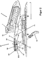
- the Figure 2 shows a rear jaw 5 of a ski binding and a ski brake 50 which is arranged in front of the rear jaw 5 in a longitudinal direction L of the ski.
- the ski brake 50 can be connected to the heel 5 so that the heel 5 and the ski brake 50 are connected to the ski as one component, or the ski brake 50 can be a separate component that can be connected to the ski independently of the heel 5 .
- the heel 4 comprises a heel holder 7 with a tread spur 71 and a sole holder 72, which is moved to a free upper side of the rear end of the ski boot sole when stepping on with the ski boot in the heel 4 in order to secure the ski boot in the ski binding.
- the ski brake 50 comprises a pedal 51 which forms a contact surface 52 for the ski boot held in the ski binding in the configuration for the descent.
- the pedal 51 is connected to brake blades 55 via a known mechanism which is not described in more detail here.
- the brake blades 55 are moved into a rest position via the mechanism, which is in the Figure 3 is shown, in which they rest on the side of the ski and can not generate a braking effect.
- the brake blades 55 can be pivoted away from the ski so that they can engage in the snow or ice in order to brake the ski.
- the ski is separated from the ski boot, for example after a fall, when the brake blades 55 can develop their braking effect.
- the ski brake 50 further comprises a brake locking element 54, with which the brake 50 in the in the Figure 3 The position shown can be locked, for example when the ski binding has the configuration for ascent, or the ski is to be transported with the binding.
- the brake locking element 54 is arranged below the contact surface 52 of the pedal 51 and can be moved linearly in the longitudinal direction L of the ski relative to the contact surface 52, as indicated by the arrows.
- the brake locking element 54 comprises a hook-shaped engaging element 56 with a nose 57 formed at the free end of the engaging element 56 which cooperates with the mechanism to secure the brake blades 55 in the configuration of the ski binding for ascent on the ski or in the configuration of the ski binding for the Release departure for braking.
- the ski brake 50 can comprise a spring element (not shown) which preloads the brake locking element 54 so that, in the configuration of the ski binding for ascent, it can automatically move into the position in which it fixes the brake blades 55 on the ski.
- the brake 50 comprises a functional element 53, the meaning of which in the description for Figure 3 is explained in more detail.
- the functional element 53 is in a pivot axis S53 with the pedal 51 and in an elongated hole 58 of the brake locking element 54 with the brake locking element 54 connected. In the position shown, the functional element 53 prevents the brake locking element 54 from being able to be displaced linearly relative to the support surface 52 of the pedal 51 in order to lock the mechanism.
- the brake 50 further comprises a climbing aid 8, which is also connected to the pedal 51 in the swivel joint formed by the swivel axis S53.
- the Figure 3 shows the heel 5 in a ski binding configuration for ascent.
- the brake pedals 55 are in the rest position and are secured in this position by the brake locking element 54, which is not visible.
- the functional element 53 was made, for example, by hand from the in FIG Figure 2 moved out position shown and is now above the contact surface 52 of the pedal 51.
- the brake locking element 54 was released now in the elongated hole 58 (see Figure 2 ) guided linearly to the contact surface 52 of the pedal 51 to intervene with the nose 57 in the movement mechanism for the brake blades 55 and thereby fix the brake blades 55 on the ski.
- the functional element 53 prevents the lower side of the ski boot sole from being lowered down to the contact surface 52 of the pedal 51 for the ascent in the configuration of the ski binding.
- the functional element 53 therefore forms a kind of first climbing aid for ascent in flat terrain.
- the functional element comprises two rollers 59 which are contacted by the underside of the ski boot sole during the ascent.
- a soft, elastic material can be used as the material of the rollers 59 in order to protect the user's joints.
- the rollers 59 can rotate on the axle that bears them, so that the functional element 53 is not loaded with unnecessary shear forces by friction, if possible.
- the heel holder 7 is shown in the open position and, when the toe piece 1 has assumed the configuration for an ascent, cannot be closed by the ski boot, since the ski boot is offset forward in the configuration for the ascent in the longitudinal direction L of the ski and therefore a rear end of the Ski boots do not contact the heel holder 7 and in particular not the tread spur 71.
- the Figure 4 shows the ski binding with the toe piece 1 with the base 2 and the heel piece 5 mounted on a ski.
- a ski boot 100 is held in the ski binding, the ski binding being in the first configuration for the descent.
- the ski brake 50 is loaded with the ski boot, so that the pedal 51 is in a lower position close to the ski surface 200 and the brake blades rest on the ski without being locked by the brake locking element 54.
- the sole underside 103 of the ski boot sole rests in the ball area on the contact plate 300 and in the heel area on the contact surface 52, the functional element 53 and the climbing aid 8 are in the respective storage positions below or level with the contact surface 52 of the pedal 51
- the contact area 52 or the sole underside 103 standing on the contact area 52 is at a height distance H1 perpendicular to the ski surface.
- the ski boot 100 assumes a first position P1 in which the heel holder 7 contacts the rear sole end 102 and the second holding device 4 contacts the front sole end.
- the ski boot 100 In the position P1, the ski boot 100 is in a rear position on the ski as seen in the longitudinal direction L of the ski, provided the heel holder 7 or the heel jaw 7 are not linearly displaceable on the ski (apart from a known length compensation in the case of a ski flex) after the ski binding was adjusted to a ski boot size, which is assumed here.
- the Figure 5 shows the ski binding of the Figure 4 with the ski boot 100 in the second configuration for the ascent.
- the functional element 53 is pivoted into its operative position, so that the ski boot 100 rests on the functional element 53 with the sole underside 103 in the heel area.
- the front sole end 101 of the ski boot is now held in the first holding device 3, the first engagement element 31 and the second engagement element 32 engage in corresponding counter-engagement elements in the front sole end 101 of the ski boot 100 and an articulation axis A1 (see FIG Figure 1 ), around which the ski boot in the ski binding is kept pivotable in the configuration for the ascent.
- the sole bottom 103 of the ski boot is in the Figure 5 , which shows the ski binding in the configuration for the ascent, does not rest on the contact plate 300 of the toe piece 1, but is held by the first holding device 3 in a position in which the sole underside 103 lies above the contact plate 300.
- the rear sole end 102 of the ski boot 100 is free to detach itself from the functional element 53 in order to be pivoted away from the ski and pivoted onto the ski or the functional element 53.
- the sole underside 103 of the ski boot 100 resting on the functional element 53 has a height distance H2 from the ski surface 200 which is greater than the height distance H1 as shown in FIG Figure 4 is shown. In the Figure 4 the height difference between the height distance H1 and the height distance H2 is shown as height compensation H21.
- the ski boot 100 takes in the Figure 5 a second position P2, in which the heel holder 7 cannot contact the rear sole end 102 and the front sole end 101 is held solely in the first holding device 3.
- the ski boot 100 was moved on the ski in the ski longitudinal direction L in the direction of the ski tip, so that it is now in position P2, a forward position on the ski.
- the positions P1 and P2 differ in that the ski boot 100 is arranged at different locations on the ski in the longitudinal direction of the ski, and at the same time a distance between the sole underside 103 and the ski surface 200 in the position P1 is different than a distance between the sole underside 103 and the ski surface 200 in the position P2.
- the different positions P1 and P2 relative to the ski are selected in such a way that they make it easier for the user to control the ski in the respective configuration and thereby increase skiing pleasure.
- the Figure 6 only differs from the Figure 5 that the climbing aid 8 now supports the rear end of the sole 102 for an ascent in steep terrain.
Landscapes
- Footwear And Its Accessory, Manufacturing Method And Apparatuses (AREA)
- Braking Elements And Transmission Devices (AREA)
- Braking Arrangements (AREA)
- Handcart (AREA)
Description
Die Erfindung betrifft eine Skibindung mit einem Vorderbacken zum Halten eines vorderen Sohlenendes eines Skischuhs und einem Hinterbacken zum Halten eines hinteren Sohlenendes des Skischuhs, wobei der Skischuh in einer ersten Konfiguration der Skibindung für die Abfahrt eine erste Position einnimmt, in welcher der Hinterbacken den Skischuh mit dem Ski verbindet, und der Skischuh in einer zweiten Konfiguration für den Aufstieg eine zweite Position einnimmt, in der der Skischuh relativ zum Hinterbacken bewegbar ist. Dabei ist der Skischuh in der ersten Position in einer Skilängsrichtung gesehen auf dem Ski weiter hinten angeordnet, als in der zweiten Position, und eine Unterseite der Skischuhsohle weist in der ersten Position einen kleineren senkrechten Abstand zu einer der Skischuhsohle zugewandten Skioberfläche auf, als in der zweiten Position.The invention relates to a ski binding with a toe piece for holding a front sole end of a ski boot and a heel piece for holding a rear sole end of the ski boot, the ski boot in a first configuration of the ski binding for the descent taking a first position in which the heel piece with the ski boot connects to the ski, and in a second configuration the ski boot assumes a second position for the ascent in which the ski boot can be moved relative to the heel. In the first position, the ski boot is arranged further back on the ski than in the second position, viewed in a longitudinal direction, and an underside of the ski boot sole has a smaller perpendicular distance to a ski surface facing the ski boot sole than in the first position second position.
Ein Beispiel für eine bereits bekannte Skibindung ist in dem Dokument
Es ist Aufgabe der Erfindung eine Skibindung bereit zu stellen, die sowohl für einen Aufstieg als auch für eine Abfahrt genutzt werden kann, wobei die Skibindung die Sicherheit und den Komfort für den Nutzer beim Aufstieg und bei der Abfahrt verbessert. Ein Aspekt der Erfindung betrifft eine Skibindung mit einem Vorderbacken zum Halten eines vorderen Sohlenendes eines Skischuhs und einem Hinterbacken zum Halten eines hinteren Sohlenendes des Skischuhs, wobei der Hinterbacken einen Fersenhalter zum Halten des hinteren Sohlenendes umfasst, und wobei der Vorderbacken umfasst:
- eine Basis, mit der der Vorderbacken mit einem Ski verbunden werden kann,
- einen Backenkörper, der mit der Basis verbunden oder verbindbar ist, oder die Basis mitbildet,
- eine erste Haltevorrichtung mit der der Skischuh am vorderen Sohlenende für einen Aufstieg mit dem Ski verbindbar ist, mit wenigstens einem ersten, bevorzugt einem ersten und einem zweiten Eingriffselement, die aus einer ersten Position, in der sie einen ersten Abstand zueinander haben, aufeinander zu in eine zweite Position bewegbar sind, in der sie einen zweiten Abstand zueinander haben, der kleiner ist, als der erste Abstand, wobei das erste Eingriffselement und das zweite Eingriffselement in der zweiten Position eine Gelenkachse definieren, um die der Skischuh mit seinem vorderen Sohlenende bei einem Aufstieg mit dem Ski verschwenkbar ist,
- eine zweite Haltevorrichtung mit der der Skischuh am vorderen Sohlenende für eine Abfahrt mit dem Ski verbindbar ist, wobei die zweite Haltevorrichtung eine erste Konfiguration für die Abfahrt aufweist, in welcher die zweite Haltevorrichtung mit dem vorderen Sohlenende des Skischuhs in Kontakt ist, und eine zweite Konfiguration für den Aufstieg aufweist, in welcher die zweite Haltevorrichtung mit dem vorderen Sohlenende des Skischuhs außer Kontakt ist,
- wobei der Skischuh in der ersten Konfiguration für die Abfahrt eine erste Position einnimmt, in welcher der Fersenhalter das hintere Sohlenende kontaktiert, und in welcher eine Sohlenunterseite einen ersten Höhenabstand zu einer Skioberfläche aufweist,
- wobei der Skischuh in der zweiten Konfiguration für den Aufstieg eine zweite Position einnimmt, in welcher der Fersenhalter das hintere Sohlenende nicht kontaktiert und in welcher die Sohlenunterseite des Skischuhs einen zweiten Höhenabstand zur Skioberfläche aufweist, und
- wobei der Skischuh in der ersten Position in einer Skilängsrichtung auf dem Ski gesehen weiter hinten angeordnet ist als in der zweiten Position und der erste Höhenabstand zu der Skioberfläche kleiner als der zweite Höhenabstand zu der Skioberfläche ist.
- a base with which the toe piece can be connected to a ski,
- a jaw body which is connected or can be connected to the base, or which forms the base,
- a first holding device with which the ski boot can be connected at the front end of the sole for an ascent with the ski, with at least a first, preferably a first and a second engagement element, which approach each other from a first position in which they are at a first distance from one another a second position are movable in which they have a second distance from one another which is smaller than the first distance, wherein the first engagement element and the second engagement element in the second position define a hinge axis around which the ski boot with its front sole end at a Ascent with the ski can be swiveled,
- a second holding device with which the ski boot can be connected to the ski at the front sole end for a descent, the second holding device having a first configuration for the descent, in which the second holding device is in contact with the front sole end of the ski boot, and a second configuration for the ascent, in which the second holding device is out of contact with the front sole end of the ski boot,
- wherein the ski boot in the first configuration for the descent assumes a first position in which the heel holder contacts the rear end of the sole and in which an underside of the sole is at a first height distance from a ski surface,
- wherein the ski boot assumes a second position for the ascent, in which the heel holder does not contact the rear sole end and in which the sole underside of the ski boot is at a second height distance from the ski surface, and
- wherein the ski boot in the first position, viewed in a longitudinal direction of the ski, is arranged further back than in the second position and the first height distance from the ski surface is smaller than the second height distance from the ski surface.
Mit anderen Worten umfasst der Vorderbacken der Skibindung zwei bevorzugt separate Haltevorrichtungen, nämlich die erste Haltevorrichtung und die zweite Haltevorrichtung, von denen die erste Haltevorrichtung hergerichtet ist, den Skischuh an seinem vorderen Sohlenende so zu greifen, dass der Skischuh relativ zum Ski um eine quer zur Skilängsrichtung gerichteten Achse für den Aufstieg verschwenkt werden kann. Das vordere Ende ist dabei in der Achse relativ zum Vorderbacken fixiert, so dass der Skischuh relativ zum Ski nicht linear in und gegen die Skilängsrichtung verschoben werden kann. Das hintere Ende der Skischuhsohle kann frei bewegt werden, insbesondere beim Gehen von der Skioberseite weg- und an die Skioberseite angeschwenkt werden. Bei der ersten Haltevorrichtung kann es sich beispielsweise um den Vorderbacken einer sogenannten Pinbindung handeln, mit Pins als Eingriffselementen, die in entsprechenden Öffnungen seitlich an der Skischuhsohle, die Gegeneingriffselemente zu den Eingriffselementen bilden, eingreifen können, um den Skischuh am vorderen Sohlenende sicher aber um die genannte Achse verschwenkbar in der Skibindung zu halten.In other words, the toe piece of the ski binding comprises two preferably separate holding devices, namely the first holding device and the second holding device, of which the first holding device is designed to grip the ski boot at its front sole end in such a way that the ski boot is relative to the ski by a transverse to Axis oriented in the longitudinal direction of the ski can be pivoted for the ascent. The front end is fixed in the axis relative to the toe piece, so that the ski boot cannot be displaced linearly in and against the longitudinal direction of the ski relative to the ski. The rear end of the ski boot sole can be moved freely, in particular when walking away from the top of the ski and pivoted towards the top of the ski. The first holding device can be, for example, the toe piece of a so-called pin binding, with pins as engagement elements that can engage in corresponding openings on the side of the ski boot sole, which form counter-engagement elements to the engagement elements, in order to secure the ski boot at the front end of the sole to keep said axis pivotable in the ski binding.
Die zweite Haltevorrichtung für das vordere Sohlenende des Skischuhs kommt nur zum Einsatz, wenn die Skibindung für die Abfahrt benutzt wird. Sie kann mit der Basis oder der ersten Haltevorrichtung lösbar verbunden sein, so dass sie beispielsweise für den Aufstieg abgenommen und in der Tasche oder im Rucksack mitgeführt werden kann. In der Konfiguration der Skibindung für den Aufstieg muss die zweite Haltevorrichtung (wenn nicht abgenommen) gesichert sein, so dass sie sich relativ zum Ski und der Basis des Vorderbackens nicht bewegen kann.The second holding device for the front end of the sole of the ski boot is only used when the ski binding is used for the descent. It can be detachably connected to the base or to the first holding device so that it can be removed, for example, for the ascent and carried in the pocket or backpack. In the configuration of the ski binding for ascent, the second retaining device (if not removed) must be secured so that it cannot move relative to the ski and the base of the toe piece.
Die zweite Haltevorrichtung kann aus der Stand-by Position, die sie in der Aufstiegskonfiguration der Skibindung einnimmt, in eine Sicherungsposition für die Abfahrt bewegt werden, in der die zweite Haltvorrichtung eine freie Oberseite des vorderen Skischuhsolenendes von oben und/oder seitlich umgreift, um den Skischuh im Vorderbacken zu sichern. Um die zweite Haltevorrichtung in die Sicherungsposition zu bewegen, muss bevorzugt die erste Haltevorrichtung geöffnet werden, so dass der Skischuh nicht länger in der Skibindung gehalten wird und folglich relativ zum Ski in eine beliebige Richtung bewegt werden kann. Die erste Haltevorrichtung kann jetzt ebenfalls geschlossen werden und bildet im geschlossenen Zustand, indem die Eingriffselemente in an der zweiten Haltevorrichtung ausgebildete Gegeneingriffselemente eingreifen, eine Sicherung für die zweite Haltevorrichtung, die verhindert, dass sich die zweite Haltevorrichtung ungewollt öffnet. Ist die zweite Haltevorrichtung in der Sicherungsposition, kann der Nutzer mit der vorderen Skischuhspitze in den Vorderbacken einsteigen und, wie bekannt, durch Absenken des Skischuhs in die Bindung den Hinterbacken in eine Sicherungsposition bewegen.The second holding device can be moved from the stand-by position, which it assumes in the ascent configuration of the ski binding, into a securing position for the descent, in which the second holding device engages around a free upper side of the front ski boot sole end from above and / or to the side To secure the ski boot in the toe piece. In order to move the second holding device into the securing position, the first holding device must preferably be opened so that the ski boot is no longer held in the ski binding and can consequently be moved in any direction relative to the ski. The first holding device can now also and in the closed state, in that the engagement elements engage in counter-engagement elements formed on the second holding device, forms a safety device for the second holding device, which prevents the second holding device from opening unintentionally. If the second holding device is in the securing position, the user can step into the toe piece with the front ski boot tip and, as is known, move the heel piece into a securing position by lowering the ski boot into the binding.
Die Unterseite des vorderen Sohlendes weist, wenn die Sohlenunterseite im Wesentlichen parallel zu der Oberseite des Skis liegt oder auf einer Aufstandsfläche des Hinterbackens aufliegt, in der Aufstiegsposition, in der der Skischuh nur in der ersten Haltevorrichtung gehalten wird, einen größeren Abstand zu einer Oberseite des Skis auf, als in der Abfahrtposition, in der das vordere Ende von der zweiten Haltevorrichtung gehalten und diese bevorzugt durch die erste Haltevorrichtung in der Sicherungs- oder Verschlussposition gesichert ist.If the lower side of the sole is essentially parallel to the upper side of the ski or rests on a contact surface of the heel, the lower side of the front sole end has a greater distance from an upper side of the in the climbing position in which the ski boot is only held in the first holding device Skis on than in the downhill position, in which the front end is held by the second holding device and this is preferably secured by the first holding device in the securing or locking position.
Der Hinterbacken umfasst eine Bremse mit einem Pedal, welches eine Aufstandsfläche für den Skischuh bildet, und kann zudem wenigstens eine Bremsschaufel, die zum Abbremsen des von Skischuh gelösten Skis in den Schnee eingreifen kann, umfassen. Pedal und Bremsschaufel sind in bekannter Weise miteinander verbunden, so dass die Bremsschaufel seitlich am Ski anliegt, wenn das Pedal belastet ist. Das Pedal umfasst ferner ein Funktionselement, das relativ zu der Aufstandsfläche, die das Pedal bildet, bewegbar ist, und zwar von einer ersten Lage, in der das Funktionselement außer Kontakt mit einem in der Skibindung eingesetztem Skischuh respektive eine Sohlenunterseite des Skischuhs ist und der Fersenhalter bevorzugt auf das hintere Sohlenende einwirken kann, in eine zweite Lage, in der das Funktionselement in Kontakt mit dem in der Skibindung eingesetzten Skischuh ist und der Fersenhalter bevorzugt keine Wirkung mehr auf das hintere Sohlenende des Skischuhs hat.The heel block comprises a brake with a pedal, which forms a contact surface for the ski boot, and can also comprise at least one brake blade which can engage in the snow to brake the ski released from the ski boot. The pedal and the brake blade are connected to one another in a known manner, so that the brake blade rests on the side of the ski when the pedal is loaded. The pedal further comprises a functional element that is movable relative to the contact surface that the pedal forms, namely from a first position in which the functional element is out of contact with a ski boot inserted in the ski binding or a sole underside of the ski boot and the heel holder can preferably act on the rear end of the sole, in a second position in which the functional element is in contact with the ski boot used in the ski binding and the heel holder preferably no longer has any effect on the rear end of the sole of the ski boot.
Das kann heißen, dass das Funktionselement in der ersten Lage an dem Pedal so angeordnet ist, dass es nicht über die Aufstandsfläche in Richtung der Sohlenunterseite des Skischuhs vorsteht, wenn dieser auf der Aufstandsfläche steht, und in der zweiten Lage relativ zu der Aufstandsfläche so angeordnet ist, dass die Unterseite der Skischuhsole auf dem Funktionselement aufsitzt, und nicht bis auf die Aufstandsfläche abgesenkt werden kann. Bevorzugt ist das Funktionselement so ausgebildet, dass es in der zweiten Lage eine Höhendifferenz zwischen dem zweiten Höhenabstand und dem ersten Höhenabstand ausgleicht.This can mean that the functional element is arranged in the first position on the pedal in such a way that it does not protrude over the contact surface in the direction of the sole underside of the ski boot when the latter is on the contact surface, and in the second position Position is arranged relative to the contact surface so that the bottom of the ski boot sole rests on the functional element and cannot be lowered down to the contact surface. The functional element is preferably designed in such a way that it compensates for a height difference between the second height distance and the first height distance in the second position.
Das Funktionselement kann beispielsweise in einem Drehgelenk schwenkbar mit dem Pedal der Skibremse verbunden sein und kann durch ein Federelement in die zweite Lage vorgespannt sein, so dass das Funktionselement automatisch die zweite Lage einnimmt, wenn das Pedal druckfrei ist. Bevorzugt kann das Funktionselement in der zweiten Lage so angeordnet und/oder gesichert sein, dass es sich nicht von selbst, das heißt, ohne aktiven Eingriff des Skinutzers, aus der zweiten Lage in die erste Lage bewegen kann. Bevorzugt kann die Verstellung von der ersten Lage in die zweite Lage aktiv vom Skinutzer zum Beispiel von Hand erfolgen, wodurch auf das Federelement verzichtet werden kann, was Gewicht spart und mögliche Schadensquellen reduziert. Das Funktionselement kann wenigstens in der ersten Lage zum Beispiel durch Formschluss und/oder Kraftschluss gegen ungewolltes Lösen gesichert sein.The functional element can, for example, be pivotably connected to the pedal of the ski brake in a swivel joint and can be biased into the second position by a spring element so that the functional element automatically assumes the second position when the pedal is depressurized. The functional element can preferably be arranged and / or secured in the second position in such a way that it cannot move from the second position into the first position by itself, that is, without active intervention by the skin user. The adjustment from the first position to the second position can preferably be carried out actively by the skin user, for example by hand, whereby the spring element can be dispensed with, which saves weight and reduces possible sources of damage. The functional element can be secured against unintentional loosening at least in the first position, for example by means of a form fit and / or force fit.
Das Funktionselement kann eine Auflage, zum Beispiel eine rollenförmige Auflage, für die Sohlenunterseite des Skischuhs umfassen, die in einem Drehgelenk mit einem Funktionselementkörper verbunden ist, so dass bei Aufstieg durch den Skischuh, beim Aufsetzen und Abheben vom Funktionselement, keine Reibungskräfte auf das Funktionselement einwirken.The functional element can comprise a support, for example a roller-shaped support, for the underside of the sole of the ski boot, which is connected to a functional element body in a swivel joint, so that when climbing through the ski boot, when putting on and lifting off the functional element, no frictional forces act on the functional element .
Das Funktionselement kann in der zweiten Lage bevorzugt eine erste Steig- oder Gehhilfe bildet, für einen geringen Höhenausgleich von gleich oder kleiner 3°, bevorzugt gleich oder größer als 0°. Insbesondere kann der Höhenausgleich so ausgebildet sein, dass die in der ersten Haltevorrichtung gehaltene und auf dem Funktionselement aufstehende Skischuhsole mit ihrer Unterseite im Wesentliche parallel zu einer Skioberseite ausgerichtet ist. Das Funktionselement kann auch so ausgebildet sein, dass es in sich verstellbar ist und in jeder eingenommenen Position gesichert werden kann, wodurch der Höhenausgleich mit Hilfe des Funktionselements zumindest im Umfang von zum Beispiel 1° bis 5° verstellt werden kann, wenn sich die Geländeform entsprechend ändert.In the second layer, the functional element can preferably form a first climbing or walking aid, for a slight height compensation of equal to or less than 3 °, preferably equal to or greater than 0 °. In particular, the height compensation can be designed in such a way that the lower side of the ski boot sole held in the first holding device and standing on the functional element is oriented essentially parallel to the upper side of the ski. The functional element can also be designed in such a way that it is adjustable in itself and can be secured in any position it occupies, whereby the height compensation with the aid of the functional element at least in the Circumference can be adjusted from 1 ° to 5 °, for example, if the terrain changes accordingly.
Die Bremse weist weiterhin ein Bremsverriegelungselement auf, das zwischen einer ersten Position, in der eine Bremsschaufel zum Abbremsen des Skis freigegeben ist oder freigegeben werden kann, und einer zweiten Position, in der die Bremsschaufel in einer Nichtbremsstellung festgelegt ist oder festgelegt werden kann, hin und her bewegbar ist. Das Bremsverriegelungselement ist mit dem Funktionselement so gekoppelt, dass das Bewegen des Funktionselements aus der ersten Lage in die zweite Lage das Bremsverriegelungselement frei gibt sich aus der ersten Position in die zweite Position zu bewegen.The brake furthermore has a brake locking element that switches between a first position, in which a brake blade is or can be released for braking the ski, and a second position, in which the brake blade is fixed or can be fixed in a non-braking position is movable forward. The brake locking element is coupled to the functional element in such a way that moving the functional element from the first position into the second position enables the brake locking element to move from the first position into the second position.
Dazu kann das Bremsverriegelungselement mit einer Unterseite des Pedals so verbunden sein, dass es relativ zum Pedals linear in und gegen die Skilaufrichtung verschoben werden kann. Das Bremsverriegelungselement kann ein hakenförmiges Eingriffselement aufweisen, das vom Pedal im Wesentlichen senkrecht nach unten vorsteht, mit einer in Skilaufrichtung vorstehenden Nase am freien Ende des Hakens, die in der zweiten Position die Bremsschaufeln verriegelt, so dass diese nicht zum Bremsen vom Ski in Richtung der Fahrunterlage, wie Eis oder Schnee, abgeschwenkt werden können.For this purpose, the brake locking element can be connected to an underside of the pedal in such a way that it can be displaced linearly in and against the skiing direction relative to the pedal. The brake locking element can have a hook-shaped engagement element that protrudes from the pedal essentially vertically downwards, with a protruding nose in the skiing direction at the free end of the hook, which locks the brake blades in the second position so that they are not used to brake the ski in the direction of the Driving surface, such as ice or snow, can be swiveled away.
Die zweite Haltevorrichtung kann in der ersten Konfiguration für die Abfahrt mit der Basis und/oder der ersten Haltevorrichtung gekoppelt sein, und die zweite Haltevorrichtung kann relativ zur ersten Haltevorrichtung um eine Schwenkachse zwischen der Konfiguration für die Abfahrt und der Konfiguration für den Aufstieg verschwenkbar sein. Die Schwenkachse kann insbesondere an einem in Skilaufrichtung vorderen Ende der Basis des Vorderbackens gebildet sein, das heißt, in Skilängsrichtung vor dem in der Bindung gehaltenen Skischuh.The second holding device can be coupled to the base and / or the first holding device in the first configuration for the descent, and the second holding device can be pivotable relative to the first holding device about a pivot axis between the configuration for the descent and the configuration for the ascent. The pivot axis can in particular be formed at a front end of the base of the toe piece in the skiing direction, that is to say in front of the ski boot held in the binding in the longitudinal direction of the ski.
In der Konfiguration für die Abfahrt, das heißt, wenn die zweite Haltevorrichtung bevorzugt auf die vordere freie Oberseite der Skischuhsohle einwirkt und durch die erste Haltevorrichtung gegen ein ungewolltes Öffnen gesichert werden kann, kann die Schwenkachse, in der das erste Halteelement mit dem zweiten Halteelement verbunden ist, in Skilängsrichtung gesehen in einem ersten Längsabstand vor der Gelenkachse, die das erste Eingriffselement und das zweite Eingriffselement definieren, angeordnet sein, und eine Anlagefläche für das vordere Sohlenende kann in einem zweiten Längsabstand von der Schwenkachse angeordnet sein, wobei der erste Längsabstand kleiner als der zweite Längsabstand ist. Die Längendifferenz zwischen dem ersten Längsabstand und dem zweiten Längsabstand bewirkt einen Längsversatz des Skischuhs zwischen der ersten Position für die Abfahrt und der zweiten Position für den Aufstieg, wobei in der ersten Position das vordere Ende der Skischuhsohle weiter entfernt von einer Skispitze ist, als in der zweiten Position. Der Vorderbacken und der Hinterbacken werden für den Positionswechsel relativ zum Ski nicht bewegt.In the configuration for the descent, that is, when the second holding device preferably acts on the front free upper side of the ski boot sole and can be secured against unintentional opening by the first holding device, the Pivot axis, in which the first holding element is connected to the second holding element, viewed in the longitudinal direction of the ski, can be arranged at a first longitudinal distance in front of the joint axis defining the first engagement element and the second engagement element, and a contact surface for the front sole end can be arranged at a second longitudinal distance be arranged from the pivot axis, wherein the first longitudinal distance is smaller than the second longitudinal distance. The difference in length between the first longitudinal distance and the second longitudinal distance causes a longitudinal offset of the ski boot between the first position for the descent and the second position for the ascent, with the front end of the ski boot sole being further away from a ski tip than in the first position second position. The toe and heel are not moved relative to the ski when changing position.
Der Basis oder dem Vorderbacken kann ferner eine Aufstandsplatte zugeordnet sein, welche in der Konfiguration für den Aufstieg durch die Höhendifferenz zwischen dem zweiten Höhenabstand und dem ersten Höhenabstand vom Skischuh nicht kontaktiert wird. In der Konfiguration für die Abfahrt kann die Aufstandsplatte eine Seitensicherheitsauslösung der Skibindung unterstützen.The base or the toe piece can also be assigned a support plate which, in the configuration for the ascent, is not contacted by the ski boot due to the difference in height between the second height distance and the first height distance. In the configuration for the descent, the contact plate can support a side safety release of the ski binding.
Die Skibindung kann neben dem Funktionselement, das eine erste Steighilfe für flaches Gelände bilden kann, eine weitere Steighilfe oder zwei oder mehr weitere Steighilfen umfassen, die aus einer Ruhestellung, in der sie ein Position einnehmen, die in der Konfiguration der Skibindung für die Abfahrt nicht stört, in eine Funktionsstellung bewegt werden kann/können, in der sie den Skischuh für einen Höhenausgleich beispielweise von größer 3°, zum Beispiel 6° oder 10° oder einem anderen Wert, abstützt.In addition to the functional element, which can form a first climbing aid for flat terrain, the ski binding can comprise a further climbing aid or two or more further climbing aids that are not in the configuration of the ski binding for the descent from a rest position in which they assume a position disturbs, can / can be moved into a functional position in which it supports the ski boot for height compensation, for example greater than 3 °, for example 6 ° or 10 ° or another value.
Im Folgenden wird ein Ausführungsbeispiel der Erfindung anhand von Figuren näher erläutert, ohne dass die Erfindung dadurch auf das gezeigt Ausführungsbeispiel beschränkt ist. Den Umfang der Erfindung definieren die Ansprüche.In the following, an exemplary embodiment of the invention is explained in more detail with reference to figures, without the invention being thereby restricted to the exemplary embodiment shown. The scope of the invention is defined by the claims.
Die Figuren zeigen im Einzelnen:
- Figur 1:
- Vorderbacken mit erster Haltevorrichtung und zweiter Haltevorrichtung;
- Figur 2:
- Hinterbacken mit ausgelöster Skibremse;
- Figur 3:
- Hinterbacken mit Skibremse für einen Aufstieg gesichert;
- Figur 4:
- Skibindung in der Konfiguration für eine Abfahrt;
- Figur 5:
- Skibindung in der Konfiguration für einen Aufstieg in flachem Gelände;
- Figur 6:
Skibindung der Figur 5 für Aufstieg in steilem Gelände.
- Figure 1:
- Toe piece with first holding device and second holding device;
- Figure 2:
- Heel jaws with released ski brake;
- Figure 3:
- Heel secured with ski brake for an ascent;
- Figure 4:
- Ski binding in the configuration for one descent;
- Figure 5:
- Ski binding configured for an ascent in flat terrain;
- Figure 6:
- Ski binding of the
Figure 5 for ascent in steep terrain.
Die
Die beiden aufeinander zu geschwenkten Eingriffselemente 31, 32 definieren eine Gelenkachse A1, in der ein in der Skibindung gehaltene Skischuh für den Aufstieg rotatorisch bewegt werden kann, so dass eine Ferse des Skischuhs vom Ski abgehoben und auf den Ski abgesenkt werden kann.The two
Der Vorderbacken 1 umfasst ferner eine zweite Haltevorrichtung 4 mit einer Anlagefläche 48 für ein vorderes Ende einer Skischuhsohle des in der Skibindung gehaltenen Skischuhs, um den Skischuh in einer ersten Konfiguration der Skibindung für die Abfahrt sicher mit dem Ski zu verbinden. Die zweite Haltevorrichtung 4 ist mit der ersten Haltevorrichtung 3 in einem Schwenkgelenk mit einer Schwenkachse S34 verbunden, so dass die zweite Haltevorrichtung 4 aus der gezeigten Position so verschwenkt werden kann, dass die Anlagefläche 48 in eine Position bewegt wird, in der sie mit dem vorderen Ende des in der Skibindung gehaltenen Skischuhs in Kontakt ist.The toe piece 1 further comprises a
Ein erster Längsabstand L1 zwischen der Schwenkachse 34, die die erste Haltevorrichtung 3 schwenkbar mit der zweiten Haltevorrichtung 4 verbindet, und der Gelenkachse A1, die die Eingriffselemente 31, 32 der ersten Haltevorrichtung 3 bilden, ist im Wesentlichen konstant, egal ob die Skibindung in der Konfiguration für die Abfahrt oder in der Konfiguration für den Aufstieg ist. In der Konfiguration für die Abfahrt ist der erste Längenabstand L1 kleiner als ein zweiter Längenabstand L2 zwischen der Schwenkachse S34 und einer Anlagefläche 48 für das vordere Sohlenende des Skischuhs an der zweiten Haltevorrichtung 4. Der zweite Längenabstand L2 ist in der
Ist die zweite Haltevorrichtung 4 in der nicht gezeigten angeschwenkten Position, kann sie in dieser Position durch die erste Haltevorrichtung 3 gesichert werden, indem das erste Eingriffselement 31 und das zweite Eingriffselement 32 in entsprechende Gegeneingriffselemente, die von der zweiten Haltevorrichtung 4 umfasst sind, eingreifen und die erste Haltevorrichtung 3 in bekannte Weise durch eine mittels eines Spannhebels 33 im Eingriff mit der zweiten Haltevorrichtung 4 gesichert wird.If the
Der Vorderbacken 1 umfasst ferner eine Aufstandsplatte 300, auf der der Skischuh mit seiner Sohlenunterseite im Ballenbereich in der Konfiguration für die Abfahrt aufstehen kann.The toe piece 1 further comprises a
Die
Der Hinterbacken 4 umfasst einen Fersenhalter 7 mit einem Trittsporn 71 und einem Sohlenhalter 72, der beim Einsteigen mit dem Skischuh in den Hinterbacken 4 auf eine freie Oberseite des hinteren Endes der Skischuhsohle bewegt wird, um den Skischuh in der Skibindung zu sichern.The
Die Skibremse 50 umfasst ein Pedal 51, das eine Aufstandsfläche 52 für den in der Skibindung in der Konfiguration für die Abfahrt gehaltenen Skischuh bildet. Das Pedal 51 ist über ein bekannte Mechanik, die hier nicht näher beschrieben wird, mit Bremsschaufeln 55 verbunden. Über die Mechanik werden die Bremsschaufeln 55 bei belastetem Pedal 51 in eine Ruhestellung bewegt, die in der
Die Skibremse 50 umfasst ferner ein Bremsverriegelungselement 54, mit dem die Bremse 50 in der in der
Schließlich umfasst die Bremse 50 ein Funktionselement 53, dessen Bedeutung in der Beschreibung zur
Die Bremse 50 umfasst weiterhin eine Steighilfe 8, die mit dem Pedal 51 ebenfalls in dem von der Schwenkachse S53 mit gebildeten Schwenkgelenk verbunden ist.The
Die
Das Funktionselement 53 verhindert, dass in der Konfiguration der Skibindung für den Aufstieg die Unterseite der Skischuhsohle bis auf die Aufstandsfläche 52 des Pedals 51 abgesenkt werden kann. Das Funktionselement 53 bildet daher eine Art erste Steighilfe für den Aufstieg in flachem Gelände. Im Ausführungsbeispiel umfasst das Funktionselement zwei Rollen 59 die von der Unterseite der Skischuhsohle beim Aufstieg kontaktiert werden. Als Material der Rollen 59 kann ein weiches elastisches Material benutzt werden, um die Gelenke des Nutzers zu schonen. Die Rollen 59 können auf der sie tragenden Achse rotieren, so dass das Funktionselement 53 möglichst nicht durch Reibung mit unnötigen Scherkräften belastet wird.The
Der Fersenhalter 7 ist in der offenen Position dargestellt und kann, wenn der Vorderbacken 1 die Konfiguration für einen Aufstieg eingenommen hat, nicht durch den Skischuh geschlossen werden, da der Skischuh in der Konfiguration für den Aufstieg in Skilängsrichtung L nach vorne versetzt ist und demnach ein hinteres Sohlenende des Skischuhs nicht den Fersenhalter 7 und insbesondere nicht den Trittsporn 71 kontaktiert.The
Die
Der Skischuh 100 nimmt eine erste Position P1 ein, in der der Fersenhalter 7 das hintere Sohlenende 102 und die zweite Haltevorrichtung 4 das vordere Sohlenende kontaktiert. In der Position P1 ist der Skischuh 100 in der Skilängsrichtung L gesehen in einer hinteren Position auf dem Ski, vorausgesetzt der Fersenhalter 7 oder der Hinterbacken 7 sind auf dem Ski nicht linear verschiebbar (abgesehen von einem bekannten Längenausgleich bei einem Skiflex), nachdem die Skibindung auf eine Skischuhgröße eingestellt wurde, wovon hier ausgegangen wird.The
Die
Wie bei einem Vergleich der
Das hintere Sohlende 102 des Skischuhs 100 ist frei sich von dem Funktionselement 53 zu lösen, um vom Ski abgeschwenkt und an den Ski respektive das Funktionselement 53 angeschwenkt zu werden. Die auf dem Funktionselement 53 aufsitzende Sohlenunterseite 103 des Skischuhs 100 hat einen Höhenabstand H2 zur Skioberfläche 200 der größer ist als der Höhenabstand H1, wie er in der
Der Skischuh 100 nimmt in der
Im Vergleich der
Die unterschiedlichen Positionen P1 und P2 relativ zum Ski sind so gewählt, dass sie das Beherrschen des Skis durch den Nutzer in der jeweiligen Konfiguration erleichtern und dadurch die Fahrfreude steigern.The different positions P1 and P2 relative to the ski are selected in such a way that they make it easier for the user to control the ski in the respective configuration and thereby increase skiing pleasure.
Die
- 11
- VorderbackenToe piece
- 22
- BasisBase
- 33
- erste Haltevorrichtungfirst holding device
- 3131
- erstes Eingriffselementfirst engagement element
- 3232
- zweites Eingriffselementsecond engagement element
- 3333
- SpannhebelTension lever
- 44th
- zweite Haltevorrichtungsecond holding device
- 4848
- AnlageflächeContact surface
- 55
- HinterbackenButtocks
- 5050
- Bremsebrake
- 5151
- Pedalpedal
- 5252
- AufstandsflächeFootprint
- 5353
- FunktionselementFunctional element
- 5454
- BremsverriegelungselementBrake locking element
- 5555
- BremsschaufelBrake blade
- 5656
- EingriffselementEngagement element
- 5757
- Nasenose
- 5858
- LanglochLong hole
- 5959
- Rolle, rollenförmige AuflageRoll, roll-shaped support
- 77th
- FersenhalterHeel holder
- 7171
- TrittspornTread spur
- 88th
- SteighilfeClimbing aid
- 100100
- SkischuhSki boot
- 101101
- vorderes Sohlenendefront end of the sole
- 102102
- hinteres Sohlenenderear end of the sole
- 103103
- SohlenunterseiteSole underside
- 200200
- SkioberflächeSki surface
- 300300
- AufstandsplatteUprising plate
- A1A1
- GelenkachseJoint axis
- A2A2
- Achseaxis
- L1L1
- erster Längsabstandfirst longitudinal distance
- L2L2
- zweiter Längsabstandsecond longitudinal distance
- H1H1
- erster Höhenabstandfirst height distance
- H2H2
- zweiter Höhenabstandsecond height distance
- H21H21
- HöhenausgleichHeight adjustment
- P1P1
- erste Positionfirst position
- P2P2
- zweite Positionsecond position
- S34S34
- SchwenkachseSwivel axis
- S53S53
- SchwenkachseSwivel axis
- LL.
- SkilängsrichtungLongitudinal direction of the ski
Claims (13)
- A ski binding, comprising: a front jaw (1) for holding a front end (101) of the sole of a ski boot (100); and a rear jaw (5) for holding a rear end (102) of the sole of the ski boot (100), wherein the rear jaw (5) comprises a heel retainer (7) for holding the rear end (102) of the sole, and wherein the front jaw (1) comprises:• a base (2) via which the front jaw (1) can be connected to a ski;• a jaw body which is or can be connected to the base (2) or which forms part of the base (2);• a first holding device (3), via which the ski boot (100) can be connected to the ski at the front end (101) of the sole for ascending, comprising a first and a second engaging element (31, 32) which can be moved towards each other from a first position, in which they are at a first distance from each other, to a second position in which they are at a second distance from each other, wherein the second distance is smaller than the first distance, wherein in the second position, the first engaging element (31) and the second engaging element (32) define a joint axis (A1) about which the front end of the sole of the ski boot can be pivoted when ascending in skis; and• a second holding device (4), via which the ski boot (100) can be connected to the ski at the front end (101) of the sole for descending, wherein the second holding device (4) exhibits a first configuration for descending, in which the second holding device (4) is in contact with the front end (101) of the sole of the ski boot (100), and a second configuration for ascending in which the second holding device (4) is out of contact with the front end (101) of the sole of the ski boot (100),wherein in the first configuration for descending, the ski binding holds the ski boot (100) in a first position (P1) in which the rear end (102) of the sole is contacted by the heel retainer (7) and in which a lower side (103) of the sole of the ski boot (100) is held at a first vertical distance (H1) from a surface (200) of the ski,wherein in the second configuration for ascending, the ski binding holds the ski boot (100) in a second position (P2) in which the rear end (102) of the sole is not contacted by the heel retainer (7) and in which the lower side (103) of the sole of the ski boot (100) is held at a second vertical distance (H2) from the surface of the ski (200), wherein in the first position (P1), the ski boot (100) is arranged further back on the ski as viewed in a longitudinal direction (L) of the ski than in the second position (P2), and the first vertical distance (H1) from the surface (200) of the ski is smaller than the second vertical distance (H2) from the surface (200) of the ski, wherein the rear jaw (5) comprises a brake (50), comprising a pedal (51) which forms a bearing area (52) for the ski boot (100), and a functional element (53) which can be moved relative to the bearing area (52) from a first location, in which the functional element (53) is out of contact with a ski boot (100) which is inserted in the ski binding, to a second location in which the functional element (53) is in contact with the ski boot (100) which is inserted in the ski binding, and wherein in the second location, the functional element (53) compensates for the difference in height (H21) of the lower side (103) of the sole at the front end (101) of the sole between the second vertical distance (H2) and the first vertical distance (H1) in the region of the lower side (103) of the sole at the rear end (102) of the sole,characterised in thatthe brake (50) comprises a brake locking element (54) which is coupled to the functional element (53) such that the functional element (53) locks the brake locking element (54) for ascending in the second location and releases the brake locking element (54) for descending in the first location.
- The ski binding according to claim 1, wherein in the second location, the functional element (53) lies above the bearing area (52) and preferably forms a first walking aid for a height adjustment equal to or less than 3°, preferably equal to or greater than 0°.
- The ski binding according to any one of the preceding claims, wherein the brake locking element (54) can be moved back and forth between a first position, in which a brake paddle (55) can be released in order to slow down the ski, and a second position in which the brake paddle (55) can be fixed in a non-braking position, wherein moving the functional element (53) releases the brake locking element (54) for moving from the first position to the second position.
- The ski binding according to any one of the preceding claims, wherein in the first configuration for descending, the second holding device (4) is coupled to the base (2) and/or to the first holding device (3) and can be pivoted relative to the first holding device (3) about a pivot axis (S34) between the first configuration for descending and the second configuration for ascending.
- The ski binding according to the preceding claim, wherein in the first configuration for descending, the pivot axis (S34) is arranged at a first longitudinal distance (L1) in front of the joint axis (A1) as viewed in the longitudinal direction (L) of the ski, and an abutting area (48) for the front end (101) of the sole is arranged at a second longitudinal distance (L2) from the pivot axis (S23) as viewed in the longitudinal direction (L) of the ski, wherein the first longitudinal distance (L1) is smaller than the second longitudinal distance (L2).
- The ski binding according to the preceding claim, wherein a difference in length between the first longitudinal distance (L1) and the second longitudinal distance (L2) causes a longitudinal offset of the ski boot (100) between the first position (P1) and the second position (P2) on the ski.
- The ski binding according to any one of the preceding claims, wherein the base (2) is also assigned a bearing plate (300) which is not contacted by the ski boot (100) in the second configuration for ascending due to a difference in height (H21) between the second vertical distance (H2) and the first vertical distance (H1).
- The ski binding according to any one of the preceding claims, wherein the functional element (53) comprises a roller-shaped bearing support (59), which is rotatably mounted on an axis (A53) for the lower side (103) of the sole of the ski boot (100).
- The ski binding according to any one of the preceding claims, wherein the first holding device (3) and the second holding device (4) are releasably connected to each other.
- The ski binding according to any one of the preceding claims, wherein in the first configuration for descending, the first holding device (3) secures the second holding device (4) in that the at least first securing element (31) engages with a corresponding complementary engaging element of the second holding device (4) or in that the first securing element (31) and the second securing element (32) engage with corresponding complementary engaging elements of the second holding device (4).
- The ski binding according to any one of the preceding claims, wherein the brake (50) comprises a climbing aid (8) for ascending in steep terrain.
- The ski binding according to the preceding claim, wherein the functional element (53) and the climbing aid (8) are pivotably connected to the brake (50), preferably to the pedal (51), in a common pivot axis (S53).
- The ski binding according to any one of the preceding claims, wherein the front jaw (1) and the rear jaw (5) can be fixedly mounted on the ski and cannot be linearly moved and/or pivoted relative to the ski.
Applications Claiming Priority (1)
| Application Number | Priority Date | Filing Date | Title |
|---|---|---|---|
| DE102019108350.8A DE102019108350A1 (en) | 2019-03-29 | 2019-03-29 | Braking device |
Publications (2)
| Publication Number | Publication Date |
|---|---|
| EP3714951A1 EP3714951A1 (en) | 2020-09-30 |
| EP3714951B1 true EP3714951B1 (en) | 2021-12-01 |
Family
ID=68424820
Family Applications (2)
| Application Number | Title | Priority Date | Filing Date |
|---|---|---|---|
| EP19206528.2A Active EP3714951B1 (en) | 2019-03-29 | 2019-10-31 | Ski bindings |
| EP20164734.4A Pending EP3714952A1 (en) | 2019-03-29 | 2020-03-20 | Braking device |
Family Applications After (1)
| Application Number | Title | Priority Date | Filing Date |
|---|---|---|---|
| EP20164734.4A Pending EP3714952A1 (en) | 2019-03-29 | 2020-03-20 | Braking device |
Country Status (3)
| Country | Link |
|---|---|
| US (1) | US11154764B2 (en) |
| EP (2) | EP3714951B1 (en) |
| DE (1) | DE102019108350A1 (en) |
Families Citing this family (1)
| Publication number | Priority date | Publication date | Assignee | Title |
|---|---|---|---|---|
| FR3141075A1 (en) * | 2022-10-21 | 2024-04-26 | Skis Rossignol | Braking device for a sliding board |
Family Cites Families (59)
| Publication number | Priority date | Publication date | Assignee | Title |
|---|---|---|---|---|
| DE2906726A1 (en) * | 1979-02-21 | 1980-10-23 | Marker Hannes | HEEL TIGHTS FOR SAFETY SKI BINDINGS |
| AT368018B (en) * | 1979-10-25 | 1982-08-25 | Tyrolia Freizeitgeraete | SKI BRAKE |
| DE3048175A1 (en) * | 1980-12-19 | 1982-07-22 | Heinrich Wunder GmbH & Co KG, 8060 Dachau | TOUR BINDING WITH SKISTOPPER |
| DE3110743A1 (en) * | 1981-03-19 | 1982-10-07 | Hannes Marker Sicherheits-Skibindungen GmbH & Co KG, 8100 Garmisch-Partenkirchen | SKISTOPPER |
| DE3265951D1 (en) * | 1981-03-27 | 1985-10-10 | Tmc Corp | Ski brake |
| DE3116039A1 (en) * | 1981-04-22 | 1983-10-06 | Marker Patentverwertungs Gmbh | Ski-stopper |
| DE3131917C2 (en) * | 1981-08-12 | 1995-07-13 | Marker Int | Heel tensioner for a ski binding with integrated ski brake |
| AT372007B (en) * | 1981-09-18 | 1983-08-25 | Tyrolia Freizeitgeraete | SKI BRAKE |
| DE3140819A1 (en) * | 1981-10-13 | 1983-04-21 | ess GmbH Skibindungen, 8978 Burgberg | SKI BRAKE |
| DE3145646A1 (en) * | 1981-11-17 | 1983-05-26 | Marker Patentverwertungsgesellschaft mbH, 6340 Baar | SKISTOPPER |
| FR2541124A1 (en) * | 1983-02-23 | 1984-08-24 | Salomon & Fils F | LOCKING DEVICE FOR SKI BRAKE |
| FR2542624B1 (en) * | 1983-03-17 | 1985-06-28 | Look Sa | SKI BRAKE |
| FR2596287B2 (en) * | 1985-07-26 | 1988-11-04 | Look Sa | SKI BRAKE |
| AT384554B (en) * | 1986-06-03 | 1987-12-10 | Tyrolia Freizeitgeraete | SKI BRAKE |
| FR2607712B1 (en) * | 1986-12-04 | 1989-11-03 | Salomon Sa | SKI BRAKE |
| FR2610206B1 (en) * | 1987-02-03 | 1989-02-10 | Salomon Sa | SKI BRAKE ASSOCIATED WITH A FIXING OF ALPINE SKI, COMMONLY CALLED HEEL |
| FR2631555B1 (en) * | 1988-05-18 | 1990-08-17 | Salomon Sa | SKI BRAKE |
| DE3837379C2 (en) * | 1988-11-03 | 1997-10-23 | Marker Deutschland Gmbh | Ski brake |
| US5158317A (en) * | 1988-11-03 | 1992-10-27 | Marker Deutschland Gmbh | Ski brake assembly |
| AT394495B (en) * | 1989-09-01 | 1992-04-10 | Tyrolia Freizeitgeraete | SKI BRAKE |
| US5324062A (en) * | 1989-12-15 | 1994-06-28 | Salomon S.A. | Safety binding for alpine skis |
| DE4027712A1 (en) * | 1990-08-31 | 1992-03-05 | Look Sa | SKI BRAKE |
| IT1251777B (en) * | 1991-11-08 | 1995-05-24 | Nordica Spa | HEEL FOR SKI ATTACKS WITH AUTOMATIC RESET VEHICLES |
| FR2687325B1 (en) * | 1992-02-18 | 1995-10-27 | Salomon Sa | DEVICE FOR MODIFYING THE NATURAL DISTRIBUTION OF A SKI ON ITS SLIDING SURFACE, AND SKI EQUIPPED WITH SUCH A DEVICE. |
| FR2687326B1 (en) * | 1992-02-18 | 1995-09-29 | Salomon Sa | DEVICE FOR MODIFYING THE NATURAL DISTRIBUTION OF A SKI ON ITS SLIDING SURFACE, AND SKI EQUIPPED WITH SUCH A DEVICE. |
| US5642897A (en) * | 1992-02-18 | 1997-07-01 | Salomon S.A. | Ski brake and device for modifying the natural pressure distribution of a ski over its sliding surface and a ski equipped therewith |
| FR2692804B1 (en) * | 1992-06-30 | 1994-09-16 | Salomon Sa | Alpine ski binding. |
| FR2707512B1 (en) * | 1993-07-16 | 1995-09-29 | Salomon Sa | Ski brake. |
| AT410757B (en) * | 1993-12-10 | 2003-07-25 | Tyrolia Freizeitgeraete | ski brake |
| FR2713945B1 (en) * | 1993-12-17 | 1996-03-29 | Salomon Sa | Interface device between a ski and binding elements. |
| AT409934B (en) * | 1994-01-28 | 2002-12-27 | Varpat Patentverwertung | BRAKE DEVICE FOR A SKI |
| FR2741275B1 (en) * | 1995-11-21 | 1998-01-23 | Look Fixations Sa | SKI BINDING EQUIPPED WITH A REMOVABLE BRAKE |
| JPH10314364A (en) * | 1997-05-16 | 1998-12-02 | Shinku:Kk | Stopper for snowboard |
| FR2766380B1 (en) * | 1997-07-22 | 1999-10-08 | Look Fixations Sa | SKI BINDING HEEL |
| US6623027B1 (en) * | 1998-06-15 | 2003-09-23 | Bryce Wheeler | Release binding and brake for telemark and cross-country skis |
| FR2779971B1 (en) * | 1998-06-19 | 2000-08-18 | Look Fixations Sa | ALPINE SKI FIXING ELEMENT WITH A REMOVABLE BRAKE |
| FR2788991B1 (en) * | 1999-02-02 | 2001-04-06 | Look Fixations Sa | SKI BRAKE |
| US6390491B1 (en) * | 1999-05-19 | 2002-05-21 | Lemna J. Hunter | Downhill ski with integrated binding/traction device |
| US6293576B1 (en) * | 1999-05-19 | 2001-09-25 | Mechanical Solutions, Inc. | Downhill ski with traction device |
| FR2804338B1 (en) * | 2000-02-02 | 2002-03-08 | Look Fixations Sa | SKI MOUNTING WITH REMOVABLE BRAKE |
| US6769711B1 (en) * | 2000-08-10 | 2004-08-03 | Ralph M. Martin | Gas powered backwards release ski binding |
| US6659494B1 (en) * | 2000-08-10 | 2003-12-09 | Ralph M. Martin | Backwards release ski binding on a pivot plate mount |
| US7207591B2 (en) * | 2001-05-08 | 2007-04-24 | Rottefella As | Ski binding |
| US6877759B2 (en) * | 2002-08-27 | 2005-04-12 | Louis Dandurand | Ski binding |
| AT500306B1 (en) * | 2003-08-06 | 2008-09-15 | Atomic Austria Gmbh | BRAKING DEVICE FOR A SCHI |
| FR2886863B1 (en) * | 2005-06-09 | 2008-05-23 | Look Fixations Sa Sa | BRAKING DEVICE FOR SLIDING BOARD OF ADJUSTABLE WIDTH |
| US7458598B2 (en) * | 2005-12-05 | 2008-12-02 | Jeffrey Giffin | Telemark binding with releasable riser plate assembly |
| US20130181427A1 (en) * | 2010-08-27 | 2013-07-18 | Fritschi Ag - Swiss Bindings | Touring heel binding having a dynamic sliding region |
| DE102012207959B4 (en) * | 2012-05-11 | 2020-11-12 | Fritz Barthel | Front unit of a gliding board binding and gliding board binding |
| US8827302B2 (en) * | 2012-09-11 | 2014-09-09 | Fritschi Ag-Swiss Bindings | Automatic heel unit for a ski binding |
| DE102013201725A1 (en) * | 2013-02-01 | 2014-08-07 | Marker Deutschland Gmbh | Heel holder with locking lever |
| EP2813268A1 (en) * | 2013-06-12 | 2014-12-17 | Fritschi AG - Swiss Bindings | Front automat |
| EP2929919B1 (en) * | 2014-04-09 | 2018-05-30 | Salomon S.A.S. | Ski binding |
| FR3040308B1 (en) * | 2015-08-27 | 2017-08-11 | Salomon Sas | BRAKING DEVICE FOR FIXING A SLIDING BOARD |
| EP3195906B1 (en) * | 2016-01-22 | 2018-12-26 | Fritschi AG - Swiss Bindings | Heel device with walk configuration |
| DE102016006850A1 (en) * | 2016-02-17 | 2017-08-31 | Reinhold Zoor | Ski boot holder with swiveling tread spur |
| US10463946B2 (en) * | 2017-06-07 | 2019-11-05 | G3 Genuine Guide Gear Inc. | Touring binding heel unit |
| FR3069445B1 (en) * | 2017-07-31 | 2021-02-19 | Rossignol Sa | BRAKING DEVICE FOR TOURING SKI |
| US10315099B2 (en) * | 2017-10-31 | 2019-06-11 | G3 Genuine Guide Gear Inc. | Lightweight touring binding heel unit |
-
2019
- 2019-03-29 DE DE102019108350.8A patent/DE102019108350A1/en active Pending
- 2019-10-31 EP EP19206528.2A patent/EP3714951B1/en active Active
-
2020
- 2020-03-20 EP EP20164734.4A patent/EP3714952A1/en active Pending
- 2020-03-26 US US16/830,712 patent/US11154764B2/en active Active
Also Published As
| Publication number | Publication date |
|---|---|
| US11154764B2 (en) | 2021-10-26 |
| EP3714952A1 (en) | 2020-09-30 |
| DE102019108350A1 (en) | 2020-10-01 |
| EP3714951A1 (en) | 2020-09-30 |
| US20200306615A1 (en) | 2020-10-01 |
Similar Documents
| Publication | Publication Date | Title |
|---|---|---|
| DE202009019128U1 (en) | Toe unit for touring ski binding | |
| DE19635250A1 (en) | Automatic securing mechanism for shoes to sports equipment | |
| EP2666525B1 (en) | Heel binding unit with climbing wedge and ski-brake assembly | |
| DE3310739A1 (en) | BINDING ARRANGEMENT FOR FASTENING A SKI SHOE ON A RUNNING SKI BY MEANS OF A SECURITY BINDING | |
| EP0890379B2 (en) | Ski binding | |
| DE3437725C2 (en) | Front sole retention device | |
| DE2521726A1 (en) | HEEL BINDING FOR CROSS-COUNTRY SKI BOOTS | |
| EP3714951B1 (en) | Ski bindings | |
| CH706664B1 (en) | Ski binding. | |
| EP1181961B1 (en) | Ski binding | |
| EP3332843B1 (en) | Heel unit for a gliding board binding with a brake assembly | |
| DE3227237C1 (en) | Safety binding for skis | |
| EP3639900A1 (en) | Front jaw for a touring binding | |
| EP0877642B1 (en) | Snowboard securing device | |
| EP3195907B1 (en) | Heel unit for a ski touring binding | |
| DE1988139U (en) | HEEL PART FOR A SKI SAFETY BINDING. | |
| EP0031570A1 (en) | Safety ski-binding with integral ski-boot | |
| EP2821114B1 (en) | Safety ski binding system | |
| EP3453431B1 (en) | Heel binding | |
| EP2754469B1 (en) | Tilting crampon | |
| AT378126B (en) | BACKLOCK FOR CROSS-COUNTRY SKI | |
| CH618885A5 (en) | ||
| DE599013C (en) | Removable ski binding with a two-part rotatable metal sole | |
| EP4173682A1 (en) | Ski binding, in particular touring ski binding | |
| EP3115089B1 (en) | Heel unit |
Legal Events
| Date | Code | Title | Description |
|---|---|---|---|
| PUAI | Public reference made under article 153(3) epc to a published international application that has entered the european phase |
Free format text: ORIGINAL CODE: 0009012 |
|
| STAA | Information on the status of an ep patent application or granted ep patent |
Free format text: STATUS: THE APPLICATION HAS BEEN PUBLISHED |
|
| AK | Designated contracting states |
Kind code of ref document: A1 Designated state(s): AL AT BE BG CH CY CZ DE DK EE ES FI FR GB GR HR HU IE IS IT LI LT LU LV MC MK MT NL NO PL PT RO RS SE SI SK SM TR |
|
| AX | Request for extension of the european patent |
Extension state: BA ME |
|
| STAA | Information on the status of an ep patent application or granted ep patent |
Free format text: STATUS: REQUEST FOR EXAMINATION WAS MADE |
|
| 17P | Request for examination filed |
Effective date: 20201118 |
|
| RBV | Designated contracting states (corrected) |
Designated state(s): AL AT BE BG CH CY CZ DE DK EE ES FI FR GB GR HR HU IE IS IT LI LT LU LV MC MK MT NL NO PL PT RO RS SE SI SK SM TR |
|
| GRAP | Despatch of communication of intention to grant a patent |
Free format text: ORIGINAL CODE: EPIDOSNIGR1 |
|
| STAA | Information on the status of an ep patent application or granted ep patent |
Free format text: STATUS: GRANT OF PATENT IS INTENDED |
|
| INTG | Intention to grant announced |
Effective date: 20210713 |
|
| GRAS | Grant fee paid |
Free format text: ORIGINAL CODE: EPIDOSNIGR3 |
|
| GRAA | (expected) grant |
Free format text: ORIGINAL CODE: 0009210 |
|
| STAA | Information on the status of an ep patent application or granted ep patent |
Free format text: STATUS: THE PATENT HAS BEEN GRANTED |
|
| AK | Designated contracting states |
Kind code of ref document: B1 Designated state(s): AL AT BE BG CH CY CZ DE DK EE ES FI FR GB GR HR HU IE IS IT LI LT LU LV MC MK MT NL NO PL PT RO RS SE SI SK SM TR |
|
| REG | Reference to a national code |
Ref country code: GB Ref legal event code: FG4D Free format text: NOT ENGLISH |
|
| REG | Reference to a national code |
Ref country code: AT Ref legal event code: REF Ref document number: 1451216 Country of ref document: AT Kind code of ref document: T Effective date: 20211215 Ref country code: CH Ref legal event code: EP |
|
| REG | Reference to a national code |
Ref country code: IE Ref legal event code: FG4D Free format text: LANGUAGE OF EP DOCUMENT: GERMAN |
|
| REG | Reference to a national code |
Ref country code: DE Ref legal event code: R096 Ref document number: 502019002910 Country of ref document: DE |
|
| REG | Reference to a national code |
Ref country code: LT Ref legal event code: MG9D |
|
| REG | Reference to a national code |
Ref country code: NL Ref legal event code: MP Effective date: 20211201 |
|
| PG25 | Lapsed in a contracting state [announced via postgrant information from national office to epo] |
Ref country code: RS Free format text: LAPSE BECAUSE OF FAILURE TO SUBMIT A TRANSLATION OF THE DESCRIPTION OR TO PAY THE FEE WITHIN THE PRESCRIBED TIME-LIMIT Effective date: 20211201 Ref country code: LT Free format text: LAPSE BECAUSE OF FAILURE TO SUBMIT A TRANSLATION OF THE DESCRIPTION OR TO PAY THE FEE WITHIN THE PRESCRIBED TIME-LIMIT Effective date: 20211201 Ref country code: FI Free format text: LAPSE BECAUSE OF FAILURE TO SUBMIT A TRANSLATION OF THE DESCRIPTION OR TO PAY THE FEE WITHIN THE PRESCRIBED TIME-LIMIT Effective date: 20211201 Ref country code: BG Free format text: LAPSE BECAUSE OF FAILURE TO SUBMIT A TRANSLATION OF THE DESCRIPTION OR TO PAY THE FEE WITHIN THE PRESCRIBED TIME-LIMIT Effective date: 20220301 |
|
| PG25 | Lapsed in a contracting state [announced via postgrant information from national office to epo] |
Ref country code: SE Free format text: LAPSE BECAUSE OF FAILURE TO SUBMIT A TRANSLATION OF THE DESCRIPTION OR TO PAY THE FEE WITHIN THE PRESCRIBED TIME-LIMIT Effective date: 20211201 Ref country code: PL Free format text: LAPSE BECAUSE OF FAILURE TO SUBMIT A TRANSLATION OF THE DESCRIPTION OR TO PAY THE FEE WITHIN THE PRESCRIBED TIME-LIMIT Effective date: 20211201 Ref country code: NO Free format text: LAPSE BECAUSE OF FAILURE TO SUBMIT A TRANSLATION OF THE DESCRIPTION OR TO PAY THE FEE WITHIN THE PRESCRIBED TIME-LIMIT Effective date: 20220301 Ref country code: LV Free format text: LAPSE BECAUSE OF FAILURE TO SUBMIT A TRANSLATION OF THE DESCRIPTION OR TO PAY THE FEE WITHIN THE PRESCRIBED TIME-LIMIT Effective date: 20211201 Ref country code: HR Free format text: LAPSE BECAUSE OF FAILURE TO SUBMIT A TRANSLATION OF THE DESCRIPTION OR TO PAY THE FEE WITHIN THE PRESCRIBED TIME-LIMIT Effective date: 20211201 Ref country code: GR Free format text: LAPSE BECAUSE OF FAILURE TO SUBMIT A TRANSLATION OF THE DESCRIPTION OR TO PAY THE FEE WITHIN THE PRESCRIBED TIME-LIMIT Effective date: 20220302 |
|
| PG25 | Lapsed in a contracting state [announced via postgrant information from national office to epo] |
Ref country code: NL Free format text: LAPSE BECAUSE OF FAILURE TO SUBMIT A TRANSLATION OF THE DESCRIPTION OR TO PAY THE FEE WITHIN THE PRESCRIBED TIME-LIMIT Effective date: 20211201 |
|
| PG25 | Lapsed in a contracting state [announced via postgrant information from national office to epo] |
Ref country code: SM Free format text: LAPSE BECAUSE OF FAILURE TO SUBMIT A TRANSLATION OF THE DESCRIPTION OR TO PAY THE FEE WITHIN THE PRESCRIBED TIME-LIMIT Effective date: 20211201 Ref country code: SK Free format text: LAPSE BECAUSE OF FAILURE TO SUBMIT A TRANSLATION OF THE DESCRIPTION OR TO PAY THE FEE WITHIN THE PRESCRIBED TIME-LIMIT Effective date: 20211201 Ref country code: RO Free format text: LAPSE BECAUSE OF FAILURE TO SUBMIT A TRANSLATION OF THE DESCRIPTION OR TO PAY THE FEE WITHIN THE PRESCRIBED TIME-LIMIT Effective date: 20211201 Ref country code: PT Free format text: LAPSE BECAUSE OF FAILURE TO SUBMIT A TRANSLATION OF THE DESCRIPTION OR TO PAY THE FEE WITHIN THE PRESCRIBED TIME-LIMIT Effective date: 20220401 Ref country code: ES Free format text: LAPSE BECAUSE OF FAILURE TO SUBMIT A TRANSLATION OF THE DESCRIPTION OR TO PAY THE FEE WITHIN THE PRESCRIBED TIME-LIMIT Effective date: 20211201 Ref country code: EE Free format text: LAPSE BECAUSE OF FAILURE TO SUBMIT A TRANSLATION OF THE DESCRIPTION OR TO PAY THE FEE WITHIN THE PRESCRIBED TIME-LIMIT Effective date: 20211201 Ref country code: CZ Free format text: LAPSE BECAUSE OF FAILURE TO SUBMIT A TRANSLATION OF THE DESCRIPTION OR TO PAY THE FEE WITHIN THE PRESCRIBED TIME-LIMIT Effective date: 20211201 |
|
| REG | Reference to a national code |
Ref country code: DE Ref legal event code: R097 Ref document number: 502019002910 Country of ref document: DE |
|
| PG25 | Lapsed in a contracting state [announced via postgrant information from national office to epo] |
Ref country code: IS Free format text: LAPSE BECAUSE OF FAILURE TO SUBMIT A TRANSLATION OF THE DESCRIPTION OR TO PAY THE FEE WITHIN THE PRESCRIBED TIME-LIMIT Effective date: 20220401 |
|
| PLBE | No opposition filed within time limit |
Free format text: ORIGINAL CODE: 0009261 |
|
| STAA | Information on the status of an ep patent application or granted ep patent |
Free format text: STATUS: NO OPPOSITION FILED WITHIN TIME LIMIT |
|
| PG25 | Lapsed in a contracting state [announced via postgrant information from national office to epo] |
Ref country code: DK Free format text: LAPSE BECAUSE OF FAILURE TO SUBMIT A TRANSLATION OF THE DESCRIPTION OR TO PAY THE FEE WITHIN THE PRESCRIBED TIME-LIMIT Effective date: 20211201 Ref country code: AL Free format text: LAPSE BECAUSE OF FAILURE TO SUBMIT A TRANSLATION OF THE DESCRIPTION OR TO PAY THE FEE WITHIN THE PRESCRIBED TIME-LIMIT Effective date: 20211201 |
|
| 26N | No opposition filed |
Effective date: 20220902 |
|
| PG25 | Lapsed in a contracting state [announced via postgrant information from national office to epo] |
Ref country code: SI Free format text: LAPSE BECAUSE OF FAILURE TO SUBMIT A TRANSLATION OF THE DESCRIPTION OR TO PAY THE FEE WITHIN THE PRESCRIBED TIME-LIMIT Effective date: 20211201 |
|
| PG25 | Lapsed in a contracting state [announced via postgrant information from national office to epo] |
Ref country code: MC Free format text: LAPSE BECAUSE OF FAILURE TO SUBMIT A TRANSLATION OF THE DESCRIPTION OR TO PAY THE FEE WITHIN THE PRESCRIBED TIME-LIMIT Effective date: 20211201 Ref country code: IT Free format text: LAPSE BECAUSE OF FAILURE TO SUBMIT A TRANSLATION OF THE DESCRIPTION OR TO PAY THE FEE WITHIN THE PRESCRIBED TIME-LIMIT Effective date: 20211201 |
|
| P01 | Opt-out of the competence of the unified patent court (upc) registered |
Effective date: 20230515 |
|
| REG | Reference to a national code |
Ref country code: BE Ref legal event code: MM Effective date: 20221031 |
|
| PG25 | Lapsed in a contracting state [announced via postgrant information from national office to epo] |
Ref country code: LU Free format text: LAPSE BECAUSE OF NON-PAYMENT OF DUE FEES Effective date: 20221031 |
|
| PG25 | Lapsed in a contracting state [announced via postgrant information from national office to epo] |
Ref country code: BE Free format text: LAPSE BECAUSE OF NON-PAYMENT OF DUE FEES Effective date: 20221031 |
|
| PG25 | Lapsed in a contracting state [announced via postgrant information from national office to epo] |
Ref country code: IE Free format text: LAPSE BECAUSE OF NON-PAYMENT OF DUE FEES Effective date: 20221031 |
|
| PGFP | Annual fee paid to national office [announced via postgrant information from national office to epo] |
Ref country code: FR Payment date: 20231024 Year of fee payment: 5 Ref country code: DE Payment date: 20231030 Year of fee payment: 5 Ref country code: CH Payment date: 20231102 Year of fee payment: 5 |
|
| PG25 | Lapsed in a contracting state [announced via postgrant information from national office to epo] |
Ref country code: CY Free format text: LAPSE BECAUSE OF FAILURE TO SUBMIT A TRANSLATION OF THE DESCRIPTION OR TO PAY THE FEE WITHIN THE PRESCRIBED TIME-LIMIT Effective date: 20211201 |