EP3713747B1 - Verbindungsverfahren für karosseriedichtungselemente - Google Patents
Verbindungsverfahren für karosseriedichtungselemente Download PDFInfo
- Publication number
- EP3713747B1 EP3713747B1 EP19722563.4A EP19722563A EP3713747B1 EP 3713747 B1 EP3713747 B1 EP 3713747B1 EP 19722563 A EP19722563 A EP 19722563A EP 3713747 B1 EP3713747 B1 EP 3713747B1
- Authority
- EP
- European Patent Office
- Prior art keywords
- bonding agent
- profile
- intermediate carrier
- shapeless
- sealing element
- Prior art date
- Legal status (The legal status is an assumption and is not a legal conclusion. Google has not performed a legal analysis and makes no representation as to the accuracy of the status listed.)
- Active
Links
Images


Classifications
-
- B—PERFORMING OPERATIONS; TRANSPORTING
- B29—WORKING OF PLASTICS; WORKING OF SUBSTANCES IN A PLASTIC STATE IN GENERAL
- B29C—SHAPING OR JOINING OF PLASTICS; SHAPING OF MATERIAL IN A PLASTIC STATE, NOT OTHERWISE PROVIDED FOR; AFTER-TREATMENT OF THE SHAPED PRODUCTS, e.g. REPAIRING
- B29C66/00—General aspects of processes or apparatus for joining preformed parts
- B29C66/50—General aspects of joining tubular articles; General aspects of joining long products, i.e. bars or profiled elements; General aspects of joining single elements to tubular articles, hollow articles or bars; General aspects of joining several hollow-preforms to form hollow or tubular articles
- B29C66/51—Joining tubular articles, profiled elements or bars; Joining single elements to tubular articles, hollow articles or bars; Joining several hollow-preforms to form hollow or tubular articles
- B29C66/52—Joining tubular articles, bars or profiled elements
- B29C66/524—Joining profiled elements
- B29C66/5241—Joining profiled elements for forming coaxial connections, i.e. the profiled elements to be joined forming a zero angle relative to each other
-
- B—PERFORMING OPERATIONS; TRANSPORTING
- B29—WORKING OF PLASTICS; WORKING OF SUBSTANCES IN A PLASTIC STATE IN GENERAL
- B29C—SHAPING OR JOINING OF PLASTICS; SHAPING OF MATERIAL IN A PLASTIC STATE, NOT OTHERWISE PROVIDED FOR; AFTER-TREATMENT OF THE SHAPED PRODUCTS, e.g. REPAIRING
- B29C65/00—Joining or sealing of preformed parts, e.g. welding of plastics materials; Apparatus therefor
- B29C65/48—Joining or sealing of preformed parts, e.g. welding of plastics materials; Apparatus therefor using adhesives, i.e. using supplementary joining material; solvent bonding
- B29C65/52—Joining or sealing of preformed parts, e.g. welding of plastics materials; Apparatus therefor using adhesives, i.e. using supplementary joining material; solvent bonding characterised by the way of applying the adhesive
- B29C65/524—Joining or sealing of preformed parts, e.g. welding of plastics materials; Apparatus therefor using adhesives, i.e. using supplementary joining material; solvent bonding characterised by the way of applying the adhesive by applying the adhesive from an outlet device in contact with, or almost in contact with, the surface of the part to be joined
-
- B—PERFORMING OPERATIONS; TRANSPORTING
- B29—WORKING OF PLASTICS; WORKING OF SUBSTANCES IN A PLASTIC STATE IN GENERAL
- B29C—SHAPING OR JOINING OF PLASTICS; SHAPING OF MATERIAL IN A PLASTIC STATE, NOT OTHERWISE PROVIDED FOR; AFTER-TREATMENT OF THE SHAPED PRODUCTS, e.g. REPAIRING
- B29C65/00—Joining or sealing of preformed parts, e.g. welding of plastics materials; Apparatus therefor
- B29C65/78—Means for handling the parts to be joined, e.g. for making containers or hollow articles, e.g. means for handling sheets, plates, web-like materials, tubular articles, hollow articles or elements to be joined therewith; Means for discharging the joined articles from the joining apparatus
- B29C65/7841—Holding or clamping means for handling purposes
-
- B—PERFORMING OPERATIONS; TRANSPORTING
- B29—WORKING OF PLASTICS; WORKING OF SUBSTANCES IN A PLASTIC STATE IN GENERAL
- B29C—SHAPING OR JOINING OF PLASTICS; SHAPING OF MATERIAL IN A PLASTIC STATE, NOT OTHERWISE PROVIDED FOR; AFTER-TREATMENT OF THE SHAPED PRODUCTS, e.g. REPAIRING
- B29C66/00—General aspects of processes or apparatus for joining preformed parts
- B29C66/01—General aspects dealing with the joint area or with the area to be joined
- B29C66/05—Particular design of joint configurations
- B29C66/10—Particular design of joint configurations particular design of the joint cross-sections
- B29C66/11—Joint cross-sections comprising a single joint-segment, i.e. one of the parts to be joined comprising a single joint-segment in the joint cross-section
- B29C66/114—Single butt joints
- B29C66/1142—Single butt to butt joints
-
- B—PERFORMING OPERATIONS; TRANSPORTING
- B29—WORKING OF PLASTICS; WORKING OF SUBSTANCES IN A PLASTIC STATE IN GENERAL
- B29C—SHAPING OR JOINING OF PLASTICS; SHAPING OF MATERIAL IN A PLASTIC STATE, NOT OTHERWISE PROVIDED FOR; AFTER-TREATMENT OF THE SHAPED PRODUCTS, e.g. REPAIRING
- B29C66/00—General aspects of processes or apparatus for joining preformed parts
- B29C66/01—General aspects dealing with the joint area or with the area to be joined
- B29C66/05—Particular design of joint configurations
- B29C66/10—Particular design of joint configurations particular design of the joint cross-sections
- B29C66/11—Joint cross-sections comprising a single joint-segment, i.e. one of the parts to be joined comprising a single joint-segment in the joint cross-section
- B29C66/116—Single bevelled joints, i.e. one of the parts to be joined being bevelled in the joint area
- B29C66/1162—Single bevel to bevel joints, e.g. mitre joints
-
- B—PERFORMING OPERATIONS; TRANSPORTING
- B23—MACHINE TOOLS; METAL-WORKING NOT OTHERWISE PROVIDED FOR
- B23P—METAL-WORKING NOT OTHERWISE PROVIDED FOR; COMBINED OPERATIONS; UNIVERSAL MACHINE TOOLS
- B23P19/00—Machines for simply fitting together or separating metal parts or objects, or metal and non-metal parts, whether or not involving some deformation; Tools or devices therefor so far as not provided for in other classes
- B23P19/04—Machines for simply fitting together or separating metal parts or objects, or metal and non-metal parts, whether or not involving some deformation; Tools or devices therefor so far as not provided for in other classes for assembling or disassembling parts
- B23P19/047—Machines for simply fitting together or separating metal parts or objects, or metal and non-metal parts, whether or not involving some deformation; Tools or devices therefor so far as not provided for in other classes for assembling or disassembling parts for flexible profiles, e.g. sealing or decorating strips in grooves or on other profiles by devices moving along the flexible profile
-
- B—PERFORMING OPERATIONS; TRANSPORTING
- B29—WORKING OF PLASTICS; WORKING OF SUBSTANCES IN A PLASTIC STATE IN GENERAL
- B29C—SHAPING OR JOINING OF PLASTICS; SHAPING OF MATERIAL IN A PLASTIC STATE, NOT OTHERWISE PROVIDED FOR; AFTER-TREATMENT OF THE SHAPED PRODUCTS, e.g. REPAIRING
- B29C65/00—Joining or sealing of preformed parts, e.g. welding of plastics materials; Apparatus therefor
- B29C65/02—Joining or sealing of preformed parts, e.g. welding of plastics materials; Apparatus therefor by heating, with or without pressure
- B29C65/022—Particular heating or welding methods not otherwise provided for
- B29C65/028—Particular heating or welding methods not otherwise provided for making use of inherent heat, i.e. the heat for the joining comes from the moulding process of one of the parts to be joined
-
- B—PERFORMING OPERATIONS; TRANSPORTING
- B29—WORKING OF PLASTICS; WORKING OF SUBSTANCES IN A PLASTIC STATE IN GENERAL
- B29C—SHAPING OR JOINING OF PLASTICS; SHAPING OF MATERIAL IN A PLASTIC STATE, NOT OTHERWISE PROVIDED FOR; AFTER-TREATMENT OF THE SHAPED PRODUCTS, e.g. REPAIRING
- B29C65/00—Joining or sealing of preformed parts, e.g. welding of plastics materials; Apparatus therefor
- B29C65/02—Joining or sealing of preformed parts, e.g. welding of plastics materials; Apparatus therefor by heating, with or without pressure
- B29C65/14—Joining or sealing of preformed parts, e.g. welding of plastics materials; Apparatus therefor by heating, with or without pressure using wave energy, i.e. electromagnetic radiation, or particle radiation
- B29C65/1403—Joining or sealing of preformed parts, e.g. welding of plastics materials; Apparatus therefor by heating, with or without pressure using wave energy, i.e. electromagnetic radiation, or particle radiation characterised by the type of electromagnetic or particle radiation
- B29C65/1412—Infrared [IR] radiation
-
- B—PERFORMING OPERATIONS; TRANSPORTING
- B29—WORKING OF PLASTICS; WORKING OF SUBSTANCES IN A PLASTIC STATE IN GENERAL
- B29C—SHAPING OR JOINING OF PLASTICS; SHAPING OF MATERIAL IN A PLASTIC STATE, NOT OTHERWISE PROVIDED FOR; AFTER-TREATMENT OF THE SHAPED PRODUCTS, e.g. REPAIRING
- B29C65/00—Joining or sealing of preformed parts, e.g. welding of plastics materials; Apparatus therefor
- B29C65/02—Joining or sealing of preformed parts, e.g. welding of plastics materials; Apparatus therefor by heating, with or without pressure
- B29C65/14—Joining or sealing of preformed parts, e.g. welding of plastics materials; Apparatus therefor by heating, with or without pressure using wave energy, i.e. electromagnetic radiation, or particle radiation
- B29C65/1403—Joining or sealing of preformed parts, e.g. welding of plastics materials; Apparatus therefor by heating, with or without pressure using wave energy, i.e. electromagnetic radiation, or particle radiation characterised by the type of electromagnetic or particle radiation
- B29C65/1425—Microwave radiation
-
- B—PERFORMING OPERATIONS; TRANSPORTING
- B29—WORKING OF PLASTICS; WORKING OF SUBSTANCES IN A PLASTIC STATE IN GENERAL
- B29C—SHAPING OR JOINING OF PLASTICS; SHAPING OF MATERIAL IN A PLASTIC STATE, NOT OTHERWISE PROVIDED FOR; AFTER-TREATMENT OF THE SHAPED PRODUCTS, e.g. REPAIRING
- B29C65/00—Joining or sealing of preformed parts, e.g. welding of plastics materials; Apparatus therefor
- B29C65/02—Joining or sealing of preformed parts, e.g. welding of plastics materials; Apparatus therefor by heating, with or without pressure
- B29C65/14—Joining or sealing of preformed parts, e.g. welding of plastics materials; Apparatus therefor by heating, with or without pressure using wave energy, i.e. electromagnetic radiation, or particle radiation
- B29C65/16—Laser beams
-
- B—PERFORMING OPERATIONS; TRANSPORTING
- B29—WORKING OF PLASTICS; WORKING OF SUBSTANCES IN A PLASTIC STATE IN GENERAL
- B29C—SHAPING OR JOINING OF PLASTICS; SHAPING OF MATERIAL IN A PLASTIC STATE, NOT OTHERWISE PROVIDED FOR; AFTER-TREATMENT OF THE SHAPED PRODUCTS, e.g. REPAIRING
- B29C65/00—Joining or sealing of preformed parts, e.g. welding of plastics materials; Apparatus therefor
- B29C65/48—Joining or sealing of preformed parts, e.g. welding of plastics materials; Apparatus therefor using adhesives, i.e. using supplementary joining material; solvent bonding
- B29C65/4805—Joining or sealing of preformed parts, e.g. welding of plastics materials; Apparatus therefor using adhesives, i.e. using supplementary joining material; solvent bonding characterised by the type of adhesives
- B29C65/481—Non-reactive adhesives, e.g. physically hardening adhesives
- B29C65/4815—Hot melt adhesives, e.g. thermoplastic adhesives
-
- B—PERFORMING OPERATIONS; TRANSPORTING
- B29—WORKING OF PLASTICS; WORKING OF SUBSTANCES IN A PLASTIC STATE IN GENERAL
- B29C—SHAPING OR JOINING OF PLASTICS; SHAPING OF MATERIAL IN A PLASTIC STATE, NOT OTHERWISE PROVIDED FOR; AFTER-TREATMENT OF THE SHAPED PRODUCTS, e.g. REPAIRING
- B29C65/00—Joining or sealing of preformed parts, e.g. welding of plastics materials; Apparatus therefor
- B29C65/48—Joining or sealing of preformed parts, e.g. welding of plastics materials; Apparatus therefor using adhesives, i.e. using supplementary joining material; solvent bonding
- B29C65/4805—Joining or sealing of preformed parts, e.g. welding of plastics materials; Apparatus therefor using adhesives, i.e. using supplementary joining material; solvent bonding characterised by the type of adhesives
- B29C65/483—Reactive adhesives, e.g. chemically curing adhesives
- B29C65/4835—Heat curing adhesives
-
- B—PERFORMING OPERATIONS; TRANSPORTING
- B29—WORKING OF PLASTICS; WORKING OF SUBSTANCES IN A PLASTIC STATE IN GENERAL
- B29C—SHAPING OR JOINING OF PLASTICS; SHAPING OF MATERIAL IN A PLASTIC STATE, NOT OTHERWISE PROVIDED FOR; AFTER-TREATMENT OF THE SHAPED PRODUCTS, e.g. REPAIRING
- B29C65/00—Joining or sealing of preformed parts, e.g. welding of plastics materials; Apparatus therefor
- B29C65/48—Joining or sealing of preformed parts, e.g. welding of plastics materials; Apparatus therefor using adhesives, i.e. using supplementary joining material; solvent bonding
- B29C65/486—Joining or sealing of preformed parts, e.g. welding of plastics materials; Apparatus therefor using adhesives, i.e. using supplementary joining material; solvent bonding characterised by their physical form being non-liquid, e.g. in the form of granules or powders
-
- B—PERFORMING OPERATIONS; TRANSPORTING
- B29—WORKING OF PLASTICS; WORKING OF SUBSTANCES IN A PLASTIC STATE IN GENERAL
- B29C—SHAPING OR JOINING OF PLASTICS; SHAPING OF MATERIAL IN A PLASTIC STATE, NOT OTHERWISE PROVIDED FOR; AFTER-TREATMENT OF THE SHAPED PRODUCTS, e.g. REPAIRING
- B29C65/00—Joining or sealing of preformed parts, e.g. welding of plastics materials; Apparatus therefor
- B29C65/48—Joining or sealing of preformed parts, e.g. welding of plastics materials; Apparatus therefor using adhesives, i.e. using supplementary joining material; solvent bonding
- B29C65/50—Joining or sealing of preformed parts, e.g. welding of plastics materials; Apparatus therefor using adhesives, i.e. using supplementary joining material; solvent bonding using adhesive tape, e.g. thermoplastic tape; using threads or the like
- B29C65/5007—Joining or sealing of preformed parts, e.g. welding of plastics materials; Apparatus therefor using adhesives, i.e. using supplementary joining material; solvent bonding using adhesive tape, e.g. thermoplastic tape; using threads or the like characterised by the structure of said adhesive tape, threads or the like
- B29C65/5021—Joining or sealing of preformed parts, e.g. welding of plastics materials; Apparatus therefor using adhesives, i.e. using supplementary joining material; solvent bonding using adhesive tape, e.g. thermoplastic tape; using threads or the like characterised by the structure of said adhesive tape, threads or the like being multi-layered
-
- B—PERFORMING OPERATIONS; TRANSPORTING
- B29—WORKING OF PLASTICS; WORKING OF SUBSTANCES IN A PLASTIC STATE IN GENERAL
- B29C—SHAPING OR JOINING OF PLASTICS; SHAPING OF MATERIAL IN A PLASTIC STATE, NOT OTHERWISE PROVIDED FOR; AFTER-TREATMENT OF THE SHAPED PRODUCTS, e.g. REPAIRING
- B29C65/00—Joining or sealing of preformed parts, e.g. welding of plastics materials; Apparatus therefor
- B29C65/48—Joining or sealing of preformed parts, e.g. welding of plastics materials; Apparatus therefor using adhesives, i.e. using supplementary joining material; solvent bonding
- B29C65/50—Joining or sealing of preformed parts, e.g. welding of plastics materials; Apparatus therefor using adhesives, i.e. using supplementary joining material; solvent bonding using adhesive tape, e.g. thermoplastic tape; using threads or the like
- B29C65/5057—Joining or sealing of preformed parts, e.g. welding of plastics materials; Apparatus therefor using adhesives, i.e. using supplementary joining material; solvent bonding using adhesive tape, e.g. thermoplastic tape; using threads or the like positioned between the surfaces to be joined
-
- B—PERFORMING OPERATIONS; TRANSPORTING
- B29—WORKING OF PLASTICS; WORKING OF SUBSTANCES IN A PLASTIC STATE IN GENERAL
- B29C—SHAPING OR JOINING OF PLASTICS; SHAPING OF MATERIAL IN A PLASTIC STATE, NOT OTHERWISE PROVIDED FOR; AFTER-TREATMENT OF THE SHAPED PRODUCTS, e.g. REPAIRING
- B29C65/00—Joining or sealing of preformed parts, e.g. welding of plastics materials; Apparatus therefor
- B29C65/48—Joining or sealing of preformed parts, e.g. welding of plastics materials; Apparatus therefor using adhesives, i.e. using supplementary joining material; solvent bonding
- B29C65/50—Joining or sealing of preformed parts, e.g. welding of plastics materials; Apparatus therefor using adhesives, i.e. using supplementary joining material; solvent bonding using adhesive tape, e.g. thermoplastic tape; using threads or the like
- B29C65/5092—Joining or sealing of preformed parts, e.g. welding of plastics materials; Apparatus therefor using adhesives, i.e. using supplementary joining material; solvent bonding using adhesive tape, e.g. thermoplastic tape; using threads or the like characterised by the tape handling mechanisms, e.g. using vacuum
-
- B—PERFORMING OPERATIONS; TRANSPORTING
- B29—WORKING OF PLASTICS; WORKING OF SUBSTANCES IN A PLASTIC STATE IN GENERAL
- B29C—SHAPING OR JOINING OF PLASTICS; SHAPING OF MATERIAL IN A PLASTIC STATE, NOT OTHERWISE PROVIDED FOR; AFTER-TREATMENT OF THE SHAPED PRODUCTS, e.g. REPAIRING
- B29C65/00—Joining or sealing of preformed parts, e.g. welding of plastics materials; Apparatus therefor
- B29C65/48—Joining or sealing of preformed parts, e.g. welding of plastics materials; Apparatus therefor using adhesives, i.e. using supplementary joining material; solvent bonding
- B29C65/52—Joining or sealing of preformed parts, e.g. welding of plastics materials; Apparatus therefor using adhesives, i.e. using supplementary joining material; solvent bonding characterised by the way of applying the adhesive
- B29C65/522—Joining or sealing of preformed parts, e.g. welding of plastics materials; Apparatus therefor using adhesives, i.e. using supplementary joining material; solvent bonding characterised by the way of applying the adhesive by spraying, e.g. by flame spraying
-
- B—PERFORMING OPERATIONS; TRANSPORTING
- B29—WORKING OF PLASTICS; WORKING OF SUBSTANCES IN A PLASTIC STATE IN GENERAL
- B29C—SHAPING OR JOINING OF PLASTICS; SHAPING OF MATERIAL IN A PLASTIC STATE, NOT OTHERWISE PROVIDED FOR; AFTER-TREATMENT OF THE SHAPED PRODUCTS, e.g. REPAIRING
- B29C65/00—Joining or sealing of preformed parts, e.g. welding of plastics materials; Apparatus therefor
- B29C65/48—Joining or sealing of preformed parts, e.g. welding of plastics materials; Apparatus therefor using adhesives, i.e. using supplementary joining material; solvent bonding
- B29C65/52—Joining or sealing of preformed parts, e.g. welding of plastics materials; Apparatus therefor using adhesives, i.e. using supplementary joining material; solvent bonding characterised by the way of applying the adhesive
- B29C65/524—Joining or sealing of preformed parts, e.g. welding of plastics materials; Apparatus therefor using adhesives, i.e. using supplementary joining material; solvent bonding characterised by the way of applying the adhesive by applying the adhesive from an outlet device in contact with, or almost in contact with, the surface of the part to be joined
- B29C65/525—Joining or sealing of preformed parts, e.g. welding of plastics materials; Apparatus therefor using adhesives, i.e. using supplementary joining material; solvent bonding characterised by the way of applying the adhesive by applying the adhesive from an outlet device in contact with, or almost in contact with, the surface of the part to be joined by extrusion coating
-
- B—PERFORMING OPERATIONS; TRANSPORTING
- B29—WORKING OF PLASTICS; WORKING OF SUBSTANCES IN A PLASTIC STATE IN GENERAL
- B29C—SHAPING OR JOINING OF PLASTICS; SHAPING OF MATERIAL IN A PLASTIC STATE, NOT OTHERWISE PROVIDED FOR; AFTER-TREATMENT OF THE SHAPED PRODUCTS, e.g. REPAIRING
- B29C65/00—Joining or sealing of preformed parts, e.g. welding of plastics materials; Apparatus therefor
- B29C65/78—Means for handling the parts to be joined, e.g. for making containers or hollow articles, e.g. means for handling sheets, plates, web-like materials, tubular articles, hollow articles or elements to be joined therewith; Means for discharging the joined articles from the joining apparatus
- B29C65/7841—Holding or clamping means for handling purposes
- B29C65/785—Holding or clamping means for handling purposes using magnetic forces to hold at least one of the parts to be joined
-
- B—PERFORMING OPERATIONS; TRANSPORTING
- B29—WORKING OF PLASTICS; WORKING OF SUBSTANCES IN A PLASTIC STATE IN GENERAL
- B29C—SHAPING OR JOINING OF PLASTICS; SHAPING OF MATERIAL IN A PLASTIC STATE, NOT OTHERWISE PROVIDED FOR; AFTER-TREATMENT OF THE SHAPED PRODUCTS, e.g. REPAIRING
- B29C66/00—General aspects of processes or apparatus for joining preformed parts
- B29C66/01—General aspects dealing with the joint area or with the area to be joined
- B29C66/02—Preparation of the material, in the area to be joined, prior to joining or welding
- B29C66/024—Thermal pre-treatments
- B29C66/0242—Heating, or preheating, e.g. drying
-
- B—PERFORMING OPERATIONS; TRANSPORTING
- B29—WORKING OF PLASTICS; WORKING OF SUBSTANCES IN A PLASTIC STATE IN GENERAL
- B29C—SHAPING OR JOINING OF PLASTICS; SHAPING OF MATERIAL IN A PLASTIC STATE, NOT OTHERWISE PROVIDED FOR; AFTER-TREATMENT OF THE SHAPED PRODUCTS, e.g. REPAIRING
- B29C66/00—General aspects of processes or apparatus for joining preformed parts
- B29C66/80—General aspects of machine operations or constructions and parts thereof
- B29C66/84—Specific machine types or machines suitable for specific applications
- B29C66/863—Robotised, e.g. mounted on a robot arm
-
- B—PERFORMING OPERATIONS; TRANSPORTING
- B29—WORKING OF PLASTICS; WORKING OF SUBSTANCES IN A PLASTIC STATE IN GENERAL
- B29L—INDEXING SCHEME ASSOCIATED WITH SUBCLASS B29C, RELATING TO PARTICULAR ARTICLES
- B29L2031/00—Other particular articles
- B29L2031/26—Sealing devices, e.g. packaging for pistons or pipe joints
-
- B—PERFORMING OPERATIONS; TRANSPORTING
- B32—LAYERED PRODUCTS
- B32B—LAYERED PRODUCTS, i.e. PRODUCTS BUILT-UP OF STRATA OF FLAT OR NON-FLAT, e.g. CELLULAR OR HONEYCOMB, FORM
- B32B37/00—Methods or apparatus for laminating, e.g. by curing or by ultrasonic bonding
- B32B37/12—Methods or apparatus for laminating, e.g. by curing or by ultrasonic bonding characterised by using adhesives
- B32B37/1207—Heat-activated adhesive
- B32B2037/1238—Heat-activated adhesive in the form of powder
-
- B—PERFORMING OPERATIONS; TRANSPORTING
- B60—VEHICLES IN GENERAL
- B60J—WINDOWS, WINDSCREENS, NON-FIXED ROOFS, DOORS, OR SIMILAR DEVICES FOR VEHICLES; REMOVABLE EXTERNAL PROTECTIVE COVERINGS SPECIALLY ADAPTED FOR VEHICLES
- B60J10/00—Sealing arrangements
- B60J10/20—Sealing arrangements characterised by the shape
- B60J10/23—Sealing arrangements characterised by the shape assembled from two or more parts
- B60J10/233—Modular sealing arrangements, i.e. arrangements built up from a large number of joined modules
- B60J10/2335—Modular sealing arrangements, i.e. arrangements built up from a large number of joined modules with joint end members, e.g. abutting ends
-
- B—PERFORMING OPERATIONS; TRANSPORTING
- B60—VEHICLES IN GENERAL
- B60R—VEHICLES, VEHICLE FITTINGS, OR VEHICLE PARTS, NOT OTHERWISE PROVIDED FOR
- B60R13/00—Elements for body-finishing, identifying, or decorating; Arrangements or adaptations for advertising purposes
- B60R13/06—Sealing strips
Definitions
- the invention relates to a method for connecting the joint of two ends of at least one body sealing element, in particular a motor vehicle seal.
- the invention further relates to a device for carrying out the method.
- Corresponding body sealing elements are used in motor vehicles to seal components such as a door and the corresponding door frame against each other.
- the body sealing element serves both to protect against the ingress of moisture, noise or dirt and also to provide thermal insulation.
- several body sealing elements are often joined together at the ends in a material-locking manner, for example by gluing or welding.
- the EP 1 915 270 B1 proposes to arrange the profile ends at a distance from one another in a body sealing element in the form of a sealing profile attached to the surface of a vehicle and to insert a welding foil into the resulting gap, which is first heated and then pressed against the opposite profile ends of the sealing profile in order to weld them. After the profile ends have been connected, the protruding remains of the welding foil can be removed manually, provided they are accessible. If, however, the sealing profile has hollow chambers, these are closed by the welding foil, thus preventing the exchange of air or the flow of liquid in the hollow chambers across the joint.
- the object of the invention is to provide a method for connecting the joint of two ends of at least one body sealing element, which method enables a secure and quick connection of the ends and, when using body sealing elements with one or more hollow chambers, additionally enables an unhindered passage of air and moisture between hollow chambers within the body sealing element across the joint.
- the ends are first arranged at a distance from one another and a shapeless connecting means is applied to at least one end via an intermediate carrier, the intermediate carrier being electrostatically charged in order to hold the connecting means.
- the connecting means is then heated and the ends are brought into mutual contact simultaneously or subsequently, whereby the ends are bonded together at the joint by the heated connecting means.
- the connecting means can be heated before the ends come into mutual contact at the joint or only after the contact. In this way, the ends of one body sealing element can be connected to one another in order to form an annular seal, as can the ends of several separate body sealing elements with the same or, if there is sufficient overlap at the joint, different cross-sections in order to form a transition.
- the body sealing elements can be sealing profiles, i.e. elongated seals with a constant cross-section usually produced by extrusion, or molded parts of any geometry, for example corner pieces produced by injection molding.
- the connecting means can be applied to the entire end of the body sealing element or only to a portion of the contact surface.
- the end of the body sealing element is understood to be the contact surface on a body sealing element to which the other end of the same or one end of another body sealing element is to be attached. This contact surface can therefore be provided anywhere on a body sealing element and is not spatially restricted to an upstream end area.
- the connecting element can also be applied to both opposite ends, which may increase the holding force.
- the connecting element can be applied and the ends connected in the same machine or in different machines at different times. For example, it is conceivable that in the case of body sealing elements in the form of elongated sealing profiles, a connecting element is already applied to at least one profile end when the corresponding sealing profiles are cut to length, but the sealing profiles are stored in the meantime and connected to one another in a later work step - possibly directly on the vehicle - by heating the connecting element.
- a bulk material in particular a powder (particularly preferably with a grain size of less than 200 ⁇ m) or granulate, a liquid or a paste can be used as the shapeless connecting agent.
- a powder particularly preferably with a grain size of less than 200 ⁇ m
- a liquid or a paste can be used as the shapeless connecting agent.
- a plate can serve as an intermediate carrier, onto which the shapeless connecting means is applied in accordance with the contact surface of the body sealing element to be connected. It is also possible to prepare several such intermediate carriers with connecting means in a parallel work process in order to achieve a particularly high cycle rate when connecting of the body sealing elements.
- the application of the connecting agent can be done manually, partially automated or fully automated.
- the connecting agent can be applied directly to the at least one end and/or the intermediate carrier by spraying, rolling or applying it point by point.
- Adhesion to the end or the intermediate carrier can be achieved by means of adhesion or electrostatic charge, as is known with powder coatings for metal coating. Spraying can preferably be carried out in a closed chamber in which excess connecting agent is sucked off and reused.
- the intermediate carrier and/or the end can also be heated to facilitate adhesion of the connecting agent.
- a particularly precise application of connecting agent can be achieved using a robot-guided spray or extrusion nozzle.
- a guide frame can be provided which enables the nozzle to move parallel to the joint, so that the connecting agent can be applied with the nozzle point by point in the form of individual connecting centers, linearly in the form of a bead or even flatly to the at least one end or to the intermediate carrier, similar to the fused deposition process.
- the connecting means and/or the at least one end or the intermediate carrier can be electrostatically charged in order to hold the connecting means in place, in particular at certain points.
- the intermediate carrier can be electrostatically charged locally, like the image drum of a laser printer, so that only oppositely charged particles of the connecting means adhere electrostatically there.
- the intermediate carrier is discharged as soon as the connecting means comes into contact with the end. This advantageously makes it easier to detach the connecting means from the intermediate carrier and apply the connecting means to the at least one end.
- the connecting means can also be applied by contacting the at least one end with a connecting means layer or with an intermediate carrier.
- the connecting means can be provided in a container in particular with a defined layer thickness, so that when the at least one end comes into contact with the connecting means layer, a defined amount of connecting means is applied. This can be achieved, for example, by having a scraper at a defined distance from the bottom of the container strip off excess bonding agent before each contact, so that only a defined layer thickness of bonding agent remains on the bottom of the container.
- the heating of the connecting means applied to at least one end can preferably be carried out with the aid of a heating device, in particular an IR heating element, a hot air blower or a laser.
- a microwave generator can also be used to heat metal particles preferably provided in the connecting means.
- the connecting means is preferably melted by the heating device, i.e. heated at least to a specific melting temperature, so that the connecting means becomes viscous and adheres particularly well to the opposite ends.
- the residual heat of the body sealing element from a preceding processing step for example the extrusion of the body sealing element as a sealing profile, can also be used to heat the connecting means.
- the connecting means As soon as the connecting means has cooled, it forms a material-locking connection between the ends.
- the intermediate carrier and/or the at least one end are additionally heated before the connection means are applied in order to facilitate the adhesion of the connection means to the intermediate carrier or the end.
- the end can be heated in a separate processing step or can have residual heat from a preceding processing step, for example the extrusion of the body sealing element as a sealing profile.
- the intermediate carrier and/or the at least one end are heated to a temperature which is below the melting temperature of the connection means before the connection means are applied. Accordingly, the connection means is not melted upon contact with the intermediate carrier or the at least one end, but merely softened, which increases the adhesion to the intermediate carrier or the at least one end.
- connection means can be heated directly by introducing heat into the connection means or indirectly by heating the intermediate carrier or the at least one end.
- the connecting means, the intermediate carrier and/or the at least one end can be heated to a temperature below the melting temperature, preferably up to 200 °C, in particular up to 150 °C, before contact with the connecting means and used to connect the ends of the at least one
- the connecting agent In order to enable precise application of the connecting agent to the intermediate carrier or the at least one end, it can be provided that sections of the intermediate carrier or the at least one body sealing element to which no connecting agent is to be applied are covered by means of a template.
- the template can be used in such a way that when the intermediate carrier, the at least one end and/or the connecting agent are heated, it covers the remaining sections of the intermediate carrier or the body sealing element against heat radiation and/or when the connecting agent is applied, for example by spraying or rolling it on, it prevents the connecting agent from coming into contact with the remaining sections of the intermediate carrier and/or the body sealing element.
- the template can be prepared accordingly, for example electrostatically charged, cooled and/or coated, in order to prevent the connecting agent from sticking to the template.
- the connecting means preferably comprises a thermoplastic and/or thermosetting material, the thermoplastic material being liquefiable by heating and the thermosetting material hardening under the influence of heat and/or due to a chemical reaction.
- the connecting means can also be formed as a single material or as a mixture of materials, for example as a paste (suspension) with a high solids content.
- the connecting means can also consist of multiple layers of at least two components, a first component offering a particularly good adhesive effect with the material of the first body sealing element and the second component offering a particularly good adhesive effect with the material of the second body sealing element.
- the two components of the connecting means can be selected in such a way that they also adhere well to one another, but alternatively at least one further component can be provided between the two components, which acts as an adhesion promoter between the two outer components, among other things.
- the at least two components can be applied separately to the ends to be connected and only connected when the ends are subsequently connected.
- the application of the shapeless connecting means can take place before the body sealing element is attached to a body of a vehicle or during or after at least partial attachment of the body sealing element to the body.
- body sealing elements provided with the formless connecting means can be manufactured in a separate step. This enables the preparation of body sealing elements that have already been cut to length and provided with a formless connecting means, if necessary by the manufacturer of the body sealing elements, so that installation on the vehicle can be carried out particularly quickly.
- the profile ends can be connected using the connecting means before the body sealing element is installed on the body or during or after the body sealing element is installed on the body.
- the informal connecting means When applying the informal connecting means during or after at least partial fastening of the body sealing element to the body, several work steps can be carried out simultaneously, which results in particularly short production times.
- the informal connecting means can be applied to a first end of the body sealing element that is already fastened to the body, while the remaining section of the body sealing element is still being fastened to the body.
- the body sealing element can be cut to the required length or oversized and stored before being attached to the body of a vehicle.
- the body sealing element is usually cut to a small excess length of e.g. 1 - 500 mm longer to compensate for tolerances.
- the cutting to length can preferably only be carried out during the assembly process of the sealing element on the vehicle door, in particular after the body sealing element has been at least partially or completely attached to the body of the vehicle, so that the cutting to length is particularly precise and a gap between the ends is avoided.
- the body sealing element is taken from a supply winding and only cut to length after it has been attached to the body of a vehicle at least in sections.
- a supply winding is also referred to as an endless seal and comprises a profile seal which is a multiple of the length of an individual body sealing element to be attached to the body, whereby the individual body sealing elements are produced in the desired length by cutting them off from the supply winding.
- a supply winding has the advantage that a large number of individual body sealing elements can be produced from it and that the supply winding can be stored in a particularly space-saving manner and easily delivered to the vehicle manufacturer.
- the body sealing element is cut to length depending on the respective vehicle type and thus very individually only directly in the vehicle manufacturer's production process, so that the vehicle manufacturer does not have to stock different lengths of body sealing elements.
- Today's car door seals are usually around 3.5 m long, and the delivery form of a standard stock coil or endless seal is sometimes more than 100 times the length of a single body sealing element.
- the shapeless connecting means can be applied to one end of the body sealing element before cutting to length, for example to the free end of the sealing strip on the supply winding.
- the body sealing element can then be mounted directly from the supply winding to the body, if necessary by machine, and then cut to length.
- an additional shapeless connecting means can then be applied to the second end if necessary.
- the shapeless connecting means can be applied to at least one of the ends only after the body sealing element has been cut to length. If the body sealing element is cut to the required length directly, the shapeless connecting means can be applied to one or both ends. applied.
- the shapeless connecting means can be applied to one end and, after the exact length has been cut, to the other end if necessary.
- the shapeless connecting means can be applied to one or both ends after the body sealing element has been cut from the excess length to the exact length. In any case, it has proven particularly advantageous to apply the shapeless connecting means to the corresponding end shortly after the body sealing element has been cut to length, as the shapeless connecting means then adheres particularly well.
- the AC variants can also be combined, so that, for example, before starting the assembly of the body sealing element on the body, one the shapeless connecting means is applied to the already accessible profile end of the sealing element (variant A) and after assembly and cutting of the sealing element, the shapeless connecting means is additionally applied to the then accessible further profile end.
- this gap can be permanently closed by pressing the ends together when connecting them with the connecting element.
- any process heat introduced to apply the connecting agent can be used directly when the profile ends are subsequently connected.
- the shapeless connecting means is only applied when the at least one body sealing element is at least partially attached to the body of a vehicle, for example a vehicle door, this has the advantage that the application of the connecting means and the connection of the profile ends can be carried out in quick succession and directly on the vehicle, so that particularly efficient production is possible.
- the cutting to length can be designed depending on the respective vehicle type and thus very individually, so that different lengths of body sealing elements do not have to be stored and the body sealing elements can be delivered to the vehicle manufacturer in the form of a supply winding or an endless strand, which has a multiple of the length of an individual body sealing element to be attached to the body.
- the body sealing element is mounted on the body, for example, by unrolling the sealing profile from the supply winding or the endless strand and fastening it directly to the body, whereby the body sealing element is advantageously only cut to length when the profile end to be connected is reached. so that there is no or only a small gap between the profile ends.
- any process heat introduced to apply the connecting agent can be used directly in the subsequent joining of the profile ends.
- a device for carrying out the described method comprises a holding device for holding the at least one end in a precise position, an application device with an electrostatically chargeable intermediate carrier for applying a shapeless connecting agent to the at least one end, a heating device for heating the connecting agent applied to the at least one profile end and a positioning device for pressing the profile ends against each other.
- the application device can also comprise a connecting agent container, in particular with a laterally movable stripper, which has a defined height above the container base and thus the connecting agent in the container base can be stripped to a certain uniform height.
- the heating device can be designed as an IR heating element, hot air blower, microwave generator or laser, with which at least one profile end can be heated quickly and in a spatially limited manner.
- the device can comprise a template for covering those sections of the sealing profile to which no connecting agent is to be applied.
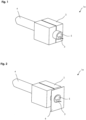
- FIG. 1 shows a schematic representation of a device 1a for connecting the joint of two profile ends of a body sealing element designed as an elongated sealing profile.
- the device 1a comprises a holding device 2 in which a first profile end 3 of a sealing profile 4 is held.
- the sealing profile 4 is a sealing strip as used in the vehicle sector, for example for sealing doors or windows.
- the sealing profile 4 has a hollow chamber 5 which extends over the entire length of the sealing profile 4.
- the holding device 2 is designed in several parts and surrounds the sealing profile 4.
- the holding device 2 has an inner contour which corresponds to the outer contour of the sealing profile 4, so that the large-area contact ensures a secure frictional holding of the sealing profile 4.
- the profile end 3 protrudes slightly from the holding device 2, but it can also be provided that the sealing profile 4 is in the holding device 2 is positioned so that it is flush with the holding device.
- Figure 2 is the arrangement of Figure 1 shown in a further process step.
- a template 6 is used which is designed in the form of a thin panel and has a recess corresponding to the cross section of the sealing profile.
- the template 6 is positioned in such a way that the profile end 3 is arranged in the recess and the front side of the profile end 3 is flush with the template 6. This reliably covers those sections of the sealing profile 4 to which no connecting agent is to be applied.
- Figure 3 shows the arrangement of Figure 2 in a subsequent process step.
- an application device (not shown here)
- a thin layer of a connecting agent 7 is applied to the front side of the profile end 3.
- the application device can be, for example, a spray nozzle for spraying on a liquid or powdered connecting agent or an application roller for applying a liquid connecting agent.
- the template 6 ensures that the connecting agent 7 is only applied to the front side of the profile end 3.
- Figure 4 shows the arrangement of Figure 3 in a further process step.
- the binding agent 7 is heated by means of a heating device (not shown) and a profile end 8 of a further sealing profile 9 is pressed against the first profile end 3.
- a heating device not shown
- the profile ends 3, 8 are firmly connected at the resulting joint 10.
- the second profile end of the sealing profile 4 can also be connected to the first profile end 3, so that an annular sealing profile 4 is produced.
- the cross-section of the further sealing profile 9 is identical to the cross-section of the sealing profile 4, in particular a corresponding hollow chamber 11 is also provided there. Due to the precise application of the connecting means 7 on the front side of the first profile end 3, there is no significant reduction in cross-section when the profile ends 3, 8 are connected, so that air and liquid can pass unhindered between the hollow chambers 5, 11 of the sealing profiles 4, 9 via the joint 10.
- FIG 5 is a perspective view of a first process step for connecting sealing profiles 4, 9, which, contrary to the Figures 1-4 shown design is attached directly to the body 12 of a vehicle.
- the sealing profiles 4, 9 can be the same profile of a body sealing element which was, for example, unrolled from a roll as an endless strand and attached to the body 12 until the ends 3, 8 are preferably opposite each other without a gap.
- the body sealing element can also be cut to length from the endless strand only after it has been unrolled and attached to the body 12, when the profile end to be connected is reached during unrolling.
- the sealing profiles 4, 9 can also be designed separately and only face each other at the profile ends 3, 8.
- the profile can be cut off at an angle of 90°, ie perpendicular to the longitudinal direction, as shown in the drawings, but also as an oblique cut at an angle deviating from 90°, such as 45°.
- FIG 6 is a perspective view of a second process step for connecting the sealing profiles 4, 9 of Figure 5 shown.
- the sealing profiles 4, 9 are pulled apart at the profile ends 3, 8 by means of a gripping device (not shown) in order to enlarge the gap between the profile ends 3, 8.
- the profile ends 3, 8 can optionally be heated in preparation for the application of the shapeless connecting means 7.
- Figure 7 is a perspective view of a third process step for connecting the sealing profiles 4, 9 to the body 12.
- an intermediate carrier 13 with a shapeless connecting means 7 detachably held thereon is moved into the gap between the profile ends 3, 8 and the shapeless connecting means 7 is positioned opposite at least one of the profile ends 3, 8 so that it can be applied to the at least one profile end 3, 8.
- the shapeless connecting means 7 is formed according to the cross-sectional shape of the sealing profiles 4, 9 on the profile ends 3, 8 and is applied to the intermediate carrier 13 by spraying or rolling.
- the shapeless connecting means 7 can, however, also be arranged in a different arrangement on the intermediate carrier 13, for example in a point-like manner and in particular distributed over the entire surface.
- the embodiment shown provides that the gripping device (not shown) moves the profile ends 3, 8 towards one another and thus presses against the shapeless connecting means 7 on the intermediate carrier 13, whereby the shapeless connecting means 7 is transferred to the profile ends 3, 8.
- the shapeless connecting means 7 can be applied to both sides of the intermediate carrier 13 opposite the profile ends 3, 8 in order to provide both profile ends 3, 8 with a shapeless connecting means 7 in one work step.
- the shapeless connecting means 7 can also be transferred from just one side of the intermediate carrier 13 to one of the profile ends 3, 8. As soon as the shapeless connecting means 7 has been transferred to the at least one profile end 3, 8, the intermediate carrier 13 is removed from the gap between the profile ends 3, 8.
- FIG 8 a perspective view of a fourth method step for connecting the sealing profiles 4, 9 to the body 12 is shown.
- the profile ends 3, 8 are pressed together by means of the gripping device (not shown) so that they are firmly bonded to the shapeless connecting means 7.
- the gripping device (not shown) can be removed from the sealing profiles 4, 9, thereby completing the connection process.
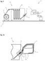
- FIG 9 is a schematic representation of a device 14 for mounting a body sealing profile on a vehicle body in the form of a vehicle door 15.
- the mounting device 14 is supported on a foundation 16 and comprises a robot 17 with a holding arm for precise movement and positioning of the vehicle door 15 and a feed device 18 for feeding a sealing profile 4 to the vehicle door 15.
- the feed device 18 comprises a supply winding 19 in which the sealing profile 4 is preferably wound as a so-called endless strand, the length of which corresponds to a multiple of the length of the cut body sealing element.
- the sealing profile 4 is guided to a holding device 21 via several movable deflection rollers 20, which form a buffer in particular when replacing an empty supply winding.
- the sealing profile 4 is held near its free end and can thus be positioned precisely opposite the vehicle door 15.
- the holding device 21 also enables the sealing profile 4 to be guided in order to enable the sealing profile 4 to be mounted on the vehicle door 15.
- FIG 10 a schematic representation of the assembly of the sealing profile 4 on the vehicle door 15 is shown.
- the vehicle door 15 is positioned by the robot 17 (not shown here) in relation to the static holding device 21 in such a way that the sealing profile 4 can be fastened to the vehicle door 15 along a closed sealing strip 22 using the holding device 21.
- the holding device 21 comprises a transport device 23, which in this embodiment comprises two conveyor belts between which the sealing profile 4 is clamped. At least one of the conveyor belts can be driven by a motor, so that the sealing profile 4 can be transported and fed very precisely.
- the holding device 21 comprises a pressure element 24 in the form of a pressure roller, by means of which the sealing profile 4 can be pressed along the sealing strip 22 on the vehicle door 15. Starting from the free profile end 3, the sealing profile 4 can thus be mounted on the closed sealing strip 22 by continuously feeding the sealing profile 4 and positioning the vehicle door 15 in such a way that the pressure element 24 is moved with the sealing profile 4 along the sealing strip 22 until the first profile end 3 is reached.
- the holding device 21 preferably also comprises a separating device for cutting/separating the sealing profile 4.
- the profile end 3 When the profile end 3 has been reached during the assembly of the sealing profile 4, the profile end 3 can preferably be precisely detected by machine using appropriate detection devices and the sealing profile 4 can be cut to length exactly in such a way that there is no or only a very small gap between the first profile end 3 and the second profile end resulting from the cutting. gap is present.
- a shapeless connecting means can then be applied to at least one of the profile ends by an application device (not shown here) which can be integrated into the holding device 21. After heating the shapeless connecting means by a heating device, preferably to a melting temperature, the profile ends can then be connected by the shapeless connecting means, resulting in an annular body sealing element.
- a positioning device can also be provided for the exact positioning of the profile ends relative to one another and, if necessary, for pulling the profile ends apart before and pressing the profile ends together after the application of the informal connecting means.
- the informal connecting means can also be applied, for example, using an intermediate carrier.
- the intermediate carrier For the design of the intermediate carrier, reference is made to the general description and the other embodiments described, which can be easily combined.
- the holding device 21 can also be designed to be movable and the vehicle door 15 can be held statically, so that the holding device 21 with the sealing profile 4 is moved along the sealing strip 22 on the vehicle door 15 in order to mount the sealing profile 4 on the vehicle door 15.
- This has the advantage that the profile end 3 is not moved together with the vehicle door 15 and therefore the shapeless connecting means can be applied to the profile end 3 by means of an application device, possibly even more easily during the assembly of the sealing profile 4.
- a body sealing element cut to length from a sealing profile in a preceding work step can also be attached to the vehicle door 15 by means of the holding device 21. If the body sealing element is cut to a precise length, the final cutting step on the vehicle door is omitted. If the body sealing element is cut to an excess length beforehand, this excess must be removed after installation on the vehicle door before the profile ends are connected.
- the assembly device 14 shown can not only be used to connect the ends of a body sealing element to one another, but it is also possible to attach a body sealing element to another body sealing element that may already be mounted and to connect both body sealing elements to one another using the method described. This is particularly advantageous if different profile cross-sections are required on the body in sections, so that the individual sections can be assembled from individual body sealing elements using the method without gaps and are firmly connected. In this way, it is also possible to attach one body sealing element to another laterally, i.e. between the ends, which is advantageous for window seals, for example.
Landscapes
- Engineering & Computer Science (AREA)
- Mechanical Engineering (AREA)
- Automobile Manufacture Line, Endless Track Vehicle, Trailer (AREA)
- Seal Device For Vehicle (AREA)
- Lining Or Joining Of Plastics Or The Like (AREA)
- Laminated Bodies (AREA)
- Mutual Connection Of Rods And Tubes (AREA)
Description
- Die Erfindung betrifft ein Verfahren zum Verbinden des Stoßes von zwei Enden mindestens eines Karosseriedichtungselements, insbesondere einer Kraftfahrzeug-Dichtung. Des Weiteren betrifft die Erfindung eine Vorrichtung zur Durchführung des Verfahrens.
- Entsprechende Karosseriedichtungselemente werden in Kraftfahrzeugen dazu verwendet, Bauteile, wie beispielsweise eine Tür und den entsprechenden Türrahmen, gegeneinander abzudichten. Das Karosseriedichtungselement dient dabei sowohl dem Schutz gegen Eindringen von Feuchtigkeit, Lärm oder Schmutz als auch der Wärmeisolierung. Um eine möglichst lückenlose Abdichtung zu gewährleisten, werden oftmals mehrere, teilweise unterschiedlich ausgebildete Karosseriedichtungselemente an den Enden stoffschlüssig miteinander verbunden, beispielsweise mittels Verkleben oder Verschweißen.
- Um eine Prozessautomatisierung eines entsprechenden Verbindungsverfahren zu ermöglichen, schlägt die
EP 1 915 270 B1 vor, bei einem an der Oberfläche eines Fahrzeugs angebrachten Karosseriedichtungselements in Form eines Dichtungsprofils die Profilenden voneinander im Abstand anzuordnen und in den entstehenden Spalt eine Schweißfolie einzubringen, die zuerst erhitzt und anschließend gegen die gegenüberliegenden Profilenden des Dichtungsprofils gedrückt wird, um diese zu verschweißen. Nach dem Verbinden der Profilenden können die vorstehenden Reste der Schweißfolie, sofern diese zugänglich sind, manuell entfernt werden. Weißt das Dichtungsprofil hingegen Hohlkammern auf, werden diese durch die Schweißfolie verschlossen und damit der Austausch von Luft oder das Abfließen von Flüssigkeit in den Hohlkammern über den Stoß hinweg verhindert. Aus derWO 01/89811 A1 - Aus
JP S52 24278 A DE 27 37 158 A1 ,EP 0 665 261 A2 ,JP H04 8781 A WO 2017/178017 A1 und insbesondere das PatentdokumentDE 39 06 278 A1 , das die Oberbegriffe der beigefügten unabhängigen Ansprüche offenlegt, sind verschiedene Verfahren zur Verklebung von Gummiprofilen bekannt. - Aufgabe der Erfindung ist es, ein Verfahren zum Verbinden des Stoßes von zwei Enden mindestens eines Karosseriedichtungselements zu schaffen, welches eine sichere und schnelle Verbindung der Enden und bei der Verwendung von Karosseriedichtungselementen mit einer oder mehreren Hohlkammern zusätzlich einen ungehinderten Durchtritt von Luft und Feuchtigkeit zwischen Hohlkammern innerhalb des Karosseriedichtungselements über den Stoß hinweg ermöglicht.
- Diese Aufgabe wird dadurch gelöst, dass gemäß dem Verfahren die Enden zuerst voneinander beabstandet angeordnet sind und auf mindestens ein Ende über einen Zwischenträger ein formloses Verbindungsmittel aufgebracht wird, wobei der Zwischenträger elektrostatisch aufgeladen wird, um das Verbindungsmittel zu halten. Anschließend wird das Verbindungsmittel erhitzt und die Enden zeitgleich oder nachfolgend in gegenseitigen Kontakt gebracht, wodurch die Enden am Stoß durch das erhitzte Verbindungsmittel stoffschlüssig verbunden werden. Das Erhitzen des Verbindungsmittels kann dabei vor dem gegenseitigen Kontakt der Enden am Stoß oder auch erst nach dem Kontakt erfolgen. Auf diese Art können sowohl die Enden von einem Karosseriedichtungselement miteinander verbunden werden, um eine ringförmige Dichtung zu bilden, wie auch die Enden mehrerer separater Karosseriedichtungselemente mit gleichem oder bei ausreichendem Überlappungsbereich an der Verbindungsstelle auch unterschiedlichem Querschnitt, um einen Übergang zu bilden.
- Bei den Karosseriedichtungselementen kann es sich um Dichtungsprofile, also üblicherweise mittels Extrusion hergestellten länglichen Dichtungen mit konstantem Querschnitt, oder um Formteile jeglicher Geometrie, beispielsweise im Spritzgussverfahren hergestellte Eckstücke, handeln. Zudem kann das Verbindungsmittel auf dem gesamten Ende des Karosseriedichtungselements oder nur auf einem Teilbereich der Kontaktfläche aufgebracht werden. Als Ende des Karosseriedichtungselements ist diejenige Kontaktfläche an einem Karosseriedichtungselement zu verstehen, an welche das weitere Ende desselben oder ein Ende eines weiteren Karosseriedichtungselements befestigt werden soll. Diese Kontaktfläche kann also überall an einem Karosseriedichtungselement vorgesehen sein und ist räumlich nicht auf einen vorgelagerten Endbereich beschränkt.
- Anstelle nur eines Endes kann das Verbindungsmittel auch auf beide gegenüberliegende Enden aufgebracht werden wodurch sich gegebenenfalls die Haltekraft erhöht. Zudem kann das Aufbringen des Verbindungsmittels und das Verbinden der Enden in derselben Maschine oder in unterschiedlichen Maschinen mit zeitlichem Abstand erfolgen. Beispielsweise ist es denkbar, dass bei Karosseriedichtungselementen in Form von länglichen Dichtungsprofilen beim Ablängen entsprechender Dichtungsprofile auf mindestens ein Profilende bereits ein Verbindungsmittel aufgebracht wird, die Dichtungsprofile jedoch zwischenzeitlich gelagert und in einem späteren Arbeitsschritt - gegebenenfalls auch erst direkt am Fahrzeug - durch Erhitzen des Verbindungsmittels miteinander verbunden werden.
- Bevorzugt kann als formloses Verbindungsmittel ein Schüttgut, insbesondere ein Pulver (besonders bevorzugt mit einer Korngröße kleiner 200 µm) oder Granulat, eine Flüssigkeit oder eine Paste verwendet werden. Hierdurch ist es möglich, das Verbindungsmittel exakt dosiert und damit effizient auf die Enden aufzubringen, so dass es zu keiner wesentlichen Reduzierung des Querschnitts der Hohlkammer am Stoß durch hervorstehendes Verbindungsmittel kommt. Zudem ist ein entsprechend formloses Verbindungsmittel universell bei jedem Profilquerschnitt bzw. jeder Kontaktfläche ohne weiteres aufbringbar.
- Als Zwischenträger kann beispielsweise eine Platte dienen, auf welche das formlose Verbindungsmittel entsprechend der Kontaktfläche des zu verbindenden Karosseriedichtungselements aufgebracht wird. Hierbei ist es zudem möglich, mehrere derartige Zwischenträger mit Verbindungsmittel in einem parallelen Arbeitsprozess vorzubereiten, um eine besonders hohe Taktrate beim Verbinden der Karosseriedichtungselemente zu erreichen. Das Auftragen des Verbindungsmittels kann dabei manuell, teilautomatisiert oder vollautomatisiert erfolgen.
- Das Verbindungsmittel kann durch Aufsprühen, Aufrollen oder punktweises Auftragen direkt auf das mindestens eine Ende und/oder den Zwischenträger aufgebracht werden. Die Haftung auf dem Ende oder dem Zwischenträger kann dabei mittels Adhäsion oder elektrostatische Ladung, wie dies bei Pulverlacken zur Metallbeschichtung bekannt ist, bewirkt werden. Das Aufsprühen kann bevorzugt in einer geschlossenen Kammer erfolgen, in welcher überschüssiges Verbindungsmittel abgesaugt und wiederverwendet wird. Der Zwischenträger und/oder das Ende kann zudem erhitzt werden, um ein Anhaften des Verbindungsmittels zu erleichtern. Ein besonders präziser Auftrag von Verbindungsmittel kann dabei mittels einer robotergeführten Spritz- oder Extrusionsdüse erreicht werden. Hierzu kann beispielsweise ein Führungsgestell vorgesehen sein, welches eine Bewegung der Düse parallel zu dem Stoß ermöglicht, so das mit der Düse das Verbindungsmittel ähnlich dem Schmelzschichtungsverfahren punktweise in Form einzelner Verbindungsmittelpunkte, linienförmig in Form einer Raupe oder auch flächig an dem mindestens einen Ende oder auf dem Zwischenträger aufbringbar ist.
- Zusätzlich kann das Verbindungsmittel und/oder das mindestens eine Ende bzw. der Zwischenträger elektrostatisch aufgeladen werden, um das Verbindungsmittel insbesondere punktweise festzuhalten. Der Zwischenträger kann dabei wie die Bildtrommel eines Laserdruckers lokal begrenzt elektrostatisch aufgeladen werden, so das nur dort entsprechend entgegengesetzt geladene Teilchen des Verbindungsmittels elektrostatisch haften. Um die Übertragung des Verbindungsmittels von dem Zwischenträger auf das mindestens eine Ende zu erleichtern, kann zudem vorgesehen sein, den Zwischenträger zu entladen, sobald das Verbindungsmittel mit dem Ende in Kontakt kommt. Hierdurch wird vorteilhaft ein Ablösen des Verbindungsmittels von dem Zwischenträger und ein Auftragen des Verbindungsmittels auf das mindestens eine Ende erleichtert.
- In einer alternativen Ausführungsform kann das Verbindungsmittel auch durch Kontaktieren des mindestens einen Endes mit einer Verbindungsmittelschicht oder mit einem Zwischenträger aufgebracht werden. Hierbei kann das Verbindungsmittel insbesondere mit einer definierten Schichtstärke in einem Behälter vorgesehen werden, so dass bei einem Kontaktieren des mindestens einen Endes mit der Verbindungsmittelschicht eine definierte Menge an Verbindungsmittel aufgebracht wird. Dies kann beispielsweise dadurch erreicht werden, dass vor jedem Kontaktieren ein Abstreifer mit definiertem Abstand zum Boden des Behälters überschüssiges Verbindungsmittel abstreift, sodass nur eine definierte Schichtstärke an Verbindungsmittel am Behälterboden verbleibt.
- Das Erhitzen des auf das mindestens eine Ende aufgebrachten Verbindungsmittels kann vorzugsweise mit Hilfe einer Heizeinrichtung, insbesondere einem IR-Heizelement, einem Heizluftgebläse oder einem Laser, erfolgen. Alternativ kann auch ein Mikrowellengenerator verwendet werden, um vorzugsweise in dem Verbindungsmittel vorgesehene Metallteilchen zu erhitzen. Durch die Heizeinrichtung wird das Verbindungsmittel bevorzugt aufgeschmolzen, also mindestens bis zu einer spezifischen Schmelztemperatur erhitzt, so dass das Verbindungsmittel (zähflüssig wird und besonders gut an den gegenüberliegenden Enden haftet. Anstelle der Heizeinrichtung kann jedoch auch die Restwärme des Karosseriedichtungselements aus einem vorgeschalteten Bearbeitungsschritt, beispielsweise dem Extrudieren des Karosseriedichtungselements als Dichtungsprofil, genutzt werden, um das Verbindungsmittel zu erhitzen. Sobald das Verbindungsmittel abgekühlt ist, bildet dieses eine stoffschlüssig Verbindung zwischen den Enden.
- Es kann zudem vorgesehen sein, dass der Zwischenträger und/oder das mindestens eine Ende vor der Aufbringung des Verbindungsmittels zusätzlich erhitzt werden, um die Haftung des Verbindungsmittels an dem Zwischenträger bzw. dem Ende zu erleichtern. Das Ende kann dabei in einem separaten Bearbeitungsschritt erhitzt werden oder eine Restwärme aus einem vorgeschalteten Bearbeitungsschritt, beispielsweise dem Extrudieren des Karosseriedichtungselements als Dichtungsprofil, aufweisen. Vorzugsweise wird dabei der Zwischenträger und/oder das mindestens eine Ende vor der Aufbringung des Verbindungsmittels auf eine Temperatur erhitzt, welche unterhalb der Schmelztemperatur des Verbindungsmittels liegt. Demnach wird das Verbindungsmittel beim Kontakt mit dem Zwischenträger oder dem mindestens einen Ende nicht aufgeschmolzen, sondern lediglich erweicht, wodurch sich die Haftung an dem Zwischenträger oder dem mindestens einen Ende erhöht. Das Erhitzen des Verbindungsmittels kann dabei direkt durch Wärmeeintrag in das Verbindungsmittel wie auch indirekt durch Erwärmung des Zwischenträgers oder des mindestens einen Endes erreicht werden. Vorteilhaft kann das Verbindungsmittel, der Zwischenträger und/oder das mindestens eine Ende vor Kontakt mit dem Verbindungsmittel auf eine Temperatur unterhalb der Schmelztemperatur, bevorzugt auf bis zu 200 °C, insbesondere bis zu 150 °C, erhitzt werden und zur Verbindung der Enden des mindestens einen Karosseriedichtungselements ist ein Erhitzen des Verbindungsmittels mindestens auf die Schmelztemperatur, insbesondere auf eine Temperatur von 120 °C bis 300 °C, vorteilhaft.
- Um einen präzisen Auftrag des Verbindungsmittels auf den Zwischenträger oder das mindestens eine Ende zu ermöglichen, kann vorgesehen sein, dass Abschnitte des Zwischenträgers oder des mindestens einen Karosseriedichtungselements, auf welche kein Verbindungsmittel aufgebracht werden soll, mittels einer Schablone abgedeckt werden. Die Schablone kann dabei derart verwendet werden, dass diese beim Erhitzen des Zwischenträgers, des mindestens einen Endes und/oder des Verbindungsmittels die übrigen Abschnitte des Zwischenträgers bzw. des Karosseriedichtungselements gegen die Wärmestrahlung abdeckt und/oder beim Auftrag des Verbindungsmittels beispielsweise mittels Aufsprühen oder Aufrollen ein Kontakt des Verbindungsmittels mit den übrigen Abschnitten des Zwischenträgers und/oder des Karosseriedichtungselements verhindert. Die Schablone kann dabei entsprechend präpariert sein, beispielsweise elektrostatisch geladen, gekühlt und/oder beschichtet sein, um ein Anhaften des Verbindungsmittels an der Schablone zu verhindern.
- Bevorzugt umfasst das Verbindungsmittel einen thermoplastischen und/oder duroplastischen Werkstoff, wobei der thermoplastische Werkstoff durch Erhitzen verflüssigbar ist und der duroplastische Werkstoff unter Hitzeeinwirkung und/oder aufgrund chemischer Reaktion aushärtet. Das Verbindungsmittel kann des Weiteren einstoffig oder als Stoffgemisch ausgebildet sein, beispielsweise als Paste (Suspension) mit einem hohen Gehalt an Festkörpern. Insbesondere zur Verbindung von Karosseriedichtungselementen aus unterschiedlichen Werkstoffen kann das Verbindungsmittel auch mehrschichtig aus mindestens zwei Komponenten bestehen, wobei eine erste Komponente eine besonders gute Haftwirkung mit dem Werkstoff des ersten Karosseriedichtungselements und die zweite Komponente eine besonders gute Haftwirkung mit dem Werkstoff des zweiten Karosseriedichtungselements bietet. Die beiden Komponenten des Verbindungsmittels können derart ausgewählt sein, dass diese zudem gut aneinander haften, alternativ kann zwischen den zwei Komponenten jedoch auch mindestens eine weitere Komponente vorgesehen sein, welche u.a. als Haftvermittler zwischen den beiden äußeren Komponenten wirkt. Die mindestens zwei Komponenten können dabei separat auf die zu verbindenden Enden aufgetragen werden und erst beim anschließenden Verbinden der Enden verbunden werden. Alternativ ist es jedoch auch möglich, die beiden Komponenten insbesondere schichtweise auf ein Ende des Karosseriedichtungselements aufzutragen, wobei die für den Werkstoff dieses Karosseriedichtungselements ausgelegte Komponente zuerst aufgetragen wird und anschließend, ggf. nach dem Auftrag einer oder mehrerer Zwischenschichten, die zweite Komponente aufgetragen wird, welche eine besonders gute Verbindung mit dem Werkstoff des weiteren Karosseriedichtungselement ermöglicht. Die zweite Komponente kommt dann mit dem weiteren Karosseriedichtungselement erst in Kontakt, wenn die beiden Enden der Karosseriedichtungselemente verbunden werden.
- Die Aufbringung des formlosen Verbindungsmittels kann vor der Befestigung des Karosseriedichtungselements an einer Karosserie eines Fahrzeugs oder während bzw. nach einer zumindest abschnittsweisen Befestigung des Karosseriedichtungselements an der Karosserie erfolgen.
- Erfolgt die Aufbringung des formlosen Verbindungsmittels vor der Befestigung des Karosseriedichtungselements an der Karosserie, können mit dem formlosen Verbindungsmittel versehene Karosseriedichtungselemente in einem separaten Schritt hergestellt werden. Dies ermöglicht die Vorbereitung bereits abgelängter und mit formlosem Verbindungsmittel versehener Karosseriedichtungselemente ggf. beim Hersteller der Karosseriedichtungselemente, so dass die Montage am Fahrzeug besonders schnell erfolgen kann. Hierbei können die Profilenden vor der Montage des Karosseriedichtungselements an der Karosserie oder auch während bzw. nach der Montage des Karosseriedichtungselements an der Karosserie durch das Verbindungsmittel verbunden werden.
- Bei der Aufbringung des formlosen Verbindungsmittels während oder nach der zumindest abschnittsweisen Befestigung des Karosseriedichtungselements an der Karosserie können mehrere Arbeitsschritte simultan ausgeführt werden, was besondere kurze Produktionszeiten zur Folge hat. So kann beispielsweise das formlose Verbindungsmittel auf ein an der Karosserie bereits befestigtes erstes Ende des Karosseriedichtungselements aufgebracht werden, während der übrige Abschnitt des Karosseriedichtungselements noch an der Karosserie befestigt wird.
- Das Karosseriedichtungselement kann vor einer Befestigung an einer Karosserie eines Fahrzeugs passgenau auf die notwendige Länge oder mit Übermaß abgelängt und bevorratet werden. Beim Ablängen mit Übermaß wird das Karosseriedichtungselement üblicherweise um eine geringe Überlänge von z.B. 1 - 500 mm länger abgelängt, um Toleranzen auszugleichen. Das Ablängen kann dabei bevorzugt erst im Zuge des Montageprozesses des Dichtungselements an der Fahrzeugtür erfolgen, insbesondere nach der zumindest teilweisen bzw. vollständigen Befestigung des Karosseriedichtungselements an der Karosserie des Fahrzeugs, so dass das Ablängen besonders präzise erfolgt und ein Spalt zwischen den Enden vermieden wird.
- Alternativ kann auch vorgesehen sein, dass das Karosseriedichtungselement von einer Vorratswicklung entnommen und erst nach einer zumindest abschnittsweisen Befestigung an einer Karosserie eines Fahrzeugs abgelängt wird. Eine derartige Vorratswicklung wird auch als Endlosdichtung bezeichnet und umfasst eine Profildichtung, welche ein Vielfaches der Länge eines einzelnen an der Karosserie anzubringenden Karosseriedichtungselements aufweist, wobei die einzelnen Karosseriedichtungselemente durch Abtrennen von der Vorratswicklung in der gewünschten Länge erzeugt werden. Eine Vorratswicklung hat den Vorteil, dass hieraus eine große Anzahl an einzelnen Karosseriedichtungselementen hergestellt werden können und die Vorratswicklung besonders platzsparend gelagert und einfach zum Hersteller der Fahrzeuge geliefert werden kann. Bei der vorteilhaften Verarbeitung einer Vorratswicklung bzw. Endlosdichtung erfolgt das Ablängen des Karosseriedichtungselements abhängig vom jeweiligen Fahrzeugtyp und damit sehr individuell erst unmittelbar im Produktionsprozess des Fahrzeughersteller, so dass beim Fahrzeughersteller nicht verschiedene Längen von Karosseriedichtungselementen bevorratet werden müssen. Heutige Türdichtungen eines PKWs weisen üblicherweise eine Länge von ca. 3,5 m auf, die Anlieferform einer heute üblichen Vorratswicklung bzw. Endlosdichtung liegt bei teilweise mehr als der 100-fachen Länge eines einzelnen Karosseriedichtungselements.
- Das formlose Verbindungsmittel kann vor dem Ablängen auf ein Ende des Karosseriedichtungselements aufgebracht werden, beispielsweise auf das freie Ende des auf der Vorratswicklung befindlichen Dichtungsstrangs. Das Karosseriedichtungselement kann dann direkt von der Vorratswicklung ggf. maschinell an der Karosserie montiert und anschließend abgelängt werden. Vor der Verbindung der beiden Enden kann dann ggf. zusätzlich noch ein formloses Verbindungsmittel auf das zweite Ende aufgebracht werden. Alternativ kann jedoch die Aufbringung des formlosen Verbindungsmittels auf mindestens eines der Enden erst nach dem Ablängen des Karosseriedichtungselements erfolgen. Wird das Karosseriedichtungselement direkt passgenau auf die notwendige Länge abgelängt/ gekürzt, kann auf einem oder beiden Enden das formlose Verbindungsmittel aufgebracht werden. Wird das Karosseriedichtungselement zuerst mit Übermaß abgelängt, kann das formlose Verbindungsmittel bereits auf das eine Ende und nach dem passgenauen Ablängen ggf. auch auf das weitere Ende aufgebracht werden. Alternativ kann das formlose Verbindungsmittel auf das eine oder beide Enden aufgebracht werden, nachdem das Karosseriedichtungselement von dem Übermaß auf die passgenaue Länge abgelängt wurde. In jedem Fall hat es sich als besonders vorteilhaft herausgestellt, das formlose Verbindungsmittel kurze Zeit nach dem Ablängen/Schneiden des Karosseriedichtungselements auf das entsprechende Ende aufzubringen, da das formloses Verbindungsmittel dann besonders gut haftet.
- In einer besonders vorteilhaften Ausführungsform kann in einer ggf. maschinellen Montage des Karosseriedichtungselements an der Fahrzeugtür bzw. Karosserie die Verbindung der beiden Profilenden des Karosseriedichtungselements in den Montageprozess des Automobilherstellers integriert werden. Bei der Variante bei welcher das Karosseriedichtungselement von einer Vorratswicklung verarbeitet wird, kann das formlose Verbindungsmittel folglich während drei unterschiedlicher Prozessschritte auf das je nach Prozessschritt eine freie Profilende oder beide Profilenden des Karosseriedichtungselements aufgetragen werden (siehe folgende Varianten A-C).
- A) Vor dem Start der Montage eines noch nicht abgelängten Karosseriedichtungselements an der Karosserie eines Fahrzeugs kann auf das zu diesem Zeitpunkt schon einseitig frei zugängliche Profilende des Karosseriedichtungselements ein formloses Verbindungsmittel aufgetragen werden.
- B) Während der Montage des zumindest schon abschnittsweise befestigten, aber noch nicht abgelängten Dichtungselements kann ein formloses Verbindungsmittel auf das zu diesem Zeitpunkt einseitig frei zugängliche Profilende des Karosseriedichtungselements aufgetragen werden.
- C) Nach der Montage und dem Ablängen des Karosseriedichtungselements kann ein formloses Verbindungsmittel auf eines oder beide der zu diesem Zeitpunkt dann frei zugänglichen Profilenden des Karosseriedichtungselements aufgetragen werden.
- Die Varianten A-C sind auch kombinierbar, so dass beispielsweise vor dem Start der Montage des Karosseriedichtungselements an der Karosserie auf das eine bereits zugängliche Profilende des Dichtungselements das formlose Verbindungsmittel aufgebracht wird (Variante A) und nach der Montage und dem Ablängen des Dichtungselements das formlose Verbindungsmittel zusätzlich auf das dann zugängliche weitere Profilende aufgebracht wird.
- Sollte nach der Montage des Dichtungselements an der Fahrzeugtür ein geringer Spalt zwischen den freien Enden des Dichtungselements vorhanden sein, so kann dieser durch ein Zusammendrücken der Enden beim Verbinden durch das Verbindungsmittel dauerhaft geschlossen werden.
- Bei der Variante des Ablängens des Karosseriedichtungselements von einer Vorratswicklung bzw. einem Endlosstrang und somit einem Auftrag des Verbindungsmittels erst im Produktionswerk des Fahrzeugherstellers besteht die Möglichkeit, unmittelbar vor dem Aufbringen des Karosseriedichtungselements an der Fahrzeugtür auf das zu diesem Zeitpunkt bereits einseitig vorliegende freie Profilende vor dem Start der Montage des Karosseriedichtungselements das formlose Verbindungsmittel aufzutragen und erst anschließend mit dem Montageprozess der Dichtung zu beginnen. Zudem kann beim anschließenden Verbindungsverfahren eine zur Aufbringung des Verbindungsmittels evtl. eingebrachte Prozesswärme direkt beim nachfolgenden Verbinden der Profilenden weiter genutzt werden.
- Wird das formlose Verbindungsmittel erst dann aufgebracht, wenn das mindestens eine Karosseriedichtungselement an der Karosserie eines Fahrzeugs, beispielsweise einer Fahrzeugtür, zumindest abschnittsweise befestigt ist, hat dies den Vorteil, dass die Aufbringung des Verbindungsmittels und die Verbindung der Profilenden zeitlich kurz nacheinander und direkt am Fahrzeug umgesetzt werden können, so dass eine besonders rationale Fertigung ermöglicht wird. Beispielsweise kann das Ablängen abhängig vom jeweiligen Fahrzeugtyp und damit sehr individuell gestaltet werden, so dass nicht verschiedene Längen von Karosseriedichtungselementen bevorratet werden müssen und die Karosseriedichtungselemente in Form einer Vorratswicklung bzw. eines Endlosstrangs, welcher ein Vielfaches der Länge eines einzelnen an der Karosserie anzubringenden Karosseriedichtungselements aufweist, zum Hersteller der Fahrzeuge geliefert werden können. Die Montage des Karosseriedichtungselements an der Karosserie erfolgt dabei z.B. durch Abrollen des Dichtprofils von der Vorratswicklung bzw. dem Endlosstrang und Befestigung direkt an der Karosserie, wobei das Karosseriedichtungselement vorteilhaft erst dann abgelängt wird, wenn das zu verbindende Profilende erreicht ist, so dass kein oder nur ein geringer Spalt zwischen den Profilenden vorhanden ist. Zudem kann beim anschließenden Verbindungsverfahren eine zur Aufbringung des Verbindungsmittels evtl. eingebrachte Prozesswärme direkt beim nachfolgenden Verbinden der Profilenden weiter genutzt werden.
- Des Weiteren wird eine Vorrichtung zur Durchführung des beschriebenen Verfahrens beansprucht, welche eine Halteeinrichtung zur positionsgenauen Halterung des mindestens einen Endes, eine Auftragseinrichtung mit einem elektrostatisch aufladbaren Zwischenträger zum Auftrag eines formlosen Verbindungsmittels auf das mindestens eine Ende, eine Heizeinrichtung zum Erhitzen des auf das mindestens eine Profilende aufgebrachten Verbindungsmittels und eine Positioniereinrichtung zum gegenseitigen Andrücken der Profilenden umfasst.
- Eine besonders schnelle und positionsgenaue Aufbringung des Verbindungsmittels kann dadurch erreicht werden, dass die Auftragseinrichtung als Spritz- oder Extrusionsdüse oder als Auftragsrolle ausgebildet ist. Alternativ kann die Auftragseinrichtung auch einen Verbindungsmittel-Behälter insbesondere mit einem seitlich verfahrbaren Abstreifer umfassen, welcher eine definierte Höhe über dem Behälterboden aufweist und damit das Verbindungsmittel im Behälterboden bis zu einer bestimmten gleichmäßigen Höhe abgestreift werden kann.
- Vorteilhaft kann die Heizeinrichtung als IR-Heizelement, Heißluftgebläse, Mikrowellengenerator oder Laser ausgebildet sein, womit sich das mindestens eine Profilende schnell und räumlich begrenzt erhitzen lässt.
- Um das Verbindungsmittel besonders positionsgenau aufzutragen, kann die Vorrichtung eine Schablone zum Abdecken derjenigen Abschnitte des Dichtungsprofils umfassen, auf welche kein Verbindungsmittel aufgebracht werden soll.
- Weitere Besonderheiten und Vorzüge der Erfindung ergeben sich aus der folgenden Beschreibung eines bevorzugten Ausführungsbeispiels anhand der Zeichnungen. Es zeigen:
- Fig. 1
- eine perspektivische Darstellung einer Vorrichtung zur Verbindung von Dichtungsprofilen mit einem in einer Halteeinrichtung gehaltenen Profilende eines Dichtungsprofils,
- Fig. 2
- die Anordnung von
Figur 1 mit einer Schablone zum Abdecken bestimmter Abschnitte des Dichtungsprofils, - Fig. 3
- die Anordnung von
Figur 2 mit einem auf das Profilende aufgebrachten Verbindungsmittel, - Fig. 4
- die Anordnung von
Figur 3 mit einem durch das Verbindungsmittel mit dem Profilende verbundenen weiteren Profilende, - Fig. 5
- eine perspektivische Darstellung eines ersten Verfahrensschritts zur Verbindung von Dichtungsprofilen an einer Fahrzeugkarosserie,
- Fig. 6
- eine perspektivische Darstellung eines zweiten Verfahrensschritts zur Verbindung von Dichtungsprofilen an einer Fahrzeugkarosserie,
- Fig. 7
- eine perspektivische Darstellung eines dritten Verfahrensschritts zur Verbindung von Dichtungsprofilen an einer Fahrzeugkarosserie,
- Fig. 8
- eine perspektivische Darstellung eines vierten Verfahrensschritts zur Verbindung von Dichtungsprofilen an einer Fahrzeugkarosserie,
- Fig. 9
- eine schematische Darstellung einer Vorrichtung zur Montage eines Dichtungsprofils an einer Fahrzeugtür, und
- Fig. 10
- eine schematische Darstellung der Montage des Dichtungsprofils an der Fahrzeugtür von
Figur 9 . -
Figur 1 zeigt eine schematische Darstellung einer Vorrichtung 1a zur Verbindung des Stoßes von zwei Profilenden eines als längliches Dichtungsprofil ausgebildeten Karosseriedichtungselements. Die Vorrichtung 1a umfasst eine Halteeinrichtung 2 in welcher ein erstes Profilende 3 eines Dichtungsprofils 4 gehalten wird. Bei dem Dichtungsprofil 4 handelt es sich um einen Dichtungsstrang wie er im Fahrzeugbereich beispielsweise zur Abdichtung von Türen oder Fenstern verwendet wird. Das Dichtungsprofil 4 weist eine Hohlkammer 5 auf, welche sich über die gesamte Länge des Dichtungsprofils 4 erstreckt. Um das Dichtungsprofil 4 sicher zu halten, ist die Halteeinrichtung 2 mehrteilig ausgebildet und umgreift das Dichtungsprofil 4. Die Halteeinrichtung 2 weist hierzu eine Innenkontur auf, welche der Außenkontur des Dichtungsprofils 4 entspricht, so dass durch die großflächige Anlage eine sichere reibschlüssige Halterung des Dichtungsprofils 4 gewährleistet wird. - Das Profilende 3 steht geringfügig gegenüber der Halteinrichtung 2 vor, es kann jedoch auch vorgesehen sein, dass das Dichtungsprofil 4 derart in der Halteeinrichtung 2 positioniert wird, dass dieses bündig mit der Halteinrichtung abschließt.
- In
Figur 2 ist die Anordnung vonFigur 1 in einem weiteren Prozessschritt gezeigt. Um den Auftrag eines Verbindungsmittels vorzubereiten und sicherzustellen, dass das Verbindungsmittel nur an der Stirnseite des Profilendes 3 aufgebracht wird, wird eine Schablone 6 verwendet, welche in Form einer dünnen Tafel ausgebildet ist und eine Aussparung entsprechend dem Querschnitt des Dichtungsprofils aufweist. Die Schablone 6 wird derart positioniert, dass das Profilende 3 in der Aussparung angeordnet ist und die Stirnseite des Profilendes 3 bündig mit der Schablone 6 abschließt. Hierdurch werden diejenigen Abschnitte des Dichtungsprofils 4, auf welche kein Verbindungsmittel aufgebracht werden soll, zuverlässig abgedeckt. -
Figur 3 zeigt die Anordnung vonFigur 2 in einem nachfolgenden Prozessschritt. Mittels einer hier nicht dargestellten Auftragseinrichtung wird auf das Profilende 3 an der Stirnseite ein Verbindungsmittel 7 dünnflächig aufgebracht. Bei der Auftragseinrichtung kann es sich beispielsweise um eine Spritzdüse zum Aufspritzen eines flüssigen oder pulverförmigen Verbindungsmittels oder um eine Auftragsrolle zum Auftragen eines flüssigen Verbindungsmittels handeln. Durch die Schablone 6 wird dabei gewährleistet, dass das Verbindungsmittel 7 lediglich auf die Stirnseite des Profilendes 3 aufgetragen wird. -
Figur 4 zeigt die Anordnung vonFigur 3 in einem weiteren Prozessschritt. Mittels einer nicht dargestellten Heizeinrichtung wird das Bindemittel 7 erhitzt und ein Profilende 8 eines weiteren Dichtungsprofils 9 gegen das erste Profilende 3 gedrückt. Hierdurch werden die Profilenden 3, 8 an dem sich ergebenden Stoß 10 stoffschlüssig verbunden. Anstelle des Profilendes 8 eines weiteren Dichtungsprofils 9 kann auch das zweite Profilende des Dichtungsprofils 4 mit dem ersten Profilende 3 verbunden werden, so dass sich ein ringförmiges Dichtungsprofil 4 ergibt. - Der Querschnitt des weiteren Dichtungsprofils 9 ist identisch zum Querschnitt des Dichtungsprofils 4 ausgebildet, insbesondere ist dort auch eine entsprechende Hohlkammer 11 vorgesehen. Durch den präzisen Auftrag des Verbindungsmittels 7 auf der Stirnseite des ersten Profilendes 3 kommt es bei der Verbindung der Profilenden 3, 8 zu keiner wesentlichen Querschnittsreduzierung, so dass Luft und Flüssigkeit zwischen den Hohlkammern 5, 11 der Dichtungsprofile 4, 9 ungehindert über den Stoß 10 hindurchtreten kann.
- In
Figur 5 ist eine perspektivische Darstellung eines ersten Verfahrensschritts zur Verbindung von Dichtungsprofilen 4, 9 gezeigt, welche entgegen der in denFiguren 1-4 gezeigten Ausgestaltung direkt an der Karosserie 12 eines Fahrzeugs befestigt ist. Bei den Dichtungsprofilen 4, 9 kann es sich um das selbe Profil eines Karosseriedichtungselements handeln, welches beispielsweise von einer Rolle als endloser Strang abgerollt und an der Karosserie 12 befestigt wurde, bis sich die Enden 3, 8 vorzugsweise spaltfrei gegenüberliegenden. Für ein möglichst geringes Spaltmaß kann zudem das Ablängen des Karosseriedichtungselements von dem Endlosstrang erst nach dem Abrollen und Befestigen an der Karosserie 12 erfolgen, wenn das zu verbindende Profilende beim Abrollen erreicht ist. Alternativ können die Dichtungsprofile 4, 9 auch separat ausgebildet sein und sich lediglich an den Profilenden 3, 8 gegenüberstehen. Die Abtrennung des Profils kann wie in den Zeichnungen gezeigt unter einen Winkel von 90°, d.h. senkrecht zur Längsrichtung, aber auch als Schrägschnitt unter einem von 90° abweichenden Winkel wie z.B. 45° erfolgen. - In
Figur 6 ist eine perspektivische Darstellung eines zweiten Verfahrensschritts zur Verbindung der Dichtungsprofile 4, 9 vonFigur 5 gezeigt. Ausgehend von der inFigur 5 dargestellten Anordnung werden hierbei die Dichtungsprofile 4, 9 an den Profilenden 3, 8 mittels einer nicht dargestellten Greifeinrichtung auseinandergezogen, um den Spalt zwischen den Profilenden 3, 8 zu vergrößern. In diesem Verfahrensschritt kann gegebenenfalls ein Erhitzen der Profilenden 3, 8 als Vorbereitung für die Aufbringung des formlosen Verbindungsmittels 7 erfolgen. - In
Figur 7 ist eine perspektivische Darstellung eines dritten Verfahrensschritts zur Verbindung der Dichtungsprofile 4, 9 an der Karosserie 12 gezeigt. Ausgehend von dem inFigur 6 gezeigten Verfahrensschritt wird hierbei ein Zwischenträger 13 mit einem daran lösbar gehaltenen formlosen Verbindungsmittel 7 in den Spalt zwischen den Profilenden 3, 8 bewegt und das formlose Verbindungsmittel 7 gegenüber mindestens einem der Profilenden 3, 8 positioniert, so dass dieses auf das mindestens eine Profilende 3, 8 aufbringbar ist. Bei dem hier gezeigten Ausführungsbeispiel ist das formlose Verbindungsmittel 7 gemäß der Querschnittsform der Dichtungsprofile 4, 9 an den Profilenden 3, 8 ausgebildet und mittels Aufsprühen oder Aufrollen auf den Zwischenträger 13 aufgebracht. Das formlose Verbindungsmittel 7 kann jedoch auch in anderer Anordnung, beispielsweise punktförmig und insbesondere über die gesamte Fläche verteilt, auf dem Zwischenträger 13 angeordnet sein. Bezüglich der verschiedenen Aufbringungsmöglichkeiten auf den Zwischenträger, der unterschiedlichen Möglichkeiten der Haftung des formlosen Verbindungsmittel 7 an dem Zwischenträger 13, beispielsweise mittels elektrostatische Aufladung, sowie der Möglichkeiten für die Übertragung des formlosen Verbindungsmittels 7 auf die Profilenden 3, 8 wird auf obige allgemeine Ausführungen verwiesen. - Zur Übertragung des formlosen Verbindungsmittels 7 auf das mindestens eine Profilende 3, 8 ist bei der gezeigten Ausführungsform vorgesehen, dass die nicht dargestellten Greifeinrichtung die Profilenden 3, 8 zueinander bewegt und damit gegen das formlosen Verbindungsmittel 7 auf dem Zwischenträger 13 drückt, wodurch das formlosen Verbindungsmittel 7 auf die Profilenden 3, 8 übertragen wird. Das formlose Verbindungsmittel 7 kann dabei auf beiden, den Profilenden 3, 8 gegenüberliegenden Seiten des Zwischenträger 13 aufgebracht sein, um beide Profilenden 3, 8 in einem Arbeitsschritt mit einem formlosen Verbindungsmittel 7 zu versehen. Alternativ kann das formlose Verbindungsmittel 7 auch nur von einer Seite des Zwischenträger 13 auf eines der Profilenden 3, 8 übertragen werden. Sobald das formlose Verbindungsmittel 7 auf das mindestens eine Profilende 3, 8 übertragen wurde, wird der Zwischenträger 13 aus dem Spalt zwischen den Profilenden 3, 8 entfernt.
- In
Figur 8 ist eine perspektivische Darstellung eines vierten Verfahrensschritts zur Verbindung der Dichtungsprofile 4, 9 an der Karosserie 12 gezeigt. In diesem Verfahrensschritt werden die Profilenden 3, 8 mittels der nicht dargestellten Greifeinrichtung zusammengedrückt, so dass sich diese mit dem formlosen Verbindungsmittel 7 stoffschlüssig verbinden. Sobald das formlose Verbindungsmittel 7 ausreichend abgekühlt ist, kann die nicht dargestellte Greifeinrichtung von den Dichtungsprofilen 4, 9 entfernt werden, wodurch das Verbindungsverfahren abgeschlossen wird. - In
Figur 9 ist eine schematische Darstellung einer Vorrichtung 14 zur Montage eines Karosseriedichtungsprofils an einer Fahrzeugkarosserie in Form einer Fahrzeugtür 15 gezeigt. Die Montagevorrichtung 14 ist auf einem Fundament 16 abgestützt und umfasst einen Roboter 17 mit einem Haltearm für ein präzises Bewegen und Positionieren der Fahrzeugtür 15 sowie eine Zuführeinrichtung 18 zur Zuführung eines Dichtungsprofils 4 zu der Fahrzeugtür 15. Die Zuführungsvorrichtung 18 umfasst hierzu eine Vorratswicklung 19, in welcher das Dichtungsprofil 4 bevorzugt als sogenannter Endlosstrang aufgewickelt ist, dessen Länge einem Vielfachen der Länge des abgelängten Karosseriedichtungselements entspricht. - Von der Vorratswicklung 19 wird das Dichtungsprofil 4 über mehrere verschiebbare Umlenkrollen 20, welche einen Puffer insbesondere beim Austausch einer leeren Vorratswicklung bilden, zu einer Halteeinrichtung 21 geführt. In der Halteeinrichtung 21 wird das Dichtungsprofils 4 nahe seines freien Endes gehalten und kann so präzise gegenüber der Fahrzeugtür 15 positioniert werden. Die Halteeinrichtung 21 ermöglicht zudem das Nachführen des Dichtungsprofils 4, um eine Montage des Dichtungsprofils 4 an der Fahrzeugtür 15 zu ermöglichen.
- In
Figur 10 ist eine schematische Darstellung der Montage des Dichtungsprofils 4 an der Fahrzeugtür 15 gezeigt. Wie dort zu entnehmen ist, wird die Fahrzeugtür 15 durch den hier nicht dargestellten Roboter 17 zur statischen Halteeinrichtung 21 derart positioniert, dass mit der Halteeinrichtung 21 das Dichtungsprofil 4 entlang einer geschlossenen Dichtungsbahn 22 an der Fahrzeugtür 15 befestigt werden kann. - Um das Dichtungsprofil 4 von der Vorratswicklung 19 abzurollen, umfasst die Halteeinrichtung 21 eine Transporteinrichtung 23, welche bei diesem Ausführungsbeispiel zwei Förderbänder umfasst, zwischen welchen das Dichtungsprofil 4 eingespannt ist. Mindestens eines der Förderbänder ist motorisch antreibbar, so dass das Dichtungsprofil 4 sehr präzise transportiert und zugeführt werden kann.
- Zudem umfasst die Halteeinrichtung 21 ein Andruckelement 24 in Form einer Andruckrolle, mittels derer das Dichtungsprofil 4 entlang der Dichtungsbahn 22 an der Fahrzeugtür 15 andrückbar ist. Ausgehend von dem freien Profilende 3 kann somit durch kontinuierliches Nachfördern des Dichtungsprofils 4 und Positionieren der Fahrzeugtür 15 derart, dass das Andruckelement 24 mit dem Dichtungsprofil 4 entlang der Dichtungsbahn 22 bewegt wird, das Dichtungsprofil 4 auf der geschlossenen Dichtungsbahn 22 montiert werden bis das erste Profilende 3 erreicht ist. Zum Ablängen des Dichtungsprofils 4 umfasst die Halteeinrichtung 21 bevorzugt auch eine Trenneinrichtung zum Ablängen/Trennen des Dichtungsprofils 4.
- Wenn bei der Montage des Dichtungsprofils 4 das Profilende 3 erreicht wurde, kann bevorzugt mittels entsprechender Detektionseinrichtungen das Profilende 3 präzise maschinell erfasst werden und das Dichtungsprofil 4 exakt derart abgelängt werden, dass zwischen dem ersten Profilende 3 und dem sich durch das Ablängen ergebenden zweiten Profilende kein oder nur ein sehr geringer Spalt vorhanden ist. Anschließend kann durch eine hier nicht dargestellte Auftragseinrichtung, welche in die Halteeinrichtung 21 integriert sein kann, ein formloses Verbindungsmittel auf mindestens eines der Profilenden aufgebracht werden. Nach einem Erhitzen des formlosen Verbindungsmittels durch eine Heizeinrichtung bevorzugt auf eine Schmelztemperatur können die Profilenden anschließend durch das formlose Verbindungsmittel verbunden werden, wodurch sich ein ringförmiges Karosseriedichtungselement ergibt.
- Zur exakten Positionierung der Profilenden zueinander und gegebenenfalls zum Auseinanderziehen der Profilenden vor und Zusammendrücken der Profilenden nach der Aufbringung des formlosen Verbindungsmittels kann zudem eine Positioniereinrichtung vorgesehen sein. Wie bereits allgemein beschrieben, kann das formlose Verbindungsmittel zudem beispielsweise mittels eines Zwischenträgers aufgebracht werden. Zur Ausgestaltung des Zwischenträgers wird auf die allgemeine Beschreibung und die beschriebenen weiteren Ausführungsbeispiele verwiesen, welche ohne weiteres kombinierbar sind.
- In einer alternativen Ausführungsform kann auch die Halteeinrichtung 21 beweglich ausgebildet sein und die Fahrzeugtür 15 statisch gehalten werden, so dass die Halteeinrichtung 21 mit dem Dichtungsprofil 4 entlang der Dichtungsbahn 22 an der Fahrzeugtür 15 bewegt wird, um das Dichtungsprofil 4 an der Fahrzeugtür 15 zu montieren. Dies hat den Vorteil, dass das Profilende 3 zusammen mit der Fahrzeugtür 15 nicht bewegt wird und daher das formlose Verbindungsmittel mittels einer Auftragseinrichtung auf das Profilende 3 ggf. noch einfacher während der Montage des Dichtungsprofils 4 aufgetragen werden kann. Weiter alternativ kann anstelle des Dichtungsprofils 4, welches als sogenannter Endlosstrang in der Vorratswicklung 19 bevorratet ist und eine vielfache Länge gegenüber der Länge des benötigten Karosseriedichtungselements aufweist, auch ein in einem vorgeschalteten Arbeitsschritt von einem Dichtungsprofil abgelängtes Karosseriedichtungselement mittels der Halteeinrichtung 21 an der Fahrzeugtür 15 befestigt werden. Hierbei entfällt bei einem passgenau abgelängten Karosseriedichtungselement der Prozessschritt des abschließenden Ablängens an der Fahrzeugtür. Wird das Karosseriedichtungselement vorab mit einem Übermaß abgelängt, ist dieses Übermaß nach der Montage an der Fahrzeugtür vor der Verbindung der Profilenden zu entfernen. Auf die weiteren anwendbaren alternativen Verfahren wird auf die allgemeine Beschreibung sowie die Beschreibung zu den vorangehenden Figuren verwiesen, welche ohne weiteres kombinierbar sind.
- Mit der gezeigten Montagevorrichtung 14 können jedoch nicht nur die Enden eines Karosseriedichtungselements miteinander verbunden werden, sondern es ist ebenso möglich, ein Karosseriedichtungselement an ein ggf. bereits montiertes weiteres Karosseriedichtungselement anzusetzen und beide Karosseriedichtungselemente mittels dem beschriebenen Verfahren miteinander zu verbinden. Dies ist insbesondere vorteilhaft, wenn an der Karosserie abschnittsweise unterschiedliche Profilquerschnitte benötigt werden, so dass die einzelnen Abschnitte mittels dem Verfahren aus einzelnen Karosseriedichtungselementen spaltfrei zusammengesetzt werden können und fest verbunden sind. Auf diese Art ist es auch möglich, ein Karosseriedichtungselement an ein weiteres seitlich, also zwischen den Enden anzubringen, was beispielsweise bei Fensterdichtungen vorteilhaft ist.
-
- 1a, 1b
- Vorrichtung zur Verbindung des Stoßes von zwei Profilenden
- 2
- Halteeinrichtung
- 3
- Erstes Profilende
- 4
- Dichtungsprofil
- 5
- Hohlkammer
- 6
- Schablone
- 7
- Verbindungsmittel
- 8
- Zweites Profilende
- 9
- Weiteres Dichtungsprofil
- 10
- Stoß
- 11
- Hohlkammer
- 12
- Karosserie
- 13
- Zwischenträger
- 14
- Montagevorrichtung
- 15
- Fahrzeugtür
- 16
- Fundament
- 17
- Roboter
- 18
- Zuführeinrichtung
- 19
- Vorratswicklung
- 20
- Umlenkrollen
- 21
- Halteeinrichtung
- 22
- Dichtungsbahn
- 23
- Transporteinrichtung
- 24
- Andruckelement
Claims (14)
- Verfahren zum Verbinden des Stoßes (10) von zwei Enden (3; 8) mindestens eines Karosseriedichtungselements (4; 9), wobei die Enden (3; 8) zunächst voneinander beabstandet angeordnet sind und auf mindestens ein Ende (3) ein Verbindungsmittel (7) aufgebracht wird, wobei, anschließend das Verbindungsmittel (7) erhitzt wird und die Enden (3; 8) zeitgleich oder nachfolgend in gegenseitigen Kontakt gebracht werden, wodurch die Enden (3; 8) am Stoß (10) durch das erhitzte Verbindungsmittel (7) stoffschlüssig verbunden werden,
dadurch gekennzeichnet,
dass das Verbindungsmittel (7) formlos ist und über einen Zwischenträger (13), welcher elektrostatisch aufgeladen wird, um das Verbindungsmittel (7) zu halten, auf das mindestens eine Ende (3) aufgebracht wird. - Verfahren nach Anspruch 1,
dadurch gekennzeichnet,
dass als formloses Verbindungsmittel (7) ein Schüttgut, insbesondere Pulver oder Granulat, eine Flüssigkeit oder eine Paste, verwendet wird. - Verfahren nach Anspruch 1 oder 2,
dadurch gekennzeichnet,
dass das Verbindungsmittel (7) durch Aufsprühen, Aufrollen oder punktweises Auftragen direkt auf das mindestens eine Ende (3) und/oder den Zwischenträger (13) aufgebracht wird. - Verfahren nach einem der Ansprüche 1 bis 3,
dadurch gekennzeichnet,
dass das Verbindungsmittel (7) mittels einer robotergeführten Düse aufgebracht wird, insbesondere punktweise. - Verfahren einem der Ansprüche 1 bis 4,
dadurch gekennzeichnet,
dass der Zwischenträger (13) punktweise elektrostatisch aufgeladen wird, um das Verbindungsmittel (7) zu halten. - Verfahren nach einem der Ansprüche 1 bis 5,
dadurch gekennzeichnet,
dass die Aufbringung des Verbindungsmittels (7) durch Kontaktieren des mindestens einen Endes (3) mit einer Verbindungsmittelschicht oder mit einem Zwischenträger (13) erfolgt. - Verfahren nach einem der Ansprüche 1 bis 6,
dadurch gekennzeichnet,
dass das auf das mindestens eine Ende (3) aufgebrachte Verbindungsmittel (7) mit Hilfe einer Heizeinrichtung, insbesondere einem IR-Heizelement, einem Heißluftgebläse, einem Mikrowellengenerator oder einem Laser, oder durch eine Restwärme des Karosseriedichtungselements (4; 9) aus einem vorgeschalteten Bearbeitungsschritt erhitzt wird. - Verfahren nach einem der Ansprüche 1 bis 7,
dadurch gekennzeichnet,
dass das mindestens eine Ende (3) und/oder der Zwischenträger (13) vor der Aufbringung des Verbindungsmittels (7) zur Verbesserung der Haftung an dem Ende (3) bzw. dem Zwischenträger (13) erhitzt wird. - Verfahren nach Anspruch 8,
dadurch gekennzeichnet,
dass das mindestens eine Ende (3) und/oder der Zwischenträger (13) vor der Aufbringung des Verbindungsmittels (7) auf eine Temperatur erhitzt wird, welche unterhalb der Schmelztemperatur des Verbindungsmittels (7) liegt, um eine bessere Haftung zu ermöglichen. - Verfahren nach einem der Ansprüche 1 bis 9,
dadurch gekennzeichnet,
dass Abschnitte des mindestens einen Karosseriedichtungselements(4) und/oder des Zwischenträgers (13), auf welche kein Verbindungsmittel (7) aufgebracht werden soll, mit Hilfe einer Schablone (6) abgedeckt werden. - Verfahren nach einem der Ansprüche 1 bis 10,
dadurch gekennzeichnet,
dass das Karosseriedichtungselement (4; 9) vor einer Befestigung an einer Karosserie (15) eines Fahrzeugs passgenau oder mit Übermaß abgelängt wird oder das Karosseriedichtungselement (4; 9) von einer Vorratswicklung (19) entnommen und erst nach einer zumindest abschnittsweisen Befestigung an einer Karosserie (15) eines Fahrzeugs abgelängt wird. - Verfahren nach einem der Ansprüche 1 bis 11,
dadurch gekennzeichnet,
dass das formlose Verbindungsmittel (7) vor dem Ablängen auf ein Ende (3; 8) des Karosseriedichtungselements (4; 9) aufgebracht wird und/oder das formlose Verbindungsmittel (7) nach dem Ablängen auf mindestens eines der Enden (3; 8) des Karosseriedichtungselements (4; 9) aufgebracht wird. - Verfahren nach einem der Ansprüche 1 bis 12,
dadurch gekennzeichnet,
dass die Enden (3; 8) einen Winkel von 90° aufweisen, also senkrecht zur Längsrichtung des Karosseriedichtungselements (4; 9) orientiert sind, oder einen von 90° abweichenden Winkel, insbesondere einen Winkel von 45°, zur Längsrichtung des Karosseriedichtungselements (4; 9) aufweisen. - Vorrichtung zur Durchführung des Verfahrens nach einem der Ansprüche 1 bis 13, umfassend eine Halteeinrichtung (2) zur positionsgenauen Halterung des mindestens einen Endes (3), eine Heizeinrichtung zum Erhitzen des auf das mindestens eine Ende (3) aufgebrachten Verbindungsmittels (7) und eine Positioniereinrichtung zum gegenseitigen Andrücken der Enden (3; 8),
gekennzeichnet durch
eine Auftragseinrichtung mit einem elektrostatisch aufladbaren Zwischenträger (13) zum Auftrag eines formlosen Verbindungsmittels (7) auf das mindestens eine Ende (3).
Priority Applications (1)
| Application Number | Priority Date | Filing Date | Title |
|---|---|---|---|
| EP24192668.2A EP4442439A3 (de) | 2018-05-02 | 2019-05-02 | Verbindungsverfahren für karosseriedichtungselemente |
Applications Claiming Priority (3)
| Application Number | Priority Date | Filing Date | Title |
|---|---|---|---|
| DE102018110496.0A DE102018110496A1 (de) | 2018-05-02 | 2018-05-02 | Verbindungsverfahren für Karosseriedichtungselemente |
| DE102018115622.7A DE102018115622A1 (de) | 2018-06-28 | 2018-06-28 | Verbindungsverfahren für Karosseriedichtungselemente |
| PCT/EP2019/061286 WO2019211395A1 (de) | 2018-05-02 | 2019-05-02 | Verbindungsverfahren für karosseriedichtungselemente |
Related Child Applications (1)
| Application Number | Title | Priority Date | Filing Date |
|---|---|---|---|
| EP24192668.2A Division EP4442439A3 (de) | 2018-05-02 | 2019-05-02 | Verbindungsverfahren für karosseriedichtungselemente |
Publications (2)
| Publication Number | Publication Date |
|---|---|
| EP3713747A1 EP3713747A1 (de) | 2020-09-30 |
| EP3713747B1 true EP3713747B1 (de) | 2024-08-07 |
Family
ID=66440022
Family Applications (2)
| Application Number | Title | Priority Date | Filing Date |
|---|---|---|---|
| EP24192668.2A Pending EP4442439A3 (de) | 2018-05-02 | 2019-05-02 | Verbindungsverfahren für karosseriedichtungselemente |
| EP19722563.4A Active EP3713747B1 (de) | 2018-05-02 | 2019-05-02 | Verbindungsverfahren für karosseriedichtungselemente |
Family Applications Before (1)
| Application Number | Title | Priority Date | Filing Date |
|---|---|---|---|
| EP24192668.2A Pending EP4442439A3 (de) | 2018-05-02 | 2019-05-02 | Verbindungsverfahren für karosseriedichtungselemente |
Country Status (6)
| Country | Link |
|---|---|
| US (1) | US11701840B2 (de) |
| EP (2) | EP4442439A3 (de) |
| CN (1) | CN111448054B (de) |
| ES (1) | ES2991292T3 (de) |
| PL (1) | PL3713747T3 (de) |
| WO (1) | WO2019211395A1 (de) |
Citations (1)
| Publication number | Priority date | Publication date | Assignee | Title |
|---|---|---|---|---|
| DE3906278A1 (de) * | 1989-02-28 | 1990-08-30 | Muetsch Adolf | Verfahren und vorrichtung zum verbinden von profilen |
Family Cites Families (17)
| Publication number | Priority date | Publication date | Assignee | Title |
|---|---|---|---|---|
| US2974079A (en) * | 1959-09-30 | 1961-03-07 | Connecticut Hard Rubber Co | Heat decomposable splice mandrel for endless tubular seals |
| JPS5224278A (en) | 1975-08-19 | 1977-02-23 | Tokyo Shibaura Electric Co | Method of joining gasket |
| DE2737158C2 (de) | 1977-08-18 | 1984-08-30 | Phoenix Ag, 2100 Hamburg | Vorrichtung zum Verkleben von Gummiprofilen |
| JPH048781A (ja) | 1990-04-26 | 1992-01-13 | Taoka Chem Co Ltd | 転写塗布接着方法 |
| DE4402822C2 (de) * | 1994-01-31 | 1996-04-11 | Metzeler Automotive Profiles | Verfahren zur Herstellung von Stoßverbindungen bei aus EPDM bestehenden und mindestens eine Hohlkammer aufweisenden Gummiprofilen |
| DE19645000B4 (de) * | 1996-10-30 | 2005-04-07 | A. Raymond & Cie | Verfahren zum Beschichten der Klebeflächen von Befestigungselementen mit Schmelzklebstoffen |
| WO2001089811A1 (en) | 2000-05-24 | 2001-11-29 | Gencorp Property Inc. | Joined profile sections and apparatus, methods and material for joining profile sections |
| DE10117124A1 (de) * | 2001-04-06 | 2002-10-10 | Henniges Elastomer Kunststoff | Verfahren und Vorrichtung zum Stoßverbinden von Profilen aus elastomerem Material |
| US7112357B2 (en) * | 2002-01-23 | 2006-09-26 | Boston Scientific Scimed, Inc. | Medical devices comprising a multilayer construction |
| DE102005039214A1 (de) | 2005-08-17 | 2007-02-22 | Grohmann Engineering Gmbh | Verfahren zum Verbinden des Stoß von Dichtungsprofilen sowie Vorrichtung zu dessen Durchführung |
| DE102007023013A1 (de) | 2007-05-15 | 2008-11-20 | Spt Sealing Projects & Tooling Gmbh | Verfahren zur Herstellung einer Dichtung für ein Fahrzeug sowie Metallform zur Durchführung des Verfahrens |
| US9193144B2 (en) * | 2009-04-10 | 2015-11-24 | Procraft Development B.V. | Composite stencils, methods of making, and methods of decorating with composite stencils |
| TWI543199B (zh) * | 2010-11-02 | 2016-07-21 | 坎畢歐科技公司 | 供低薄片電阻應用之柵狀及奈米結構的透明導體及其形成方法 |
| CN105751488A (zh) | 2014-12-13 | 2016-07-13 | 重庆泰达模具制造有限公司 | 一种聚烯烃塑料管的粘接工艺 |
| US10820680B1 (en) * | 2015-12-02 | 2020-11-03 | Lacey Macri | Stencil assembly and method of applying a cosmetic or other product using a stencil assembly |
| DE112017001956A5 (de) | 2016-04-11 | 2018-12-20 | ATN Hölzel GmbH | Verfahren und Vorrichtung zurstoßseitigen Profilgummiverbindung |
| DE102016119520A1 (de) | 2016-10-13 | 2018-04-19 | Aytec Automation Gmbh | Verfahren zur Herrichtung von Strangmaterial für die Verarbeitung von Dichtungen |
-
2019
- 2019-05-02 WO PCT/EP2019/061286 patent/WO2019211395A1/de not_active Ceased
- 2019-05-02 CN CN201980006313.9A patent/CN111448054B/zh active Active
- 2019-05-02 PL PL19722563.4T patent/PL3713747T3/pl unknown
- 2019-05-02 EP EP24192668.2A patent/EP4442439A3/de active Pending
- 2019-05-02 ES ES19722563T patent/ES2991292T3/es active Active
- 2019-05-02 EP EP19722563.4A patent/EP3713747B1/de active Active
- 2019-05-02 US US16/976,929 patent/US11701840B2/en active Active
Patent Citations (1)
| Publication number | Priority date | Publication date | Assignee | Title |
|---|---|---|---|---|
| DE3906278A1 (de) * | 1989-02-28 | 1990-08-30 | Muetsch Adolf | Verfahren und vorrichtung zum verbinden von profilen |
Also Published As
| Publication number | Publication date |
|---|---|
| EP4442439A2 (de) | 2024-10-09 |
| CN111448054B (zh) | 2022-06-28 |
| EP3713747A1 (de) | 2020-09-30 |
| ES2991292T3 (es) | 2024-12-03 |
| CN111448054A (zh) | 2020-07-24 |
| PL3713747T3 (pl) | 2024-12-23 |
| EP4442439A3 (de) | 2024-12-04 |
| US20210008812A1 (en) | 2021-01-14 |
| US11701840B2 (en) | 2023-07-18 |
| WO2019211395A1 (de) | 2019-11-07 |
Similar Documents
| Publication | Publication Date | Title |
|---|---|---|
| EP2125412B1 (de) | Verfahren und vorrichtung zum anbringen von dichtungsprofilen | |
| DE102011005462B3 (de) | Verfahren sowie Vorrichtung zur Herstellung eines Faserverbundwerkstoffes in Form eines mit einem Polymer imprägnierten Faserbandes | |
| DD289771A5 (de) | Glasscheibe mit einem profilierten rahmen sowie verfahren und vorrichtung zur herstellung | |
| DE102012008798A1 (de) | Verfahren zum Fügen sowie Verbindungselement und Fügevorrichtung | |
| EP1562787A1 (de) | Abstandsgenauer Zusammenbau eines Dachmoduls mit einer Fahrzeugkarosserie | |
| EP3301012A1 (de) | Verbindungsanordnung zur aerodynamisch glatten verbindung zweier profilelemente und vorrichtung zur ausbildung der verbindungsanordnung | |
| DE102018115622A1 (de) | Verbindungsverfahren für Karosseriedichtungselemente | |
| EP3180818B1 (de) | Verfahren zur herstellung eines elektrischen anschlusselements | |
| EP0294754B1 (de) | Verfahren und Vorrichtung zum Verkleben zweier im wesentlichen flächiger Elemente | |
| DE102015007317A1 (de) | Verfahren zur Verstärkung einer Grundstruktur | |
| DE1813552A1 (de) | Vorrichtung zum Herstellen von mit einem Kunststoff- oder Kunstharzfil? ueberzogenen Metall-Rohren | |
| DE69201078T2 (de) | Verfahren zum Drucken einer rahmenförmigen Dekorschicht auf eine Fahrzeugscheibe. | |
| EP2360036A1 (de) | Kraftfahrzeugbauteil und Verfahren zu seiner Herstellung | |
| EP1981675A1 (de) | Verfahren zur herstellung eines metallteils | |
| EP3526497B1 (de) | Verfahren zur herrichtung von strangmaterial für die verarbeitung zu dichtungen und strangmaterial | |
| EP4442439A2 (de) | Verbindungsverfahren für karosseriedichtungselemente | |
| DE10330448A1 (de) | Verfahren zum platzsparenden Anbringen elektrischer Leitungen | |
| DE102018201392B4 (de) | Vorrichtung zum Verfüllen von Vertiefungen mit einem viskosen Material | |
| EP2563643B1 (de) | Verfahren zum fügen von bauteilen | |
| DE102018110496A1 (de) | Verbindungsverfahren für Karosseriedichtungselemente | |
| DE69011039T2 (de) | Verfahren und Vorrichtung zur Herstellung von Metalldosenrümpfen mit Innenbeschichtung. | |
| EP0646428A1 (de) | Verfahren und Anlage zur Innen- und/oder Aussenbeschichtung von Blech für Dosenzargen von Dreiteildosen | |
| EP3939766B1 (de) | Verfahren zur herstellung eines profilstrangs sowie fertigungseinrichtung zur herstellung eines profilstrangs | |
| DE102014201706A1 (de) | Vorrichtung und Verfahren zum Applizieren einer Folie auf ein Fahrzeugteil | |
| DE102004008108B4 (de) | Überlappstoß zum Schweißen von beschichteten Werkstücken |
Legal Events
| Date | Code | Title | Description |
|---|---|---|---|
| STAA | Information on the status of an ep patent application or granted ep patent |
Free format text: STATUS: UNKNOWN |
|
| STAA | Information on the status of an ep patent application or granted ep patent |
Free format text: STATUS: THE INTERNATIONAL PUBLICATION HAS BEEN MADE |
|
| PUAI | Public reference made under article 153(3) epc to a published international application that has entered the european phase |
Free format text: ORIGINAL CODE: 0009012 |
|
| STAA | Information on the status of an ep patent application or granted ep patent |
Free format text: STATUS: REQUEST FOR EXAMINATION WAS MADE |
|
| 17P | Request for examination filed |
Effective date: 20200626 |
|
| AK | Designated contracting states |
Kind code of ref document: A1 Designated state(s): AL AT BE BG CH CY CZ DE DK EE ES FI FR GB GR HR HU IE IS IT LI LT LU LV MC MK MT NL NO PL PT RO RS SE SI SK SM TR |
|
| AX | Request for extension of the european patent |
Extension state: BA ME |
|
| DAV | Request for validation of the european patent (deleted) | ||
| DAX | Request for extension of the european patent (deleted) | ||
| STAA | Information on the status of an ep patent application or granted ep patent |
Free format text: STATUS: EXAMINATION IS IN PROGRESS |
|
| 17Q | First examination report despatched |
Effective date: 20230120 |
|
| GRAP | Despatch of communication of intention to grant a patent |
Free format text: ORIGINAL CODE: EPIDOSNIGR1 |
|
| STAA | Information on the status of an ep patent application or granted ep patent |
Free format text: STATUS: GRANT OF PATENT IS INTENDED |
|
| RIC1 | Information provided on ipc code assigned before grant |
Ipc: B29C 65/50 20060101ALN20240305BHEP Ipc: B29C 65/48 20060101ALN20240305BHEP Ipc: B29C 65/16 20060101ALN20240305BHEP Ipc: B29C 65/14 20060101ALN20240305BHEP Ipc: B29C 65/02 20060101ALN20240305BHEP Ipc: B23P 19/04 20060101ALN20240305BHEP Ipc: B29C 65/78 20060101ALI20240305BHEP Ipc: B60R 13/06 20060101ALI20240305BHEP Ipc: B29L 31/26 20060101ALI20240305BHEP Ipc: B60J 10/23 20160101ALI20240305BHEP Ipc: B29C 65/52 20060101AFI20240305BHEP |
|
| INTG | Intention to grant announced |
Effective date: 20240320 |
|
| GRAS | Grant fee paid |
Free format text: ORIGINAL CODE: EPIDOSNIGR3 |
|
| GRAA | (expected) grant |
Free format text: ORIGINAL CODE: 0009210 |
|
| STAA | Information on the status of an ep patent application or granted ep patent |
Free format text: STATUS: THE PATENT HAS BEEN GRANTED |
|
| AK | Designated contracting states |
Kind code of ref document: B1 Designated state(s): AL AT BE BG CH CY CZ DE DK EE ES FI FR GB GR HR HU IE IS IT LI LT LU LV MC MK MT NL NO PL PT RO RS SE SI SK SM TR |
|
| REG | Reference to a national code |
Ref country code: GB Ref legal event code: FG4D Free format text: NOT ENGLISH |
|
| REG | Reference to a national code |
Ref country code: CH Ref legal event code: EP |
|
| REG | Reference to a national code |
Ref country code: DE Ref legal event code: R096 Ref document number: 502019011832 Country of ref document: DE |
|
| REG | Reference to a national code |
Ref country code: IE Ref legal event code: FG4D Free format text: LANGUAGE OF EP DOCUMENT: GERMAN |
|
| REG | Reference to a national code |
Ref country code: LT Ref legal event code: MG9D |
|
| REG | Reference to a national code |
Ref country code: ES Ref legal event code: FG2A Ref document number: 2991292 Country of ref document: ES Kind code of ref document: T3 Effective date: 20241203 |
|
| REG | Reference to a national code |
Ref country code: NL Ref legal event code: MP Effective date: 20240807 |
|
| REG | Reference to a national code |
Ref country code: SK Ref legal event code: T3 Ref document number: E 45218 Country of ref document: SK |
|
| PG25 | Lapsed in a contracting state [announced via postgrant information from national office to epo] |
Ref country code: NO Free format text: LAPSE BECAUSE OF FAILURE TO SUBMIT A TRANSLATION OF THE DESCRIPTION OR TO PAY THE FEE WITHIN THE PRESCRIBED TIME-LIMIT Effective date: 20241107 |
|
| PG25 | Lapsed in a contracting state [announced via postgrant information from national office to epo] |
Ref country code: PT Free format text: LAPSE BECAUSE OF FAILURE TO SUBMIT A TRANSLATION OF THE DESCRIPTION OR TO PAY THE FEE WITHIN THE PRESCRIBED TIME-LIMIT Effective date: 20241209 Ref country code: FI Free format text: LAPSE BECAUSE OF FAILURE TO SUBMIT A TRANSLATION OF THE DESCRIPTION OR TO PAY THE FEE WITHIN THE PRESCRIBED TIME-LIMIT Effective date: 20240807 Ref country code: NL Free format text: LAPSE BECAUSE OF FAILURE TO SUBMIT A TRANSLATION OF THE DESCRIPTION OR TO PAY THE FEE WITHIN THE PRESCRIBED TIME-LIMIT Effective date: 20240807 Ref country code: GR Free format text: LAPSE BECAUSE OF FAILURE TO SUBMIT A TRANSLATION OF THE DESCRIPTION OR TO PAY THE FEE WITHIN THE PRESCRIBED TIME-LIMIT Effective date: 20241108 |
|
| PG25 | Lapsed in a contracting state [announced via postgrant information from national office to epo] |
Ref country code: BG Free format text: LAPSE BECAUSE OF FAILURE TO SUBMIT A TRANSLATION OF THE DESCRIPTION OR TO PAY THE FEE WITHIN THE PRESCRIBED TIME-LIMIT Effective date: 20240807 |
|
| PG25 | Lapsed in a contracting state [announced via postgrant information from national office to epo] |
Ref country code: LV Free format text: LAPSE BECAUSE OF FAILURE TO SUBMIT A TRANSLATION OF THE DESCRIPTION OR TO PAY THE FEE WITHIN THE PRESCRIBED TIME-LIMIT Effective date: 20240807 |
|
| PG25 | Lapsed in a contracting state [announced via postgrant information from national office to epo] |
Ref country code: IS Free format text: LAPSE BECAUSE OF FAILURE TO SUBMIT A TRANSLATION OF THE DESCRIPTION OR TO PAY THE FEE WITHIN THE PRESCRIBED TIME-LIMIT Effective date: 20241207 |
|
| PG25 | Lapsed in a contracting state [announced via postgrant information from national office to epo] |
Ref country code: HR Free format text: LAPSE BECAUSE OF FAILURE TO SUBMIT A TRANSLATION OF THE DESCRIPTION OR TO PAY THE FEE WITHIN THE PRESCRIBED TIME-LIMIT Effective date: 20240807 |
|
| PG25 | Lapsed in a contracting state [announced via postgrant information from national office to epo] |
Ref country code: RS Free format text: LAPSE BECAUSE OF FAILURE TO SUBMIT A TRANSLATION OF THE DESCRIPTION OR TO PAY THE FEE WITHIN THE PRESCRIBED TIME-LIMIT Effective date: 20241107 |
|
| PG25 | Lapsed in a contracting state [announced via postgrant information from national office to epo] |
Ref country code: RS Free format text: LAPSE BECAUSE OF FAILURE TO SUBMIT A TRANSLATION OF THE DESCRIPTION OR TO PAY THE FEE WITHIN THE PRESCRIBED TIME-LIMIT Effective date: 20241107 Ref country code: PT Free format text: LAPSE BECAUSE OF FAILURE TO SUBMIT A TRANSLATION OF THE DESCRIPTION OR TO PAY THE FEE WITHIN THE PRESCRIBED TIME-LIMIT Effective date: 20241209 Ref country code: NO Free format text: LAPSE BECAUSE OF FAILURE TO SUBMIT A TRANSLATION OF THE DESCRIPTION OR TO PAY THE FEE WITHIN THE PRESCRIBED TIME-LIMIT Effective date: 20241107 Ref country code: NL Free format text: LAPSE BECAUSE OF FAILURE TO SUBMIT A TRANSLATION OF THE DESCRIPTION OR TO PAY THE FEE WITHIN THE PRESCRIBED TIME-LIMIT Effective date: 20240807 Ref country code: LV Free format text: LAPSE BECAUSE OF FAILURE TO SUBMIT A TRANSLATION OF THE DESCRIPTION OR TO PAY THE FEE WITHIN THE PRESCRIBED TIME-LIMIT Effective date: 20240807 Ref country code: IS Free format text: LAPSE BECAUSE OF FAILURE TO SUBMIT A TRANSLATION OF THE DESCRIPTION OR TO PAY THE FEE WITHIN THE PRESCRIBED TIME-LIMIT Effective date: 20241207 Ref country code: HR Free format text: LAPSE BECAUSE OF FAILURE TO SUBMIT A TRANSLATION OF THE DESCRIPTION OR TO PAY THE FEE WITHIN THE PRESCRIBED TIME-LIMIT Effective date: 20240807 Ref country code: GR Free format text: LAPSE BECAUSE OF FAILURE TO SUBMIT A TRANSLATION OF THE DESCRIPTION OR TO PAY THE FEE WITHIN THE PRESCRIBED TIME-LIMIT Effective date: 20241108 Ref country code: FI Free format text: LAPSE BECAUSE OF FAILURE TO SUBMIT A TRANSLATION OF THE DESCRIPTION OR TO PAY THE FEE WITHIN THE PRESCRIBED TIME-LIMIT Effective date: 20240807 Ref country code: BG Free format text: LAPSE BECAUSE OF FAILURE TO SUBMIT A TRANSLATION OF THE DESCRIPTION OR TO PAY THE FEE WITHIN THE PRESCRIBED TIME-LIMIT Effective date: 20240807 |
|
| PG25 | Lapsed in a contracting state [announced via postgrant information from national office to epo] |
Ref country code: SM Free format text: LAPSE BECAUSE OF FAILURE TO SUBMIT A TRANSLATION OF THE DESCRIPTION OR TO PAY THE FEE WITHIN THE PRESCRIBED TIME-LIMIT Effective date: 20240807 Ref country code: DK Free format text: LAPSE BECAUSE OF FAILURE TO SUBMIT A TRANSLATION OF THE DESCRIPTION OR TO PAY THE FEE WITHIN THE PRESCRIBED TIME-LIMIT Effective date: 20240807 Ref country code: RO Free format text: LAPSE BECAUSE OF FAILURE TO SUBMIT A TRANSLATION OF THE DESCRIPTION OR TO PAY THE FEE WITHIN THE PRESCRIBED TIME-LIMIT Effective date: 20240807 |
|
| PG25 | Lapsed in a contracting state [announced via postgrant information from national office to epo] |
Ref country code: EE Free format text: LAPSE BECAUSE OF FAILURE TO SUBMIT A TRANSLATION OF THE DESCRIPTION OR TO PAY THE FEE WITHIN THE PRESCRIBED TIME-LIMIT Effective date: 20240807 |
|
| REG | Reference to a national code |
Ref country code: DE Ref legal event code: R097 Ref document number: 502019011832 Country of ref document: DE |
|
| PLBE | No opposition filed within time limit |
Free format text: ORIGINAL CODE: 0009261 |
|
| STAA | Information on the status of an ep patent application or granted ep patent |
Free format text: STATUS: NO OPPOSITION FILED WITHIN TIME LIMIT |
|
| PGFP | Annual fee paid to national office [announced via postgrant information from national office to epo] |
Ref country code: PL Payment date: 20250424 Year of fee payment: 7 Ref country code: DE Payment date: 20250521 Year of fee payment: 7 |
|
| 26N | No opposition filed |
Effective date: 20250508 |
|
| PGFP | Annual fee paid to national office [announced via postgrant information from national office to epo] |
Ref country code: FR Payment date: 20250528 Year of fee payment: 7 |
|
| PGFP | Annual fee paid to national office [announced via postgrant information from national office to epo] |
Ref country code: TR Payment date: 20250428 Year of fee payment: 7 Ref country code: SK Payment date: 20250428 Year of fee payment: 7 |
|
| PGFP | Annual fee paid to national office [announced via postgrant information from national office to epo] |
Ref country code: CZ Payment date: 20250425 Year of fee payment: 7 |
|
| PG25 | Lapsed in a contracting state [announced via postgrant information from national office to epo] |
Ref country code: SE Free format text: LAPSE BECAUSE OF FAILURE TO SUBMIT A TRANSLATION OF THE DESCRIPTION OR TO PAY THE FEE WITHIN THE PRESCRIBED TIME-LIMIT Effective date: 20240807 |
|
| PGFP | Annual fee paid to national office [announced via postgrant information from national office to epo] |
Ref country code: ES Payment date: 20250630 Year of fee payment: 7 |
|
| REG | Reference to a national code |
Ref country code: CH Ref legal event code: H13 Free format text: ST27 STATUS EVENT CODE: U-0-0-H10-H13 (AS PROVIDED BY THE NATIONAL OFFICE) Effective date: 20251223 |
|
| PG25 | Lapsed in a contracting state [announced via postgrant information from national office to epo] |
Ref country code: LU Free format text: LAPSE BECAUSE OF NON-PAYMENT OF DUE FEES Effective date: 20250502 |
|
| PG25 | Lapsed in a contracting state [announced via postgrant information from national office to epo] |
Ref country code: CH Free format text: LAPSE BECAUSE OF NON-PAYMENT OF DUE FEES Effective date: 20250531 |
|
| GBPC | Gb: european patent ceased through non-payment of renewal fee |
Effective date: 20250502 |
|
| REG | Reference to a national code |
Ref country code: BE Ref legal event code: MM Effective date: 20250531 |
|
| PG25 | Lapsed in a contracting state [announced via postgrant information from national office to epo] |
Ref country code: MC Free format text: LAPSE BECAUSE OF FAILURE TO SUBMIT A TRANSLATION OF THE DESCRIPTION OR TO PAY THE FEE WITHIN THE PRESCRIBED TIME-LIMIT Effective date: 20240807 |
|
| PG25 | Lapsed in a contracting state [announced via postgrant information from national office to epo] |
Ref country code: GB Free format text: LAPSE BECAUSE OF NON-PAYMENT OF DUE FEES Effective date: 20250502 |
|
| PG25 | Lapsed in a contracting state [announced via postgrant information from national office to epo] |
Ref country code: IE Free format text: LAPSE BECAUSE OF NON-PAYMENT OF DUE FEES Effective date: 20250502 |
|
| PG25 | Lapsed in a contracting state [announced via postgrant information from national office to epo] |
Ref country code: IT Free format text: LAPSE BECAUSE OF NON-PAYMENT OF DUE FEES Effective date: 20250502 Ref country code: BE Free format text: LAPSE BECAUSE OF NON-PAYMENT OF DUE FEES Effective date: 20250531 |