EP3713490B1 - Röntgenbildgebungsvorrichtung - Google Patents
Röntgenbildgebungsvorrichtung Download PDFInfo
- Publication number
- EP3713490B1 EP3713490B1 EP18819333.8A EP18819333A EP3713490B1 EP 3713490 B1 EP3713490 B1 EP 3713490B1 EP 18819333 A EP18819333 A EP 18819333A EP 3713490 B1 EP3713490 B1 EP 3713490B1
- Authority
- EP
- European Patent Office
- Prior art keywords
- panels
- panel
- angle
- detector
- ray
- Prior art date
- Legal status (The legal status is an assumption and is not a legal conclusion. Google has not performed a legal analysis and makes no representation as to the accuracy of the status listed.)
- Active
Links
Images


Classifications
-
- A—HUMAN NECESSITIES
- A61—MEDICAL OR VETERINARY SCIENCE; HYGIENE
- A61B—DIAGNOSIS; SURGERY; IDENTIFICATION
- A61B6/00—Apparatus or devices for radiation diagnosis; Apparatus or devices for radiation diagnosis combined with radiation therapy equipment
- A61B6/02—Arrangements for diagnosis sequentially in different planes; Stereoscopic radiation diagnosis
- A61B6/025—Tomosynthesis
-
- A—HUMAN NECESSITIES
- A61—MEDICAL OR VETERINARY SCIENCE; HYGIENE
- A61B—DIAGNOSIS; SURGERY; IDENTIFICATION
- A61B6/00—Apparatus or devices for radiation diagnosis; Apparatus or devices for radiation diagnosis combined with radiation therapy equipment
- A61B6/06—Diaphragms
-
- A—HUMAN NECESSITIES
- A61—MEDICAL OR VETERINARY SCIENCE; HYGIENE
- A61B—DIAGNOSIS; SURGERY; IDENTIFICATION
- A61B6/00—Apparatus or devices for radiation diagnosis; Apparatus or devices for radiation diagnosis combined with radiation therapy equipment
- A61B6/40—Arrangements for generating radiation specially adapted for radiation diagnosis
- A61B6/4007—Arrangements for generating radiation specially adapted for radiation diagnosis characterised by using a plurality of source units
-
- A—HUMAN NECESSITIES
- A61—MEDICAL OR VETERINARY SCIENCE; HYGIENE
- A61B—DIAGNOSIS; SURGERY; IDENTIFICATION
- A61B6/00—Apparatus or devices for radiation diagnosis; Apparatus or devices for radiation diagnosis combined with radiation therapy equipment
- A61B6/40—Arrangements for generating radiation specially adapted for radiation diagnosis
- A61B6/4064—Arrangements for generating radiation specially adapted for radiation diagnosis specially adapted for producing a particular type of beam
- A61B6/4085—Cone-beams
-
- A—HUMAN NECESSITIES
- A61—MEDICAL OR VETERINARY SCIENCE; HYGIENE
- A61B—DIAGNOSIS; SURGERY; IDENTIFICATION
- A61B6/00—Apparatus or devices for radiation diagnosis; Apparatus or devices for radiation diagnosis combined with radiation therapy equipment
- A61B6/44—Constructional features of apparatus for radiation diagnosis
- A61B6/4429—Constructional features of apparatus for radiation diagnosis related to the mounting of source units and detector units
-
- A—HUMAN NECESSITIES
- A61—MEDICAL OR VETERINARY SCIENCE; HYGIENE
- A61B—DIAGNOSIS; SURGERY; IDENTIFICATION
- A61B6/00—Apparatus or devices for radiation diagnosis; Apparatus or devices for radiation diagnosis combined with radiation therapy equipment
- A61B6/44—Constructional features of apparatus for radiation diagnosis
- A61B6/4476—Constructional features of apparatus for radiation diagnosis related to motor-assisted motion of the source unit
-
- A—HUMAN NECESSITIES
- A61—MEDICAL OR VETERINARY SCIENCE; HYGIENE
- A61B—DIAGNOSIS; SURGERY; IDENTIFICATION
- A61B6/00—Apparatus or devices for radiation diagnosis; Apparatus or devices for radiation diagnosis combined with radiation therapy equipment
- A61B6/54—Control of apparatus or devices for radiation diagnosis
- A61B6/547—Control of apparatus or devices for radiation diagnosis involving tracking of position of the device or parts of the device
-
- G—PHYSICS
- G03—PHOTOGRAPHY; CINEMATOGRAPHY; ANALOGOUS TECHNIQUES USING WAVES OTHER THAN OPTICAL WAVES; ELECTROGRAPHY; HOLOGRAPHY
- G03B—APPARATUS OR ARRANGEMENTS FOR TAKING PHOTOGRAPHS OR FOR PROJECTING OR VIEWING THEM; APPARATUS OR ARRANGEMENTS EMPLOYING ANALOGOUS TECHNIQUES USING WAVES OTHER THAN OPTICAL WAVES; ACCESSORIES THEREFOR
- G03B42/00—Obtaining records using waves other than optical waves; Visualisation of such records by using optical means
- G03B42/02—Obtaining records using waves other than optical waves; Visualisation of such records by using optical means using X-rays
- G03B42/026—Obtaining records using waves other than optical waves; Visualisation of such records by using optical means using X-rays for obtaining three-dimensional pictures
-
- G—PHYSICS
- G21—NUCLEAR PHYSICS; NUCLEAR ENGINEERING
- G21K—TECHNIQUES FOR HANDLING PARTICLES OR IONISING RADIATION NOT OTHERWISE PROVIDED FOR; IRRADIATION DEVICES; GAMMA RAY OR X-RAY MICROSCOPES
- G21K1/00—Arrangements for handling particles or ionising radiation, e.g. focusing or moderating
- G21K1/02—Arrangements for handling particles or ionising radiation, e.g. focusing or moderating using diaphragms, collimators
- G21K1/025—Arrangements for handling particles or ionising radiation, e.g. focusing or moderating using diaphragms, collimators using multiple collimators, e.g. Bucky screens; other devices for eliminating undesired or dispersed radiation
-
- H—ELECTRICITY
- H01—ELECTRIC ELEMENTS
- H01J—ELECTRIC DISCHARGE TUBES OR DISCHARGE LAMPS
- H01J1/00—Details of electrodes, of magnetic control means, of screens, or of the mounting or spacing thereof, common to two or more basic types of discharge tubes or lamps
- H01J1/02—Main electrodes
- H01J1/30—Cold cathodes, e.g. field-emissive cathode
- H01J1/304—Field-emissive cathodes
- H01J1/3048—Distributed particle emitters
-
- H—ELECTRICITY
- H01—ELECTRIC ELEMENTS
- H01J—ELECTRIC DISCHARGE TUBES OR DISCHARGE LAMPS
- H01J2235/00—X-ray tubes
- H01J2235/06—Cathode assembly
- H01J2235/068—Multi-cathode assembly
-
- H—ELECTRICITY
- H01—ELECTRIC ELEMENTS
- H01J—ELECTRIC DISCHARGE TUBES OR DISCHARGE LAMPS
- H01J2235/00—X-ray tubes
- H01J2235/16—Vessels
- H01J2235/161—Non-stationary vessels
-
- H—ELECTRICITY
- H01—ELECTRIC ELEMENTS
- H01J—ELECTRIC DISCHARGE TUBES OR DISCHARGE LAMPS
- H01J2235/00—X-ray tubes
- H01J2235/16—Vessels
- H01J2235/163—Vessels shaped for a particular application
Definitions
- the present invention relates generally to an x-ray imaging device and a method of producing an x-ray image and finds particular, although not exclusive, utility in medicine.
- This invention is concerned with x-ray sources and more specifically with multiple x-ray sources. It is well known that x-ray tubes can be moved in a controlled fashion using gantries and computer controlled motorized stages so as to image an object from multiple angles and positions. It is also known that multiple x-ray tubes can be arranged to accomplish similar tasks and with greater speed and precision, but with added cost and complexity.
- arrays of emitters can be constructed such that single linear or 2D configurations of emitters can cover multiple positions and angles for imaging.
- These "panels" are conceptually simple, offering a single vacuum enclosure which contains and supports all the emitters and targets of the distributed x-ray source.
- planar imaging is lacking in a number of areas: quantification, indication specificity, ability to detect various anatomical anomalies, etc. Many of these deficiencies come from an inability to remove the impact (attenuation) of overlying and underlying tissue.
- Computed Tomography systems rotate the source and detector about the object to be imaged (e.g. human body) and reconstruct a three-dimensional model of the object using tomography.
- CT generally addresses the deficiencies of planar imaging, however, at an order of magnitude increase in the cost of deployment, cost per use, dose to the patient, size, weight (and hence lack of portability), read time, etc. In critical care or serious conditions, the dose burden and costs are generally justified, but in more routine imaging or screening the risks and expenses are not always acceptable.
- Digital Tomosynthesis (DT) systems typically move an x-ray source over a limited range of angles (positions) while pointing at the detector. While other configurations have been considered, conventional DT systems share the use of limit-angle coverage (e.g. 40°) and the use of different mathematical algorithms to reconstruct the partial-3D scene.
- DT generally offers a reasonable compromise between planar and CT. In some cases, DT can provide as accurate a clinical determination as CT, but at doses and costs much closer to those associated with planar imaging.
- distributed sources have been considered in a number of configurations including the use of multiple conventional tubes positioned in an arc or a line; linear arrays of cathodes which can be individually activated; and, two-dimensional arrays of cold-cathodes. These fixed distributed sources eliminate the need to move the source and thereby can reduce the cost, complexity, and size requirements opening the opportunity for mobile 3D radiology. These types of sources can also increase the acquisition speed and thus reduce the likelihood of motion blur.
- Distributed x-ray sources involve the optimization of several parameters beyond those already considered for single emitter sources (tubes) including coverage area, emitter pitch, topology (1D, 2D, square, triangle packing, etc.), emission angle, overall collimation, etc.
- large coverage area is necessary or desirable.
- an x-ray field of view of 40cm x 40cm or more is desired.
- a distributed array in a single housing may have to be large, say 50 cm x 50 cm or more, and represent a significant volume and weight. Higher weights and volumes are often associated with higher costs.
- the configuration of the x-ray emission from these large panels is not necessarily optimal for imaging.
- the angular coverage of an array is usually determined by the opening angle of the collimator. While it is possible to have each emitter at a different angle to the plane of the array, such configurations lead to very complex engineering and complex output patterns.
- the wider the coverage angle the better the "slice resolution" (the minimum thickness in the 3D reconstruction that can be resolved), and the easier it is to identify objects that might otherwise be hidden by high attenuation objects (bones, amalgam, etc.).
- One approach to increasing the coverage angle of a distributed source is to shape the position and angle of the various emitters. In practice this sculpting of the source can most easily be done by introducing a bend-angle in what would otherwise be a planar arrangement of the emitters. This sculpting can be extended to creating an arc, however the benefits over a simple angle are limited because the detector remains a static plane.
- US2010189223 discloses an apparatus comprising tiled x-ray panels, the panels having an anode, acting as an array of point sources, which is assembled within a sealed vacuum envelope.
- the invention provides an x-ray imaging device comprising at least two substantially planar panels, each panel comprising a plurality of x-ray emitters housed in a vacuum enclosure, wherein each x-ray emitter emits x-rays in a conelet having a central conelet axis, and each panel is arranged such that the central conelet axes of each x-ray emitter in each respective panel are parallel to one another, wherein the at least two panels each have a central panel axis and are arranged such that their central panel axes are non-parallel to one another, and wherein the central panel axes are in a common plane, the device further comprising a panel retaining means arranged such that the panel retaining means retains the at least two panels stationary in relation to an object during x-raying of the object, wherein each x-ray emitter includes a collimator having a common collimator angle and the panels are arranged such that the angle between their central panel axes is approximately the same
- the x-ray emitters may be enclosed within a single vacuum enclosure in each panel.
- the panels, detector and subject remain stationary relative to one another.
- planar is taken to mean that the x-ray emitters lie in a uniform plane
- central panel axis means an axis projecting normally to the plane of emitters in an approximately central position of the area of emitters.
- each emitter covers only a portion of the field of view. This difference in geometry has implications for the use of multiple panels (an array of panels each panel having an array of x-ray emitters, possibly in a grid-like arrangement).
- the use of multiple arrays at angles to one another would require asymmetric collimation of each emitter and not necessarily provide an overall benefit.
- the angling of arrays relative to one another increases the relative angles while shaping the overall field of view.
- a further benefit of the use of arrays of angled panels is the ability to better locate or determine the relative position of the source relative to the detector.
- the location of the detector is not well known as it is hidden (e.g. inside the mouth or behind the patient) and the relative position of the source can only be determined in software.
- the additional information provided by the increased and known angles between the panels aids in this position determination.
- Such position information further aids in the quality of the image reconstruction.
- Another advantage of the use of arrays of angled panels is the lack of the requirement for any masking around the edges of the x-ray field.
- conelet may mean a small cone and the term central conelet axis mean the axis projecting centrally through the cone of x-rays emitted from the emitter outlet.
- An advantage of the panels having non-parallel central axes is a greater depth resolution of the object being x-rayed.
- the term common collimator angle determines the angle of the conelets and may lie in the range 10 to 50 degrees, or 18 to 45 degrees.
- the common collimator angle may be set during manufacture, or otherwise, dependent on the likely use for the device. For instance, human dental applications may have an angle of 35 to 45 degrees, whereas human chest applications may have an angle of 18 to 30 degrees.
- the common collimator angles also determine the size of the area of x-rays received at the detector and the presence or otherwise, and the degree, of overlap between adjacent emitters and panels.
- the common collimator angles used herein may be "full opening" angles.
- the x-ray imaging device may have n panels, n being more than two, arranged side-by-side in a linear array each panel with its central panel axis lying in a common plane, wherein each x-ray emitter includes a collimator having a common collimator angle and the two outer panels of the array are arranged such that the angle between their central panel axes may be approximately the same as the common collimator angle, and each intervening panel may be arranged such that the angle between its central panel axis and that of the adjacent panel may be calculated by the formula (the common collimator angle)/(n-1).
- the x-ray imaging device may have an arrangement of four or more panels, arranged in two or more rows, each panel arranged such that their central panel axes converge on a common point distal from the device, wherein each x-ray emitter may include a collimator having a common collimator angle and the panels at the ends of each row may be arranged such that the angle between their central panel axes and a line connecting the common point to the centre of the arrangement of panels may be approximately the same as the common collimator angle.
- the x-ray imaging device may have an arrangement of six or more panels, arranged in two or more rows, each panel in a first row may be arranged such that their central panel axes converge on a first common point distal from the device, and each panel in each subsequent row may be arranged such that their central panel axes converge on respective subsequent common points distal from the device, wherein each x-ray emitter may include a collimator having a common collimator angle and the panels at the ends of each row may be arranged such that the angle between their central panel axes and a line connecting the relevant common point to the centre of the arrangement of panels in that row may be approximately the same as the common collimator angle.
- the outer corner panels in any arrangement of panels may be "angled-in” more towards the object with respect to the other panels in their respective row, or “angled-out” with respect to the other panels in their respective row to widen the area of x-rays, as required. accordingly, it is possible that more than one common point is created in each row, such that the two outer panels have the same common point which is different from the common point for any intervening panels in the same row.
- the x-ray imaging device may have two panels arranged such that the angle between their central panel axes in each of two of the three cardinal axes lies in the range 1 to 89 degrees.
- the x-ray imaging device may further comprise a digital x-ray detector having a central detector panel axis and a controller for controlling each x-ray emitter individually.
- the detector may be planar and the term central detector panel axis may mean an axis projecting normally to the plane of the detector in an approximately central position of the planar detector area.
- the x-ray imaging device may be arranged such that the distance between the panels and the detector is in the range of one to two times the thickness of the object to be x-rayed.
- the x-ray imaging device may further comprise detector retaining means, and may be arranged such that the detector retaining means retains the detector stationary in relation to the object during x-raying of the object.
- the x-ray imaging device may comprise between two and sixteen panels.
- the x-ray imaging device may further comprise a processor for processing data produced by the detector, as a result of receiving x-rays, and for producing a subsequent image.
- the processor may be configured to process data received over a period of time to produce a 3D tomosynthesis model of an x-rayed object wherein the received x-rays have been emitted by different emitters in the panels and have passed through the object in different directions.
- the processor may be configured to determine the relative angle of the central panel axis of each panel relative to the central detector panel axis in two of the three cardinal axes.
- the x-ray imaging device may further comprise positioning means for adjusting the position of at least one of the at least two panels relative to the other of the at least two panels, prior to x-raying of the object.
- positioning means are well understood and can include arms, clamps, brackets and the like in order to position each panel, or set of panels, relative to one another.
- the relative position includes pitch, yaw and roll. In this way, once the panels have been moved to their desired position they remain static during the x-ray procedure.
- the panels may be manufactured such that they sit in a housing with pre-set relative positions.
- An x-ray imaging device may be provided which includes more than one x-ray imaging device (with more than one detector) but having a shared processor to produce a 3D image.
- the x-ray imaging device may be known as an x-ray imaging system.
- the invention provides a method of producing an x-ray image of an object comprising the steps of providing an x-ray imaging device according to the first aspect; providing an object between the detector and the panels; causing x-rays to be emitted from the panels; processing data received by the detector as a result of receiving x-rays; and producing an image therefrom.
- the method may further comprise the step of using the processor to determine the relative angle of the central panel axis of each panel relative to the central detector panel axis of the detector in two of the three cardinal axes so as to improve the accuracy of the produced image.
- the method may further comprise the step of the detector receiving data over a period of time wherein the received x-rays have been emitted by different emitters in the panels and have passed through the object in different directions, and the processor processing said data to produce a 3D tomosynthesis model of the object.
- the x-ray imaging device may include any of the features described in relation to the first aspect.
- first, second, third and the like in the description and in the claims are used for distinguishing between similar elements and not necessarily for describing a sequence, either temporally, spatially, in ranking or in any other manner. It is to be understood that the terms so used are interchangeable under appropriate circumstances and that operation is capable in other sequences than described or illustrated herein.
- top, bottom, over, under and the like in the description and the claims are used for descriptive purposes and not necessarily for describing relative positions. It is to be understood that the terms so used are interchangeable under appropriate circumstances and that operation is capable in other orientations than described or illustrated herein.
- connection should not be interpreted as being restricted to direct connections only.
- the scope of the expression “a device A connected to a device B” should not be limited to devices or systems wherein an output of device A is directly connected to an input of device B. It means that there exists a path between an output of A and an input of B which may be a path including other devices or means.
- Connected may mean that two or more elements are either in direct physical or electrical contact, or that two or more elements are not in direct contact with each other but yet still co-operate or interact with each other. For instance, wireless connectivity is contemplated.
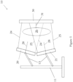
- the x-ray imaging device 10 includes two planar panels 20, 21 each comprising an array of x-ray emitters and collimators.
- the panels 20, 21 are held in place by arms 13 extending away from a support 11. It is understood, however, that these are merely examples, and other methods and structures may be used to hold the panels and detector(s) in place.
- the panels' central panel axes are indicated by lines 28 projecting perpendicularly outwardly from the centre of the front surface of each panel.
- Each panel 20, 21 produces x-rays which emerge from the front faces of the panels.
- the outer limits of the x-ray envelope are shown by lines 24, 25.
- the x-rays are directed at the subject 26 and converge towards a detector 30 in the form of a panel located behind the subject, relative to the panels 20, 21.
- a central detector panel axis 31 is indicated by a line projecting perpendicularly outwardly from the centre of its front surface.
- the panels 20, 21 are emitter arrays, each packaged with its own cathode, anode and vacuum enclosure and powered either by a shared high voltage supply or by individual supplies to each emitter.
- the angle between the central panel axes 28 may be related to the opening angle of the collimators (common collimator angle) provided in the panels for collimating the produced x-rays. In one example, the angle between the central panel axes 28 is approximately the same as the opening angle of the collimators (the common collimator angle).
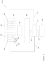
- the x-ray imaging device 10A comprises two panels 20, 21 shown by way of example with not-to-scale x-ray emitters 40 and collimators 50.
- the detector 30 is connected 32 to a controller 55 which in turn is connected 52 to a display 60.
- x-rays are emitted from the collimators 50 in conelets 51 having central conelet axes 52.
- the signals received by the detector 30 are processed by either the controller 55 and/or the display 60 to produce an image on the display for review.
- the controller 55 is also connected 54 to the panels 20, 21 to thereby control the emission of x-rays. For instance, the controller can control which emitters are used to provide x-rays which emerge from the panels.
- the controller can control the synchronisation, sequencing and other characteristics of the emitted x-rays to produce defined areas and directions of x-rays for impinging on the subject 26.
- the controller may do this by controlling solenoids for selectively bending a path of electrons, produced by electron emitters, so that it either impinges on high energy x-ray producing material or onto absorbing (low energy x-ray producing) material.
- the controller is also connected to the detector 30 and so it is possible to manipulate the data defining which emitters are emitting x-rays with the received signals so that over time 3D images may be created.
- FIG 3 shows a four panel source configured in a 2x2 array 100 from above.
- the panels are arranged to emit x-rays in an approximately horizontal direction.
- Each panel comprises a substantially rectangular block with a major plane forming the front surface from which the x-rays are emitted, in use. Only the top two panels 120, 121 are visible.
- Each panel has been rotated about a vertical axis by an angle 130 away from, and out of, a vertical "emitter" plane 131 so that the major plane of each panel is now not vertical.
- This angle 130 may be approximately half the common collimator angle.
- the panels have been angled inwards in this manner so that the angle between the front face of each panel is now less than 180 degrees.
- each panel has been rotated about a horizontal axis which extends along the centre of the major plane of each panel from side to side. In this way the panels have been "angled-down". The angle through which they have been angled-down may also be approximately the same as the common collimator angle.
- the imaginary central panel axes 28 are shown to aid the understanding of the figure.
- Figure 4 shows this angling-down more clearly as it shows the side view of the same 2x2 array 100 of Figure 3 .
- one of the top panels 121 and one of the bottom panels 122 are shown. It can be seen that the bottom panel 122 has been angled upwardly and the top panel has been angled downwardly.
- the top panel 121 has been moved through an angle 140 away from the vertical "emitter" plane 131 about the horizontal axis described in relation to Figure 3 .
- This angle 140 may be approximately the same as the common collimator angle.
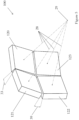
- Figure 5 shows a perspective view of the four panel array of Figures 3 and 4 . It can be seen how the four panels 120, 121, 122, 123 are arranged in a 2x2 square pattern. The panels have been angled inwardly such that their central axes 28 all converge to a common single point 29. This common point 29 may lie on an imaginary line extending outwardly from the centre of the array 100 at a common angle to the plane of each of the four panels. However, in some circumstances the panels in the top row have a first common point and the panels in the second row have a second common point. It is possible that the first and second common points both lie on an imaginary line extending outwardly from the centre of the array 100 at a common angle to the plane of each of the four panels.
- the top panels 120, 121 have been angled in such that their front face planes are not in the same plane. The angle between those planes is shown by reference 33.
- the bottom two panels 122, 123 are oriented relative to each other in a similar manner.
- the bottom panels 122, 123 have also been angled in relative to the top two panels 120, 121 such that the angle between the front face planes of one top panel 121 and one bottom panel 122 is shown by reference 39.
- the angle 33 between the planes is approximately the same as the opening angle of the collimators (the common collimator angle).
- a numerical mapping plane can be introduced in front of an emitter plane. This mapping plane may be parallel to the emitter plane. All stretching and deformations of images due to known tilts and rotations can be applied and the resulting corrected projections are placed on the centre of the mapping plane. When the geometry is known exactly the images have the same shape and size (assuming identical or at least known collimation angles). For "unknown" dislocations in the relative positions of the sources and detectors, the corresponding images will be mapped away from the centre of the mapping plane in a deterministic pattern.
- the device may be pre-calibrated at the time of manufacture so that the relative orientation and positions of the emitters and detector are known.
- the device may be calibrated after manufacture. This may be necessary where the relative positions of one or more emitter panels and the detector have changed.
- the calibration may be undertaken by emitting x-rays from various emitters in a predetermined sequence, with no subject present, and identifying where they are received on the detector.
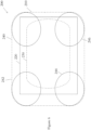
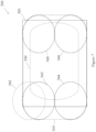
- Figure 6 shows a detector plane view 200 for a single panel emitter array and shows the active area of a detector 220 relative to a region of interest 230, and the outer envelope of the x-ray field 210.
- the relative positions and coverage areas of the x-ray cones produced from the four corner emitters in the array of emitters in the single panel are indicated as circles 240, 242, 244, 246, one in each corner of the envelope 210.
- Figure 7 shows a detector plane view for a two panel emitter array source set-up as shown in Figure 1 where the two panels have been angled-in towards one another each about a horizontal axis passing through the centre of each panel from side to side.
- the active area of the detector 320 relative to a region of interest 330 is shown, as before, but the outer envelope of the x-ray field 310 has narrowed in the vertical plane. This is demonstrated by the relative positions and coverage areas of the x-rays from the upper two corner emitters of the top panel 20 and the lower two corner emitters from the bottom panel 21 being indicated as circles 340, 342, 344, 346, one in each corner of the envelope 310.
- Figure 8 shows a detector plane view for a four panel emitter array source set-up as shown in Figures 3 to 5 where the two upper panels 120, 121 have been angled-down and inwardly towards one another, and the two lower panels 122 have been angled upwardly and inwardly towards one another so that the x-rays produced by the 4 panel device converge towards one another.
- the active area of the detector 420 relative to a region of interest 430 is shown, as before, but the outer envelope of the x-ray field 410 has narrowed in both the horizontal and the vertical plane.
- This effect reduces stray x-rays travelling beyond the detector, which is beneficial to operators. Furthermore, it removes the need for a mask to be used around the emitters and/or detector to safely absorb such stray and unwanted x-rays.
- any number of panels may be employed in any regular, or irregular, pattern. For instance, a 6x2 array, a 3x3 array and so on. Some or all of the panels may be angled-in towards each other to converge the beam of x-rays so that a more focussed x-ray envelope may be produced.
- the following table provides information on the possible conelet angles (common collimator angles) for various applications, together with the likely number of panels, the number of simultaneous conelets (i.e. the number of emitters firing simultaneously), and the ratio of conelet size (e.g. diameter or area) to detector size (e.g. width or length, or area) for a multi-panel array.
- the ratio of conelet size to detector size reduces. Therefore, the number of conelets required to image an object is increased. This allows greater control over what part of an object is struck by x-rays leading to greater optimisation of the process and less dosage.
- the contrasting angle from the multiple panels also allows for a greater depth of resolution.
- the ratio of the conelet size to the detector size may be represented as 1 / (no. of panels across + 2) ⁇ ratio of the conelet size to the detector ⁇ 0.7.
- Application Conelet angle Number of panels Number of simultaneous conelets Ratio of conelet size to detector size in multi-panel cases
Landscapes
- Health & Medical Sciences (AREA)
- Life Sciences & Earth Sciences (AREA)
- Engineering & Computer Science (AREA)
- Medical Informatics (AREA)
- Physics & Mathematics (AREA)
- High Energy & Nuclear Physics (AREA)
- Radiology & Medical Imaging (AREA)
- Animal Behavior & Ethology (AREA)
- Optics & Photonics (AREA)
- Pathology (AREA)
- Biophysics (AREA)
- Biomedical Technology (AREA)
- Heart & Thoracic Surgery (AREA)
- Molecular Biology (AREA)
- Surgery (AREA)
- Nuclear Medicine, Radiotherapy & Molecular Imaging (AREA)
- General Health & Medical Sciences (AREA)
- Public Health (AREA)
- Veterinary Medicine (AREA)
- General Physics & Mathematics (AREA)
- Spectroscopy & Molecular Physics (AREA)
- General Engineering & Computer Science (AREA)
- Apparatus For Radiation Diagnosis (AREA)
Claims (14)
- Ein Röntgenbildgebungsgerät (10), das mindestens zwei im Wesentlichen planare Paneele (20, 21) umfasst, wobei jedes Paneel eine Vielzahl von Röntgenstrahlern (40) in einem Vakuumgehäuse umfasst, wobei jeder Röntgenstrahler Röntgenstrahlen in einem Kegelchen (51) mit einer zentralen Kegelachse (52) emittiert, und jedes Paneel so angeordnet ist, dass die zentralen Kegelachsen jedes Röntgenstrahlers in jedem jeweiligen Paneel parallel zueinander sind, wobei die mindestens zwei Paneele jeweils eine zentrale Paneelachse (28) haben und so angeordnet sind, dass ihre zentralen Paneelachsen nicht parallel zueinander sind, und wobei die zentralen Paneelachsen in einer gemeinsamen Ebene liegen, wobei das Gerät ferner ein Paneelhaltemittel (11, 13) umfasst, das so angeordnet ist, dass das Paneelhaltemittel die mindestens zwei Paneele stationär in Bezug auf ein Objekt während der Röntgenaufnahme des Objekts hält, wobei jeder Röntgenstrahler einen Kollimator (50) mit einem gemeinsamen Kollimatorwinkel umfasst und die Paneele so angeordnet sind, dass der Winkel zwischen ihren zentralen Paneelachsen (28) ungefähr dem gemeinsamen Kollimatorwinkel entspricht, und wobei der gemeinsame Kollimatorwinkel den Winkel der Kegelchen bestimmt.
- Das Röntgenbildgebungsgerät (10) nach Anspruch 1, mit n Paneelen, wobei n mehr als zwei ist, die nebeneinander in einer linearen Anordnung angeordnet sind, wobei jede mit ihrer zentralen Paneelachse in einer gemeinsamen Ebene liegt, wobei jeder Röntgenstrahler einen Kollimator mit einem gemeinsamen Kollimatorwinkel umfasst und die beiden äußeren Paneele der Anordnung so angeordnet sind, dass der Winkel zwischen ihren zentralen Paneelachsen ungefähr dem gemeinsamen Kollimatorwinkel entspricht, und jedes dazwischenliegende Paneel so angeordnet ist, dass der Winkel zwischen seiner zentralen Paneelachse und der des angrenzenden Paneels durch die Formel (der gemeinsame Kollimatorwinkel)/(n-1) berechnet wird.
- Das Röntgenbildgebungsgerät (10) nach Anspruch 1, mit einer Anordnung von vier oder mehr Paneelen, die in zwei oder mehr Reihen angeordnet sind, wobei jedes Paneel so angeordnet ist, dass ihre zentralen Paneelachsen sich auf einem gemeinsamen Punkt distal vom Gerät konvergieren, wobei jeder Röntgenstrahler einen Kollimator mit einem gemeinsamen Kollimatorwinkel umfasst und die Paneele an den Enden jeder Reihe so angeordnet sind, dass der Winkel zwischen ihren zentralen Paneelachsen und einer Linie, die den gemeinsamen Punkt mit dem Zentrum der Anordnung der Paneele verbindet, ungefähr dem gemeinsamen Kollimatorwinkel entspricht.
- Das Röntgenbildgebungsgerät (10) nach Anspruch 1, mit einer Anordnung von sechs oder mehr Paneelen, die in zwei oder mehr Reihen angeordnet sind, wobei jedes Paneel in einer ersten Reihe so angeordnet ist, dass ihre zentralen Paneelachsen sich auf einem ersten gemeinsamen Punkt distal vom Gerät konvergieren, und jedes Paneel in jeder nachfolgenden Reihe so angeordnet ist, dass ihre zentralen Paneelachsen sich auf jeweiligen nachfolgenden gemeinsamen Punkten distal vom Gerät konvergieren, wobei jeder Röntgenstrahler einen Kollimator mit einem gemeinsamen Kollimatorwinkel umfasst und die Paneele an den Enden jeder Reihe so angeordnet sind, dass der Winkel zwischen ihren zentralen Paneelachsen und einer Linie, die den relevanten gemeinsamen Punkt mit dem Zentrum der Anordnung der Paneele in dieser Reihe verbindet, ungefähr dem gemeinsamen Kollimatorwinkel entspricht.
- Das Röntgenbildgebungsgerät (10) nach einem der vorhergehenden Ansprüche, wobei der gemeinsame Kollimatorwinkel im Bereich von 10 bis 45 Grad liegt.
- Das Röntgenbildgebungsgerät (10) nach einem der vorhergehenden Ansprüche, ferner umfassend einen digitalen Röntgendetektor (30) mit einer zentralen Detektor-Paneelachse (31) und einen Controller zur individuellen Steuerung jedes Röntgenstrahlers.
- Das Röntgenbildgebungsgerät (10) nach Anspruch 6, ferner umfassend Detektorhaltemittel, und so angeordnet, dass das Detektorhaltemittel den Detektor stationär in Bezug auf das Objekt während der Röntgenaufnahme des Objekts hält.
- Das Röntgenbildgebungsgerät (10) nach einem der Ansprüche 6 und 7, ferner umfassend einen Prozessor zur Verarbeitung von Daten, die durch den Detektor als Ergebnis des Empfangs von Röntgenstrahlen erzeugt werden, und zur Erzeugung eines Bildes.
- Das Röntgenbildgebungsgerät (10) nach Anspruch 8, wobei der Prozessor konfiguriert ist, Daten, die über einen Zeitraum empfangen wurden, zu verarbeiten, um ein 3D-Tomosynthese-Modell eines geröntgten Objekts zu erzeugen, wobei die empfangenen Röntgenstrahlen von verschiedenen Strahlern in den Paneelen emittiert wurden und das Objekt in verschiedenen Richtungen durchdrungen haben.
- Das Röntgenbildgebungsgerät (10) nach einem der Ansprüche 8 und 9, wobei der Prozessor konfiguriert ist, den relativen Winkel der zentralen Paneelachse jedes Paneels relativ zur zentralen Detektor-Paneelachse (31) in zwei der drei Kardinalachsen zu bestimmen.
- Das Röntgenbildgebungsgerät (10) nach einem der vorhergehenden Ansprüche, ferner umfassend Positionierungsmittel zur Anpassung der Position von mindestens einem der mindestens zwei Paneele relativ zu dem anderen der mindestens zwei Paneele, vor der Röntgenaufnahme des Objekts.
- Ein Verfahren zur Erzeugung eines Röntgenbildes eines Objekts, umfassend die Schritte des Bereitstellens eines Röntgenbildgebungsgeräts (10) gemäß Anspruch 8; Bereitstellen eines Objekts zwischen dem Detektor und den Paneelen; Veranlassen, dass Röntgenstrahlen von den Paneelen emittiert werden; Verarbeiten von Daten, die durch den Detektor (30) als Ergebnis des Empfangs von Röntgenstrahlen empfangen werden; und Erzeugen eines Bildes daraus.
- Ein Verfahren zur Erzeugung eines Röntgenbildes eines Objekts gemäß Anspruch 12, ferner umfassend den Schritt des Verwendens des Prozessors zur Bestimmung des relativen Winkels der zentralen Paneelachse jedes Paneels relativ zur zentralen Detektor-Paneelachse (31) des Detektors (30) in zwei der drei Kardinalachsen, um die Genauigkeit des erzeugten Bildes zu verbessern.
- Das Verfahren zur Erzeugung eines Röntgenbildes eines Objekts gemäß einem der Ansprüche 12 und 13, ferner umfassend den Schritt des Empfangens von Daten durch den Detektor (30) über einen Zeitraum, wobei die empfangenen Röntgenstrahlen von verschiedenen Strahlern in den Paneelen emittiert wurden und das Objekt in verschiedenen Richtungen durchdrungen haben, und der Prozessor verarbeitet die genannten Daten, um ein 3D-Tomosynthese-Modell des Objekts zu erzeugen.
Applications Claiming Priority (2)
| Application Number | Priority Date | Filing Date | Title |
|---|---|---|---|
| GB1719599.1A GB2568735A (en) | 2017-11-25 | 2017-11-25 | An x-ray imaging system |
| PCT/GB2018/053400 WO2019102216A1 (en) | 2017-11-25 | 2018-11-23 | An x-ray imaging device |
Publications (3)
| Publication Number | Publication Date |
|---|---|
| EP3713490A1 EP3713490A1 (de) | 2020-09-30 |
| EP3713490C0 EP3713490C0 (de) | 2025-03-26 |
| EP3713490B1 true EP3713490B1 (de) | 2025-03-26 |
Family
ID=60950655
Family Applications (1)
| Application Number | Title | Priority Date | Filing Date |
|---|---|---|---|
| EP18819333.8A Active EP3713490B1 (de) | 2017-11-25 | 2018-11-23 | Röntgenbildgebungsvorrichtung |
Country Status (12)
| Country | Link |
|---|---|
| US (1) | US11234669B2 (de) |
| EP (1) | EP3713490B1 (de) |
| JP (1) | JP7385564B2 (de) |
| KR (1) | KR102711558B1 (de) |
| CN (1) | CN111386077B (de) |
| AU (1) | AU2018372073B2 (de) |
| BR (1) | BR112020009970A2 (de) |
| CA (1) | CA3083070A1 (de) |
| ES (1) | ES3023045T3 (de) |
| GB (1) | GB2568735A (de) |
| WO (1) | WO2019102216A1 (de) |
| ZA (1) | ZA202003766B (de) |
Families Citing this family (3)
| Publication number | Priority date | Publication date | Assignee | Title |
|---|---|---|---|---|
| GB2587597B (en) | 2019-09-12 | 2023-08-23 | Adaptix Ltd | An x-ray digital tomosynthesis system and method |
| GB2618084A (en) * | 2022-04-25 | 2023-11-01 | Adaptix Ltd | A method of analysing a geological sample |
| WO2025131290A1 (en) * | 2023-12-21 | 2025-06-26 | Brainlab Ag | Computer-implemented method for medical imaging |
Citations (1)
| Publication number | Priority date | Publication date | Assignee | Title |
|---|---|---|---|---|
| US20150282774A1 (en) * | 2012-08-17 | 2015-10-08 | The University Of North Carolina At Chapel Hill | Stationary gantry computed tomography systems and methods with distributed x-ray source arrays |
Family Cites Families (23)
| Publication number | Priority date | Publication date | Assignee | Title |
|---|---|---|---|---|
| US6242743B1 (en) * | 1998-08-11 | 2001-06-05 | Mosaic Imaging Technology, Inc. | Non-orbiting tomographic imaging system |
| JP3911603B2 (ja) * | 2001-08-29 | 2007-05-09 | 株式会社日立製作所 | X線ct装置 |
| CN100398066C (zh) * | 2002-03-13 | 2008-07-02 | 分离成像有限责任公司 | 准同步多平面x射线成像的系统和方法 |
| GB0525593D0 (en) * | 2005-12-16 | 2006-01-25 | Cxr Ltd | X-ray tomography inspection systems |
| US7123689B1 (en) * | 2005-06-30 | 2006-10-17 | General Electric Company | Field emitter X-ray source and system and method thereof |
| US7302031B2 (en) * | 2005-10-27 | 2007-11-27 | Sectra Mamea Ab | Method and arrangement relating to X-ray imaging |
| US20100189223A1 (en) * | 2006-02-16 | 2010-07-29 | Steller Micro Devices | Digitally addressed flat panel x-ray sources |
| JP5575666B2 (ja) | 2008-02-22 | 2014-08-20 | コーニンクレッカ フィリップス エヌ ヴェ | 分散型線源によるx線イメージングのための高解像度の略静的セットアップ |
| FI123452B (fi) * | 2008-10-03 | 2013-05-15 | Palodex Group Oy | Menetelmä ja sen toteuttava laite röntgenkuvauksen suorittamiseksi |
| DE102008050571A1 (de) * | 2008-10-06 | 2010-04-15 | Siemens Aktiengesellschaft | Tomosynthesegerät und Verfahren zum Betrieb eines Tomosynthesegerätes |
| JP5658449B2 (ja) * | 2008-10-20 | 2015-01-28 | ゼネラル・エレクトリック・カンパニイ | X線撮像の方法及びシステム |
| WO2011106433A1 (en) * | 2010-02-24 | 2011-09-01 | Accuray Incorporated | Gantry image guided radiotherapy system and related treatment delivery methods |
| WO2012106204A1 (en) * | 2011-01-31 | 2012-08-09 | University Of Massachusetts | Tomosynthesis imaging |
| US9012859B2 (en) * | 2012-05-18 | 2015-04-21 | General Electric Company | Tiled X-ray imager panel and method of forming the same |
| WO2014075699A1 (de) | 2012-11-16 | 2014-05-22 | Böhme Medizintechnik GmbH | Röntgenologischer arbeitsplatz |
| US9001962B2 (en) | 2012-12-20 | 2015-04-07 | Triple Ring Technologies, Inc. | Method and apparatus for multiple X-ray imaging applications |
| CN104981205B (zh) | 2013-01-23 | 2018-09-21 | 卡尔斯特里姆保健公司 | 用于断层融合的定向x射线场 |
| CN105682553A (zh) * | 2013-10-22 | 2016-06-15 | 皇家飞利浦有限公司 | 用于采集对象的图像的x射线系统特别是断层摄影组合系统和方法 |
| GB2523796A (en) * | 2014-03-05 | 2015-09-09 | Adaptix Ltd | X-ray generator |
| US11051771B2 (en) * | 2014-06-17 | 2021-07-06 | Xintek, Inc. | Stationary intraoral tomosynthesis imaging systems, methods, and computer readable media for three dimensional dental imaging |
| US10980494B2 (en) * | 2014-10-20 | 2021-04-20 | The University Of North Carolina At Chapel Hill | Systems and related methods for stationary digital chest tomosynthesis (s-DCT) imaging |
| US9775579B2 (en) * | 2015-02-18 | 2017-10-03 | Guy M. Besson | Multi-source CT system and imaging method |
| WO2017185028A1 (en) | 2016-04-22 | 2017-10-26 | Hologic, Inc. | Tomosynthesis with shifting focal spot x-ray system using an addressable array |
-
2017
- 2017-11-25 GB GB1719599.1A patent/GB2568735A/en not_active Withdrawn
-
2018
- 2018-11-23 JP JP2020524885A patent/JP7385564B2/ja active Active
- 2018-11-23 ES ES18819333T patent/ES3023045T3/es active Active
- 2018-11-23 CA CA3083070A patent/CA3083070A1/en active Pending
- 2018-11-23 US US16/766,722 patent/US11234669B2/en active Active
- 2018-11-23 AU AU2018372073A patent/AU2018372073B2/en active Active
- 2018-11-23 BR BR112020009970-8A patent/BR112020009970A2/pt not_active Application Discontinuation
- 2018-11-23 CN CN201880075270.5A patent/CN111386077B/zh active Active
- 2018-11-23 KR KR1020207017078A patent/KR102711558B1/ko active Active
- 2018-11-23 WO PCT/GB2018/053400 patent/WO2019102216A1/en not_active Ceased
- 2018-11-23 EP EP18819333.8A patent/EP3713490B1/de active Active
-
2020
- 2020-06-22 ZA ZA2020/03766A patent/ZA202003766B/en unknown
Patent Citations (1)
| Publication number | Priority date | Publication date | Assignee | Title |
|---|---|---|---|---|
| US20150282774A1 (en) * | 2012-08-17 | 2015-10-08 | The University Of North Carolina At Chapel Hill | Stationary gantry computed tomography systems and methods with distributed x-ray source arrays |
Also Published As
| Publication number | Publication date |
|---|---|
| US11234669B2 (en) | 2022-02-01 |
| GB2568735A (en) | 2019-05-29 |
| CN111386077A (zh) | 2020-07-07 |
| ZA202003766B (en) | 2021-07-28 |
| WO2019102216A1 (en) | 2019-05-31 |
| EP3713490A1 (de) | 2020-09-30 |
| US20200383656A1 (en) | 2020-12-10 |
| AU2018372073A1 (en) | 2020-07-02 |
| KR102711558B1 (ko) | 2024-09-27 |
| JP7385564B2 (ja) | 2023-11-22 |
| GB201719599D0 (en) | 2018-01-10 |
| CN111386077B (zh) | 2024-05-14 |
| KR20200091879A (ko) | 2020-07-31 |
| JP2021503977A (ja) | 2021-02-15 |
| ES3023045T3 (en) | 2025-05-29 |
| EP3713490C0 (de) | 2025-03-26 |
| BR112020009970A2 (pt) | 2020-11-03 |
| AU2018372073B2 (en) | 2024-05-02 |
| CA3083070A1 (en) | 2019-05-31 |
Similar Documents
| Publication | Publication Date | Title |
|---|---|---|
| US6914959B2 (en) | Combined radiation therapy and imaging system and method | |
| US8300766B2 (en) | Radio tomography imaging method | |
| EP2948061B1 (de) | Gerichtete röntgenfelder für tomosynthese | |
| CN109310384B (zh) | 用于4d成像的多射束x射线暴露的系统和方法 | |
| EP3713490B1 (de) | Röntgenbildgebungsvorrichtung | |
| EP2907452B1 (de) | Fotosteuerungsvorrichtung, fotografisches system, fotosteuerungsverfahren und programm | |
| JP5031095B2 (ja) | 放射線断層撮影方法および放射線治療装置制御装置 | |
| EP3103394B1 (de) | Röntgenbildgebungsvorrichtung | |
| KR102139661B1 (ko) | 회전 가능한 시준기를 구비한 ct 시스템 | |
| CN106419947A (zh) | 用于层析x射线照相组合图像采集的系统以及方法 | |
| US11291865B2 (en) | Verification system for robotic radiosurgery | |
| KR20180057024A (ko) | 분할형 필터를 구비한 듀얼 에너지 방식의 콘 빔 컴퓨터 단층 촬영장치 | |
| KR20180042572A (ko) | 가변형 디텍터 어레이를 갖는 엑스선 영상 촬영 장치 | |
| JP7443153B2 (ja) | X線コンピュータ断層撮影装置および体重分布シート | |
| WO2022185172A1 (en) | An x-ray imaging apparatus | |
| AU2022230799A1 (en) | An x-ray imaging apparatus | |
| WO2025071569A1 (en) | Chair-side intraoral tomosynthesis apparatus and methods | |
| KR20180057015A (ko) | 필터를 구비한 듀얼 에너지 방식의 콘 빔 컴퓨터 단층촬영장치 |
Legal Events
| Date | Code | Title | Description |
|---|---|---|---|
| STAA | Information on the status of an ep patent application or granted ep patent |
Free format text: STATUS: UNKNOWN |
|
| STAA | Information on the status of an ep patent application or granted ep patent |
Free format text: STATUS: THE INTERNATIONAL PUBLICATION HAS BEEN MADE |
|
| PUAI | Public reference made under article 153(3) epc to a published international application that has entered the european phase |
Free format text: ORIGINAL CODE: 0009012 |
|
| STAA | Information on the status of an ep patent application or granted ep patent |
Free format text: STATUS: REQUEST FOR EXAMINATION WAS MADE |
|
| 17P | Request for examination filed |
Effective date: 20200610 |
|
| AK | Designated contracting states |
Kind code of ref document: A1 Designated state(s): AL AT BE BG CH CY CZ DE DK EE ES FI FR GB GR HR HU IE IS IT LI LT LU LV MC MK MT NL NO PL PT RO RS SE SI SK SM TR |
|
| AX | Request for extension of the european patent |
Extension state: BA ME |
|
| DAV | Request for validation of the european patent (deleted) | ||
| DAX | Request for extension of the european patent (deleted) | ||
| STAA | Information on the status of an ep patent application or granted ep patent |
Free format text: STATUS: EXAMINATION IS IN PROGRESS |
|
| 17Q | First examination report despatched |
Effective date: 20220506 |
|
| P01 | Opt-out of the competence of the unified patent court (upc) registered |
Effective date: 20230607 |
|
| GRAP | Despatch of communication of intention to grant a patent |
Free format text: ORIGINAL CODE: EPIDOSNIGR1 |
|
| STAA | Information on the status of an ep patent application or granted ep patent |
Free format text: STATUS: GRANT OF PATENT IS INTENDED |
|
| RIC1 | Information provided on ipc code assigned before grant |
Ipc: A61B 6/40 20240101ALI20241118BHEP Ipc: A61B 6/02 20060101ALI20241118BHEP Ipc: A61B 6/06 20060101ALI20241118BHEP Ipc: G21K 1/02 20060101ALI20241118BHEP Ipc: G21K 5/02 20060101ALI20241118BHEP Ipc: H01J 35/16 20060101ALI20241118BHEP Ipc: A61B 6/00 20060101AFI20241118BHEP |
|
| INTG | Intention to grant announced |
Effective date: 20241129 |
|
| GRAS | Grant fee paid |
Free format text: ORIGINAL CODE: EPIDOSNIGR3 |
|
| GRAA | (expected) grant |
Free format text: ORIGINAL CODE: 0009210 |
|
| STAA | Information on the status of an ep patent application or granted ep patent |
Free format text: STATUS: THE PATENT HAS BEEN GRANTED |
|
| AK | Designated contracting states |
Kind code of ref document: B1 Designated state(s): AL AT BE BG CH CY CZ DE DK EE ES FI FR GB GR HR HU IE IS IT LI LT LU LV MC MK MT NL NO PL PT RO RS SE SI SK SM TR |
|
| REG | Reference to a national code |
Ref country code: GB Ref legal event code: FG4D |
|
| REG | Reference to a national code |
Ref country code: CH Ref legal event code: EP |
|
| REG | Reference to a national code |
Ref country code: DE Ref legal event code: R096 Ref document number: 602018080517 Country of ref document: DE |
|
| REG | Reference to a national code |
Ref country code: IE Ref legal event code: FG4D |
|
| U01 | Request for unitary effect filed |
Effective date: 20250410 |
|
| P04 | Withdrawal of opt-out of the competence of the unified patent court (upc) registered |
Free format text: CASE NUMBER: APP_18149/2025 Effective date: 20250415 |
|
| U07 | Unitary effect registered |
Designated state(s): AT BE BG DE DK EE FI FR IT LT LU LV MT NL PT RO SE SI Effective date: 20250416 |
|
| REG | Reference to a national code |
Ref country code: ES Ref legal event code: FG2A Ref document number: 3023045 Country of ref document: ES Kind code of ref document: T3 Effective date: 20250529 |
|
| PG25 | Lapsed in a contracting state [announced via postgrant information from national office to epo] |
Ref country code: RS Free format text: LAPSE BECAUSE OF FAILURE TO SUBMIT A TRANSLATION OF THE DESCRIPTION OR TO PAY THE FEE WITHIN THE PRESCRIBED TIME-LIMIT Effective date: 20250626 |
|
| PG25 | Lapsed in a contracting state [announced via postgrant information from national office to epo] |
Ref country code: NO Free format text: LAPSE BECAUSE OF FAILURE TO SUBMIT A TRANSLATION OF THE DESCRIPTION OR TO PAY THE FEE WITHIN THE PRESCRIBED TIME-LIMIT Effective date: 20250626 |
|
| PG25 | Lapsed in a contracting state [announced via postgrant information from national office to epo] |
Ref country code: HR Free format text: LAPSE BECAUSE OF FAILURE TO SUBMIT A TRANSLATION OF THE DESCRIPTION OR TO PAY THE FEE WITHIN THE PRESCRIBED TIME-LIMIT Effective date: 20250326 |
|
| PG25 | Lapsed in a contracting state [announced via postgrant information from national office to epo] |
Ref country code: GR Free format text: LAPSE BECAUSE OF FAILURE TO SUBMIT A TRANSLATION OF THE DESCRIPTION OR TO PAY THE FEE WITHIN THE PRESCRIBED TIME-LIMIT Effective date: 20250627 |
|
| PG25 | Lapsed in a contracting state [announced via postgrant information from national office to epo] |
Ref country code: SM Free format text: LAPSE BECAUSE OF FAILURE TO SUBMIT A TRANSLATION OF THE DESCRIPTION OR TO PAY THE FEE WITHIN THE PRESCRIBED TIME-LIMIT Effective date: 20250326 |
|
| PG25 | Lapsed in a contracting state [announced via postgrant information from national office to epo] |
Ref country code: PL Free format text: LAPSE BECAUSE OF FAILURE TO SUBMIT A TRANSLATION OF THE DESCRIPTION OR TO PAY THE FEE WITHIN THE PRESCRIBED TIME-LIMIT Effective date: 20250326 |
|
| PG25 | Lapsed in a contracting state [announced via postgrant information from national office to epo] |
Ref country code: SK Free format text: LAPSE BECAUSE OF FAILURE TO SUBMIT A TRANSLATION OF THE DESCRIPTION OR TO PAY THE FEE WITHIN THE PRESCRIBED TIME-LIMIT Effective date: 20250326 |
|
| PG25 | Lapsed in a contracting state [announced via postgrant information from national office to epo] |
Ref country code: IS Free format text: LAPSE BECAUSE OF FAILURE TO SUBMIT A TRANSLATION OF THE DESCRIPTION OR TO PAY THE FEE WITHIN THE PRESCRIBED TIME-LIMIT Effective date: 20250726 |
|
| U20 | Renewal fee for the european patent with unitary effect paid |
Year of fee payment: 8 Effective date: 20251023 |
|
| REG | Reference to a national code |
Ref country code: CH Ref legal event code: U11 Free format text: ST27 STATUS EVENT CODE: U-0-0-U10-U11 (AS PROVIDED BY THE NATIONAL OFFICE) Effective date: 20251201 |