EP3713404B1 - Submerged feed disperser for aquaculture system - Google Patents
Submerged feed disperser for aquaculture system Download PDFInfo
- Publication number
- EP3713404B1 EP3713404B1 EP18881582.3A EP18881582A EP3713404B1 EP 3713404 B1 EP3713404 B1 EP 3713404B1 EP 18881582 A EP18881582 A EP 18881582A EP 3713404 B1 EP3713404 B1 EP 3713404B1
- Authority
- EP
- European Patent Office
- Prior art keywords
- fish
- dispersing
- helical
- fish feed
- feed
- Prior art date
- Legal status (The legal status is an assumption and is not a legal conclusion. Google has not performed a legal analysis and makes no representation as to the accuracy of the status listed.)
- Active
Links
Images



Classifications
-
- A—HUMAN NECESSITIES
- A01—AGRICULTURE; FORESTRY; ANIMAL HUSBANDRY; HUNTING; TRAPPING; FISHING
- A01K—ANIMAL HUSBANDRY; AVICULTURE; APICULTURE; PISCICULTURE; FISHING; REARING OR BREEDING ANIMALS, NOT OTHERWISE PROVIDED FOR; NEW BREEDS OF ANIMALS
- A01K61/00—Culture of aquatic animals
- A01K61/80—Feeding devices
-
- A—HUMAN NECESSITIES
- A01—AGRICULTURE; FORESTRY; ANIMAL HUSBANDRY; HUNTING; TRAPPING; FISHING
- A01K—ANIMAL HUSBANDRY; AVICULTURE; APICULTURE; PISCICULTURE; FISHING; REARING OR BREEDING ANIMALS, NOT OTHERWISE PROVIDED FOR; NEW BREEDS OF ANIMALS
- A01K61/00—Culture of aquatic animals
- A01K61/60—Floating cultivation devices, e.g. rafts or floating fish-farms
-
- Y—GENERAL TAGGING OF NEW TECHNOLOGICAL DEVELOPMENTS; GENERAL TAGGING OF CROSS-SECTIONAL TECHNOLOGIES SPANNING OVER SEVERAL SECTIONS OF THE IPC; TECHNICAL SUBJECTS COVERED BY FORMER USPC CROSS-REFERENCE ART COLLECTIONS [XRACs] AND DIGESTS
- Y02—TECHNOLOGIES OR APPLICATIONS FOR MITIGATION OR ADAPTATION AGAINST CLIMATE CHANGE
- Y02A—TECHNOLOGIES FOR ADAPTATION TO CLIMATE CHANGE
- Y02A40/00—Adaptation technologies in agriculture, forestry, livestock or agroalimentary production
- Y02A40/80—Adaptation technologies in agriculture, forestry, livestock or agroalimentary production in fisheries management
- Y02A40/81—Aquaculture, e.g. of fish
Definitions
- a fish pen that is anchored to the ocean floor.
- a fish pen includes four spar buoys with damper plates coupled to the bottom that dampen the buoy motion caused by wave action.
- the four spar buoys are typically arranged in a rectangular array with a net fastened to the spar buoys to define a box-like enclosure.
- Anchor lines extend outwardly and downwardly from each spar buoy to support the nets.
- a submerged feed disperser system for an open sea fish pen is disclosed herein that increases the effective volume over which feed is delivered inside a fish pen in a submerged state.
- the feed disperser allows more fish to eat to satiation by reducing competition for feed.
- the reduced competition for feed encourages consistent fish growth within a population, while reducing aggression during feeding, and reducing the loss or waste of feed pellets during feeding.
- the feed disperser has also been found to produce an improved coefficient of variation in fish size by allowing less aggressive fish to more easily acquire and consume feed, decreasing fish mortality and improving the feed conversion ratio.
- the feed disperser has been found to reduce damage to pelletized fish feed during dispersal of the feed.
- U.S. Pat. No. 7,743,733, to Harrison et al. discloses an offshore aquaculture system including a fish feeding apparatus configured to dispense a slurry containing fish feed in streams upwardly and outwardly from a dispenser head at a number of circumferentially spaced outlets at the water surface.
- U.S. Pat. No. 9,655,347 discloses an open ocean fish farm structure including a feeding system that distributes fish feed through a plurality of individual feeder hoses, each hose extending from a feed storage bin to a point on the upper aspect of the surface of the fish enclosure.
- U.S. Pat. No. 9,326,493, to Han et al. discloses an automatic feeding system for an underwater farm with a single feeding hose that is connected to a mixing tank containing the fish feed, and extends to the underwater fish farm.
- JP 2003 158949 A discloses a feeding system comprising a storage connected to an inclined helical tube provided with apertures along its length which allow to dispense food from the storage due to gravity.
- the feeding system is suspended above a water surface.
- Each aperture (except the last one) is provided with a shutter which is computer-controlled to be open or closed. If a shutter is opened, all feed in the inclined tube is dropped in the corresponding aperture.
- the invention provides according to independent claim 1 a submergible fish feed dispersing apparatus configured to deliver feed inside an aquaculture fish pen in a submerged state, the fish feed dispersing apparatus including a flexible helical dispersing tube having an inlet that receives fish feed from a source. A plurality of spaced-apart apertures in the helical dispersing tube disperse the received fish feed.
- a mounting assembly with two spaced-apart attachment members is fixed to the fish pen with a plurality of elongate members extending between the two spaced-apart attachment members.
- a number of hanger subassemblies are adjustably supported on the plurality of elongate members.
- Each hanger subassembly has a proximal end attached to a corresponding one of the elongate members and a distal end with a clamp configured to engage the helical dispersing tube.
- the mounting assembly is configured to control the pitch of the helical dispersing tube.
- the plurality of apertures are not aligned on the helical feed dispersing tube.
- the plurality of apertures open outwardly away from the helical dispersing tube.
- the two attachment members are configured to be fixed to a spar buoy of the fish pen.
- the helical dispersing tube continuously decreases in elevation such that the plurality of spaced apertures are at different depths.
- a distal end of the helical dispersing tube is an open outlet.
- the helical dispersing tube defines a circular helix.
- each of the hanger subassemblies comprises a first arm that defines the proximal end and the distal end, and further comprising a second arm having a proximal end connected to the corresponding elongate member and a distal end that engages the first arm at a selectable intermediate location on the first arm.
- the plurality of elongate members may have a plurality of apertures for attaching the proximal end of the first arm and the second arm to a selectable location on the corresponding elongate member.
- the pitch of the helical dispersing tube is determined by the selected location of the hanger assemblies on the corresponding elongate members.
- the plurality of hanger subassemblies comprise at least four hanger subassemblies.
- the plurality of apertures disposed at spaced intervals along the helical dispersing tube comprise at least seven apertures.
- first and second arms are configured to pivot toward the corresponding elongate member into a folded position when the helical dispersing tube is removed.
- FIGURE 1 A fish pen 100 with a helical feed dispersing assembly 200 in accordance with the present invention is shown in FIGURE 1 .
- the fish pen 100 includes an elongate center spar buoy 110 that is configured to remain upright in the body of water.
- a lower rim assembly 130 and an upper rim assembly 140 are horizontally disposed about the spar buoy 110, and are attached to the spar buoy 110 with a cable assembly formed from a system of cables 150, 152, 154, 156, and optionally anchored with a mooring line or hawser 133 that is fixed to an object or anchor (not shown) to anchor the fish pen 100.
- An enclosure 160 for example a netting assembly, is supported by the center spar buoy 110 and the rim assemblies 130, 140, and is configured for retaining fish therein.
- the fish pen 100 is configured to be movable between a submerged position wherein substantially all of the enclosure 160 is below the waterline, and a surfaced position wherein at least a portion of the enclosure 160 is above the waterline.
- the center spar fish pens may have more or fewer rim assemblies and different enclosure and/or cabling configurations, as will be apparent to persons of skill in the art.
- the fish pen 100 may be assembled at, and/or towed to, a desired location for raising fish and anchored in place.
- the fish pen 100 allows the fish to be raised in, and benefit from, a natural sea environment while also being protected from predators.
- the fish pen 100 is configured to be towed or otherwise repositioned while fully assembled, and with or without a live fish population, for example, to allow the fish pen to be relocated to optimal locations to accommodate seasonal or weather-related changes.
- a portion of the enclosure 160 is illustrated in cutaway to show an exemplary helical feed dispersing assembly 200 that is mounted to the spar buoy 110 and connected to a feed supply line 202.
- the helical feed disperser 200 is attached to the center spar buoy 110 at a selectable axial location within the enclosure 160, for example, on an upper portion of the spar buoy 110.
- a feed supply line 202 provides fish feed to the feed dispersing assembly 200 from a source of fish feed (not shown) that may be located outside of the enclosure 160.
- the supply line 202 may be fixedly attached to the fish pen 100, or may be deployable, for example, comprising a hose from a supply vessel or barge.
- the feed dispersing assembly 200 includes a helical feed dispersing tube 210 that is configured to increase the effective volume over which fish feed is delivered inside the enclosure 160.
- a helical feed dispersing tube 210 that is configured to increase the effective volume over which fish feed is delivered inside the enclosure 160.
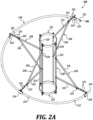
- FIGURE 2A is a perspective view of the feed dispersing assembly 200
- FIGURE 2B is a front view of the dispersing assembly 200
- FIGURE 2C is a plan view of the dispersing assembly 200.
- the feed dispersing assembly 200 includes the helical dispersing tube 210 and an attachment or hanger assembly 220, that attaches the helical dispersing tube 210 to the spar buoy 110 ( FIGURE 1 ) and maintains the dispersing tube 210 in a desired configuration.
- the hanger assembly 220 is adjustable.
- the dispersing tube 210 is flexible, such that the pitch (and axial length) of the helical dispersing tube 210 can be set to provide optimal feed dispersion.
- the adjustable hanger assembly 220 is configured to accommodate different dispersing tubes 210 and to accommodate different pitches for any particular dispersing tube 210.
- the helical dispersing tube 210 in this embodiment is shown with a generally constant diameter, right circular helical shape, it is contemplated that in other embodiments the helical shape may be non-circular, for example elliptical or with sinuous sections, and/or the helical shape may have a non-uniform radius, for example a conical or other non-regular helical shape.
- the dispersing tube 210 has a proximal end 208 that is configured to be connected to the feed supply line 202 with a low-turbulence connection 170, as discussed below and illustrated in FIGURE 4 .
- the dispersing tube 210 has a plurality of spaced-apart apertures 212 distributed along the length of the tube 210 that provide a plurality of outflow feed streams during use. The size, position and orientation of the apertures 212 may be selected to provide a desired outflow volume and dispersal pattern.
- a plurality of interchangeable dispersing tubes 210 are provided, to allow the user to optimize the fish feeding apparatus to accommodate particular fish food characteristics, fish feeding requirements, and the like.
- a distal end 214 of the dispersing tube 210 is preferably open and provides an additional feed stream.
- the distal end 214 may include a flow restrictor (not shown) to achieve a desired pressure in the dispersing tube 210 during use.
- the helical dispersing tube 210 is an HDPE (high density polyethylene) hose and has a length between 6 and 60 m (twenty and two hundred feet), and an inside diameter between 3 and 15 cm (one and six inches), for example, a constant inside diameter of 8 cm (three inches).
- the diameter of the dispersing tube 210 may vary along the length of the dispersing tube 210. As fish feed pellets are pumped into the feed dispersing tube 210 from the supply line 202, a large percentage of the feed is expelled through the apertures 212 along the length of the dispersing tube 210.
- the feed dispersing tube 210 is 15 m (fifty feet) long and has a 8 cm (three-inch) inside diameter.
- the apertures 212 have a diameter between 2,5 cm (1.0 inches) and 3,8 cm (1.5 inches) and are spaced approximately 2 m (six feet) apart along the length of the dispersing tube 210.
- the aperture 212 size and orientations are as follows: (i) a first aperture 212 is located 15 cm (one-half foot) from the proximal end 208 (measured along the tube 210), has a diameter of 3 cm (1 inch), and is oriented outwardly (from the helical feed dispersing tube 210) and zero degrees from horizontal; (ii) a second aperture 212 is located 2 m (seven feet) from the proximal end 208, has a diameter of 3,8 cm (1.5 inches), and is oriented outwardly and zero degrees from horizontal; (iii) a third aperture 212 is located 4 m (fourteen feet) from the proximal end 208, has a diameter of 3,8 cm (1.5 inches), and is oriented outwardly and upwardly 22.5 degrees from horizontal; (iv) a fourth aperture 212 is located 6 m (twenty-one feet) from the proximal end 208, has a diameter of 3,8 cm (1.5 inches), and is oriented outward outward
- the hanger assembly 220 includes an upper attachment member 221 and a lower attachment member 222.
- the attachment members 221, 222 attach the hanger assembly 220 to the spar buoy 110.
- the upper and lower attachment members 221, 222 may be split ring clamps.
- the upper and lower attachment members 221, 222 are connected by a plurality of elongate joining members 223 (four shown) that extend between the attachment members 221, 222.
- the elongate members 223 have a plurality of apertures 224 spaced along the length of the elongate members 223, some of which receive bolts or other connecting hardware (not shown) for fixing the elongate members 223 to the attachment members 221, 222.
- a plurality of adjustable hanger subassemblies 230 are configured to attach to a corresponding one of the elongate members 223, and to support the dispersing tube 210.
- the hanger subassemblies 230 include a first arm 232 and a second arm 236.
- the first arm 232 has a proximal end that attaches to the corresponding elongate member 223 through a selectable one of the apertures 224 and a distal end having a tube clamp 234 that is configured to engage the dispersing tube 210.
- a plurality of slots 233 are provided along a distal portion of the first arms 232.
- each hanger subassembly 230 has a proximal end that attaches to a corresponding one of the elongate members 223 through a selectable one of the apertures 224, and a distal end that includes a connecting plate 235 configured to slidably engage a selectable one of the slots 233 of the corresponding first arm 232.
- An attachment member for example a locking pin, bolt, shackle, cable tie, or the like (not shown), may be provided to extend through an aperture in the connecting plate 235 to lock the second arm 236 to the selected location of the first arm 232.
- hanger subassemblies 230 allow great flexibility in positioning the clamps 234 that engage the dispersing tube 210, for example, allowing the pitch of the helical dispersing tube 210 to be selected or adjusted for optimal feed dispersion.
- the dispersing tube clamps 234 are quick-release clamps, for example, clam shell clamps comprising separable left and right portions, as are well known in the art.
- the quick-release clamps 234 facilitate removing and replacing the dispersing tube 210, for example for cleaning or maintenance, to allow the user to install different dispersing tubes 210 as discussed above, or to allow the attachment subassemblies 230 to be moved to a folded position, for example, during harvesting or other fish tending operations.
- the hanger subassemblies 230 may be configured in a folded position when the dispersing tube 210 is removed by disconnecting the second arm 236 from the corresponding first arm 232 for each of the hanger subassemblies 230, and pivoting the arms 232, 236 to a lower position.
- the foldable hanger subassemblies 230 are advantageous, for example, to reduce the size of the hanger assembly 220 during harvesting operations, and the like.
- this disclosed embodiment has an attachment assembly with four hanger subassemblies 230, it is contemplated that other embodiments may have more or fewer hanger subassemblies 230.
- the helical feed dispersing tube 210 may be longer than is shown in the figures, for example, extending 360 degrees, 540 degrees, 720 degrees, or more, around the spar buoy 110.
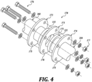
- FIGURE 4 is an exploded view of the low-turbulence connection 170 connecting the supply line 202 to the helical feed dispersing tube 210.
- Fish feed for aquaculture typically comprises small pebbles of feed that may be suspended in a fluid.
- the food pebbles may have a transverse dimension, for example, between 0,3 cm (one-eighth inch) and 3 cm (one inch).
- the feed and transporting fluid are flowed through the supply line 202 to the helical feed dispersing tube 210.
- High turbulence or other interference in the joint or connection to the dispersing tube 210 can cause the fish feed to disintegrate or crumble, which can result in a significant loss of feed during the feeding process.
- Feed is a significant cost in aquaculture, and particularly in off-shore aquaculture, which requires transporting the feed significant distances to the fish pen. Therefore, it is very desirable to minimize the loss of feed.
- the low-turbulence joint 170 comprises a flanged input end 121 on the feed dispersing tube that is sized to abut a corresponding flanged output end 113 on the supply line 202, with a gasket 171 there between.
- the gasket 171 has an aperture 172 that matches the inside diameter of the supply line 202 and the dispersing tube 210 at the joint 170.
- a first annular disc 173 is sized and positioned to abut the flanged output end 113, and a second annular disc 174 is sized and positioned to abut the flanged input end 121.
- the first and second annular discs 173, 174 have corresponding apertures 175 that are sized and positioned to receive attachment hardware, for example, bolts 176 and nuts 177 to urge the annular discs 173, 174 towards each other, accurately positioning and compressing the flanged ends 113, 121 towards each other.
- the gasket 171 also has corresponding apertures 178, so that the gasket 171 is also accurately positioned to not interfere with flow though the joint 170.
Landscapes
- Life Sciences & Earth Sciences (AREA)
- Environmental Sciences (AREA)
- Marine Sciences & Fisheries (AREA)
- Zoology (AREA)
- Animal Husbandry (AREA)
- Biodiversity & Conservation Biology (AREA)
- Farming Of Fish And Shellfish (AREA)
Description
- The seas and other natural water reservoirs have provided an abundant and stable supply of sustenance for millennia. In recent years, however, over-fishing, inefficient harvesting practices, and environmental stressors have resulted in the depletion or decline of certain fish populations in many regions. At the same time, an increasing human population, increasing standards of living, and an increasing awareness of the health benefits of seafood have increased the demand for fish and fish product.
- Advances in aquaculture in general, and fish farming in particular, and improvements in technology have recently been applied to meet world demand for fish product efficiently and at lower costs. Developments in fish farming also reduce the risks associated with over-fishing existing fish populations. In particular, off-shore cultivation systems employing fish cages or fish pens have found some success. Large, submersible fish pens suitable for aquaculture applications are known in the art to aid in the efficient and bio-responsible cultivation of food sources. Fish pens are placed in a natural body of water, such as a lake, river, or ocean, and stocked with young fish or fry, and the fish are fed and maintained until they reach maturity. The fish pens provide a habitat and protection for the fish. Fish pens may be used for freshwater or for saltwater aquaculture.
- Some conventional fish farming systems provide a pen that is anchored to the ocean floor. In one embodiment, a fish pen includes four spar buoys with damper plates coupled to the bottom that dampen the buoy motion caused by wave action. The four spar buoys are typically arranged in a rectangular array with a net fastened to the spar buoys to define a box-like enclosure. Anchor lines extend outwardly and downwardly from each spar buoy to support the nets.
- More recent innovations in fish pens employing a center spar buoy or center cluster of spar buoys are disclosed in
U.S. Patent No. 5,359,962, to Loverich , and inU.S. Patent No. 5,617,813, to Loverich et al . Loverich et al. discloses a mobile pen for raising fish or shellfish having an elongate central vertical spar buoy surrounded by at least one net-supporting rim assembly with continuous netting extending from an upper end of the spar buoy to the rim assembly and thence to a lower, submerged end of the spar buoy. For example, a novel open sea center spar fish pen having an elongate spar buoy, and one or more rim assemblies attached to the spar buoy is disclosed inU.S. Patent No. 9,072,282, to Madsen et al. - A submerged feed disperser system for an open sea fish pen is disclosed herein that increases the effective volume over which feed is delivered inside a fish pen in a submerged state. The feed disperser allows more fish to eat to satiation by reducing competition for feed. The reduced competition for feed encourages consistent fish growth within a population, while reducing aggression during feeding, and reducing the loss or waste of feed pellets during feeding. The feed disperser has also been found to produce an improved coefficient of variation in fish size by allowing less aggressive fish to more easily acquire and consume feed, decreasing fish mortality and improving the feed conversion ratio. The feed disperser has been found to reduce damage to pelletized fish feed during dispersal of the feed.
- Less efficient alternate means for distributing feed within fish pens currently in use employ a small concentrated feed outflow point, typically using a structure with four distribution points arranged in a row and spread over a relatively short distance, for example one meter. In these prior art systems feed is delivered over a small area resulting in intense competition for feed and a highly skewed distribution of feed consumption towards larger, more aggressive fish.
- Other fish feed systems are known in the art.
U.S. Pat. No. 7,743,733, to Harrison et al. , discloses an offshore aquaculture system including a fish feeding apparatus configured to dispense a slurry containing fish feed in streams upwardly and outwardly from a dispenser head at a number of circumferentially spaced outlets at the water surface. -
U.S. Pat. No. 9,655,347, to Troy et al. -
U.S. Pat. No. 9,326,493, to Han et al. -
JP 2003 158949 A - These prior art fish feeding systems do not disperse fish feed throughout the fish enclosure in a manner that discourages competition for food, and encourages a more equitable distribution of food to provide more optimal and consistent feeding.
- The invention provides according to independent claim 1 a submergible fish feed dispersing apparatus configured to deliver feed inside an aquaculture fish pen in a submerged state, the fish feed dispersing apparatus including a flexible helical dispersing tube having an inlet that receives fish feed from a source. A plurality of spaced-apart apertures in the helical dispersing tube disperse the received fish feed. A mounting assembly with two spaced-apart attachment members is fixed to the fish pen with a plurality of elongate members extending between the two spaced-apart attachment members. A number of hanger subassemblies are adjustably supported on the plurality of elongate members. Each hanger subassembly has a proximal end attached to a corresponding one of the elongate members and a distal end with a clamp configured to engage the helical dispersing tube. The mounting assembly is configured to control the pitch of the helical dispersing tube.
- In an embodiment the plurality of apertures are not aligned on the helical feed dispersing tube.
- In an embodiment the plurality of apertures open outwardly away from the helical dispersing tube.
- In an embodiment the two attachment members are configured to be fixed to a spar buoy of the fish pen.
- In an embodiment the helical dispersing tube continuously decreases in elevation such that the plurality of spaced apertures are at different depths.
- In an embodiment a distal end of the helical dispersing tube is an open outlet.
- In an embodiment the helical dispersing tube defines a circular helix.
- In an embodiment each of the hanger subassemblies comprises a first arm that defines the proximal end and the distal end, and further comprising a second arm having a proximal end connected to the corresponding elongate member and a distal end that engages the first arm at a selectable intermediate location on the first arm. For example, the plurality of elongate members may have a plurality of apertures for attaching the proximal end of the first arm and the second arm to a selectable location on the corresponding elongate member.
- In an embodiment the pitch of the helical dispersing tube is determined by the selected location of the hanger assemblies on the corresponding elongate members.
- In an embodiment the plurality of hanger subassemblies comprise at least four hanger subassemblies.
- In an embodiment the plurality of apertures disposed at spaced intervals along the helical dispersing tube comprise at least seven apertures.
- In an embodiment the first and second arms are configured to pivot toward the corresponding elongate member into a folded position when the helical dispersing tube is removed.
- The foregoing embodiments and many of the attendant advantages of this invention will become more readily appreciated as the same become better understood by reference to the following detailed description, when taken in conjunction with the accompanying drawings, wherein:
-
FIGURE 1 is a front view of a vertical spar fish pen having a feed dispersing assembly in accordance with the present invention; -
FIGURE 2A is a perspective view of the fish pen feed dispersing assembly shown inFIGURE 1 ; -
FIGURE 2B is a front view of the fish pen feed dispersing assembly shown inFIGURE 1 ; -
FIGURE 2C is a top plan view of the fish pen feed dispersing assembly shown inFIGURE 1 ; -
FIGURE 3 is a front view of the fish feed attachment assembly shown inFIGURE 2A , with the hanger subassemblies shown in a folded position; and -
FIGURE 4 is an exploded perspective view of a low-turbulence connection for connecting the feed supply line to a helical feed dispersing tube. - A
fish pen 100 with a helicalfeed dispersing assembly 200 in accordance with the present invention is shown inFIGURE 1 . Thefish pen 100 includes an elongatecenter spar buoy 110 that is configured to remain upright in the body of water. Alower rim assembly 130 and anupper rim assembly 140 are horizontally disposed about thespar buoy 110, and are attached to thespar buoy 110 with a cable assembly formed from a system ofcables hawser 133 that is fixed to an object or anchor (not shown) to anchor thefish pen 100. Anenclosure 160, for example a netting assembly, is supported by thecenter spar buoy 110 and therim assemblies fish pen 100 is configured to be movable between a submerged position wherein substantially all of theenclosure 160 is below the waterline, and a surfaced position wherein at least a portion of theenclosure 160 is above the waterline. In other embodiments the center spar fish pens may have more or fewer rim assemblies and different enclosure and/or cabling configurations, as will be apparent to persons of skill in the art. - For example, the
fish pen 100 may be assembled at, and/or towed to, a desired location for raising fish and anchored in place. Thefish pen 100 allows the fish to be raised in, and benefit from, a natural sea environment while also being protected from predators. In some applications, thefish pen 100 is configured to be towed or otherwise repositioned while fully assembled, and with or without a live fish population, for example, to allow the fish pen to be relocated to optimal locations to accommodate seasonal or weather-related changes. - A portion of the
enclosure 160 is illustrated in cutaway to show an exemplary helicalfeed dispersing assembly 200 that is mounted to thespar buoy 110 and connected to afeed supply line 202. Thehelical feed disperser 200 is attached to thecenter spar buoy 110 at a selectable axial location within theenclosure 160, for example, on an upper portion of thespar buoy 110. Afeed supply line 202 provides fish feed to thefeed dispersing assembly 200 from a source of fish feed (not shown) that may be located outside of theenclosure 160. For example, thesupply line 202 may be fixedly attached to thefish pen 100, or may be deployable, for example, comprising a hose from a supply vessel or barge. - The
feed dispersing assembly 200 includes a helicalfeed dispersing tube 210 that is configured to increase the effective volume over which fish feed is delivered inside theenclosure 160. By more effectively distributing the feed among the fish population, a greater percentage of the fish population are able to eat to optimal satiation, and potentially destructive competition between fish for feed is decreased. The more equitable distribution of feed provides for a more uniform and healthy fish population, reduced aggression during feeding, and reduced loss of feed from feed pellets falling through the fish pen. Improving the distribution of the feed also results in improved (i.e., reduced) coefficient of variation (CV) in the fish size. -
FIGURE 2A is a perspective view of thefeed dispersing assembly 200,FIGURE 2B is a front view of the dispersingassembly 200, andFIGURE 2C is a plan view of the dispersingassembly 200. Thefeed dispersing assembly 200 includes thehelical dispersing tube 210 and an attachment orhanger assembly 220, that attaches thehelical dispersing tube 210 to the spar buoy 110 (FIGURE 1 ) and maintains the dispersingtube 210 in a desired configuration. In the current embodiment thehanger assembly 220 is adjustable. According to the invention, the dispersingtube 210 is flexible, such that the pitch (and axial length) of thehelical dispersing tube 210 can be set to provide optimal feed dispersion. Theadjustable hanger assembly 220 is configured to accommodatedifferent dispersing tubes 210 and to accommodate different pitches for anyparticular dispersing tube 210. Although thehelical dispersing tube 210 in this embodiment is shown with a generally constant diameter, right circular helical shape, it is contemplated that in other embodiments the helical shape may be non-circular, for example elliptical or with sinuous sections, and/or the helical shape may have a non-uniform radius, for example a conical or other non-regular helical shape. - The dispersing
tube 210 has aproximal end 208 that is configured to be connected to thefeed supply line 202 with a low-turbulence connection 170, as discussed below and illustrated inFIGURE 4 . The dispersingtube 210 has a plurality of spaced-apart apertures 212 distributed along the length of thetube 210 that provide a plurality of outflow feed streams during use. The size, position and orientation of theapertures 212 may be selected to provide a desired outflow volume and dispersal pattern. In some embodiments a plurality ofinterchangeable dispersing tubes 210 are provided, to allow the user to optimize the fish feeding apparatus to accommodate particular fish food characteristics, fish feeding requirements, and the like. In a current embodiment theapertures 212 are between 2,5 and 12,7 cm (one and five inches) in diameter. Adistal end 214 of the dispersingtube 210 is preferably open and provides an additional feed stream. Thedistal end 214 may include a flow restrictor (not shown) to achieve a desired pressure in the dispersingtube 210 during use. - In a particular embodiment the
helical dispersing tube 210 is an HDPE (high density polyethylene) hose and has a length between 6 and 60 m (twenty and two hundred feet), and an inside diameter between 3 and 15 cm (one and six inches), for example, a constant inside diameter of 8 cm (three inches). In some embodiments the diameter of the dispersingtube 210 may vary along the length of the dispersingtube 210. As fish feed pellets are pumped into thefeed dispersing tube 210 from thesupply line 202, a large percentage of the feed is expelled through theapertures 212 along the length of the dispersingtube 210. - In an exemplary embodiment the
feed dispersing tube 210 is 15 m (fifty feet) long and has a 8 cm (three-inch) inside diameter. Theapertures 212 have a diameter between 2,5 cm (1.0 inches) and 3,8 cm (1.5 inches) and are spaced approximately 2 m (six feet) apart along the length of the dispersingtube 210. In a representative embodiment the aperture 212 size and orientations are as follows: (i) a first aperture 212 is located 15 cm (one-half foot) from the proximal end 208 (measured along the tube 210), has a diameter of 3 cm (1 inch), and is oriented outwardly (from the helical feed dispersing tube 210) and zero degrees from horizontal; (ii) a second aperture 212 is located 2 m (seven feet) from the proximal end 208, has a diameter of 3,8 cm (1.5 inches), and is oriented outwardly and zero degrees from horizontal; (iii) a third aperture 212 is located 4 m (fourteen feet) from the proximal end 208, has a diameter of 3,8 cm (1.5 inches), and is oriented outwardly and upwardly 22.5 degrees from horizontal; (iv) a fourth aperture 212 is located 6 m (twenty-one feet) from the proximal end 208, has a diameter of 3,8 cm (1.5 inches), and is oriented outwardly and upwardly 45 degrees from horizontal; (v) a fifth aperture 212 is located 8 m (twenty-seven feet) from the proximal end 208, has a diameter of 3,8 cm (1.5 inches), and is oriented outwardly and upwardly 45 degrees from horizontal; (vi) a sixth aperture 212 is located 10 m (34 feet) from the proximal end 208, has a diameter of 3,8 cm (1.5 inches), and is oriented outwardly and upwardly 22.5 degrees from horizontal; and (vii) a seventh aperture 212 is located 13 m (forty-four feet) from the proximal end 208, has a diameter of 3,8 cm (1.5 inches), and is oriented outwardly and zero degrees from horizontal. In this embodiment thedistal end 214 of the dispersingtube 210 is open such that a portion of the fish feed is expelled from the open end. - Other embodiments are contemplated and have a different number, size, and distribution of
apertures 212. - Referring still to
FIGURES 2A ,2B , and2C , thehanger assembly 220 includes anupper attachment member 221 and alower attachment member 222. Theattachment members hanger assembly 220 to thespar buoy 110. For example, the upper andlower attachment members lower attachment members attachment members elongate members 223 have a plurality ofapertures 224 spaced along the length of theelongate members 223, some of which receive bolts or other connecting hardware (not shown) for fixing theelongate members 223 to theattachment members - A plurality of
adjustable hanger subassemblies 230 are configured to attach to a corresponding one of theelongate members 223, and to support the dispersingtube 210. Thehanger subassemblies 230 include afirst arm 232 and asecond arm 236. Thefirst arm 232 has a proximal end that attaches to the correspondingelongate member 223 through a selectable one of theapertures 224 and a distal end having atube clamp 234 that is configured to engage the dispersingtube 210. A plurality ofslots 233 are provided along a distal portion of thefirst arms 232. Thesecond arm 236 of eachhanger subassembly 230 has a proximal end that attaches to a corresponding one of theelongate members 223 through a selectable one of theapertures 224, and a distal end that includes a connectingplate 235 configured to slidably engage a selectable one of theslots 233 of the correspondingfirst arm 232. An attachment member, for example a locking pin, bolt, shackle, cable tie, or the like (not shown), may be provided to extend through an aperture in the connectingplate 235 to lock thesecond arm 236 to the selected location of thefirst arm 232. - It will be appreciated from
FIGURES 2A-2C and the above description that thehanger subassemblies 230 allow great flexibility in positioning theclamps 234 that engage the dispersingtube 210, for example, allowing the pitch of thehelical dispersing tube 210 to be selected or adjusted for optimal feed dispersion. - In this embodiment the dispersing tube clamps 234 are quick-release clamps, for example, clam shell clamps comprising separable left and right portions, as are well known in the art. The quick-release clamps 234 facilitate removing and replacing the dispersing
tube 210, for example for cleaning or maintenance, to allow the user to installdifferent dispersing tubes 210 as discussed above, or to allow theattachment subassemblies 230 to be moved to a folded position, for example, during harvesting or other fish tending operations. - As shown in
FIGURE 3 , thehanger subassemblies 230 may be configured in a folded position when the dispersingtube 210 is removed by disconnecting thesecond arm 236 from the correspondingfirst arm 232 for each of thehanger subassemblies 230, and pivoting thearms foldable hanger subassemblies 230 are advantageous, for example, to reduce the size of thehanger assembly 220 during harvesting operations, and the like. - Although this disclosed embodiment has an attachment assembly with four
hanger subassemblies 230, it is contemplated that other embodiments may have more orfewer hanger subassemblies 230. In some embodiments the helicalfeed dispersing tube 210 may be longer than is shown in the figures, for example, extending 360 degrees, 540 degrees, 720 degrees, or more, around thespar buoy 110. -
FIGURE 4 is an exploded view of the low-turbulence connection 170 connecting thesupply line 202 to the helicalfeed dispersing tube 210. Fish feed for aquaculture typically comprises small pebbles of feed that may be suspended in a fluid. The food pebbles may have a transverse dimension, for example, between 0,3 cm (one-eighth inch) and 3 cm (one inch). The feed and transporting fluid are flowed through thesupply line 202 to the helicalfeed dispersing tube 210. High turbulence or other interference in the joint or connection to the dispersingtube 210 can cause the fish feed to disintegrate or crumble, which can result in a significant loss of feed during the feeding process. Feed is a significant cost in aquaculture, and particularly in off-shore aquaculture, which requires transporting the feed significant distances to the fish pen. Therefore, it is very desirable to minimize the loss of feed. - The low-
turbulence joint 170 comprises aflanged input end 121 on the feed dispersing tube that is sized to abut a correspondingflanged output end 113 on thesupply line 202, with agasket 171 there between. Thegasket 171 has anaperture 172 that matches the inside diameter of thesupply line 202 and the dispersingtube 210 at the joint 170. - A first
annular disc 173 is sized and positioned to abut theflanged output end 113, and a secondannular disc 174 is sized and positioned to abut theflanged input end 121. The first and secondannular discs corresponding apertures 175 that are sized and positioned to receive attachment hardware, for example,bolts 176 andnuts 177 to urge theannular discs gasket 171 also has correspondingapertures 178, so that thegasket 171 is also accurately positioned to not interfere with flow though the joint 170.
Claims (13)
- A submergible fish feed dispersing apparatus (200) configured to deliver feed inside an aquaculture fish pen (100) in a submerged state, the fish feed dispersing apparatus comprising:a flexible helical dispersing tube (210) having an inlet end (208) configured to receive fish feed from a source of fish feed and a plurality of apertures (212) disposed at spaced intervals along the helical dispersing tube; anda mounting assembly (220) having two spaced-apart attachment members (221, 222) configured to be fixed to the fish pen, a plurality of elongate members (223) attached to and extending between the two attachment members, and a plurality of hanger subassemblies (230), each hanger subassembly having a proximal end attached to a corresponding one of the plurality of elongate members and a distal end comprising a clamp (234) configured to engage the helical dispersing tube, the mounting assembly being configured to control the pitch of the helical dispersing tube.
- The fish feed dispersing apparatus of Claim 1, wherein the plurality of apertures are not aligned on the helical feed dispersing tube.
- The fish feed dispersing apparatus of Claim 1, wherein the plurality of apertures open outwardly away from the helical dispersing tube.
- The fish feed dispersing apparatus of Claim 1, wherein the two attachment members are configured to be fixed to a spar buoy (110) of the fish pen.
- The fish feed dispersing apparatus of Claim 4, wherein when the fish feed dispersing apparatus is fixed to the spar buoy, the helical dispersing tube continuously decreases in elevation such that the plurality of spaced apertures are at different depths.
- The fish feed dispersing apparatus of Claim 4, wherein a distal end (214) of the helical dispersing tube is an open outlet.
- The fish feed dispersing apparatus of Claim 4, wherein the helical dispersing tube defines a circular helix.
- The fish feed dispersing apparatus of Claim 4, wherein each of the hanger subassemblies comprises a first arm (232) that defines the proximal end and the distal end, and further comprising a second arm (236) having a proximal end connected to the corresponding elongate member and a distal end that engages the first arm at a selectable intermediate location on the first arm.
- The fish feed dispersing apparatus of Claim 8, wherein the plurality of elongate members each comprises a plurality of apertures (224) for attaching the proximal end of the first arm and the second arm to a selectable location on the corresponding elongate member.
- The fish feed dispersing apparatus of Claim 9, wherein the pitch of the helical dispersing tube is determined by the selected location of the hanger subassemblies on the corresponding elongate members.
- The fish feed dispersing apparatus of Claim 1, wherein the plurality of hanger subassemblies comprise at least four hanger subassemblies.
- The fish feed dispersing apparatus of Claim 1, wherein the plurality of apertures disposed at spaced intervals along the helical dispersing tube comprise at least seven apertures.
- The fish feed dispersing apparatus of Claim 8, wherein the first and second arms are configured to pivot toward the corresponding elongate member into a folded position when the helical dispersing tube is removed.
Priority Applications (1)
| Application Number | Priority Date | Filing Date | Title |
|---|---|---|---|
| HRP20241241TT HRP20241241T1 (en) | 2017-11-22 | 2018-11-13 | Submerged feed disperser for aquaculture system |
Applications Claiming Priority (2)
| Application Number | Priority Date | Filing Date | Title |
|---|---|---|---|
| US201762590082P | 2017-11-22 | 2017-11-22 | |
| PCT/US2018/060601 WO2019103867A1 (en) | 2017-11-22 | 2018-11-13 | Submerged feed disperser for aquaculture system |
Publications (3)
| Publication Number | Publication Date |
|---|---|
| EP3713404A1 EP3713404A1 (en) | 2020-09-30 |
| EP3713404A4 EP3713404A4 (en) | 2021-08-11 |
| EP3713404B1 true EP3713404B1 (en) | 2024-08-21 |
Family
ID=66534367
Family Applications (1)
| Application Number | Title | Priority Date | Filing Date |
|---|---|---|---|
| EP18881582.3A Active EP3713404B1 (en) | 2017-11-22 | 2018-11-13 | Submerged feed disperser for aquaculture system |
Country Status (11)
| Country | Link |
|---|---|
| US (1) | US10973211B2 (en) |
| EP (1) | EP3713404B1 (en) |
| JP (1) | JP7152486B2 (en) |
| AU (1) | AU2018371718B2 (en) |
| CA (1) | CA3081091A1 (en) |
| DK (1) | DK3713404T3 (en) |
| ES (1) | ES2986919T3 (en) |
| HR (1) | HRP20241241T1 (en) |
| MX (1) | MX2020004676A (en) |
| PT (1) | PT3713404T (en) |
| WO (1) | WO2019103867A1 (en) |
Families Citing this family (11)
| Publication number | Priority date | Publication date | Assignee | Title |
|---|---|---|---|---|
| GB2602753B (en) * | 2017-04-21 | 2023-01-18 | Viewpoint As | Fish pen system with compensation for wave motion |
| US10599922B2 (en) * | 2018-01-25 | 2020-03-24 | X Development Llc | Fish biomass, shape, and size determination |
| US12396441B2 (en) * | 2018-02-12 | 2025-08-26 | David Fries | Biomimetic sentinel reef structures for optical sensing and communications |
| USD891707S1 (en) * | 2018-11-13 | 2020-07-28 | InnovaSea Systems, Inc. | Attachment structure for a fish pen feed disperser |
| CN112931346B (en) * | 2021-03-15 | 2023-01-31 | 潍坊新力蒙水产技术有限公司 | A kind of attachment base for aquaculture |
| US12075735B2 (en) * | 2021-06-16 | 2024-09-03 | Taerra Systems, Inc. | Kelp growth apparatus and method for kelp harvesting |
| CN113728955B (en) * | 2021-08-31 | 2023-05-05 | 山东惠民宏昌化纤绳网有限公司 | Net cage for marine culture |
| CN114568369B (en) * | 2022-03-15 | 2023-01-31 | 肥东县水产养殖技术服务中心 | Aquatic feed feeding machine with mobile aeration and oxygenation functions |
| US12575517B1 (en) * | 2023-06-29 | 2026-03-17 | Clifford A. Goudey | Variable-displacement spar buoy apparatus for macroalgae farming |
| JP7660644B1 (en) | 2023-10-27 | 2025-04-11 | マルハニチロ株式会社 | Feeding device and feeding vessel |
| CN117678556B (en) * | 2024-01-16 | 2026-05-01 | 通威农业发展有限公司 | Uniform feeding device for penaeus vannamei cultivation |
Family Cites Families (27)
| Publication number | Priority date | Publication date | Assignee | Title |
|---|---|---|---|---|
| JPS5444799U (en) * | 1977-09-02 | 1979-03-28 | ||
| JPS5611733A (en) * | 1979-07-06 | 1981-02-05 | Kumagai Gumi Co Ltd | Setting of floated fish bank |
| US4373286A (en) * | 1980-10-16 | 1983-02-15 | Robison Thomas E | Reaction gill net |
| SE426536B (en) * | 1981-06-12 | 1983-01-31 | Gunnar Wensman | KIT FOR FEEDING ANIMALS, PREFERRED FISH, WHERE FEED BY AN AIR FLOW AND THROUGH A FEED ORGAN ORGANIZED IN A LINE AND WHERE THE FEED IS TRANSPORTED TO ONE OR MULTIPLE FEEDING STATION - AND ALSO |
| US4638588A (en) * | 1985-01-07 | 1987-01-27 | Abadie Carole R | Fish attracting device |
| JPS646867U (en) * | 1987-06-30 | 1989-01-13 | ||
| US5299530A (en) * | 1992-07-17 | 1994-04-05 | Occidental Research Corporation | Submergible fish cage |
| CA2108830A1 (en) | 1992-10-29 | 1994-04-29 | Ocean Spar Technologies, L.L.C. | Center-spar fish pen |
| JPH082224B2 (en) * | 1993-05-20 | 1996-01-17 | 政太郎 佐藤 | Underwater feeding device |
| US5617813A (en) * | 1995-03-31 | 1997-04-08 | Ocean Spar Technologies, Llc | Anchorable mobile spar and ring fish pen |
| US5628279A (en) * | 1995-05-01 | 1997-05-13 | Bones, Iv; John W. | Fish cage |
| US5970917A (en) * | 1998-02-27 | 1999-10-26 | Keith, Jr.; Richard W. | Marine aquaculture apparatus |
| JP3887215B2 (en) | 2001-11-27 | 2007-02-28 | 株式会社陸上養殖工学研究所 | Aquaculture feeding device |
| CA2469601A1 (en) | 2004-06-02 | 2005-12-02 | Jeffrey Harrison | An off-shore aquaculture system |
| US7284501B2 (en) | 2004-10-29 | 2007-10-23 | Ocean Farm Technologies, Inc. | Containment pens for finfish aquaculture |
| AU2006236485B2 (en) | 2005-04-14 | 2013-01-31 | Ocean Farm Technologies, Inc. | Finfish containment pens and polyhedral structures |
| JP5408837B2 (en) | 2006-06-16 | 2014-02-05 | ブリヂストンフローテック株式会社 | Water quality improvement structure |
| US9655347B2 (en) | 2006-10-10 | 2017-05-23 | William A Spencer, Jr. | Automated open ocean fish farm structures and systems for open ocean fish farming |
| US8028660B2 (en) * | 2006-10-10 | 2011-10-04 | Hawaii Oceanic Technology, Inc. | Automated positioning and submersible open ocean platform |
| KR200454434Y1 (en) * | 2007-07-04 | 2011-07-04 | 김동주 | Feeding device for deep sea aquaculture |
| US8117992B2 (en) * | 2007-08-22 | 2012-02-21 | Aqua Culture Joint Venture | Aquatic farming systems |
| HRP20170109T1 (en) | 2010-12-29 | 2017-04-07 | Oceanspar, Inc | Center spar fish pen and method for retaining fish in open water |
| KR101024386B1 (en) | 2011-01-20 | 2011-03-23 | 엔엔티시스템즈(주) | Automatic feed system for cage farms |
| KR101064806B1 (en) * | 2011-03-21 | 2011-09-14 | 전라남도 | Tidal Flat Ecosystem with Feeding Organisms |
| CL2014002761A1 (en) * | 2014-10-15 | 2014-11-14 | Marcelo Pavez Vasquez Claudio | Double cone tubular device, free of energy supply, which allows the delivery and conduction of pelletized fish feed in homogeneous rations to two or more disposal points submerged in the water column of an interior area of a fish culture cage; Installation method of fish feed drive device. |
| NO338945B1 (en) * | 2015-02-24 | 2016-11-07 | Næroeysund Aquaservice As | Feeding device for fish feed |
| ES2959226T3 (en) | 2016-02-23 | 2024-02-21 | Innovasea Systems Inc | Aquaculture Fishing Pen with Mortality Trap |
-
2018
- 2018-11-13 AU AU2018371718A patent/AU2018371718B2/en not_active Ceased
- 2018-11-13 US US16/189,927 patent/US10973211B2/en active Active
- 2018-11-13 ES ES18881582T patent/ES2986919T3/en active Active
- 2018-11-13 CA CA3081091A patent/CA3081091A1/en active Pending
- 2018-11-13 HR HRP20241241TT patent/HRP20241241T1/en unknown
- 2018-11-13 DK DK18881582.3T patent/DK3713404T3/en active
- 2018-11-13 WO PCT/US2018/060601 patent/WO2019103867A1/en not_active Ceased
- 2018-11-13 PT PT188815823T patent/PT3713404T/en unknown
- 2018-11-13 EP EP18881582.3A patent/EP3713404B1/en active Active
- 2018-11-13 MX MX2020004676A patent/MX2020004676A/en unknown
- 2018-11-13 JP JP2020528139A patent/JP7152486B2/en not_active Expired - Fee Related
Also Published As
| Publication number | Publication date |
|---|---|
| EP3713404A4 (en) | 2021-08-11 |
| WO2019103867A1 (en) | 2019-05-31 |
| ES2986919T3 (en) | 2024-11-13 |
| MX2020004676A (en) | 2020-08-13 |
| DK3713404T3 (en) | 2024-09-16 |
| AU2018371718A1 (en) | 2020-06-11 |
| US10973211B2 (en) | 2021-04-13 |
| CA3081091A1 (en) | 2019-05-31 |
| PT3713404T (en) | 2024-09-09 |
| HRP20241241T1 (en) | 2024-12-06 |
| AU2018371718B2 (en) | 2024-06-13 |
| EP3713404A1 (en) | 2020-09-30 |
| JP7152486B2 (en) | 2022-10-12 |
| JP2021503900A (en) | 2021-02-15 |
| US20190150410A1 (en) | 2019-05-23 |
Similar Documents
| Publication | Publication Date | Title |
|---|---|---|
| AU2018371718B2 (en) | Submerged feed disperser for aquaculture system | |
| EP3687286B1 (en) | Semi-submersible spar-type offshore fish farm with detachable and pivotable coupling assembly | |
| CA2216754C (en) | Anchorable mobile spar and ring fish pen | |
| US20190159434A1 (en) | Device for Rearing Aquaculture Animals At Sea | |
| US9681645B2 (en) | Structure for attracting and accumulating aquatic organisms | |
| CN1036122A (en) | Ocean fish farm | |
| JP2019104420A (en) | Offshore wind power generation facility | |
| JP2020520651A (en) | Feeding device for closed enclosures and method of food distribution in closed enclosures | |
| JP2021528993A (en) | Open ocean cage | |
| JP2019104419A (en) | Offshore wind farm | |
| KR101642777B1 (en) | A Shelter For Abalone Culture | |
| CN110973030B (en) | Fully-submerged array type breeding equipment | |
| KR20140009659A (en) | The cultivating device for shellfishes | |
| CN217905827U (en) | Novel multi-functional artifical fish nest of combination formula | |
| CN109220890A (en) | A kind of floating type artificial marine habitat in lake with bird henroost | |
| CN120188758B (en) | Deep-open sea large-scale aquaculture net case based on automatic function of throwing something and feeding | |
| US10638729B2 (en) | Fishermen's island for growing 10,000 tons of fish and seafood in water-filled ring-tube fishery | |
| CN107145170A (en) | A kind of Level monitor used for aquiculture | |
| CN217428999U (en) | Pond culture micropterus salmoides bait platform device | |
| CN110663594A (en) | A method of fish enhancement and fishing for ecological cycle fishery | |
| CN215836557U (en) | Floating type crayfish breeding cage and breeding platform | |
| CN208639339U (en) | Feedstuff feeding floating platform | |
| CN103734059B (en) | Seed device is broadcast at the bottom of a kind of artificial fish shelter | |
| Anuraj et al. | Sea Cage Farming | |
| Suresh Babu et al. | Sea cage farming |
Legal Events
| Date | Code | Title | Description |
|---|---|---|---|
| REG | Reference to a national code |
Ref country code: HR Ref legal event code: TUEP Ref document number: P20241241T Country of ref document: HR |
|
| STAA | Information on the status of an ep patent application or granted ep patent |
Free format text: STATUS: THE INTERNATIONAL PUBLICATION HAS BEEN MADE |
|
| PUAI | Public reference made under article 153(3) epc to a published international application that has entered the european phase |
Free format text: ORIGINAL CODE: 0009012 |
|
| STAA | Information on the status of an ep patent application or granted ep patent |
Free format text: STATUS: REQUEST FOR EXAMINATION WAS MADE |
|
| 17P | Request for examination filed |
Effective date: 20200430 |
|
| AK | Designated contracting states |
Kind code of ref document: A1 Designated state(s): AL AT BE BG CH CY CZ DE DK EE ES FI FR GB GR HR HU IE IS IT LI LT LU LV MC MK MT NL NO PL PT RO RS SE SI SK SM TR |
|
| AX | Request for extension of the european patent |
Extension state: BA ME |
|
| DAV | Request for validation of the european patent (deleted) | ||
| DAX | Request for extension of the european patent (deleted) | ||
| A4 | Supplementary search report drawn up and despatched |
Effective date: 20210708 |
|
| RIC1 | Information provided on ipc code assigned before grant |
Ipc: A01K 61/80 20170101AFI20210702BHEP Ipc: A01K 61/60 20170101ALI20210702BHEP |
|
| GRAP | Despatch of communication of intention to grant a patent |
Free format text: ORIGINAL CODE: EPIDOSNIGR1 |
|
| STAA | Information on the status of an ep patent application or granted ep patent |
Free format text: STATUS: GRANT OF PATENT IS INTENDED |
|
| RIC1 | Information provided on ipc code assigned before grant |
Ipc: A01K 61/60 20170101ALI20240228BHEP Ipc: A01K 61/80 20170101AFI20240228BHEP |
|
| INTG | Intention to grant announced |
Effective date: 20240313 |
|
| GRAS | Grant fee paid |
Free format text: ORIGINAL CODE: EPIDOSNIGR3 |
|
| GRAA | (expected) grant |
Free format text: ORIGINAL CODE: 0009210 |
|
| STAA | Information on the status of an ep patent application or granted ep patent |
Free format text: STATUS: THE PATENT HAS BEEN GRANTED |
|
| AK | Designated contracting states |
Kind code of ref document: B1 Designated state(s): AL AT BE BG CH CY CZ DE DK EE ES FI FR GB GR HR HU IE IS IT LI LT LU LV MC MK MT NL NO PL PT RO RS SE SI SK SM TR |
|
| P01 | Opt-out of the competence of the unified patent court (upc) registered |
Free format text: CASE NUMBER: APP_41211/2024 Effective date: 20240711 |
|
| REG | Reference to a national code |
Ref country code: GB Ref legal event code: FG4D |
|
| REG | Reference to a national code |
Ref country code: CH Ref legal event code: EP |
|
| REG | Reference to a national code |
Ref country code: DE Ref legal event code: R096 Ref document number: 602018073479 Country of ref document: DE |
|
| REG | Reference to a national code |
Ref country code: PT Ref legal event code: SC4A Ref document number: 3713404 Country of ref document: PT Date of ref document: 20240909 Kind code of ref document: T Free format text: AVAILABILITY OF NATIONAL TRANSLATION Effective date: 20240903 |
|
| REG | Reference to a national code |
Ref country code: IE Ref legal event code: FG4D |
|
| REG | Reference to a national code |
Ref country code: DK Ref legal event code: T3 Effective date: 20240910 |
|
| REG | Reference to a national code |
Ref country code: SE Ref legal event code: TRGR |
|
| REG | Reference to a national code |
Ref country code: ES Ref legal event code: FG2A Ref document number: 2986919 Country of ref document: ES Kind code of ref document: T3 Effective date: 20241113 |
|
| REG | Reference to a national code |
Ref country code: GR Ref legal event code: EP Ref document number: 20240402134 Country of ref document: GR Effective date: 20241111 |
|
| REG | Reference to a national code |
Ref country code: HR Ref legal event code: T1PR Ref document number: P20241241 Country of ref document: HR |
|
| REG | Reference to a national code |
Ref country code: LT Ref legal event code: MG9D |
|
| PGFP | Annual fee paid to national office [announced via postgrant information from national office to epo] |
Ref country code: PT Payment date: 20241025 Year of fee payment: 7 |
|
| REG | Reference to a national code |
Ref country code: HR Ref legal event code: ODRP Ref document number: P20241241 Country of ref document: HR Payment date: 20241119 Year of fee payment: 7 |
|
| REG | Reference to a national code |
Ref country code: NL Ref legal event code: MP Effective date: 20240821 |
|
| PGFP | Annual fee paid to national office [announced via postgrant information from national office to epo] |
Ref country code: DE Payment date: 20241128 Year of fee payment: 7 |
|
| PGFP | Annual fee paid to national office [announced via postgrant information from national office to epo] |
Ref country code: NO Payment date: 20241119 Year of fee payment: 7 |
|
| PGFP | Annual fee paid to national office [announced via postgrant information from national office to epo] |
Ref country code: DK Payment date: 20241126 Year of fee payment: 7 |
|
| REG | Reference to a national code |
Ref country code: AT Ref legal event code: MK05 Ref document number: 1714549 Country of ref document: AT Kind code of ref document: T Effective date: 20240821 |
|
| PG25 | Lapsed in a contracting state [announced via postgrant information from national office to epo] |
Ref country code: FI Free format text: LAPSE BECAUSE OF FAILURE TO SUBMIT A TRANSLATION OF THE DESCRIPTION OR TO PAY THE FEE WITHIN THE PRESCRIBED TIME-LIMIT Effective date: 20240821 Ref country code: NL Free format text: LAPSE BECAUSE OF FAILURE TO SUBMIT A TRANSLATION OF THE DESCRIPTION OR TO PAY THE FEE WITHIN THE PRESCRIBED TIME-LIMIT Effective date: 20240821 Ref country code: PL Free format text: LAPSE BECAUSE OF FAILURE TO SUBMIT A TRANSLATION OF THE DESCRIPTION OR TO PAY THE FEE WITHIN THE PRESCRIBED TIME-LIMIT Effective date: 20240821 |
|
| PGFP | Annual fee paid to national office [announced via postgrant information from national office to epo] |
Ref country code: GR Payment date: 20241122 Year of fee payment: 7 |
|
| PGFP | Annual fee paid to national office [announced via postgrant information from national office to epo] |
Ref country code: GB Payment date: 20241126 Year of fee payment: 7 |
|
| PG25 | Lapsed in a contracting state [announced via postgrant information from national office to epo] |
Ref country code: BG Free format text: LAPSE BECAUSE OF FAILURE TO SUBMIT A TRANSLATION OF THE DESCRIPTION OR TO PAY THE FEE WITHIN THE PRESCRIBED TIME-LIMIT Effective date: 20240821 |
|
| PG25 | Lapsed in a contracting state [announced via postgrant information from national office to epo] |
Ref country code: LV Free format text: LAPSE BECAUSE OF FAILURE TO SUBMIT A TRANSLATION OF THE DESCRIPTION OR TO PAY THE FEE WITHIN THE PRESCRIBED TIME-LIMIT Effective date: 20240821 |
|
| PG25 | Lapsed in a contracting state [announced via postgrant information from national office to epo] |
Ref country code: AT Free format text: LAPSE BECAUSE OF FAILURE TO SUBMIT A TRANSLATION OF THE DESCRIPTION OR TO PAY THE FEE WITHIN THE PRESCRIBED TIME-LIMIT Effective date: 20240821 |
|
| PGFP | Annual fee paid to national office [announced via postgrant information from national office to epo] |
Ref country code: IS Payment date: 20241125 Year of fee payment: 7 Ref country code: FR Payment date: 20241016 Year of fee payment: 7 |
|
| PGFP | Annual fee paid to national office [announced via postgrant information from national office to epo] |
Ref country code: HR Payment date: 20241119 Year of fee payment: 7 Ref country code: IE Payment date: 20241119 Year of fee payment: 7 |
|
| PG25 | Lapsed in a contracting state [announced via postgrant information from national office to epo] |
Ref country code: RS Free format text: LAPSE BECAUSE OF FAILURE TO SUBMIT A TRANSLATION OF THE DESCRIPTION OR TO PAY THE FEE WITHIN THE PRESCRIBED TIME-LIMIT Effective date: 20241121 |
|
| PGFP | Annual fee paid to national office [announced via postgrant information from national office to epo] |
Ref country code: IT Payment date: 20241125 Year of fee payment: 7 Ref country code: ES Payment date: 20241218 Year of fee payment: 7 |
|
| PGFP | Annual fee paid to national office [announced via postgrant information from national office to epo] |
Ref country code: SE Payment date: 20241126 Year of fee payment: 7 |
|
| PG25 | Lapsed in a contracting state [announced via postgrant information from national office to epo] |
Ref country code: RS Free format text: LAPSE BECAUSE OF FAILURE TO SUBMIT A TRANSLATION OF THE DESCRIPTION OR TO PAY THE FEE WITHIN THE PRESCRIBED TIME-LIMIT Effective date: 20241121 Ref country code: PL Free format text: LAPSE BECAUSE OF FAILURE TO SUBMIT A TRANSLATION OF THE DESCRIPTION OR TO PAY THE FEE WITHIN THE PRESCRIBED TIME-LIMIT Effective date: 20240821 Ref country code: NL Free format text: LAPSE BECAUSE OF FAILURE TO SUBMIT A TRANSLATION OF THE DESCRIPTION OR TO PAY THE FEE WITHIN THE PRESCRIBED TIME-LIMIT Effective date: 20240821 Ref country code: LV Free format text: LAPSE BECAUSE OF FAILURE TO SUBMIT A TRANSLATION OF THE DESCRIPTION OR TO PAY THE FEE WITHIN THE PRESCRIBED TIME-LIMIT Effective date: 20240821 Ref country code: FI Free format text: LAPSE BECAUSE OF FAILURE TO SUBMIT A TRANSLATION OF THE DESCRIPTION OR TO PAY THE FEE WITHIN THE PRESCRIBED TIME-LIMIT Effective date: 20240821 Ref country code: BG Free format text: LAPSE BECAUSE OF FAILURE TO SUBMIT A TRANSLATION OF THE DESCRIPTION OR TO PAY THE FEE WITHIN THE PRESCRIBED TIME-LIMIT Effective date: 20240821 Ref country code: AT Free format text: LAPSE BECAUSE OF FAILURE TO SUBMIT A TRANSLATION OF THE DESCRIPTION OR TO PAY THE FEE WITHIN THE PRESCRIBED TIME-LIMIT Effective date: 20240821 |
|
| PGFP | Annual fee paid to national office [announced via postgrant information from national office to epo] |
Ref country code: TR Payment date: 20241025 Year of fee payment: 7 |
|
| PG25 | Lapsed in a contracting state [announced via postgrant information from national office to epo] |
Ref country code: SM Free format text: LAPSE BECAUSE OF FAILURE TO SUBMIT A TRANSLATION OF THE DESCRIPTION OR TO PAY THE FEE WITHIN THE PRESCRIBED TIME-LIMIT Effective date: 20240821 Ref country code: RO Free format text: LAPSE BECAUSE OF FAILURE TO SUBMIT A TRANSLATION OF THE DESCRIPTION OR TO PAY THE FEE WITHIN THE PRESCRIBED TIME-LIMIT Effective date: 20240821 |
|
| PG25 | Lapsed in a contracting state [announced via postgrant information from national office to epo] |
Ref country code: EE Free format text: LAPSE BECAUSE OF FAILURE TO SUBMIT A TRANSLATION OF THE DESCRIPTION OR TO PAY THE FEE WITHIN THE PRESCRIBED TIME-LIMIT Effective date: 20240821 |
|
| PG25 | Lapsed in a contracting state [announced via postgrant information from national office to epo] |
Ref country code: CZ Free format text: LAPSE BECAUSE OF FAILURE TO SUBMIT A TRANSLATION OF THE DESCRIPTION OR TO PAY THE FEE WITHIN THE PRESCRIBED TIME-LIMIT Effective date: 20240821 |
|
| PG25 | Lapsed in a contracting state [announced via postgrant information from national office to epo] |
Ref country code: SK Free format text: LAPSE BECAUSE OF FAILURE TO SUBMIT A TRANSLATION OF THE DESCRIPTION OR TO PAY THE FEE WITHIN THE PRESCRIBED TIME-LIMIT Effective date: 20240821 |
|
| REG | Reference to a national code |
Ref country code: DE Ref legal event code: R097 Ref document number: 602018073479 Country of ref document: DE |
|
| PLBE | No opposition filed within time limit |
Free format text: ORIGINAL CODE: 0009261 |
|
| STAA | Information on the status of an ep patent application or granted ep patent |
Free format text: STATUS: NO OPPOSITION FILED WITHIN TIME LIMIT |
|
| REG | Reference to a national code |
Ref country code: CH Ref legal event code: PL |
|
| PG25 | Lapsed in a contracting state [announced via postgrant information from national office to epo] |
Ref country code: MC Free format text: LAPSE BECAUSE OF FAILURE TO SUBMIT A TRANSLATION OF THE DESCRIPTION OR TO PAY THE FEE WITHIN THE PRESCRIBED TIME-LIMIT Effective date: 20240821 |
|
| PG25 | Lapsed in a contracting state [announced via postgrant information from national office to epo] |
Ref country code: LU Free format text: LAPSE BECAUSE OF NON-PAYMENT OF DUE FEES Effective date: 20241113 |
|
| REG | Reference to a national code |
Ref country code: CH Ref legal event code: PL |
|
| PG25 | Lapsed in a contracting state [announced via postgrant information from national office to epo] |
Ref country code: CH Free format text: LAPSE BECAUSE OF NON-PAYMENT OF DUE FEES Effective date: 20241130 |
|
| PGFP | Annual fee paid to national office [announced via postgrant information from national office to epo] |
Ref country code: CY Payment date: 20241108 Year of fee payment: 7 |
|
| 26N | No opposition filed |
Effective date: 20250522 |
|
| REG | Reference to a national code |
Ref country code: BE Ref legal event code: MM Effective date: 20241130 |
|
| PG25 | Lapsed in a contracting state [announced via postgrant information from national office to epo] |
Ref country code: BE Free format text: LAPSE BECAUSE OF NON-PAYMENT OF DUE FEES Effective date: 20241130 |
|
| PG25 | Lapsed in a contracting state [announced via postgrant information from national office to epo] |
Ref country code: HU Free format text: LAPSE BECAUSE OF FAILURE TO SUBMIT A TRANSLATION OF THE DESCRIPTION OR TO PAY THE FEE WITHIN THE PRESCRIBED TIME-LIMIT; INVALID AB INITIO Effective date: 20181113 |
|
| REG | Reference to a national code |
Ref country code: HR Ref legal event code: PBON Ref document number: P20241241 Country of ref document: HR Effective date: 20251113 |
|
| REG | Reference to a national code |
Ref country code: DE Ref legal event code: R119 Ref document number: 602018073479 Country of ref document: DE |
|
| PG25 | Lapsed in a contracting state [announced via postgrant information from national office to epo] |
Ref country code: SI Free format text: LAPSE BECAUSE OF FAILURE TO SUBMIT A TRANSLATION OF THE DESCRIPTION OR TO PAY THE FEE WITHIN THE PRESCRIBED TIME-LIMIT Effective date: 20240821 |
|
| REG | Reference to a national code |
Ref country code: DK Ref legal event code: EBP Effective date: 20251130 |
|
| PG25 | Lapsed in a contracting state [announced via postgrant information from national office to epo] |
Ref country code: LT Free format text: LAPSE BECAUSE OF FAILURE TO SUBMIT A TRANSLATION OF THE DESCRIPTION OR TO PAY THE FEE WITHIN THE PRESCRIBED TIME-LIMIT Effective date: 20240821 |
|
| PG25 | Lapsed in a contracting state [announced via postgrant information from national office to epo] |
Ref country code: PT Free format text: LAPSE BECAUSE OF FAILURE TO SUBMIT A TRANSLATION OF THE DESCRIPTION OR TO PAY THE FEE WITHIN THE PRESCRIBED TIME-LIMIT Effective date: 20251113 Ref country code: GR Free format text: LAPSE BECAUSE OF NON-PAYMENT OF DUE FEES Effective date: 20260608 |
|
| PG25 | Lapsed in a contracting state [announced via postgrant information from national office to epo] |
Ref country code: NO Free format text: LAPSE BECAUSE OF NON-PAYMENT OF DUE FEES Effective date: 20251130 |
|
| PG25 | Lapsed in a contracting state [announced via postgrant information from national office to epo] |
Ref country code: SE Free format text: LAPSE BECAUSE OF NON-PAYMENT OF DUE FEES Effective date: 20251114 |
|
| PG25 | Lapsed in a contracting state [announced via postgrant information from national office to epo] |
Ref country code: CY Free format text: LAPSE BECAUSE OF NON-PAYMENT OF DUE FEES Effective date: 20251114 Ref country code: HR Free format text: LAPSE BECAUSE OF NON-PAYMENT OF DUE FEES Effective date: 20251113 |
|
| PG25 | Lapsed in a contracting state [announced via postgrant information from national office to epo] |
Ref country code: PT Free format text: LAPSE BECAUSE OF NON-PAYMENT OF DUE FEES Effective date: 20260513 |
|
| PG25 | Lapsed in a contracting state [announced via postgrant information from national office to epo] |
Ref country code: IS Free format text: LAPSE BECAUSE OF NON-PAYMENT OF DUE FEES Effective date: 20260602 |