EP3713031A1 - Réseau de bord d'un véhicule et méthode pour concevoir une ligne électrique d'un réseau de bord - Google Patents
Réseau de bord d'un véhicule et méthode pour concevoir une ligne électrique d'un réseau de bord Download PDFInfo
- Publication number
- EP3713031A1 EP3713031A1 EP20020036.8A EP20020036A EP3713031A1 EP 3713031 A1 EP3713031 A1 EP 3713031A1 EP 20020036 A EP20020036 A EP 20020036A EP 3713031 A1 EP3713031 A1 EP 3713031A1
- Authority
- EP
- European Patent Office
- Prior art keywords
- electrical
- load
- board network
- line
- temperature
- Prior art date
- Legal status (The legal status is an assumption and is not a legal conclusion. Google has not performed a legal analysis and makes no representation as to the accuracy of the status listed.)
- Pending
Links
Images

Classifications
-
- H—ELECTRICITY
- H02—GENERATION; CONVERSION OR DISTRIBUTION OF ELECTRIC POWER
- H02J—CIRCUIT ARRANGEMENTS OR SYSTEMS FOR SUPPLYING OR DISTRIBUTING ELECTRIC POWER; SYSTEMS FOR STORING ELECTRIC ENERGY
- H02J1/00—Circuit arrangements for dc mains or dc distribution networks
- H02J1/06—Two-wire systems
-
- B—PERFORMING OPERATIONS; TRANSPORTING
- B60—VEHICLES IN GENERAL
- B60R—VEHICLES, VEHICLE FITTINGS, OR VEHICLE PARTS, NOT OTHERWISE PROVIDED FOR
- B60R16/00—Electric or fluid circuits specially adapted for vehicles and not otherwise provided for; Arrangement of elements of electric or fluid circuits specially adapted for vehicles and not otherwise provided for
- B60R16/02—Electric or fluid circuits specially adapted for vehicles and not otherwise provided for; Arrangement of elements of electric or fluid circuits specially adapted for vehicles and not otherwise provided for electric constitutive elements
- B60R16/0207—Wire harnesses
- B60R16/0215—Protecting, fastening and routing means therefor
-
- B—PERFORMING OPERATIONS; TRANSPORTING
- B60—VEHICLES IN GENERAL
- B60R—VEHICLES, VEHICLE FITTINGS, OR VEHICLE PARTS, NOT OTHERWISE PROVIDED FOR
- B60R16/00—Electric or fluid circuits specially adapted for vehicles and not otherwise provided for; Arrangement of elements of electric or fluid circuits specially adapted for vehicles and not otherwise provided for
- B60R16/02—Electric or fluid circuits specially adapted for vehicles and not otherwise provided for; Arrangement of elements of electric or fluid circuits specially adapted for vehicles and not otherwise provided for electric constitutive elements
- B60R16/0207—Wire harnesses
-
- B—PERFORMING OPERATIONS; TRANSPORTING
- B60—VEHICLES IN GENERAL
- B60R—VEHICLES, VEHICLE FITTINGS, OR VEHICLE PARTS, NOT OTHERWISE PROVIDED FOR
- B60R16/00—Electric or fluid circuits specially adapted for vehicles and not otherwise provided for; Arrangement of elements of electric or fluid circuits specially adapted for vehicles and not otherwise provided for
- B60R16/02—Electric or fluid circuits specially adapted for vehicles and not otherwise provided for; Arrangement of elements of electric or fluid circuits specially adapted for vehicles and not otherwise provided for electric constitutive elements
- B60R16/03—Electric or fluid circuits specially adapted for vehicles and not otherwise provided for; Arrangement of elements of electric or fluid circuits specially adapted for vehicles and not otherwise provided for electric constitutive elements for supply of electrical power to vehicle subsystems or for
-
- H—ELECTRICITY
- H01—ELECTRIC ELEMENTS
- H01H—ELECTRIC SWITCHES; RELAYS; SELECTORS; EMERGENCY PROTECTIVE DEVICES
- H01H9/00—Details of switching devices, not covered by groups H01H1/00 - H01H7/00
- H01H9/54—Circuit arrangements not adapted to a particular application of the switching device and for which no provision exists elsewhere
-
- H—ELECTRICITY
- H02—GENERATION; CONVERSION OR DISTRIBUTION OF ELECTRIC POWER
- H02H—EMERGENCY PROTECTIVE CIRCUIT ARRANGEMENTS
- H02H1/00—Details of emergency protective circuit arrangements
- H02H1/0007—Details of emergency protective circuit arrangements concerning the detecting means
-
- H—ELECTRICITY
- H02—GENERATION; CONVERSION OR DISTRIBUTION OF ELECTRIC POWER
- H02H—EMERGENCY PROTECTIVE CIRCUIT ARRANGEMENTS
- H02H3/00—Emergency protective circuit arrangements for automatic disconnection directly responsive to an undesired change from normal electric working condition with or without subsequent reconnection ; integrated protection
- H02H3/08—Emergency protective circuit arrangements for automatic disconnection directly responsive to an undesired change from normal electric working condition with or without subsequent reconnection ; integrated protection responsive to excess current
- H02H3/087—Emergency protective circuit arrangements for automatic disconnection directly responsive to an undesired change from normal electric working condition with or without subsequent reconnection ; integrated protection responsive to excess current for dc applications
-
- H—ELECTRICITY
- H02—GENERATION; CONVERSION OR DISTRIBUTION OF ELECTRIC POWER
- H02H—EMERGENCY PROTECTIVE CIRCUIT ARRANGEMENTS
- H02H5/00—Emergency protective circuit arrangements for automatic disconnection directly responsive to an undesired change from normal non-electric working conditions with or without subsequent reconnection
- H02H5/04—Emergency protective circuit arrangements for automatic disconnection directly responsive to an undesired change from normal non-electric working conditions with or without subsequent reconnection responsive to abnormal temperature
-
- H—ELECTRICITY
- H02—GENERATION; CONVERSION OR DISTRIBUTION OF ELECTRIC POWER
- H02H—EMERGENCY PROTECTIVE CIRCUIT ARRANGEMENTS
- H02H7/00—Emergency protective circuit arrangements specially adapted for specific types of electric machines or apparatus or for sectionalised protection of cable or line systems, and effecting automatic switching in the event of an undesired change from normal working conditions
- H02H7/22—Emergency protective circuit arrangements specially adapted for specific types of electric machines or apparatus or for sectionalised protection of cable or line systems, and effecting automatic switching in the event of an undesired change from normal working conditions for distribution gear, e.g. bus-bar systems; for switching devices
- H02H7/226—Emergency protective circuit arrangements specially adapted for specific types of electric machines or apparatus or for sectionalised protection of cable or line systems, and effecting automatic switching in the event of an undesired change from normal working conditions for distribution gear, e.g. bus-bar systems; for switching devices for wires or cables, e.g. heating wires
-
- H—ELECTRICITY
- H02—GENERATION; CONVERSION OR DISTRIBUTION OF ELECTRIC POWER
- H02J—CIRCUIT ARRANGEMENTS OR SYSTEMS FOR SUPPLYING OR DISTRIBUTING ELECTRIC POWER; SYSTEMS FOR STORING ELECTRIC ENERGY
- H02J7/00—Circuit arrangements for charging or depolarising batteries or for supplying loads from batteries
- H02J7/0029—Circuit arrangements for charging or depolarising batteries or for supplying loads from batteries with safety or protection devices or circuits
- H02J7/0031—Circuit arrangements for charging or depolarising batteries or for supplying loads from batteries with safety or protection devices or circuits using battery or load disconnect circuits
- H02J7/0032—Circuit arrangements for charging or depolarising batteries or for supplying loads from batteries with safety or protection devices or circuits using battery or load disconnect circuits disconnection of loads if battery is not under charge, e.g. in vehicle if engine is not running
-
- B—PERFORMING OPERATIONS; TRANSPORTING
- B60—VEHICLES IN GENERAL
- B60N—SEATS SPECIALLY ADAPTED FOR VEHICLES; VEHICLE PASSENGER ACCOMMODATION NOT OTHERWISE PROVIDED FOR
- B60N2/00—Seats specially adapted for vehicles; Arrangement or mounting of seats in vehicles
- B60N2/56—Heating or ventilating devices
- B60N2/5678—Heating or ventilating devices characterised by electrical systems
-
- B—PERFORMING OPERATIONS; TRANSPORTING
- B62—LAND VEHICLES FOR TRAVELLING OTHERWISE THAN ON RAILS
- B62D—MOTOR VEHICLES; TRAILERS
- B62D1/00—Steering controls, i.e. means for initiating a change of direction of the vehicle
- B62D1/02—Steering controls, i.e. means for initiating a change of direction of the vehicle vehicle-mounted
- B62D1/04—Hand wheels
- B62D1/06—Rims, e.g. with heating means; Rim covers
-
- H—ELECTRICITY
- H02—GENERATION; CONVERSION OR DISTRIBUTION OF ELECTRIC POWER
- H02H—EMERGENCY PROTECTIVE CIRCUIT ARRANGEMENTS
- H02H9/00—Emergency protective circuit arrangements for limiting excess current or voltage without disconnection
- H02H9/02—Emergency protective circuit arrangements for limiting excess current or voltage without disconnection responsive to excess current
-
- H—ELECTRICITY
- H02—GENERATION; CONVERSION OR DISTRIBUTION OF ELECTRIC POWER
- H02J—CIRCUIT ARRANGEMENTS OR SYSTEMS FOR SUPPLYING OR DISTRIBUTING ELECTRIC POWER; SYSTEMS FOR STORING ELECTRIC ENERGY
- H02J2310/00—The network for supplying or distributing electric power characterised by its spatial reach or by the load
- H02J2310/40—The network being an on-board power network, i.e. within a vehicle
Definitions
- the invention relates to an on-board network for a vehicle and to a method for designing an electrical line of such an on-board network.
- the on-board network usually has several electrical lines that connect a voltage source, for example the vehicle battery, to one or more electrical loads of the vehicle.
- the electrical lines in vehicle electrical systems are designed and dimensioned in such a way that a maximum (predetermined) electrical current does not thermally damage the electrical lines during operation of the electrical system.
- the thermal load on the electrical lines is also influenced by, for example, an ambient temperature of the respective electrical line.
- the motor vehicles and thus also the on-board network are typically designed for use at outside temperatures over a temperature range of e.g. -40 ° C up to 85 ° C or even up to 120 ° C.
- the electrical lines are nowadays preferably in "Oversized" with regard to their cable cross-sections.
- the lines have a larger line cross-section than they actually would / should have with regard to their maximum expected thermal load.
- this oversizing is associated with considerable additional costs and an increase in weight.
- the invention is based on the object of specifying an on-board network that is designed and manufactured to save costs and materials.
- an on-board network for a vehicle having the features of claim 1.
- the electrical system is designed in particular for a vehicle and specifically for a motor vehicle and is used there. It has a voltage source and an electrical load. Here, a need for the operation of the electrical load depends on an external condition.
- the vehicle electrical system also has a load path with an electrical line that connects the voltage source to the electrical load.
- the external condition is understood here to be a condition outside the on-board network. This external condition is therefore not a property of the load itself, nor is it a property of the load path.
- the vehicle electrical system has a first switching element which is arranged in the load path.
- the first switching element is used to separate the electrical load from the voltage source.
- the load path defines the electrical connection between the power source and the load and includes in particular the electrical line and the first switching element.
- the on-board network is designed overall, that is to say as standard for a (maximum) operating range of the external condition, for example the temperature.
- the individual components of the on-board network e.g. the lines, electronic components, switches, etc. are designed for this maximum operating range as standard.
- a work area of the external condition is defined, within which the function of the load makes sense. I.e. using the electrical load only makes sense within the working range of the external condition. This working range is smaller than the maximum operating range.
- a control unit is arranged within the vehicle electrical system, which is designed in such a way that switching on the load is prevented if the external condition is outside the working range. This ensures that the electrical load can only be "called up" by the driver, for example, when the external condition is within the working area.
- the working range is a sub-range of the maximum operating range of the external condition for which the on-board network is designed as standard. As a result of this measure, a sub-area of the on-board network is therefore designed for a different work area than other parts of the on-board network.
- the vehicle electrical system is optimized with regard to the load on the electrical line.
- the electrical load is therefore always switched off if, for example, ambient conditions do not make it appear sensible to switch on the electrical load. Manual activation is therefore effectively prevented in these states. In other words, the load is not "unnecessarily” put into operation. This means that the vehicle electrical system and, in particular, its design are advantageously designed in terms of material savings and thus cost reductions.
- the external condition is preferably an external temperature. This is in particular the ambient temperature in the area of the load and / or the ambient temperature outside the vehicle or also the temperature of an operating medium in the vehicle.
- the working range is a specified temperature range with an upper temperature limit, which is followed by a further working range up to a maximum temperature.
- the upper temperature limit of the specified temperature range has, for example, a value of above 25 ° C. and less than or equal to 35 ° C. or less than or equal to 40 ° C. or less than or equal to 50 ° C.
- This refinement is based on the idea that the electrical load thus preferably cannot be switched on when the upper temperature limit is reached or exceeded.
- the maximum line temperature caused by the current flow through the electrical line is thus also limited and the line can be dimensioned smaller overall.
- the maximum temperature is the temperature that can be reached, for example, in the vicinity of the load, specifically it is a maximum ambient temperature outside the vehicle, and for which the on-board electrical system is designed, at least in part.
- the maximum temperature is, for example, 85 ° C or above, e.g. at 120 ° C.
- the maximum temperature is preferably 10 ° C. or 20 ° C. and in particular 30 ° C. or 50 ° C. higher than the upper temperature limit.
- the further work area is preferably understood to mean a work or operating area of the on-board network, for example with regard to a maximum design temperature (of the on-board network). Operation of the electrical load above the upper temperature limit (i.e. within the wider operating range) is basically possible. However, a need to operate the load within the wider operating range is typically not useful or necessary.
- the upper temperature limit is preferably also dynamically adaptable, for example via the control unit, and is adapted if necessary, for example increased by a predefined value, in particular for a short time. Depending on the type of load, at least emergency operation of the load may be necessary.
- a current limit is preferably also provided. That is to say, in this particular operating case (emergency operation), the load is at most supplied with a current that is less than a maximum load current.
- the working range that is to say specifically the predetermined temperature range
- the work area can be dynamically adapted, for example in order to continue to supply a safety-relevant function if necessary and / or to ensure emergency operation.
- the working range is fixed and in operation of the motor vehicle, e.g. after manufacture and delivery, cannot be changed.
- the electrical line expediently has a line cross-section which is only designed to supply the load within the working area at a maximum working temperature of the line.
- This refinement is based on the consideration that the electrical load is (must) only be supplied with electrical energy by means of the electrical line preferably within the working area and thus the maximum line temperature only has to be designed for this working area.
- the maximum working temperature is understood here to mean a temperature that is composed of the outside temperature in a vicinity of the electrical line and the current-induced heating of the electrical line.
- the electrical line is in particular a single-core line.
- the electrical line is a multi-core line, with each of the cores supplying the load.
- the line cross-section of the electrical line is thus smaller than would be required for supplying the electrical load in the further working area and thus, for example, in the entire operating range of the on-board network - with otherwise the same parameters, in particular with otherwise the same line structure (single-core-multi-core; material and structure of the conductor and the core insulation).
- the line cross-section is preferably at least a factor of 2, preferably at least a factor of 5 and in particular at least a factor of 10 smaller than the line cross-section that would be required for supplying the load in the further working range (up to the maximum temperature).
- the line is specially designed for a current-carrying capacity of at least 30A, preferably of at least 60A and in particular also of at least 100A.
- the electrical load is an electrical heating system.
- the heating system is an electrical heating element.
- it has at least one such electrical heating element.
- the heating system can therefore preferably no longer be switched on altogether if the external condition is outside the working range.
- the heating system or the heating element supports a comfort function for the vehicle occupant in order to convey a feeling of warmth to them.
- the heating element is provided for heating a passenger compartment, a vehicle seat and / or a steering wheel. Heating elements are preferably provided for one or more or all of these aforementioned components.
- the heating element is used to heat a fuel in the vehicle.
- the fuel of the vehicle is understood to mean in particular an engine and / or transmission oil.
- a heating element for heating a vehicle window, in particular a front and / or rear window, and / or for heating the vehicle mirrors, in particular the side mirrors and / or other vehicle systems.
- the temperature-dependent shutdown has proven to be particularly advantageous and suitable.
- a heating function for heating the passenger compartment is not required by a driver at ambient temperatures above 30 ° C.
- the upper temperature limit of the working range would be, for example, 30 ° C, so that above this temperature switching on or the function of the heating element is prevented.
- the heating element as a heating element for heating a fuel in the vehicle, serves as a further example.
- the outside or ambient temperature of the vehicle is not defined as an external condition, but rather, for example an engine temperature of the vehicle. If, during operation, the measuring device and the control unit recognize that the engine is, for example, at operating temperature, a function of the heating element that heats the operating material is prevented.
- the electrical line preferably has several line elements, in particular individual wires, via which the load is each supplied with current.
- the supply of the load is therefore divided between several line elements.
- an electronic switching element in particular a semiconductor switch such as e.g. Transistor, arranged for switching the electrical load.
- the plurality of electronic switching elements therefore jointly define the first switching element for switching the load.
- This design is based on the consideration that with heavy consumers, such as In the case of heating elements, the limitation of the temperature range initially results in smaller cable cross-sections.
- Each switching element is e.g. for switching currents up to max. 10A, up to max. 20 A or up to max. 30 A rated.
- the use of an expensive switching relay is therefore dispensed with, so that cost savings also result with regard to the switching element.
- the package of measures described here replaces an electrical, single-core cable with a conductor cross-section of 25mm 2 and a switching relay (for supplying a heating element with several kW heating power) by a multi-core, in particular three-core cable, with each individual core only having a conductor cross-section of 1 , 5mm 2 and each switched with an electronic switching element.
- the total conductor cross-section and thus also the total volume for the required conductor material have therefore been reduced by approx. 80% in this example (reduction from 25 mm 2 to a total of 4.5 mm 2 ).
- the first switching element is preferably set up for the normal connection of the load during operation.
- the normal connection of the load during operation is understood here to mean that the driver can switch the load on or off using the first switching element, for example while driving.
- the control unit is still set up such that switching of the first switching element is blocked if the external condition is outside the working range. This reliably prevents the connection of the load if, for example, the external condition reaches or exceeds the upper temperature limit.
- a second switching element is also arranged within the on-board network.
- the control unit is set up in such a way that the load is disconnected via the second switching element when the external condition is outside the operating range.
- This development is based on the idea of disconnecting the electrical load by means of the second switching element regardless of a switching state of the first switching element. This is particularly the case when, for example, the driver has switched on the electrical load by means of the first switching element and the external condition is now outside the working range, for example due to a change in the ambient temperature.
- a switching signal is transmitted to the second switching element by means of and through the control unit, so that the load is disconnected from the voltage source.
- At least the first switching element is arranged in a power distributor to which the electrical line is connected. At least the first switching element is thus arranged in a so-called pre-fuse level.
- the pre-fuse level is understood here to be an area within the vehicle electrical system that is preferably located in the vicinity of the voltage source and from which the electrical lines lead to the individual loads.
- the arrangement of the back-up fuse level in the vicinity of the voltage source has proven to be advantageous, in particular for reasons of space and safety.
- a fuse element is also arranged in the power distributor, for example per current path.
- the arrangement of the at least first switching element in the Power distributors have the advantage that the longest possible line length can be designed with the smaller line cross-section already mentioned.
- the first switching element has an integrated fuse, for example in the manner of a fuse to protect the electrical line against an overcurrent. Furthermore, as an alternative and in particular to the arrangement of at least the first switching element in the back-up fuse level, the first switching element is arranged in front of such a fuse in the load path.
- the on-board electrical system preferably has a measuring device for detecting the external condition.
- the measuring device is also preferably designed to measure a current temperature of the electrical line. Measuring the current temperature of the electrical line is used to determine the external condition.
- the direct measurement of the temperature of the electrical line takes place, for example, by means of a temperature sensor which is preferably arranged directly on the electrical line to be measured.
- the indirect measurement of the current temperature of the electrical line by means of the line resistance is based on the consideration that the line resistance preferably depends on the line temperature is proportionally correlated.
- the line resistance determined can be used to determine the line temperature.
- the measuring device receives a temperature signal, for example from a control unit of the vehicle, which in turn receives the temperature value, for example from a temperature sensor arranged inside the vehicle.
- the temperature signals are transmitted to the measuring device, for example, via a BUS communication system.
- it is possible to infer the temperature of the electrical line taking into account the date, location and / or season.
- the aforementioned methods for determining temperature make it possible, on the one hand, to determine the temperature of the electrical line in a number of ways and, on the other hand, in each case simply.
- the determination of the temperature of the electrical line is therefore not limited to one method and can therefore be used, for example, on various types of on-board electrical systems and / or vehicle types in which, for example, different temperature detection methods have proven to be suitable (especially from a technical point of view).
- the object is also achieved by a method for designing an electrical line of an on-board network with the features of claim 19.
- the vehicle electrical system is in particular the vehicle electrical system already described above, which has a voltage source and an electrical load, a load path with an electrical line and a first switching element.
- a working range of the external condition preferably the external temperature and the working range, is defined within which the function of the load makes sense.
- a line cross-section of the line is then determined as a function of the defined working area, so that the electrical line is designed in particular for operation within the working area with regard to the line cross-section.
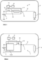
- a vehicle 2 which is only indicated, with an on-board electrical system 4 according to a first embodiment variant is shown.
- the vehicle 2 is in particular a motor vehicle.
- the vehicle electrical system 4 has a voltage source 6 and an electrical load 8.
- the electrical load 8 is an electrical heating element which is, in particular, a heating element for heating a passenger cell or a heating element for heating an operating material of the vehicle 2.
- a demand for the electric load 8 depends on an external condition.
- the external condition is understood here to be a condition for the demand of the electrical load, which in particular is not a property of the load itself.
- the vehicle electrical system 4 also has a load path 10 with an electrical line 12, which connects the voltage source 6 to the electrical load 8.
- the vehicle electrical system 4 has a first switching element 14 which is arranged in the load path 10.
- the first switching element 14 serves to separate the electrical load 8 from the voltage source 6.
- the first switching element 14 is set up in particular for normal connection of the load 8 during operation. That is, it can preferably be operated by a driver of the vehicle 2.
- a work area A B (cf. Fig. 3 ) the external condition, within which a function of the electrical load 8 is meaningful.
- the on-board electrical system 4 also has a control unit 16 which is designed in such a way that the electrical load 8 is prevented from being switched on if the external condition is outside the working range and thus a function and, in particular, an operation of the function of the electrical load 8 does not make sense .
- the external condition is an external temperature.
- the working range A B is a specified temperature range with an upper temperature limit T o , which is followed by a further working range B w (cf. Fig. 3 ).
- the vehicle electrical system 4 has a measuring device 18 to detect the external condition.
- the measuring device 18 is electrically connected to the control unit 16. This makes it possible for the measuring device 18 to transmit a signal to the control unit 16, for example after detecting the external condition, that is to say the external temperature, which signal contains information about the external temperature detected. On the basis of the received signal with the temperature information, for example, a check then takes place by means of the control unit 16 to determine whether the external condition, that is to say the recorded external temperature, is outside the (specified) working range. If the external condition is outside the working range, the control unit 16 prevents the load 8 from being connected. This is the Control unit 16 is electrically connected to first switching element 14 in such a way that control unit 16 transmits, for example, a switching signal to first switching element 14, on the basis of which switching on electrical load 8 is prevented.
- the advantage is achieved that, particularly when the external temperature is used as external condition, a lower temperature load on the electrical line 12 is reached during operation.
- This makes it possible to design a line cross section of the electrical line 12 for a lower temperature range and thus for a lower maximum temperature that occurs and thus to save material and costs.
- a second switching element 20 is arranged in the vehicle electrical system 4.
- the control unit 16 is also set up to cause the electrical load 8 to be disconnected via the second switching element 20 if the external condition is outside the working range.
- This embodiment is based, in particular, on the idea that not only should the electrical load 8 be prevented from being switched on, but also the electrical load 8 should be switched off if, for example, the external condition is outside the working range during operation.
- the second switching element 20 is arranged in series with the first switching element 14 in the exemplary embodiment.
- the second switching element 20 In normal operation of the vehicle electrical system 4 and in particular of the electrical load 8, the second switching element 20 is in a closed, that is to say conductive, state. Preventing the connection of the electrical load 8 is thus preferably implemented via the first switching element 14. Only when this has been switched on (normally) by a driver of vehicle 2, for example, and the external condition is outside the working range, the second switching element 20 opens and thus disconnects the electrical one Load 8 from the voltage source 6.
- the second switching element 20 is also electrically connected to the control unit 16.
- the first switching element 14 and the second switching element 20 are arranged in a power distributor 22.
- the electrical line 12 is connected to the power distributor 22.
- the arrangement of the first switching element 14 and the second switching element 20 in the power distributor 22 makes it possible to form the largest possible length of the electrical line 12 with the reduced line cross-section.
- the cost and material advantage is influenced in this respect.
- This refinement is based on the idea that such power distributors 22 are usually arranged in the vicinity of the voltage source 6, for example the vehicle battery, and thus a large part of the electrical line 12 is "available" for a smaller cross-sectional design.
- a fuse 24 is also arranged in the power distributor 22.
- the fuse serves to protect the electrical line 12 against an overcurrent.
- the fuse 24 is arranged in series with the second switching element 20.
- the fuse 24 is therefore (viewed locally) arranged between the second switching element 20 and the electrical load 8.
- the fuse 24 is, for example, a conventional fuse.
- the first switching element 14 and the second switching element 20 are therefore arranged in a so-called pre-fuse level.
- Fig. 2 shows an on-board network 4 of a vehicle 2 according to a second embodiment variant.
- the on-board network 4 has essentially the same components as the on-board network 4 according to the first embodiment variant Fig. 1 .
- the on-board electrical system 4 thus has a voltage source 6 and an electrical load 8, the requirement for the electrical load 8 likewise depending on an external condition.
- the vehicle electrical system 4 has a load path 10 with an electrical line 12, which connects the voltage source 6 to the electrical load 8.
- the on-board electrical system 4 according to the second embodiment variant also has a first switching element 14 which is arranged in the load path and is designed to separate the electrical load 8 from the voltage source 6.
- the first switching element 14 has a fuse 24, ie the fuse 24 is integrated in the first switching element 14.
- the fuse 24 is also referred to as an integrated fuse 24.
- the first switching element 14 receives - analogously to the first embodiment according to Fig. 1 Switching signals from a control unit 16, which is also arranged within the on-board network 4 and is electrically connected to the first switching element 14.
- the on-board network 4 according to Fig. 2 a second switching element 20 which is designed to disconnect the electrical load 8 from the voltage source 6 when the external condition is outside the working range A B.
- the acquisition of the external condition, here the external temperature, takes place in accordance with the design variant Fig. 2 by means of a measuring device 18 which is arranged within the vehicle electrical system 4 and is electrically connected to the control unit 16.
- the second switching element 20 and the component formed from the first switching element 14 and the fuse 24 are arranged together in a power distributor 22.
- Fig. 3 a sketched representation of an operating range A max of the on-board network 4 is shown.
- the operating range A max is to be understood as a maximum operating range of the vehicle electrical system 4, in particular a maximum temperature operating range A max of the vehicle electrical system 4.
- the maximum operating range A max according to Fig. 3 specifies from which minimum design temperature T min up to which maximum design temperature T max the load paths 10 and in particular the line cross-sections of the load paths 10 of the on-board electrical system 4 are designed.
- the electrical lines 12 must be designed with regard to their line cross-section in such a way that they are not thermally damaged during operation within the operating range A max .
- the operating range A max of the vehicle electrical system 4 has a working range A B with a lower temperature limit T u and an upper temperature limit T o .
- the lower temperature limit T u can be dispensed with.
- the lower temperature limit T u is the minimum design temperature T min .
- the working area A B describes a usually sensible temperature range for the connection of the electrical load 8 connected to the corresponding load path 10 with the voltage source 6. That is, within the working area A B , a connection and overall operation of the electrical load function appears 8 is useful for a driver of vehicle 2, for example.
- the upper temperature limit T o is followed by a further working range B w , within which, in principle, the electrical load 8 can be operated, but no longer appears sensible from the point of view of the driver of the vehicle 2. For example, switching on or operating the electrical load 8 designed as an electrical heating element for heating an interior of the vehicle 2 above a certain temperature, for example above 40 ° C., appears to be inappropriate or even wanted by the driver of the vehicle 2.
- the 40 ° C. in the example described above correspond to the upper temperature limit T o .
Landscapes
- Engineering & Computer Science (AREA)
- Mechanical Engineering (AREA)
- Power Engineering (AREA)
- Air-Conditioning For Vehicles (AREA)
- Control Of Resistance Heating (AREA)
- Electric Propulsion And Braking For Vehicles (AREA)
Applications Claiming Priority (1)
| Application Number | Priority Date | Filing Date | Title |
|---|---|---|---|
| DE102019203918.9A DE102019203918A1 (de) | 2019-03-21 | 2019-03-21 | Bordnetz für ein Fahrzeug sowie Verfahren zur Auslegung einer elektrischen Leitung eines Bordnetzes |
Publications (1)
| Publication Number | Publication Date |
|---|---|
| EP3713031A1 true EP3713031A1 (fr) | 2020-09-23 |
Family
ID=69374134
Family Applications (1)
| Application Number | Title | Priority Date | Filing Date |
|---|---|---|---|
| EP20020036.8A Pending EP3713031A1 (fr) | 2019-03-21 | 2020-01-22 | Réseau de bord d'un véhicule et méthode pour concevoir une ligne électrique d'un réseau de bord |
Country Status (4)
| Country | Link |
|---|---|
| US (1) | US11472357B2 (fr) |
| EP (1) | EP3713031A1 (fr) |
| CN (1) | CN111717137A (fr) |
| DE (1) | DE102019203918A1 (fr) |
Citations (5)
| Publication number | Priority date | Publication date | Assignee | Title |
|---|---|---|---|---|
| DE202005011235U1 (de) * | 2005-07-16 | 2006-12-07 | Brose Fahrzeugteile Gmbh & Co. Kommanditgesellschaft, Coburg | Vorrichtung zum Überlastschutz einer Versorgungsleitung für eine elektrische Last in einem Kraftfahrzeug |
| DE102011122022A1 (de) * | 2011-12-23 | 2013-06-27 | Brose Fahrzeugteile Gmbh & Co. Kg, Hallstadt | Verfahren zum Betrieb eines elektromotorischen Stellantriebs und Stellantrieb |
| DE102013214726A1 (de) * | 2013-07-29 | 2015-01-29 | Bayerische Motoren Werke Aktiengesellschaft | Anordnung zur elektrischen Absicherung eines potentiellen Kurzschlusses bzw. einer Überlast in einem Gleichstromnetz mit systembedingten, variablem Quellinnenwiderstand |
| DE102013225732A1 (de) * | 2013-12-12 | 2015-06-18 | Bayerische Motoren Werke Aktiengesellschaft | Hochvolt-Sicherung für Fahrzeuge |
| DE102017131359A1 (de) * | 2016-12-30 | 2018-07-05 | Infineon Technologies Ag | Elektronische schalt- und schutzschaltung |
Family Cites Families (11)
| Publication number | Priority date | Publication date | Assignee | Title |
|---|---|---|---|---|
| DE19832558B4 (de) * | 1998-07-20 | 2005-10-06 | Infineon Technologies Ag | Halbleiteranordnung mit mindestens einem Halbleiterchip |
| US20030065840A1 (en) * | 2000-03-20 | 2003-04-03 | Toni Kress | Computer-assisted testing method for a wiring system |
| US8605402B2 (en) * | 2009-12-07 | 2013-12-10 | Michael J. Ward | Heat sensor responsive to electrical overloads |
| DE202014003691U1 (de) * | 2013-07-26 | 2014-07-01 | Ellenberger & Poensgen Gmbh | Lastüberwachung mittels einer Überstromschutzeinrichtung |
| JP6411847B2 (ja) * | 2014-10-02 | 2018-10-24 | ルネサスエレクトロニクス株式会社 | 半導体装置、それを備えた車載用電子装置及び自動車 |
| DE102016210058A1 (de) * | 2016-06-08 | 2017-12-14 | Robert Bosch Gmbh | Stromverteiler und Sicherungssystem für ein Fahrzeug |
| US20180292443A1 (en) * | 2017-04-06 | 2018-10-11 | Chengli Li | Leakage current protection device |
| JP6596743B2 (ja) * | 2017-12-28 | 2019-10-30 | 本田技研工業株式会社 | 車両用ステアリング装置 |
| JP6973235B2 (ja) * | 2018-03-28 | 2021-11-24 | 株式会社オートネットワーク技術研究所 | 車載用の電力制御装置及び車載用の電力制御システム |
| US10807628B2 (en) * | 2018-11-16 | 2020-10-20 | Aisin Seiki Kabushiki Kaisha | Steering apparatus |
| US11272790B2 (en) * | 2019-12-19 | 2022-03-15 | Ford Global Technologies, Llc | Vehicle seating assembly |
-
2019
- 2019-03-21 DE DE102019203918.9A patent/DE102019203918A1/de active Pending
-
2020
- 2020-01-22 EP EP20020036.8A patent/EP3713031A1/fr active Pending
- 2020-03-18 CN CN202010189833.2A patent/CN111717137A/zh active Pending
- 2020-03-19 US US16/824,539 patent/US11472357B2/en active Active
Patent Citations (5)
| Publication number | Priority date | Publication date | Assignee | Title |
|---|---|---|---|---|
| DE202005011235U1 (de) * | 2005-07-16 | 2006-12-07 | Brose Fahrzeugteile Gmbh & Co. Kommanditgesellschaft, Coburg | Vorrichtung zum Überlastschutz einer Versorgungsleitung für eine elektrische Last in einem Kraftfahrzeug |
| DE102011122022A1 (de) * | 2011-12-23 | 2013-06-27 | Brose Fahrzeugteile Gmbh & Co. Kg, Hallstadt | Verfahren zum Betrieb eines elektromotorischen Stellantriebs und Stellantrieb |
| DE102013214726A1 (de) * | 2013-07-29 | 2015-01-29 | Bayerische Motoren Werke Aktiengesellschaft | Anordnung zur elektrischen Absicherung eines potentiellen Kurzschlusses bzw. einer Überlast in einem Gleichstromnetz mit systembedingten, variablem Quellinnenwiderstand |
| DE102013225732A1 (de) * | 2013-12-12 | 2015-06-18 | Bayerische Motoren Werke Aktiengesellschaft | Hochvolt-Sicherung für Fahrzeuge |
| DE102017131359A1 (de) * | 2016-12-30 | 2018-07-05 | Infineon Technologies Ag | Elektronische schalt- und schutzschaltung |
Also Published As
| Publication number | Publication date |
|---|---|
| US20200298775A1 (en) | 2020-09-24 |
| DE102019203918A1 (de) | 2020-09-24 |
| CN111717137A (zh) | 2020-09-29 |
| US11472357B2 (en) | 2022-10-18 |
Similar Documents
| Publication | Publication Date | Title |
|---|---|---|
| EP3027472B1 (fr) | Protection contre les surtensions pour un réseau de bord à multiples tensions | |
| EP1411364A1 (fr) | Tableau de bord d'un véhicule pour identifier l'état de batterie connectée au pôle positif de la batterie | |
| EP1564862B2 (fr) | Réseau de bord d'un véhicule avec un transformateur de tension | |
| DE112008003096T5 (de) | Kabelschutzverfahren und Kabelschutzvorrichtung | |
| DE19811626A1 (de) | Stromversorgungsanlage für Fahrzeug | |
| DE102008026737A1 (de) | Kraftfahrzeug-Überstromschutz | |
| EP2985189B1 (fr) | Réseau de bord pour un véhicule, en particulier véhicule industriel | |
| WO2013050207A1 (fr) | Dispositif de diagnostic pour un réseau de bord à plusieurs tensions, réseau de bord à plusieurs tensions et procédé de fonctionnement d'un réseau de bord à plusieurs tensions | |
| DE102009023801A1 (de) | Sicherungsvorrichtung mit pyrotechnischer Sicherung | |
| DE102014222878A1 (de) | Kraftfahrzeug-Versorgungsnetz | |
| DE202005011235U1 (de) | Vorrichtung zum Überlastschutz einer Versorgungsleitung für eine elektrische Last in einem Kraftfahrzeug | |
| DE102011083582A1 (de) | Stromverteiler für Kraftfahrzeug-Bordnetze | |
| WO2005078891A1 (fr) | Reseau de bord de vehicule automobile a conservation du courant d'alternateur separee de la batterie | |
| DE202014003691U1 (de) | Lastüberwachung mittels einer Überstromschutzeinrichtung | |
| DE102009019825B4 (de) | Schaltungsanordnung zur Stromversorgung von Verbrauchern eines Kraftfahrzeugs | |
| DE102011105971A1 (de) | Bordnetzanordnung für ein Kraftfahrzeug | |
| EP3713031A1 (fr) | Réseau de bord d'un véhicule et méthode pour concevoir une ligne électrique d'un réseau de bord | |
| DE10248415B4 (de) | Stromversorgungsschaltung für ein Kraftfahrzeug mit zwei unterschiedlichen Verbraucherspannungen | |
| DE102012023460A1 (de) | Kraftfahrzeug-Bordnetz und Verfahren zum Erkennen eines Lichtbogens in einem Kraftfahrzeug-Bordnetz | |
| DE102016121447B4 (de) | Vorrichtung und Verfahren zum Absichern einer Bordnetzkomponente eines Fahrzeug-Bordnetzes | |
| DE102010043902B4 (de) | Einrichtung und Verfahren zum Schutz eines zum Laden von Elektrofahrzeugen dienenden Ladekabels | |
| DE102018210979B4 (de) | Mehrspannungsbatterievorrichtung und Mehrspannungsbordnetz für ein Kraftfahrzeug | |
| EP3820733B1 (fr) | Dispositif de batterie multi-tension et réseau de bord pour un véhicule automobile | |
| DE102018206648B4 (de) | Leitungsnetz sowie Versorgungsleitung für ein solches Leitungsnetz | |
| EP1564077A1 (fr) | Distributeur de courant éléctronique pour un réseau de bord d'un véhicule automobile |
Legal Events
| Date | Code | Title | Description |
|---|---|---|---|
| PUAI | Public reference made under article 153(3) epc to a published international application that has entered the european phase |
Free format text: ORIGINAL CODE: 0009012 |
|
| STAA | Information on the status of an ep patent application or granted ep patent |
Free format text: STATUS: REQUEST FOR EXAMINATION WAS MADE |
|
| STAA | Information on the status of an ep patent application or granted ep patent |
Free format text: STATUS: EXAMINATION IS IN PROGRESS |
|
| 17P | Request for examination filed |
Effective date: 20200217 |
|
| AK | Designated contracting states |
Kind code of ref document: A1 Designated state(s): AL AT BE BG CH CY CZ DE DK EE ES FI FR GB GR HR HU IE IS IT LI LT LU LV MC MK MT NL NO PL PT RO RS SE SI SK SM TR |
|
| AX | Request for extension of the european patent |
Extension state: BA ME |
|
| 17Q | First examination report despatched |
Effective date: 20200904 |
|
| STAA | Information on the status of an ep patent application or granted ep patent |
Free format text: STATUS: EXAMINATION IS IN PROGRESS |
|
| RBV | Designated contracting states (corrected) |
Designated state(s): AL AT BE BG CH CY CZ DE DK EE ES FI FR GB GR HR HU IE IS IT LI LT LU LV MC MK MT NL NO PL PT RO RS SE SI SK SM TR |