EP3712608A1 - Inspection system, control method, and storage medium - Google Patents
Inspection system, control method, and storage medium Download PDFInfo
- Publication number
- EP3712608A1 EP3712608A1 EP18878645.3A EP18878645A EP3712608A1 EP 3712608 A1 EP3712608 A1 EP 3712608A1 EP 18878645 A EP18878645 A EP 18878645A EP 3712608 A1 EP3712608 A1 EP 3712608A1
- Authority
- EP
- European Patent Office
- Prior art keywords
- probe
- angle
- controller
- weld portion
- around
- Prior art date
- Legal status (The legal status is an assumption and is not a legal conclusion. Google has not performed a legal analysis and makes no representation as to the accuracy of the status listed.)
- Granted
Links
Images




Classifications
-
- G—PHYSICS
- G01—MEASURING; TESTING
- G01N—INVESTIGATING OR ANALYSING MATERIALS BY DETERMINING THEIR CHEMICAL OR PHYSICAL PROPERTIES
- G01N29/00—Investigating or analysing materials by the use of ultrasonic, sonic or infrasonic waves; Visualisation of the interior of objects by transmitting ultrasonic or sonic waves through the object
- G01N29/22—Details, e.g. general constructional or apparatus details
- G01N29/26—Arrangements for orientation or scanning by relative movement of the head and the sensor
- G01N29/265—Arrangements for orientation or scanning by relative movement of the head and the sensor by moving the sensor relative to a stationary material
-
- G—PHYSICS
- G01—MEASURING; TESTING
- G01B—MEASURING LENGTH, THICKNESS OR SIMILAR LINEAR DIMENSIONS; MEASURING ANGLES; MEASURING AREAS; MEASURING IRREGULARITIES OF SURFACES OR CONTOURS
- G01B17/00—Measuring arrangements characterised by the use of infrasonic, sonic or ultrasonic vibrations
-
- G—PHYSICS
- G01—MEASURING; TESTING
- G01N—INVESTIGATING OR ANALYSING MATERIALS BY DETERMINING THEIR CHEMICAL OR PHYSICAL PROPERTIES
- G01N29/00—Investigating or analysing materials by the use of ultrasonic, sonic or infrasonic waves; Visualisation of the interior of objects by transmitting ultrasonic or sonic waves through the object
- G01N29/04—Analysing solids
- G01N29/043—Analysing solids in the interior, e.g. by shear waves
-
- G—PHYSICS
- G01—MEASURING; TESTING
- G01N—INVESTIGATING OR ANALYSING MATERIALS BY DETERMINING THEIR CHEMICAL OR PHYSICAL PROPERTIES
- G01N29/00—Investigating or analysing materials by the use of ultrasonic, sonic or infrasonic waves; Visualisation of the interior of objects by transmitting ultrasonic or sonic waves through the object
- G01N29/04—Analysing solids
- G01N29/07—Analysing solids by measuring propagation velocity or propagation time of acoustic waves
-
- G—PHYSICS
- G01—MEASURING; TESTING
- G01N—INVESTIGATING OR ANALYSING MATERIALS BY DETERMINING THEIR CHEMICAL OR PHYSICAL PROPERTIES
- G01N29/00—Investigating or analysing materials by the use of ultrasonic, sonic or infrasonic waves; Visualisation of the interior of objects by transmitting ultrasonic or sonic waves through the object
- G01N29/22—Details, e.g. general constructional or apparatus details
- G01N29/225—Supports, positioning or alignment in moving situation
-
- G—PHYSICS
- G01—MEASURING; TESTING
- G01N—INVESTIGATING OR ANALYSING MATERIALS BY DETERMINING THEIR CHEMICAL OR PHYSICAL PROPERTIES
- G01N29/00—Investigating or analysing materials by the use of ultrasonic, sonic or infrasonic waves; Visualisation of the interior of objects by transmitting ultrasonic or sonic waves through the object
- G01N29/22—Details, e.g. general constructional or apparatus details
- G01N29/32—Arrangements for suppressing undesired influences, e.g. temperature or pressure variations, compensating for signal noise
-
- G—PHYSICS
- G01—MEASURING; TESTING
- G01N—INVESTIGATING OR ANALYSING MATERIALS BY DETERMINING THEIR CHEMICAL OR PHYSICAL PROPERTIES
- G01N2291/00—Indexing codes associated with group G01N29/00
- G01N2291/01—Indexing codes associated with the measuring variable
- G01N2291/011—Velocity or travel time
-
- G—PHYSICS
- G01—MEASURING; TESTING
- G01N—INVESTIGATING OR ANALYSING MATERIALS BY DETERMINING THEIR CHEMICAL OR PHYSICAL PROPERTIES
- G01N2291/00—Indexing codes associated with group G01N29/00
- G01N2291/02—Indexing codes associated with the analysed material
- G01N2291/023—Solids
- G01N2291/0234—Metals, e.g. steel
-
- G—PHYSICS
- G01—MEASURING; TESTING
- G01N—INVESTIGATING OR ANALYSING MATERIALS BY DETERMINING THEIR CHEMICAL OR PHYSICAL PROPERTIES
- G01N2291/00—Indexing codes associated with group G01N29/00
- G01N2291/02—Indexing codes associated with the analysed material
- G01N2291/028—Material parameters
- G01N2291/0289—Internal structure, e.g. defects, grain size, texture
-
- G—PHYSICS
- G01—MEASURING; TESTING
- G01N—INVESTIGATING OR ANALYSING MATERIALS BY DETERMINING THEIR CHEMICAL OR PHYSICAL PROPERTIES
- G01N2291/00—Indexing codes associated with group G01N29/00
- G01N2291/04—Wave modes and trajectories
- G01N2291/044—Internal reflections (echoes), e.g. on walls or defects
-
- G—PHYSICS
- G01—MEASURING; TESTING
- G01N—INVESTIGATING OR ANALYSING MATERIALS BY DETERMINING THEIR CHEMICAL OR PHYSICAL PROPERTIES
- G01N2291/00—Indexing codes associated with group G01N29/00
- G01N2291/10—Number of transducers
- G01N2291/105—Number of transducers two or more emitters, two or more receivers
-
- G—PHYSICS
- G01—MEASURING; TESTING
- G01N—INVESTIGATING OR ANALYSING MATERIALS BY DETERMINING THEIR CHEMICAL OR PHYSICAL PROPERTIES
- G01N2291/00—Indexing codes associated with group G01N29/00
- G01N2291/10—Number of transducers
- G01N2291/106—Number of transducers one or more transducer arrays
-
- G—PHYSICS
- G01—MEASURING; TESTING
- G01N—INVESTIGATING OR ANALYSING MATERIALS BY DETERMINING THEIR CHEMICAL OR PHYSICAL PROPERTIES
- G01N2291/00—Indexing codes associated with group G01N29/00
- G01N2291/26—Scanned objects
- G01N2291/267—Welds
- G01N2291/2672—Spot welding
Definitions
- Embodiments of the invention relate to an inspection system, a control method, and a storage medium.
- one member is made by joining portions of two or more components to each other by melting.
- the member that is made by welding is inspected for whether or not the welded portion (hereinbelow, called the weld portion) is joined appropriately.
- a probe that includes ultrasonic sensors is caused to contact the weld portion.
- an ultrasonic wave is transmitted toward the weld portion; and the existence or absence of the joint is verified based on the reflected wave.
- the angle of the probe with respect to the member affects the inspection result. For example, when the inspection is performed at an inappropriate angle, there is a possibility that an incomplete weld may be determined despite actually being joined appropriately. Therefore, it is desirable for the angle of the probe to be set to an appropriate value. In particular, it is desirable to develop technology so that the angle of the probe can be adjusted to a more appropriate value for an inspection apparatus in which multiple ultrasonic sensors are arranged.
- Patent Document 1 Japanese Patent No. 5618529
- a problem to be solved by the invention is to provide an inspection system, a control method, and a storage medium in which the angle of the probe can be adjusted to a more appropriate value.
- an inspection system includes a probe and a controller.
- the probe includes a plurality of ultrasonic sensors arranged in a first direction.
- the probe contacts a weld portion by moving in a second direction crossing the first direction.
- Each of the plurality of ultrasonic sensors transmits an ultrasonic wave toward the weld portion and receives a reflected wave.
- the controller detects a joint and a non-joint at a plurality of points along the first direction of the weld portion based on the plurality of reflected waves.
- the controller adjusts an angle of the probe around a third direction based on a number of the joints or the non-joints detected for the plurality of points.
- the third direction is perpendicular to the first direction and crossing the second direction.
- FIG. 1 is a schematic view illustrating an inspection system according to an embodiment.
- FIG. 2 is a perspective view illustrating a portion of the inspection system according to the embodiment.
- the inspection system 100 is for a non-destructive inspection of a weld portion in which two or more components are formed as one body.
- the inspection system 100 includes an inspection apparatus 1 and a controller 2.
- the inspection apparatus 1 includes a probe 10, an imager 20, a coater 30, and a robot arm (hereinbelow, called the arm) 40.
- the probe 10 includes multiple ultrasonic sensors used in the inspection of the weld portion.
- the imager 20 images the welded member and acquires an image.
- the imager 20 extracts the weld mark from the image and detects the position of the weld portion.
- the coater 30 coats a couplant onto the upper surface of the weld portion.
- the couplant is used to provide acoustic matching of the ultrasonic wave between the probe 10 and the inspection object.
- the couplant may be a liquid or a gel.
- the probe 10, the imager 20, and the coater 30 are provided at the tip of the arm 40 as illustrated in FIG. 2 .
- the arm 40 is, for example, an articulated robot.
- the positions of the probe 10, the imager 20, and the coater 30 can be changed by driving the arm 40.
- the controller 2 controls the operations of these components included in the inspection apparatus 1.
- the inspection apparatus 1 is connected to a device including the controller 2 by wired communication or wireless communication.
- the inspection system 100 according to the embodiment may be realized by providing the controller 2 in the inspection apparatus 1.
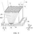
- FIG. 3 is a schematic view illustrating the internal structure of the probe tip of the inspection system according to the embodiment.
- a matrix sensor 11 illustrated in FIG. 3 is provided in the interior of the probe 10 tip.
- the matrix sensor 11 includes multiple ultrasonic sensors 12.
- the ultrasonic sensors 12 are, for example, transducers.
- the multiple ultrasonic sensors 12 are arranged in a first direction D1 and a third direction D3 which are orthogonal to each other.
- the probe 10 contacts the inspection object by moving in a second direction D2 crossing a plane including the first direction D1 and the third direction D3.
- the second direction D2 is perpendicular to the plane including the first direction D1 and the third direction D3.
- FIG. 3 illustrates the state of inspecting a member 5.
- the member 5 is made by performing spot welding of a metal plate 51 and a metal plate 52 at a weld portion 53.
- a solidified portion 54 is formed at the weld portion 53 by melting, mixing, and solidifying a portion of the metal plate 51 and a portion of the metal plate 52.
- Each of the ultrasonic sensors 12 transmits an ultrasonic wave US toward the member 5 coated with a couplant 55 and receives a reflected wave RW from the member 5.
- one ultrasonic sensor 12 transmits the ultrasonic wave US toward the weld portion 53.
- a portion of the ultrasonic wave US is reflected by the front surface or the bottom surface of the member 5, etc.
- Each of the multiple ultrasonic sensors 12 receives and detects the reflected wave RW.
- the weld portion 53 vicinity of the member 5 is inspected two-dimensionally by the ultrasonic sensors 12 each sequentially transmitting the ultrasonic wave US and by the multiple ultrasonic sensors 12 receiving each of the reflected waves RW.
- FIG. 4 is a flowchart illustrating an overview of the operation of the inspection system according to the embodiment.
- the imager 20 images the member 5 and detects the position of the weld portion 53 from the acquired image (step S1).
- the arm 40 moves the coater 30 to a position opposing the weld portion 53 in the second direction D2.
- the coater 30 coats the couplant onto the weld portion (step S2).
- the arm 40 moves the probe 10 in the second direction D2 and causes the probe 10 to contact the weld portion 53 (step S3).
- the multiple ultrasonic sensors 12 transmit the ultrasonic waves US toward the member 5 including the weld portion 53 and receive the reflected waves RW.
- the controller 2 adjusts the angle of the probe 10 based on the multiple reflected waves RW (step S4).
- the weld portion 53 is inspected by the multiple ultrasonic sensors 12 (step S5).
- the controller 2 determines whether or not an uninspected weld portion 53 exists (step S6).
- step S7 the controller 2 drives the arm 40 and moves the probe 10, the imager 20, and the coater 30 toward another weld portion 53. Subsequently, steps S1 to S6 are performed again.
- FIGS. 5A to 5C are schematic views for describing the inspection method using the inspection system according to the embodiment.
- a portion of the ultrasonic wave US is reflected by an upper surface 5a of the metal plate 51 or an upper surface 5b of the weld portion 53.
- the other portion of the ultrasonic wave US enters the member 5 and is reflected by a bottom surface 5c of the metal plate 51 or a bottom surface 5d of the weld portion 53.
- the positions in the second direction D2 of the upper surface 5a, the upper surface 5b, the bottom surface 5c, and the bottom surface 5d are different from each other.
- the distances in the second direction D2 between the ultrasonic sensor 12 and these surfaces are different from each other.
- the peak of the intensity of the reflected wave is detected when the ultrasonic sensor 12 receives the reflected waves from these surfaces. Which surface reflected the ultrasonic wave US can be verified by calculating the time until each peak is detected after transmitting the ultrasonic wave US.
- FIG. 5B and FIG. 5C are graphs illustrating the relationship between the time after transmitting the ultrasonic wave US and the intensity of the reflected wave RW.
- the graph of FIG. 5B illustrates the reception result of the reflected waves RW from the upper surface 5a and the bottom surface 5c of the metal plate 51.
- the graph of FIG. 5C illustrates the reception result of the reflected waves RW from the upper surface 5b and the bottom surface 5d of the weld portion 53.
- a peak Pe1 occurring first is based on the reflected wave RW from the upper surface 5a.
- a peak Pe2 occurring second is based on the reflected wave RW from the bottom surface 5c.
- the times when the peak Pe1 and the peak Pe2 are detected correspond respectively to the positions in the second direction D2 of the upper surface 5a and the bottom surface 5c of the metal plate 51.
- a time difference TD1 between the time when the peak Pe1 is detected and the time when the peak Pe2 is detected corresponds to a distance Di1 in the second direction D2 between the upper surface 5a and the bottom surface 5c.
- a peak Pe3 occurring first is based on the reflected wave RW from the upper surface 5b.
- a peak Pe4 occurring second is based on the reflected wave RW from the bottom surface 5d.
- the times when the peak Pe3 and the peak Pe4 are detected correspond respectively to the positions in the second direction D2 of the upper surface 5b and the bottom surface 5d of the weld portion 53.
- a time difference TD2 between the time when the peak Pe3 is detected and the time when the peak Pe4 is detected corresponds to a distance Di2 in the second direction D2 between the upper surface 5b and the bottom surface 5d.
- the positions in the second direction D2 of the surfaces reflecting the ultrasonic wave US can be detected by detecting the time until detecting the peak occurring first (a first peak) and the peak occurring second (a second peak) of the reflected wave RW after transmitting the ultrasonic wave US.
- the distance in the second direction D2 between the surfaces reflecting the ultrasonic wave US can be detected from the difference between the time when the peak occurring first is detected and the time when the peak occurring second is detected.
- step S4 The method for adjusting the angle performed in step S4 will now be described in detail.
- FIG. 6 is a flowchart illustrating the method for adjusting the probe angle using the inspection system according to the embodiment.
- FIGS. 7A to 7D are figures for describing the inspection system according to the embodiment.
- the ultrasonic waves US are transmitted from the multiple ultrasonic sensors 12; and the reflected waves RW are received (step S401).
- the ultrasonic sensors 12 each sequentially transmit the ultrasonic wave US; and the multiple ultrasonic sensors 12 receive each of the reflected waves RW.
- FIG. 7A and FIG. 7D are plan views illustrating the weld portion 53 vicinity of the member 5.
- the structure of a detection area DA illustrated in FIG. 7A is detected by step S401.
- a joint or a non-joint is detected for each point of the detection area DA.
- the controller 2 adjusts the angle around the third direction D3 of the probe 10 based on the detection result along a line segment L1 along the first direction D1.
- the line segment L1 is positioned at the center vicinity in the third direction D3 of the detection area DA.
- FIG. 7B is an example of the detection result at each point along the line segment L1.
- the vertical axis is the position in the second direction D2.
- the horizontal axis is the position in the first direction D1.
- ⁇ (the white circles) illustrate the position in the second direction D2 of the first reflective surface (the first reflective surface) of the member 5.
- ⁇ illustrate the position of the upper surface 5a or the position of the upper surface 5b.
- ⁇ illustrate the position in the second direction D2 of the second reflective surface (the second reflective surface) of the member 5.
- ⁇ illustrate the position of the bottom surface 5c or the position of the bottom surface 5d.
- these positions are calculated based on the time until the peak of the reflected wave RW is detected after transmitting the ultrasonic wave US.
- ⁇ illustrate the detection result of the joint and the non-joint described below.
- the distance between the first reflective surface and the second reflective surface is short in the detection result at the end vicinities in the first direction D1 of the line segment L1.
- the distance between the first reflective surface and the second reflective surface is long in the detection result at the center in the first direction D1. This shows that the ultrasonic wave US is reflected by the upper surface 5b and the bottom surface 5d.
- the controller 2 calculates the distance between the first reflective surface and the second reflective surface. For example, in the case where the distance is not less than a preset threshold, the controller 2 determines that the point is joined. In the case where the distance is less than the threshold, the controller 2 determines that the point is not joined. In the graph illustrated in FIG. 7B , the points that are determined to be joined are illustrated by the value of 1; and the points determined not to be joined are illustrated by the value of 0.
- the controller 2 detects the joint and the non-joint at the multiple points along the first direction D1 of the member 5.
- the controller 2 extracts the number of times the joint is detected (hereinbelow, called the detection number) (step S402).
- the controller 2 determines whether or not the detection number is not less than a preset threshold (step S403).
- the threshold is set based on the dimension in the first direction D1 of the weld portion 53, the density of the ultrasonic sensors 12 in the first direction D1, etc.
- step S5 illustrated in FIG. 4 may be omitted. This is because a sufficient detection number already has been detected; and the weld portion 53 can be considered to be joined appropriately.
- the controller 2 compares a number of times m1 that steps S401 and S402 have been performed to a preset value n1 (step S404).
- step S405 the controller 2 changes the angle around the third direction D3 of the probe 10 (step S405).
- step S401 is re-performed.
- step S401 and step S402 are performed repeatedly while changing the angle around the third direction D3.
- the controller 2 derives the appropriate first angle around the third direction D3 of the probe 10 from the detection result up to that time (step S406).
- FIG. 7C illustrates an example of the detection result obtained by repeating steps S401 to S405.
- the horizontal axis is the angle around the third direction D3; and the vertical axis is the detection number at each angle.
- the controller 2 sets an angle ⁇ 1 having the highest detection number as the first angle.
- the controller 2 may generate a quadratic function QF of the relationship between the angle and the detection number and set an angle ⁇ 2 where the quadratic function QF has a flexion point as the first angle.
- the controller 2 sets the angle around the third direction D3 of the probe 10 as the first angle (step S407).
- the ultrasonic waves US are transmitted from the multiple ultrasonic sensors 12; and the reflected waves RW are received (step S408).
- the ultrasonic sensors 12 each sequentially transmit the ultrasonic wave US; and the multiple ultrasonic sensors 12 receive each of the reflected waves RW.
- the structure of the detection area DA is detected by step S408.
- the controller 2 adjusts the angle around the third direction D3 of the probe 10 based on the detection result along a line segment L2 along the third direction D3 illustrated in FIG. 7D .
- the line segment L2 is positioned at the center vicinity in the first direction D1 of the detection area DA.
- step S402 the controller 2 extracts the detection number for the multiple points along the third direction D3 of the member 5 (step S409).
- the controller 2 determines whether or not the detection number is not less than the preset threshold (step S410).
- the threshold is set based on the dimension in the third direction D3 of the weld portion 53, the density of the ultrasonic sensors 12 in the third direction D3, etc.
- the controller 2 maintains the angle around the first direction D1 of the probe 10 and ends the angle adjustment. In the case where the detection number is less than the threshold, the controller 2 compares a number of times m2 that steps S408 and S409 have been performed to a preset value n2 (step S411).
- the controller 2 changes the angle around the first direction D1 of the probe 10 (step S412). Then, steps S408 to S410 are re-performed.
- the controller 2 derives the appropriate second angle around the first direction D1 of the probe 10 from the detection result up to that time (step S413).
- the derivation of the second angle is performed similarly to the method of step S406.
- the controller 2 sets the angle around the first direction D1 of the probe 10 as the second angle (step S414).
- the angle of the probe 10 is adjusted appropriately; subsequently, the inspection of the weld portion 53 is performed by the probe 10.
- step S411 shows that many points of the non-joint exist in the weld portion 53. This is because a sufficient detection number is not obtained in the previous steps even though the detection was performed while changing the angle of the probe 10. Accordingly, in the case where the number of times m2 is not less than the value n2 in step S411, the weld portion 53 may be determined to be a non-joint. In such a case, the angle adjustment ends; and step S5 illustrated in FIG. 4 is omitted.
- the angle of the probe 10 is adjusted using, from the detection results of all of the ultrasonic sensors 12 included in the matrix sensor 11, the detection result along the line segment L1 along the first direction D1 and the detection result along a line segment L3 along the third direction D3.
- the control method of the angle adjustment of the inspection system 100 according to the embodiment is not limited thereto.
- the detection of the joint and the non-joint at the multiple points along the first direction D1 of the member 5 may be performed using only a portion of the multiple ultrasonic sensors 12 along the first direction D1.
- the detection of the joint and the non-joint at the multiple points along the third direction D3 of the member 5 may be performed using only a portion of the multiple ultrasonic sensors 12 along the third direction D3.
- the specific detection method of the inspection system 100 according to the embodiment is modifiable as appropriate as long as the detection result of the joint and the non-joint at multiple points along a designated direction is obtained. This is similar for the control method of the angle adjustment described below as well.
- FIG. 8 is a figure for describing effects of the inspection system according to the embodiment.
- the two horizontal axes are respectively an angle ⁇ D1 around the first direction D1 and an angle ⁇ D3 around the third direction D3.
- the vertical axis is the detection number.
- Points P1 to P5 of FIG. 8 illustrate the path of the changes of the detection number when the angle ⁇ D1 and the angle ⁇ D3 are changed.
- the method for adjusting the angle described above realizes an increase of the detection number while changing the angle ⁇ D1 around the first direction D1 and the angle ⁇ D3 around the third direction D3. As illustrated by the points P1 to P5 of FIG. 8 , this method corresponds to climbing the hill of the detection number toward a higher position. A larger detection number shows that the member 5 can be inspected using a more appropriate angle.
- the angle around the first direction D1 or around the third direction D3 is adjusted based on the number of times the joint is detected for the multiple points along the first direction D1 or the third direction D3 of the member 5.
- the inspection system 100 and the control method according to the embodiment are not limited to the example.
- the angle around the first direction D1 or around the third direction D3 may be adjusted based on the number of times the non-joint is detected for the multiple points along the first direction D1 or the third direction D3 of the member 5. In such a case, the angle around the first direction D1 or around the third direction D3 is adjusted to reduce the number of times the non-joint is detected.
- the angle of the probe 10 may be adjusted using the number of times the non-joint is detected instead of the number of times the joint is detected.
- the joint and the non-joint are detected at the multiple points along the first direction D1 of the weld portion 53. Then, the angle of the probe 10 around the third direction D3 is adjusted based on the number of the joints or the non-joints detected for these multiple points. The inventors discovered that the angle around the third direction D3 of the probe 10 can be adjusted to a more appropriate value by using this method. In other words, according to the embodiment, for a probe in which multiple ultrasonic sensors are arranged, the angle of the probe can be adjusted to a more appropriate value.
- the controller 2 extracts the detection number at each angle while changing the angle around the third direction D3 of the probe 10. Then, the controller 2 sets the first angle at which the detection number exceeds the preset threshold as the angle around the third direction D3 of the probe 10. According to this method, the range of angles for which the detection number is verified can be narrow; and a more appropriate angle around the third direction D3 can be detected in a shorter period of time.
- the controller 2 may set the first angle having the highest detection number as the angle around the third direction D3 of the probe 10. Or, the controller 2 may generate a quadratic function of the relationship between the angle and the detection number while changing the angle around the third direction D3 of the probe 10 within the first range. The controller 2 sets the first angle where the quadratic function has a flexion point as the angle around the third direction D3 of the probe 10.
- the first range is set according to the precision necessary for the inspection of the weld portion 53. Typically, it is easier to set a more appropriate angle as the first range increases. According to these methods, a more appropriate angle around the third direction D3 can be detected.
- the first angle for which the value of the detection number is estimated to be large can be determined efficiently based on the quadratic function.
- the controller 2 extracts the detection number at each angle while changing the angle around the first direction D1 of the probe 10.
- the controller 2 sets the angle where the detection number exceeds the preset threshold as the angle around the third direction D3 of the probe 10.
- the controller 2 may set the angle having the highest detection number as the angle around the third direction D3 of the probe 10. Or, the controller 2 may generate a quadratic function of the relationship between the angle and the detection number and set the angle where the quadratic function has a flexion point as the angle around the third direction D3 of the probe 10.
- the angle around the first direction D1 of the probe 10 and the angle around the third direction D3 are adjusted to more appropriate values.
- the angle adjustment may be performed by the following methods.
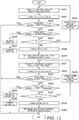
- FIGS. 9A and 9B are flowcharts illustrating another method for adjusting the probe angle using the inspection system according to the embodiment.
- FIG. 10 is a graph illustrating data detected by the inspection system according to the embodiment.
- the ultrasonic sensors 12 each sequentially transmit the ultrasonic wave US; and the multiple ultrasonic sensors 12 receive each of the reflected waves RW (step S421).
- FIG. 10 illustrates the data detected by the multiple ultrasonic sensors 12 arranged in the first direction D1 in step S421.
- the vertical axis is the position in the second direction D2.
- the horizontal axis is the position in the first direction D1 of each of the ultrasonic sensors 12.
- the controller 2 calculates a first tilt around the third direction D3 of the upper surface 5b or the bottom surface 5d from the detection result (step S422). For example, the controller 2 generates a linear function LF as illustrated in FIG. 10 using only the results determined to be the joint.
- the linear function LF is of the relationship between the position in the first direction D1 and the position in the second direction D2.
- the linear function LF is generated based on the reflected waves RW of the upper surface 5b or the bottom surface 5d. More favorably, the linear function LF is generated based on the reflected wave RW of the bottom surface 5d as illustrated in FIG. 10 .
- the slope of the linear function LF is taken as the first tilt.
- a large first tilt indicates that the tilt around the third direction D3 of the matrix sensor 11 with respect to the upper surface 5b or the bottom surface 5d is large.
- the controller 2 detects the direction of the first tilt and the magnitude of the first tilt and changes the angle around the third direction D3 of the probe 10 to correct the first tilt (step S423). For example, the controller 2 increases the angle to be changed as the first tilt increases.
- the correction of the tilt means to set the tilt to be 0 and to set the linear function LF to be substantially parallel to the horizontal axis.
- the tilt of the matrix sensor 11 with respect to the upper surface 5b and the bottom surface 5d can be reduced thereby.
- step S424 the multiple ultrasonic sensors 12 that are arranged in the third direction D3 each sequentially transmit the ultrasonic wave US; and the multiple ultrasonic sensors 12 receive each of the reflected waves RW (step S424).
- the controller 2 calculates a second tilt around the first direction D1 of the upper surface 5b or the bottom surface 5d (step S425).
- a large second tilt indicates that the tilt around the first direction D1 of the matrix sensor 11 with respect to the upper surface 5b or the bottom surface 5d is large.
- step S423 the controller 2 changes the second angle around the first direction D1 of the probe 10 to correct the second tilt (step S426).
- steps S425 and S426 may be performed in parallel with steps S422 and S423 based on the detection result obtained in step S421. According to this method, the time necessary for the angle adjustment of the probe 10 can be shortened because step S424 described above can be omitted.
- At least one of the angle around the first direction D1 or the angle around the third direction D3 of the probe 10 can be adjusted to a more appropriate value based on the detection result of performing the detection once. Therefore, the number of times the detection is performed for the angle adjustment of the probe 10 can be reduced; and the time necessary for the angle adjustment can be shortened.
- the method illustrated in the flowchart of FIG. 6 and the method illustrated in the flowchart of FIG. 9 may be performed in combination.
- FIG. 11 is a flowchart illustrating another method for adjusting the probe angle using the inspection system according to the embodiment.
- the multiple ultrasonic sensors 12 each sequentially transmit the ultrasonic wave US; and the multiple ultrasonic sensors 12 receive each of the reflected waves RW (step S441).
- the controller 2 extracts the detection number for the multiple points along the first direction D1 of the member 5 (step S442).
- the controller 2 determines whether or not the detection number is not less than a preset first threshold (step S443).
- a value of the detection number sufficient to determine that the entire weld portion 53 is sufficiently joined is set as the first threshold.
- the angle of the probe 10 is determined to be appropriate; and the angle adjustment of the probe 10 ends.
- the controller 2 determines whether or not the detection number is not less than a preset second threshold (step S444).
- the second threshold is less than the first threshold.
- a value of the detection number sufficient to calculate the first tilt is set as the second threshold.
- the first tilt is calculated similarly to the flowchart illustrated in FIG. 9 (step S445); and the angle around the third direction D3 of the probe 10 is adjusted to correct the first tilt (step S446).
- step S447 the number of times m1 that steps S441 to S444 have been performed is compared to the preset value n1 (step S447).
- the controller 2 changes the angle around the third direction D3 of the probe 10 (step S448).
- step S441 is re-performed.
- the controller 2 derives the appropriate first angle around the third direction D3 of the probe 10 from the detection result up to that time (step S449).
- the controller 2 sets the angle around the third direction D3 of the probe 10 as the first angle (step S450).
- the multiple ultrasonic sensors 12 each sequentially transmit the ultrasonic wave US; and the multiple ultrasonic sensors 12 receive each of the reflected waves RW (step S451).
- the controller 2 extracts the detection number for the multiple points along the third direction D3 of the member 5 (step S452).
- the controller 2 determines whether or not the detection number is not less than a preset third threshold (step S453).
- a value of the detection number sufficient to determine that the entire weld portion 53 is sufficiently joined is set as the third threshold.
- the angle of the probe 10 is determined to be appropriate; and the angle adjustment of the probe 10 ends.
- the controller 2 determines whether or not the detection number is not less than a preset fourth threshold (step S454).
- the fourth threshold is less than the third threshold.
- a value of the detection number sufficient to calculate the second tilt is set as the fourth threshold.
- the second tilt is calculated similarly to the flowchart illustrated in FIG. 9 (step S455); and the angle around the first direction D1 of the probe 10 is adjusted to correct the second tilt (step S456).
- step S457 the number of times m2 that steps S451 to S454 have been performed is compared to the preset value n2 (step S457).
- the controller 2 changes the angle around the first direction D1 of the probe 10 (step S458).
- step S451 is re-performed.
- the controller 2 derives the appropriate second angle around the first direction D1 of the probe 10 from the detection result up to that time (step S459).
- the controller 2 sets the angle around the third direction D3 of the probe 10 as the second angle (step S460).
- Step S451 may be omitted from the flowchart illustrated in FIG. 11 .
- step S452 is performed based on the detection result acquired in step S441. According to this method, the time necessary for the angle adjustment of the probe 10 can be shortened.
- the embodiments of the invention include the following programs.
- the angle of the probe 10 can be adjusted to a more appropriate value.
- the angle of the probe 10 can be adjusted to a more appropriate value by using a program or a storage medium in which the program is stored to cause the controller 2 to perform the control method described above.
Landscapes
- Physics & Mathematics (AREA)
- General Physics & Mathematics (AREA)
- General Health & Medical Sciences (AREA)
- Chemical & Material Sciences (AREA)
- Analytical Chemistry (AREA)
- Biochemistry (AREA)
- Life Sciences & Earth Sciences (AREA)
- Health & Medical Sciences (AREA)
- Immunology (AREA)
- Pathology (AREA)
- Acoustics & Sound (AREA)
- Investigating Or Analyzing Materials By The Use Of Ultrasonic Waves (AREA)
- Length Measuring Devices Characterised By Use Of Acoustic Means (AREA)
- Debugging And Monitoring (AREA)
Abstract
Description
- Embodiments of the invention relate to an inspection system, a control method, and a storage medium.
- In welding, one member is made by joining portions of two or more components to each other by melting. The member that is made by welding is inspected for whether or not the welded portion (hereinbelow, called the weld portion) is joined appropriately. For example, in a non-destructive inspection, a probe that includes ultrasonic sensors is caused to contact the weld portion. Then, an ultrasonic wave is transmitted toward the weld portion; and the existence or absence of the joint is verified based on the reflected wave.
- In the inspection, the angle of the probe with respect to the member affects the inspection result. For example, when the inspection is performed at an inappropriate angle, there is a possibility that an incomplete weld may be determined despite actually being joined appropriately. Therefore, it is desirable for the angle of the probe to be set to an appropriate value. In particular, it is desirable to develop technology so that the angle of the probe can be adjusted to a more appropriate value for an inspection apparatus in which multiple ultrasonic sensors are arranged.
- [Patent Document 1] Japanese Patent No.
5618529 - A problem to be solved by the invention is to provide an inspection system, a control method, and a storage medium in which the angle of the probe can be adjusted to a more appropriate value.
- According to one embodiment, an inspection system includes a probe and a controller. The probe includes a plurality of ultrasonic sensors arranged in a first direction. The probe contacts a weld portion by moving in a second direction crossing the first direction. Each of the plurality of ultrasonic sensors transmits an ultrasonic wave toward the weld portion and receives a reflected wave. The controller detects a joint and a non-joint at a plurality of points along the first direction of the weld portion based on the plurality of reflected waves. The controller adjusts an angle of the probe around a third direction based on a number of the joints or the non-joints detected for the plurality of points. The third direction is perpendicular to the first direction and crossing the second direction.
-
-
FIG. 1 is a schematic view showing an inspection system according to an embodiment. -
FIG. 2 is a perspective view showing a portion of the inspection system according to the embodiment. -
FIG. 3 is a schematic view illustrating the internal structure of the probe tip of the inspection system according to the embodiment. -
FIG. 4 is a flowchart illustrating an overview of the operation of the inspection system according to the embodiment. -
FIGS. 5A to 5C are schematic views for describing the inspection method using the inspection system according to the embodiment. -
FIG. 6 is a flowchart illustrating the method for adjusting the probe angle using the inspection system according to the embodiment. -
FIGS. 7A to 7D are figures for describing the inspection system according to the embodiment. -
FIG. 8 is a figure for describing effects of the inspection system according to the embodiment. -
FIGS. 9A and 9B are flowcharts illustrating another method for adjusting the probe angle using the inspection system according to the embodiment. -
FIG. 10 is a graph illustrating data detected by the inspection system according to the embodiment. -
FIG. 11 is a flowchart illustrating another method for adjusting the probe angle using the inspection system according to the embodiment. - Various embodiments are described below with reference to the accompanying drawings.
- The drawings are schematic and conceptual; and the relationships between the thickness and width of portions, the proportions of sizes among portions, etc., are not necessarily the same as the actual values. The dimensions and proportions may be illustrated differently among drawings, even for identical portions.
- In the specification and drawings, components similar to those described previously or illustrated in an antecedent drawing are marked with like reference numerals, and a detailed description is omitted as appropriate.
-
FIG. 1 is a schematic view illustrating an inspection system according to an embodiment. -
FIG. 2 is a perspective view illustrating a portion of the inspection system according to the embodiment. - The
inspection system 100 according to the embodiment is for a non-destructive inspection of a weld portion in which two or more components are formed as one body. - As illustrated in
FIG. 1 , theinspection system 100 according to the embodiment includes aninspection apparatus 1 and acontroller 2. As illustrated inFIG. 2 , theinspection apparatus 1 includes aprobe 10, animager 20, acoater 30, and a robot arm (hereinbelow, called the arm) 40. - The
probe 10 includes multiple ultrasonic sensors used in the inspection of the weld portion. Theimager 20 images the welded member and acquires an image. Theimager 20 extracts the weld mark from the image and detects the position of the weld portion. Thecoater 30 coats a couplant onto the upper surface of the weld portion. The couplant is used to provide acoustic matching of the ultrasonic wave between theprobe 10 and the inspection object. The couplant may be a liquid or a gel. - For example, the
probe 10, theimager 20, and thecoater 30 are provided at the tip of thearm 40 as illustrated inFIG. 2 . Thearm 40 is, for example, an articulated robot. The positions of theprobe 10, theimager 20, and thecoater 30 can be changed by driving thearm 40. Thecontroller 2 controls the operations of these components included in theinspection apparatus 1. - For example, the
inspection apparatus 1 is connected to a device including thecontroller 2 by wired communication or wireless communication. Or, theinspection system 100 according to the embodiment may be realized by providing thecontroller 2 in theinspection apparatus 1. -
FIG. 3 is a schematic view illustrating the internal structure of the probe tip of the inspection system according to the embodiment. - A
matrix sensor 11 illustrated inFIG. 3 is provided in the interior of theprobe 10 tip. Thematrix sensor 11 includes multipleultrasonic sensors 12. Theultrasonic sensors 12 are, for example, transducers. The multipleultrasonic sensors 12 are arranged in a first direction D1 and a third direction D3 which are orthogonal to each other. Theprobe 10 contacts the inspection object by moving in a second direction D2 crossing a plane including the first direction D1 and the third direction D3. In the example ofFIG. 3 , the second direction D2 is perpendicular to the plane including the first direction D1 and the third direction D3. -
FIG. 3 illustrates the state of inspecting amember 5. Themember 5 is made by performing spot welding of ametal plate 51 and ametal plate 52 at aweld portion 53. A solidifiedportion 54 is formed at theweld portion 53 by melting, mixing, and solidifying a portion of themetal plate 51 and a portion of themetal plate 52. Each of theultrasonic sensors 12 transmits an ultrasonic wave US toward themember 5 coated with acouplant 55 and receives a reflected wave RW from themember 5. - In one more specific example as illustrated in
FIG. 3 , oneultrasonic sensor 12 transmits the ultrasonic wave US toward theweld portion 53. A portion of the ultrasonic wave US is reflected by the front surface or the bottom surface of themember 5, etc. Each of the multipleultrasonic sensors 12 receives and detects the reflected wave RW. Theweld portion 53 vicinity of themember 5 is inspected two-dimensionally by theultrasonic sensors 12 each sequentially transmitting the ultrasonic wave US and by the multipleultrasonic sensors 12 receiving each of the reflected waves RW. -
FIG. 4 is a flowchart illustrating an overview of the operation of the inspection system according to the embodiment. - First, the
imager 20 images themember 5 and detects the position of theweld portion 53 from the acquired image (step S1). Thearm 40 moves thecoater 30 to a position opposing theweld portion 53 in the second direction D2. Thecoater 30 coats the couplant onto the weld portion (step S2). Thearm 40 moves theprobe 10 in the second direction D2 and causes theprobe 10 to contact the weld portion 53 (step S3). - In the state in which the
probe 10 contacts theweld portion 53, the multipleultrasonic sensors 12 transmit the ultrasonic waves US toward themember 5 including theweld portion 53 and receive the reflected waves RW. Thecontroller 2 adjusts the angle of theprobe 10 based on the multiple reflected waves RW (step S4). When the angle of theprobe 10 has been adjusted, theweld portion 53 is inspected by the multiple ultrasonic sensors 12 (step S5). Thecontroller 2 determines whether or not anuninspected weld portion 53 exists (step S6). - In the case where there is no
uninspected weld portion 53, the inspection ends. In the case where anuninspected weld portion 53 exists, thecontroller 2 drives thearm 40 and moves theprobe 10, theimager 20, and thecoater 30 toward another weld portion 53 (step S7). Subsequently, steps S1 to S6 are performed again. -
FIGS. 5A to 5C are schematic views for describing the inspection method using the inspection system according to the embodiment. - As illustrated in
FIG. 5A , a portion of the ultrasonic wave US is reflected by anupper surface 5a of themetal plate 51 or an upper surface 5b of theweld portion 53. The other portion of the ultrasonic wave US enters themember 5 and is reflected by abottom surface 5c of themetal plate 51 or abottom surface 5d of theweld portion 53. - The positions in the second direction D2 of the
upper surface 5a, the upper surface 5b, thebottom surface 5c, and thebottom surface 5d are different from each other. In other words, the distances in the second direction D2 between theultrasonic sensor 12 and these surfaces are different from each other. The peak of the intensity of the reflected wave is detected when theultrasonic sensor 12 receives the reflected waves from these surfaces. Which surface reflected the ultrasonic wave US can be verified by calculating the time until each peak is detected after transmitting the ultrasonic wave US. -
FIG. 5B and FIG. 5C are graphs illustrating the relationship between the time after transmitting the ultrasonic wave US and the intensity of the reflected wave RW. The graph ofFIG. 5B illustrates the reception result of the reflected waves RW from theupper surface 5a and thebottom surface 5c of themetal plate 51. The graph ofFIG. 5C illustrates the reception result of the reflected waves RW from the upper surface 5b and thebottom surface 5d of theweld portion 53. - In the graph of
FIG. 5B , a peak Pe1 occurring first is based on the reflected wave RW from theupper surface 5a. A peak Pe2 occurring second is based on the reflected wave RW from thebottom surface 5c. The times when the peak Pe1 and the peak Pe2 are detected correspond respectively to the positions in the second direction D2 of theupper surface 5a and thebottom surface 5c of themetal plate 51. A time difference TD1 between the time when the peak Pe1 is detected and the time when the peak Pe2 is detected corresponds to a distance Di1 in the second direction D2 between theupper surface 5a and thebottom surface 5c. - Similarly, in the graph of
FIG. 5C , a peak Pe3 occurring first is based on the reflected wave RW from the upper surface 5b. A peak Pe4 occurring second is based on the reflected wave RW from thebottom surface 5d. The times when the peak Pe3 and the peak Pe4 are detected correspond respectively to the positions in the second direction D2 of the upper surface 5b and thebottom surface 5d of theweld portion 53. A time difference TD2 between the time when the peak Pe3 is detected and the time when the peak Pe4 is detected corresponds to a distance Di2 in the second direction D2 between the upper surface 5b and thebottom surface 5d. - Accordingly, the positions in the second direction D2 of the surfaces reflecting the ultrasonic wave US can be detected by detecting the time until detecting the peak occurring first (a first peak) and the peak occurring second (a second peak) of the reflected wave RW after transmitting the ultrasonic wave US. The distance in the second direction D2 between the surfaces reflecting the ultrasonic wave US can be detected from the difference between the time when the peak occurring first is detected and the time when the peak occurring second is detected.
- The method for adjusting the angle performed in step S4 will now be described in detail.
-
FIG. 6 is a flowchart illustrating the method for adjusting the probe angle using the inspection system according to the embodiment. -
FIGS. 7A to 7D are figures for describing the inspection system according to the embodiment. - The ultrasonic waves US are transmitted from the multiple
ultrasonic sensors 12; and the reflected waves RW are received (step S401). For example, as described in reference toFIG. 3 , theultrasonic sensors 12 each sequentially transmit the ultrasonic wave US; and the multipleultrasonic sensors 12 receive each of the reflected waves RW. -
FIG. 7A and FIG. 7D are plan views illustrating theweld portion 53 vicinity of themember 5. For example, the structure of a detection area DA illustrated inFIG. 7A is detected by step S401. In other words, a joint or a non-joint is detected for each point of the detection area DA. From the detection results, thecontroller 2 adjusts the angle around the third direction D3 of theprobe 10 based on the detection result along a line segment L1 along the first direction D1. For example, the line segment L1 is positioned at the center vicinity in the third direction D3 of the detection area DA. -
FIG. 7B is an example of the detection result at each point along the line segment L1. InFIG. 7B , the vertical axis is the position in the second direction D2. The horizontal axis is the position in the first direction D1. InFIG. 7B , ○ (the white circles) illustrate the position in the second direction D2 of the first reflective surface (the first reflective surface) of themember 5. In other words, ○ illustrate the position of theupper surface 5a or the position of the upper surface 5b. ● (the black circles) illustrate the position in the second direction D2 of the second reflective surface (the second reflective surface) of themember 5. In other words, ○ illustrate the position of thebottom surface 5c or the position of thebottom surface 5d. As described above, these positions are calculated based on the time until the peak of the reflected wave RW is detected after transmitting the ultrasonic wave US. ◆ illustrate the detection result of the joint and the non-joint described below. - In the result of
FIG. 7B , the distance between the first reflective surface and the second reflective surface is short in the detection result at the end vicinities in the first direction D1 of the line segment L1. This shows that the ultrasonic wave US is reflected by theupper surface 5a and thebottom surface 5c. The distance between the first reflective surface and the second reflective surface is long in the detection result at the center in the first direction D1. This shows that the ultrasonic wave US is reflected by the upper surface 5b and thebottom surface 5d. - The
controller 2 calculates the distance between the first reflective surface and the second reflective surface. For example, in the case where the distance is not less than a preset threshold, thecontroller 2 determines that the point is joined. In the case where the distance is less than the threshold, thecontroller 2 determines that the point is not joined. In the graph illustrated inFIG. 7B , the points that are determined to be joined are illustrated by the value of 1; and the points determined not to be joined are illustrated by the value of 0. - By the method described above, the
controller 2 detects the joint and the non-joint at the multiple points along the first direction D1 of themember 5. Thecontroller 2 extracts the number of times the joint is detected (hereinbelow, called the detection number) (step S402). Thecontroller 2 determines whether or not the detection number is not less than a preset threshold (step S403). The threshold is set based on the dimension in the first direction D1 of theweld portion 53, the density of theultrasonic sensors 12 in the first direction D1, etc. - In the case where the detection number is not less than the threshold, the
controller 2 maintains the angle around the third direction D3 of theprobe 10 and ends the angle adjustment. In such a case, step S5 illustrated inFIG. 4 may be omitted. This is because a sufficient detection number already has been detected; and theweld portion 53 can be considered to be joined appropriately. In the case where the detection number is less than the threshold, thecontroller 2 compares a number of times m1 that steps S401 and S402 have been performed to a preset value n1 (step S404). - In the case where the number of times m1 is less than the value n1, the
controller 2 changes the angle around the third direction D3 of the probe 10 (step S405). Then, step S401 is re-performed. Thereby, step S401 and step S402 are performed repeatedly while changing the angle around the third direction D3. In the case where the number of times m1 is not less than the value n1, thecontroller 2 derives the appropriate first angle around the third direction D3 of theprobe 10 from the detection result up to that time (step S406). -
FIG. 7C illustrates an example of the detection result obtained by repeating steps S401 to S405. InFIG. 7C , the horizontal axis is the angle around the third direction D3; and the vertical axis is the detection number at each angle. For example, thecontroller 2 sets an angle θ1 having the highest detection number as the first angle. Or, thecontroller 2 may generate a quadratic function QF of the relationship between the angle and the detection number and set an angle θ2 where the quadratic function QF has a flexion point as the first angle. Thecontroller 2 sets the angle around the third direction D3 of theprobe 10 as the first angle (step S407). - Then, the ultrasonic waves US are transmitted from the multiple
ultrasonic sensors 12; and the reflected waves RW are received (step S408). For example, similarly to step S401, theultrasonic sensors 12 each sequentially transmit the ultrasonic wave US; and the multipleultrasonic sensors 12 receive each of the reflected waves RW. - The structure of the detection area DA is detected by step S408. The
controller 2 adjusts the angle around the third direction D3 of theprobe 10 based on the detection result along a line segment L2 along the third direction D3 illustrated inFIG. 7D . For example, the line segment L2 is positioned at the center vicinity in the first direction D1 of the detection area DA. - Similarly to step S402, the
controller 2 extracts the detection number for the multiple points along the third direction D3 of the member 5 (step S409). Thecontroller 2 determines whether or not the detection number is not less than the preset threshold (step S410). The threshold is set based on the dimension in the third direction D3 of theweld portion 53, the density of theultrasonic sensors 12 in the third direction D3, etc. - In the case where the detection number is not less than the threshold, the
controller 2 maintains the angle around the first direction D1 of theprobe 10 and ends the angle adjustment. In the case where the detection number is less than the threshold, thecontroller 2 compares a number of times m2 that steps S408 and S409 have been performed to a preset value n2 (step S411). - In the case where the number of times m2 is less than the value n2, the
controller 2 changes the angle around the first direction D1 of the probe 10 (step S412). Then, steps S408 to S410 are re-performed. - In the case where the number of times m2 is not less than the value n2, the
controller 2 derives the appropriate second angle around the first direction D1 of theprobe 10 from the detection result up to that time (step S413). The derivation of the second angle is performed similarly to the method of step S406. Thecontroller 2 sets the angle around the first direction D1 of theprobe 10 as the second angle (step S414). - By the method described above, the angle of the
probe 10 is adjusted appropriately; subsequently, the inspection of theweld portion 53 is performed by theprobe 10. - The case where the number of times m2 is not less than the value n2 in step S411 shows that many points of the non-joint exist in the
weld portion 53. This is because a sufficient detection number is not obtained in the previous steps even though the detection was performed while changing the angle of theprobe 10. Accordingly, in the case where the number of times m2 is not less than the value n2 in step S411, theweld portion 53 may be determined to be a non-joint. In such a case, the angle adjustment ends; and step S5 illustrated inFIG. 4 is omitted. - In the method described above, the angle of the
probe 10 is adjusted using, from the detection results of all of theultrasonic sensors 12 included in thematrix sensor 11, the detection result along the line segment L1 along the first direction D1 and the detection result along a line segment L3 along the third direction D3. - The control method of the angle adjustment of the
inspection system 100 according to the embodiment is not limited thereto. For example, the detection of the joint and the non-joint at the multiple points along the first direction D1 of themember 5 may be performed using only a portion of the multipleultrasonic sensors 12 along the first direction D1. Similarly, the detection of the joint and the non-joint at the multiple points along the third direction D3 of themember 5 may be performed using only a portion of the multipleultrasonic sensors 12 along the third direction D3. The specific detection method of theinspection system 100 according to the embodiment is modifiable as appropriate as long as the detection result of the joint and the non-joint at multiple points along a designated direction is obtained. This is similar for the control method of the angle adjustment described below as well. -
FIG. 8 is a figure for describing effects of the inspection system according to the embodiment. - In
FIG. 8 , the two horizontal axes are respectively an angle θD1 around the first direction D1 and an angle θD3 around the third direction D3. The vertical axis is the detection number. Points P1 to P5 ofFIG. 8 illustrate the path of the changes of the detection number when the angle θD1 and the angle θD3 are changed. - The method for adjusting the angle described above realizes an increase of the detection number while changing the angle θD1 around the first direction D1 and the angle θD3 around the third direction D3. As illustrated by the points P1 to P5 of
FIG. 8 , this method corresponds to climbing the hill of the detection number toward a higher position. A larger detection number shows that themember 5 can be inspected using a more appropriate angle. - In the example described above, the angle around the first direction D1 or around the third direction D3 is adjusted based on the number of times the joint is detected for the multiple points along the first direction D1 or the third direction D3 of the
member 5. Theinspection system 100 and the control method according to the embodiment are not limited to the example. The angle around the first direction D1 or around the third direction D3 may be adjusted based on the number of times the non-joint is detected for the multiple points along the first direction D1 or the third direction D3 of themember 5. In such a case, the angle around the first direction D1 or around the third direction D3 is adjusted to reduce the number of times the non-joint is detected. Similarly, for other methods described below, the angle of theprobe 10 may be adjusted using the number of times the non-joint is detected instead of the number of times the joint is detected. - Effects of the embodiment will now be described.
- In the
inspection system 100 according to the embodiment as described above, the joint and the non-joint are detected at the multiple points along the first direction D1 of theweld portion 53. Then, the angle of theprobe 10 around the third direction D3 is adjusted based on the number of the joints or the non-joints detected for these multiple points. The inventors discovered that the angle around the third direction D3 of theprobe 10 can be adjusted to a more appropriate value by using this method. In other words, according to the embodiment, for a probe in which multiple ultrasonic sensors are arranged, the angle of the probe can be adjusted to a more appropriate value. - For example, the
controller 2 extracts the detection number at each angle while changing the angle around the third direction D3 of theprobe 10. Then, thecontroller 2 sets the first angle at which the detection number exceeds the preset threshold as the angle around the third direction D3 of theprobe 10. According to this method, the range of angles for which the detection number is verified can be narrow; and a more appropriate angle around the third direction D3 can be detected in a shorter period of time. - Or, as illustrated in
FIG. 7C , while changing the angle around the third direction D3 of theprobe 10 within the first range, thecontroller 2 may set the first angle having the highest detection number as the angle around the third direction D3 of theprobe 10. Or, thecontroller 2 may generate a quadratic function of the relationship between the angle and the detection number while changing the angle around the third direction D3 of theprobe 10 within the first range. Thecontroller 2 sets the first angle where the quadratic function has a flexion point as the angle around the third direction D3 of theprobe 10. - The first range is set according to the precision necessary for the inspection of the
weld portion 53. Typically, it is easier to set a more appropriate angle as the first range increases. According to these methods, a more appropriate angle around the third direction D3 can be detected. - Or, even when the detection count is low within the first range, by generating an approximate curve of the quadratic function, the first angle for which the value of the detection number is estimated to be large can be determined efficiently based on the quadratic function.
- According to any of these methods, it is favorable to set the angle around the first direction D1 of the
probe 10 after setting the angle around the third direction D3 of theprobe 10. For example, similarly to the angle around the third direction D3, thecontroller 2 extracts the detection number at each angle while changing the angle around the first direction D1 of theprobe 10. Thecontroller 2 sets the angle where the detection number exceeds the preset threshold as the angle around the third direction D3 of theprobe 10. - Or, the
controller 2 may set the angle having the highest detection number as the angle around the third direction D3 of theprobe 10. Or, thecontroller 2 may generate a quadratic function of the relationship between the angle and the detection number and set the angle where the quadratic function has a flexion point as the angle around the third direction D3 of theprobe 10. - Thereby, the angle around the first direction D1 of the
probe 10 and the angle around the third direction D3 are adjusted to more appropriate values. By inspecting theweld portion 53 in a state in which the angle of theprobe 10 is adjusted, it is possible to inspect theweld portion 53 more accurately. - In the inspection system according to the embodiment, the angle adjustment may be performed by the following methods.
-
FIGS. 9A and 9B are flowcharts illustrating another method for adjusting the probe angle using the inspection system according to the embodiment. -
FIG. 10 is a graph illustrating data detected by the inspection system according to the embodiment. - The flowchart illustrated in
FIG. 9A will now be described. - First, similarly to step S401, the
ultrasonic sensors 12 each sequentially transmit the ultrasonic wave US; and the multipleultrasonic sensors 12 receive each of the reflected waves RW (step S421). -
FIG. 10 illustrates the data detected by the multipleultrasonic sensors 12 arranged in the first direction D1 in step S421. InFIG. 10 , the vertical axis is the position in the second direction D2. The horizontal axis is the position in the first direction D1 of each of theultrasonic sensors 12. - The
controller 2 calculates a first tilt around the third direction D3 of the upper surface 5b or thebottom surface 5d from the detection result (step S422). For example, thecontroller 2 generates a linear function LF as illustrated inFIG. 10 using only the results determined to be the joint. The linear function LF is of the relationship between the position in the first direction D1 and the position in the second direction D2. The linear function LF is generated based on the reflected waves RW of the upper surface 5b or thebottom surface 5d. More favorably, the linear function LF is generated based on the reflected wave RW of thebottom surface 5d as illustrated inFIG. 10 . - The slope of the linear function LF is taken as the first tilt. A large first tilt indicates that the tilt around the third direction D3 of the
matrix sensor 11 with respect to the upper surface 5b or thebottom surface 5d is large. Thecontroller 2 detects the direction of the first tilt and the magnitude of the first tilt and changes the angle around the third direction D3 of theprobe 10 to correct the first tilt (step S423). For example, thecontroller 2 increases the angle to be changed as the first tilt increases. The correction of the tilt means to set the tilt to be 0 and to set the linear function LF to be substantially parallel to the horizontal axis. The tilt of thematrix sensor 11 with respect to the upper surface 5b and thebottom surface 5d can be reduced thereby. - Then, similarly to step S408, the multiple
ultrasonic sensors 12 that are arranged in the third direction D3 each sequentially transmit the ultrasonic wave US; and the multipleultrasonic sensors 12 receive each of the reflected waves RW (step S424). Similarly to step S422, thecontroller 2 calculates a second tilt around the first direction D1 of the upper surface 5b or thebottom surface 5d (step S425). A large second tilt indicates that the tilt around the first direction D1 of thematrix sensor 11 with respect to the upper surface 5b or thebottom surface 5d is large. Similarly to step S423, thecontroller 2 changes the second angle around the first direction D1 of theprobe 10 to correct the second tilt (step S426). - Or, as illustrated in
FIG. 9B , steps S425 and S426 may be performed in parallel with steps S422 and S423 based on the detection result obtained in step S421. According to this method, the time necessary for the angle adjustment of theprobe 10 can be shortened because step S424 described above can be omitted. - According to the adjusting method, at least one of the angle around the first direction D1 or the angle around the third direction D3 of the
probe 10 can be adjusted to a more appropriate value based on the detection result of performing the detection once. Therefore, the number of times the detection is performed for the angle adjustment of theprobe 10 can be reduced; and the time necessary for the angle adjustment can be shortened. - Or, the method illustrated in the flowchart of
FIG. 6 and the method illustrated in the flowchart ofFIG. 9 may be performed in combination. -
FIG. 11 is a flowchart illustrating another method for adjusting the probe angle using the inspection system according to the embodiment. - First, similarly to step S401, the multiple
ultrasonic sensors 12 each sequentially transmit the ultrasonic wave US; and the multipleultrasonic sensors 12 receive each of the reflected waves RW (step S441). Thecontroller 2 extracts the detection number for the multiple points along the first direction D1 of the member 5 (step S442). Thecontroller 2 determines whether or not the detection number is not less than a preset first threshold (step S443). - For example, a value of the detection number sufficient to determine that the
entire weld portion 53 is sufficiently joined is set as the first threshold. In the case where the detection number is not less than the first threshold, the angle of theprobe 10 is determined to be appropriate; and the angle adjustment of theprobe 10 ends. In the case where the detection number is less than the first threshold, thecontroller 2 determines whether or not the detection number is not less than a preset second threshold (step S444). - The second threshold is less than the first threshold. A value of the detection number sufficient to calculate the first tilt is set as the second threshold. In the case where the detection number is not less than the second threshold, the first tilt is calculated similarly to the flowchart illustrated in
FIG. 9 (step S445); and the angle around the third direction D3 of theprobe 10 is adjusted to correct the first tilt (step S446). - In the case where the detection number is less than the second threshold, the number of times m1 that steps S441 to S444 have been performed is compared to the preset value n1 (step S447). In the case where the number of times m1 is less than the value n1, the
controller 2 changes the angle around the third direction D3 of the probe 10 (step S448). Then, step S441 is re-performed. In the case where the number of times m1 is not less than the value n1, thecontroller 2 derives the appropriate first angle around the third direction D3 of theprobe 10 from the detection result up to that time (step S449). Thecontroller 2 sets the angle around the third direction D3 of theprobe 10 as the first angle (step S450). - Then, the multiple
ultrasonic sensors 12 each sequentially transmit the ultrasonic wave US; and the multipleultrasonic sensors 12 receive each of the reflected waves RW (step S451). Thecontroller 2 extracts the detection number for the multiple points along the third direction D3 of the member 5 (step S452). Thecontroller 2 determines whether or not the detection number is not less than a preset third threshold (step S453). - Similarly to the first threshold, for example, a value of the detection number sufficient to determine that the
entire weld portion 53 is sufficiently joined is set as the third threshold. In the case where the detection number is not less than the third threshold, the angle of theprobe 10 is determined to be appropriate; and the angle adjustment of theprobe 10 ends. In the case where the detection number is less than the third threshold, thecontroller 2 determines whether or not the detection number is not less than a preset fourth threshold (step S454). - The fourth threshold is less than the third threshold. A value of the detection number sufficient to calculate the second tilt is set as the fourth threshold. In the case where the detection number is not less than the fourth threshold, the second tilt is calculated similarly to the flowchart illustrated in
FIG. 9 (step S455); and the angle around the first direction D1 of theprobe 10 is adjusted to correct the second tilt (step S456). - In the case where the detection number is less than the fourth threshold, the number of times m2 that steps S451 to S454 have been performed is compared to the preset value n2 (step S457). In the case where the number of times m2 is less than the value n2, the
controller 2 changes the angle around the first direction D1 of the probe 10 (step S458). Then, step S451 is re-performed. In the case where the number of times m2 is not less than the value n2, thecontroller 2 derives the appropriate second angle around the first direction D1 of theprobe 10 from the detection result up to that time (step S459). Thecontroller 2 sets the angle around the third direction D3 of theprobe 10 as the second angle (step S460). - According to this method, compared to the methods illustrated in
FIG. 6 andFIG. 9 , it is possible to set the angle of theprobe 10 to a more appropriate value. - Step S451 may be omitted from the flowchart illustrated in
FIG. 11 . In such a case, step S452 is performed based on the detection result acquired in step S441. According to this method, the time necessary for the angle adjustment of theprobe 10 can be shortened. - The embodiments of the invention include the following programs.
- A program for adjusting an angle of a probe contacting a weld portion by moving in a second direction crossing a first direction, the probe including multiple ultrasonic sensors arranged in the first direction, the program causing a controller to
- detect a joint and a non-joint at multiple points along the first direction of the weld portion based on multiple reflected waves received by transmitting an ultrasonic wave toward the weld portion from each of the multiple ultrasonic sensors, and
- adjust the angle of the probe around a third direction perpendicular to the first direction and crossing the second direction based on a number of the joints or the non-joints detected for the multiple points.
- A program for adjusting an angle of a probe contacting a weld portion by moving in a second direction crossing a first direction, the probe including multiple ultrasonic sensors arranged in the first direction, the program causing a controller to
- detect, at multiple points along the first direction of a first surface of the weld portion, a position in the second direction of each of the multiple points based on the multiple reflected waves,
- calculate a first tilt of the first surface around a third direction perpendicular to the first direction and crossing the second direction from a detection result of at least a portion of the multiple positions, and
- adjust an angle of the probe around the third direction to correct the first tilt.
- According to the
inspection system 100 or the control method according to the embodiments described above, the angle of theprobe 10 can be adjusted to a more appropriate value. Similarly, the angle of theprobe 10 can be adjusted to a more appropriate value by using a program or a storage medium in which the program is stored to cause thecontroller 2 to perform the control method described above. - While certain embodiments have been described, these embodiments have been presented by way of example only, and are not intended to limit the scope of the inventions. Indeed, the novel embodiments described herein may be embodied in a variety of other forms; furthermore, various omissions, substitutions and changes in the form of the embodiments described herein may be made without departing from the spirit of the inventions. The accompanying claims and their equivalents are intended to cover such forms or modifications as would fall within the scope and spirit of the invention.
Claims (15)
- An inspection system, comprising:a probe including a plurality of ultrasonic sensors arranged in a first direction, the probe contacting a weld portion by moving in a second direction crossing the first direction, each of the plurality of ultrasonic sensors transmitting an ultrasonic wave toward the weld portion and receiving a reflected wave; anda controller,the controller detecting a joint and a non-joint at a plurality of points along the first direction of the weld portion based on the plurality of reflected waves,the controller adjusting an angle of the probe around a third direction based on a number of the joints or the non-joints detected for the plurality of points, the third direction being perpendicular to the first direction and crossing the second direction.
- The inspection system according to claim 1, wherein the controller detects the number for the plurality of points at each angle while changing the angle around the third direction of the probe, and sets the angle around the third direction of the probe based on a result of the detecting.
- The inspection system according to claim 2, wherein the controller sets, as the angle around the third direction of the probe, a first angle at which the number exceeds a preset threshold.
- The inspection system according to claim 2, wherein the controller changes the angle around the third direction of the probe within a first range and sets, as the angle around the third direction of the probe, a first angle at which the number is highest.
- The inspection system according to claim 2, wherein the controller
changes the angle around the third direction of the probe within a first range,
generates a quadratic function of a relationship between the angle and the number, and
sets, as the angle around the third direction of the probe, a first angle at which the quadratic function has a flexion point. - The inspection system according to any one of claims 1 to 5, wherein
a plurality of the ultrasonic sensors is arranged in the third direction,
the controller further detects a joint and a non-joint at a plurality of points of the weld portion along the third direction based on the plurality of reflected waves, and
the controller further adjusts the angle of the probe around the first direction based on a number of the joints or the non-joints detected for the plurality of points along the third direction. - An inspection system, comprising:a probe including a plurality of ultrasonic sensors arranged in a first direction, the probe contacting a weld portion by moving in a second direction crossing the first direction, each of the plurality of ultrasonic sensors transmitting an ultrasonic wave toward the weld portion and receiving a reflected wave; anda controller,the controller detecting, at a plurality of points along the first direction of a first surface of the weld portion, a position in the second direction of each of the plurality of points based on the plurality of reflected waves,the controller calculating a first tilt of the first surface around a third direction from a detection result of at least a portion of the plurality of positions, the third direction being perpendicular to the first direction and crossing the second direction,the controller adjusting an angle of the probe around the third direction to correct the first tilt.
- The inspection system according to claim 7, wherein the controller calculates the first tilt using the at least a portion of the plurality of positions where the joint is detected.
- The inspection system according to claim 7 or 8, wherein a plurality of the ultrasonic sensors is arranged in the third direction,
the controller further detects a position in the second direction of each of a plurality of points along the third direction of the first surface based on the plurality of reflected waves,
the controller further calculates a second tilt of the first surface around the first direction from a detection result of at least a portion of the plurality of positions along the third direction, and
the controller further adjusts an angle of the probe around the first direction to correct the second tilt. - The inspection system according to any one of claims 1 to 9, wherein after the adjusting of the angle of the probe, the controller inspects the weld portion by transmitting an ultrasonic wave toward the weld portion from the plurality of ultrasonic sensors.
- The inspection system according to any one of claims 1 to 10, further comprising a coater coating a couplant onto the weld portion,
the probe contacting the weld portion where the couplant is coated. - A control method, comprising:causing a probe to contact a weld portion in a second direction crossing a first direction, the probe including a plurality of ultrasonic sensors arranged in the first direction;receiving a reflected wave by transmitting an ultrasonic wave toward the weld portion from each of the plurality of ultrasonic sensors;detecting a joint and a non-joint at a plurality of points along the first direction of the weld portion based on the plurality of reflected waves; andadjusting an angle of the probe around a third direction based on a number of the joints or the non-joints detected for the plurality of points, the third direction being perpendicular to the first direction and crossing the second direction.
- A control method, comprising:causing a probe to contact a weld portion in a second direction crossing a first direction, the probe including a plurality of ultrasonic sensors arranged in the first direction;receiving a reflected wave by transmitting an ultrasonic wave toward the weld portion from each of the plurality of ultrasonic sensors;detecting, at a plurality of points along the first direction of a first surface of the weld portion, a position in the second direction of each of the plurality of points based on the plurality of reflected waves;calculating a first tilt of the first surface around a third direction from a detection result of at least a portion of the plurality of positions, the third direction being perpendicular to the first direction and crossing the second direction; andadjusting an angle of the probe around the third direction to correct the first tilt.
- A storage medium storing a program for adjusting an angle of a probe, the probe contacting a weld portion by moving in a second direction crossing a first direction, the probe including a plurality of ultrasonic sensors arranged in the first direction,
the program causing a controller todetect a joint and a non-joint at a plurality of points along the first direction of the weld portion based on a plurality of reflected waves received by transmitting an ultrasonic wave toward the weld portion from each of the plurality of ultrasonic sensors, andadjust an angle of the probe around a third direction based on a number of the joints or the non-joints detected for the plurality of points, the third direction being perpendicular to the first direction and crossing the second direction. - A storage medium storing a program for adjusting an angle of a probe, the probe contacting a weld portion by moving in a second direction crossing a first direction, the probe including a plurality of ultrasonic sensors arranged in the first direction,
the program causing a controller todetect, at a plurality of points along the first direction of a first surface of the weld portion, a position in the second direction of each of the plurality of points based on the plurality of reflected waves,calculate a first tilt of the first surface around a third direction from a detection result of at least a portion of the plurality of positions, the third direction being perpendicular to the first direction and crossing the second direction, andadjust an angle of the probe around the third direction to correct the first tilt.
Applications Claiming Priority (2)
| Application Number | Priority Date | Filing Date | Title |
|---|---|---|---|
| JP2017220461A JP6570600B2 (en) | 2017-11-15 | 2017-11-15 | Inspection system, control device, angle adjustment method, program, and storage medium |
| PCT/JP2018/042113 WO2019098232A1 (en) | 2017-11-15 | 2018-11-14 | Inspection system, control method, and storage medium |
Publications (3)
| Publication Number | Publication Date |
|---|---|
| EP3712608A1 true EP3712608A1 (en) | 2020-09-23 |
| EP3712608A4 EP3712608A4 (en) | 2021-08-18 |
| EP3712608B1 EP3712608B1 (en) | 2024-08-07 |
Family
ID=66539514
Family Applications (1)
| Application Number | Title | Priority Date | Filing Date |
|---|---|---|---|
| EP18878645.3A Active EP3712608B1 (en) | 2017-11-15 | 2018-11-14 | Inspection system, control method, and storage medium |
Country Status (8)
| Country | Link |
|---|---|
| US (2) | US11131652B2 (en) |
| EP (1) | EP3712608B1 (en) |
| JP (1) | JP6570600B2 (en) |
| KR (3) | KR20210144911A (en) |
| CN (2) | CN110402388B (en) |
| CA (2) | CA3072737C (en) |
| DE (1) | DE112018000827B4 (en) |
| WO (1) | WO2019098232A1 (en) |
Families Citing this family (28)
| Publication number | Priority date | Publication date | Assignee | Title |
|---|---|---|---|---|
| JP6570600B2 (en) | 2017-11-15 | 2019-09-04 | 株式会社東芝 | Inspection system, control device, angle adjustment method, program, and storage medium |
| JP6629393B1 (en) | 2018-07-10 | 2020-01-15 | 株式会社東芝 | Control method, inspection system, program, and storage medium |
| EP3699585B1 (en) | 2019-02-25 | 2025-03-05 | Battenberg Robotic GmbH & Co. KG | Method for checking a weld |
| DE202020100206U1 (en) * | 2020-01-16 | 2021-04-19 | Battenberg Robotic Gmbh & Co. Kg | Ultrasonic probe assembly |
| WO2020228933A1 (en) * | 2019-05-13 | 2020-11-19 | Abb Schweiz Ag | Non-destructive inspection of test objects on a workpiece |
| JP6805289B2 (en) | 2019-05-14 | 2020-12-23 | 株式会社東芝 | Estimator, inspection system, estimation method, angle adjustment method, inspection method, program, and storage medium |
| JP7214589B2 (en) * | 2019-07-30 | 2023-01-30 | 株式会社東芝 | Inspection system, angle adjustment method, program, and storage medium |
| JP6982666B2 (en) * | 2019-08-28 | 2021-12-17 | 株式会社東芝 | Display control system, inspection management system, display control method, program, and storage medium |
| US11561204B2 (en) | 2019-08-28 | 2023-01-24 | Kabushiki Kaisha Toshiba | Display control system, inspection control system, display control method, and storage medium |
| EP3798629B1 (en) | 2019-09-24 | 2024-10-23 | Kabushiki Kaisha Toshiba | Processing system, processing method, and storage medium |
| JP6982667B2 (en) * | 2019-09-24 | 2021-12-17 | 株式会社東芝 | Processing systems, processing methods, programs, and storage media |
| JP6972080B2 (en) * | 2019-10-24 | 2021-11-24 | 株式会社東芝 | Processing systems, processing equipment, processing methods, programs, and storage media |
| JP6972082B2 (en) | 2019-10-30 | 2021-11-24 | 株式会社東芝 | Processing systems, processing equipment, processing methods, programs, and storage media |
| JP7462437B2 (en) * | 2020-03-09 | 2024-04-05 | 株式会社東芝 | ROBOT SYSTEM, PARALLEL LINK MECHANISM, CONTROL METHOD, CONTROL DEVICE, PROGRAM, AND STORAGE MEDIUM |
| JP7620391B2 (en) | 2020-03-18 | 2025-01-23 | 株式会社東芝 | CONTROL DEVICE, INSPECTION SYSTEM, CONTROL METHOD, PROGRAM, AND STORAGE MEDIUM |
| JP7119025B2 (en) | 2020-06-03 | 2022-08-16 | 株式会社東芝 | Controller, Control System, Welding System, Control Method, Joined Body Manufacturing Method, Program, and Storage Medium |
| JP7035116B2 (en) | 2020-06-08 | 2022-03-14 | 株式会社東芝 | Processing systems, processing methods, programs, and storage media |
| DE102020209587A1 (en) | 2020-07-30 | 2022-02-03 | Volkswagen Aktiengesellschaft | Device for ultrasonic testing of welds |
| JP7438886B2 (en) * | 2020-08-07 | 2024-02-27 | 株式会社東芝 | Detection system, control method, and detection device |
| USD1002014S1 (en) * | 2020-08-31 | 2023-10-17 | MAQUET CARDIOPULMONARY GmbH | Universal holder system |
| USD1073948S1 (en) * | 2020-08-31 | 2025-05-06 | MAQUET CARDIOPULMONARY GmbH | Universal holder system |
| USD1087346S1 (en) * | 2020-08-31 | 2025-08-05 | MAQUET CARDIOPULMONARY GmbH | Universal holder system |
| CN113252781B (en) * | 2021-04-25 | 2023-10-10 | 杭州电子科技大学 | An ultrasonic automatic detection device and cable internal damage detection method |
| JP7658824B2 (en) | 2021-07-19 | 2025-04-08 | 株式会社東芝 | Processing system, robot system, control device, teaching method, program, and storage medium |
| JP7658823B2 (en) | 2021-07-19 | 2025-04-08 | 株式会社東芝 | Processing system, robot system, control device, processing method, control method, program, and storage medium |
| CN118901008A (en) * | 2022-03-24 | 2024-11-05 | 株式会社东芝 | Processing system, processing device, processing method, program and storage medium |
| US12474303B2 (en) * | 2022-12-28 | 2025-11-18 | Saudi Arabian Oil Company | Method and system for defect sensing within a fusion weld |
| CN117347499B (en) * | 2023-12-06 | 2024-02-09 | 苏州好捷生智能机电设备有限公司 | Ultrasonic flaw detection equipment for pipe flaw detection |
Family Cites Families (35)
| Publication number | Priority date | Publication date | Assignee | Title |
|---|---|---|---|---|
| US3678736A (en) * | 1970-08-03 | 1972-07-25 | Gen Electric | Machine with improved operating head traversing workpieces with curved surfaces |
| US4170891A (en) * | 1977-06-10 | 1979-10-16 | Westinghouse Electric Corp. | Positioning calibration apparatus for transducers employed in nuclear reactor vessel inspection apparatus |
| JPS5551709A (en) | 1978-10-13 | 1980-04-15 | Oyo Kagaku Kenkyusho | Production of graphite fluoride |
| JPS6238105Y2 (en) | 1979-07-20 | 1987-09-29 | ||
| JPH08122312A (en) * | 1994-10-21 | 1996-05-17 | Tokyo Gas Co Ltd | Array probe in array-type flaw detector and incident angle control device thereof |
| JP2001074712A (en) * | 1999-09-01 | 2001-03-23 | Nippon Sanso Corp | Ultrasonic inspection equipment and inspection method for small diameter pipe welds |
| US7789286B2 (en) * | 2003-06-04 | 2010-09-07 | Chrysler Group Llc | Method and apparatus for assessing the quality of spot welds |
| US7021143B2 (en) * | 2003-12-11 | 2006-04-04 | General Motors Corporation | Cylindrically-rotating ultrasonic phased array inspection method for resistance spot welds |
| EP1742047B1 (en) | 2004-04-26 | 2021-03-31 | Kabushiki Kaisha Toshiba | 3d ultrasonographic device |
| JP2006153710A (en) * | 2004-11-30 | 2006-06-15 | Daihen Corp | Welding inspection probe and welding inspection system using the same |
| JP3886014B2 (en) * | 2005-02-14 | 2007-02-28 | 株式会社エクセディ | Automatic ultrasonic inspection apparatus, inspection method thereof, and manufacturing method using the inspection method |
| GB0518153D0 (en) | 2005-09-07 | 2005-10-12 | Rolls Royce Plc | Apparatus for measuring wall thicknesses of objects |
| JP4837425B2 (en) * | 2006-04-05 | 2011-12-14 | 川崎重工業株式会社 | Inspection method and apparatus for spot welds |
| JP2008051645A (en) * | 2006-08-24 | 2008-03-06 | Toshiba Corp | Ultrasonic flaw detector |
| JP2008203082A (en) * | 2007-02-20 | 2008-09-04 | Mazda Motor Corp | Ultrasonic inspection method, ultrasonic inspection apparatus, inspection probe angle adjustment method and position adjustment method for spot welds. |
| JP2009008543A (en) * | 2007-06-28 | 2009-01-15 | Hitachi Kenki Fine Tech Co Ltd | Ultrasonic imaging apparatus and method for level adjustment of array probe used in the same |
| JP5155692B2 (en) | 2008-02-26 | 2013-03-06 | 東芝プラントシステム株式会社 | Ultrasonic inspection equipment |
| JP2010014626A (en) | 2008-07-04 | 2010-01-21 | Toshiba Corp | 3d ultrasonographic device |
| US8215173B2 (en) * | 2008-08-05 | 2012-07-10 | Roger Spencer | UT method of identifying a stuck joint |
| JP5618529B2 (en) | 2009-12-04 | 2014-11-05 | 株式会社東芝 | 3D ultrasonic inspection equipment |
| US9733219B2 (en) * | 2011-05-10 | 2017-08-15 | Cumberland & Western Resources, Llc | Automated weld inspection system with weld acceptability pass or fail indications |
| JP5662873B2 (en) * | 2011-05-26 | 2015-02-04 | 日立Geニュークリア・エナジー株式会社 | Ultrasonic flaw detection method |
| JP2012251842A (en) * | 2011-06-02 | 2012-12-20 | Aisin Seiki Co Ltd | Ultrasonic measuring device and ultrasonic measuring method |
| JP5840910B2 (en) * | 2011-10-17 | 2016-01-06 | 日立Geニュークリア・エナジー株式会社 | Ultrasonic flaw detection method |
| JP5847010B2 (en) * | 2012-05-01 | 2016-01-20 | 株式会社日立パワーソリューションズ | Nondestructive inspection apparatus and nondestructive inspection method |
| WO2015111143A1 (en) * | 2014-01-22 | 2015-07-30 | 株式会社日立製作所 | Ultrasonic flaw detection device for inspecting welds, ultrasonic flaw detection method for inspecting welds, and railroad-car-structure manufacturing method using same |
| CN204086222U (en) * | 2014-10-22 | 2015-01-07 | 燕山大学 | A kind of four Probe Ultrasonic Searching wave inspection multiple degrees of freedom probe holders |
| US10113993B2 (en) * | 2015-04-07 | 2018-10-30 | Edison Welding Institute, Inc. | Phased array system for inspection of laser welds |
| US10036731B2 (en) * | 2016-03-31 | 2018-07-31 | Honda Motor Co., Ltd. | Weld testing system and method for a welding assembly |
| US10684261B2 (en) * | 2016-04-01 | 2020-06-16 | General Electric Company | Ultrasonic bar and tube end testing with linear axis robot |
| CN106680374A (en) * | 2016-12-28 | 2017-05-17 | 中国核工业二三建设有限公司 | Phased array ultrasonic imaging detection method for large-diameter and thick-wall alloy steel weld with stainless steel surfacing layer |
| CN106841398B (en) * | 2017-02-15 | 2017-12-26 | 吉林大学 | The positioning supersonic detection device and method of curved surface weldment |
| JP6173636B1 (en) * | 2017-04-13 | 2017-08-02 | 株式会社日本工業試験所 | Ultrasonic inspection method and ultrasonic inspection apparatus |
| JP6570600B2 (en) | 2017-11-15 | 2019-09-04 | 株式会社東芝 | Inspection system, control device, angle adjustment method, program, and storage medium |
| JP6805289B2 (en) * | 2019-05-14 | 2020-12-23 | 株式会社東芝 | Estimator, inspection system, estimation method, angle adjustment method, inspection method, program, and storage medium |
-
2017
- 2017-11-15 JP JP2017220461A patent/JP6570600B2/en active Active
-
2018
- 2018-11-14 CN CN201880017850.9A patent/CN110402388B/en active Active
- 2018-11-14 CA CA3072737A patent/CA3072737C/en active Active
- 2018-11-14 DE DE112018000827.4T patent/DE112018000827B4/en active Active
- 2018-11-14 CN CN202210543255.7A patent/CN114965715B/en active Active
- 2018-11-14 EP EP18878645.3A patent/EP3712608B1/en active Active
- 2018-11-14 KR KR1020217037496A patent/KR20210144911A/en not_active Ceased
- 2018-11-14 KR KR1020207004927A patent/KR102330478B1/en active Active
- 2018-11-14 KR KR1020237012376A patent/KR102742065B1/en active Active
- 2018-11-14 WO PCT/JP2018/042113 patent/WO2019098232A1/en not_active Ceased
- 2018-11-14 CA CA3169429A patent/CA3169429C/en active Active
-
2019
- 2019-09-11 US US16/567,004 patent/US11131652B2/en active Active
-
2021
- 2021-08-31 US US17/446,548 patent/US11852611B2/en active Active
Also Published As
| Publication number | Publication date |
|---|---|
| CN110402388B (en) | 2022-05-24 |
| JP6570600B2 (en) | 2019-09-04 |
| CA3072737A1 (en) | 2019-05-23 |
| KR102330478B1 (en) | 2021-11-24 |
| KR20210144911A (en) | 2021-11-30 |
| WO2019098232A1 (en) | 2019-05-23 |
| CA3169429C (en) | 2024-10-22 |
| CA3072737C (en) | 2022-10-18 |
| US11852611B2 (en) | 2023-12-26 |
| CN110402388A (en) | 2019-11-01 |
| DE112018000827T5 (en) | 2019-10-31 |
| DE112018000827B4 (en) | 2023-09-07 |
| KR102742065B1 (en) | 2024-12-17 |
| CN114965715B (en) | 2025-08-22 |
| EP3712608B1 (en) | 2024-08-07 |
| US20210389279A1 (en) | 2021-12-16 |
| CA3169429A1 (en) | 2019-05-23 |
| US20200003735A1 (en) | 2020-01-02 |
| KR20200027019A (en) | 2020-03-11 |
| EP3712608A4 (en) | 2021-08-18 |
| KR20230054497A (en) | 2023-04-24 |
| CN114965715A (en) | 2022-08-30 |
| JP2019090727A (en) | 2019-06-13 |
| US11131652B2 (en) | 2021-09-28 |
Similar Documents
| Publication | Publication Date | Title |
|---|---|---|
| CA3072737C (en) | Inspection system, control method, and storage medium | |
| JP7214589B2 (en) | Inspection system, angle adjustment method, program, and storage medium | |
| CN111065918B (en) | Control method, inspection system, program, and storage medium | |
| US12330308B2 (en) | Robot system, parallel link mechanism, control method, control device, and storage medium | |
| JP2020187005A (en) | Estimation device, inspection system, estimation method, angle adjustment method, inspection method, program, and storage medium | |
| JP2020038218A (en) | Control method, inspection system, program and storage medium | |
| JP2019184620A5 (en) | ||
| CN109991983A (en) | robot navigation method, device, system, electronic device and storage medium | |
| CN107449790A (en) | A kind of resistance spot welding quality decision-making system and method based on ray detection | |
| KR102130617B1 (en) | Apparatus and method for controling position of robot | |
| US11541552B2 (en) | Control device controlling robot and robot system | |
| CN117901142B (en) | Special processing method based on ultrasonic robot and related products | |
| US20260115935A1 (en) | Mobile body and positioning control method | |
| CN109917413A (en) | A kind of precision navigation localization method of intelligence transfer bed | |
| KR20140003797A (en) | Laser welding apparatus | |
| WO2023002968A1 (en) | Processing device, detecting system, processing method, program, and storage medium | |
| KR101412336B1 (en) | Arc welding apparatus | |
| US20250296244A1 (en) | Robot, light-emitting device, and teaching method | |
| KR101175352B1 (en) | Autoc teaching method for ultrasonic image realization | |
| CN121253667A (en) | Six-axis cooperative arm ultrasonic scanning control system and method | |
| JPH0642926A (en) | Method of measuring gap between objects to be welded |
Legal Events
| Date | Code | Title | Description |
|---|---|---|---|
| STAA | Information on the status of an ep patent application or granted ep patent |
Free format text: STATUS: THE INTERNATIONAL PUBLICATION HAS BEEN MADE |
|
| PUAI | Public reference made under article 153(3) epc to a published international application that has entered the european phase |
Free format text: ORIGINAL CODE: 0009012 |
|
| STAA | Information on the status of an ep patent application or granted ep patent |
Free format text: STATUS: REQUEST FOR EXAMINATION WAS MADE |
|
| 17P | Request for examination filed |
Effective date: 20200210 |
|
| AK | Designated contracting states |
Kind code of ref document: A1 Designated state(s): AL AT BE BG CH CY CZ DE DK EE ES FI FR GB GR HR HU IE IS IT LI LT LU LV MC MK MT NL NO PL PT RO RS SE SI SK SM TR |
|
| AX | Request for extension of the european patent |
Extension state: BA ME |
|
| DAV | Request for validation of the european patent (deleted) | ||
| DAX | Request for extension of the european patent (deleted) | ||
| A4 | Supplementary search report drawn up and despatched |
Effective date: 20210721 |
|
| RIC1 | Information provided on ipc code assigned before grant |
Ipc: G01N 29/265 20060101AFI20210715BHEP Ipc: G01B 17/00 20060101ALI20210715BHEP Ipc: G01N 29/22 20060101ALI20210715BHEP Ipc: G01N 29/07 20060101ALI20210715BHEP Ipc: G01N 29/32 20060101ALI20210715BHEP Ipc: G01N 29/04 20060101ALI20210715BHEP |
|
| GRAP | Despatch of communication of intention to grant a patent |
Free format text: ORIGINAL CODE: EPIDOSNIGR1 |
|
| STAA | Information on the status of an ep patent application or granted ep patent |
Free format text: STATUS: GRANT OF PATENT IS INTENDED |
|
| INTG | Intention to grant announced |
Effective date: 20230929 |
|
| RIN1 | Information on inventor provided before grant (corrected) |
Inventor name: MATSUMOTO, SHIN Inventor name: CHIBA, YASUNORI Inventor name: SAITO, MASAHIRO Inventor name: USHIJIMA, AKIRA |
|
| GRAJ | Information related to disapproval of communication of intention to grant by the applicant or resumption of examination proceedings by the epo deleted |
Free format text: ORIGINAL CODE: EPIDOSDIGR1 |
|
| STAA | Information on the status of an ep patent application or granted ep patent |
Free format text: STATUS: REQUEST FOR EXAMINATION WAS MADE |
|
| GRAP | Despatch of communication of intention to grant a patent |
Free format text: ORIGINAL CODE: EPIDOSNIGR1 |
|
| STAA | Information on the status of an ep patent application or granted ep patent |
Free format text: STATUS: GRANT OF PATENT IS INTENDED |
|
| INTC | Intention to grant announced (deleted) | ||
| INTG | Intention to grant announced |
Effective date: 20240228 |
|
| GRAS | Grant fee paid |
Free format text: ORIGINAL CODE: EPIDOSNIGR3 |
|
| GRAA | (expected) grant |
Free format text: ORIGINAL CODE: 0009210 |
|
| STAA | Information on the status of an ep patent application or granted ep patent |
Free format text: STATUS: THE PATENT HAS BEEN GRANTED |
|
| AK | Designated contracting states |
Kind code of ref document: B1 Designated state(s): AL AT BE BG CH CY CZ DE DK EE ES FI FR GB GR HR HU IE IS IT LI LT LU LV MC MK MT NL NO PL PT RO RS SE SI SK SM TR |
|
| REG | Reference to a national code |
Ref country code: GB Ref legal event code: FG4D |
|
| REG | Reference to a national code |
Ref country code: CH Ref legal event code: EP |
|
| REG | Reference to a national code |
Ref country code: IE Ref legal event code: FG4D |
|
| REG | Reference to a national code |
Ref country code: DE Ref legal event code: R096 Ref document number: 602018072922 Country of ref document: DE |
|
| REG | Reference to a national code |
Ref country code: LT Ref legal event code: MG9D |
|
| REG | Reference to a national code |
Ref country code: NL Ref legal event code: MP Effective date: 20240807 |
|
| PG25 | Lapsed in a contracting state [announced via postgrant information from national office to epo] |
Ref country code: NO Free format text: LAPSE BECAUSE OF FAILURE TO SUBMIT A TRANSLATION OF THE DESCRIPTION OR TO PAY THE FEE WITHIN THE PRESCRIBED TIME-LIMIT Effective date: 20241107 |
|
| REG | Reference to a national code |
Ref country code: AT Ref legal event code: MK05 Ref document number: 1711491 Country of ref document: AT Kind code of ref document: T Effective date: 20240807 |
|
| PG25 | Lapsed in a contracting state [announced via postgrant information from national office to epo] |
Ref country code: PT Free format text: LAPSE BECAUSE OF FAILURE TO SUBMIT A TRANSLATION OF THE DESCRIPTION OR TO PAY THE FEE WITHIN THE PRESCRIBED TIME-LIMIT Effective date: 20241209 Ref country code: NL Free format text: LAPSE BECAUSE OF FAILURE TO SUBMIT A TRANSLATION OF THE DESCRIPTION OR TO PAY THE FEE WITHIN THE PRESCRIBED TIME-LIMIT Effective date: 20240807 Ref country code: FI Free format text: LAPSE BECAUSE OF FAILURE TO SUBMIT A TRANSLATION OF THE DESCRIPTION OR TO PAY THE FEE WITHIN THE PRESCRIBED TIME-LIMIT Effective date: 20240807 Ref country code: PL Free format text: LAPSE BECAUSE OF FAILURE TO SUBMIT A TRANSLATION OF THE DESCRIPTION OR TO PAY THE FEE WITHIN THE PRESCRIBED TIME-LIMIT Effective date: 20240807 Ref country code: GR Free format text: LAPSE BECAUSE OF FAILURE TO SUBMIT A TRANSLATION OF THE DESCRIPTION OR TO PAY THE FEE WITHIN THE PRESCRIBED TIME-LIMIT Effective date: 20241108 |
|
| PG25 | Lapsed in a contracting state [announced via postgrant information from national office to epo] |
Ref country code: BG Free format text: LAPSE BECAUSE OF FAILURE TO SUBMIT A TRANSLATION OF THE DESCRIPTION OR TO PAY THE FEE WITHIN THE PRESCRIBED TIME-LIMIT Effective date: 20240807 |
|
| PG25 | Lapsed in a contracting state [announced via postgrant information from national office to epo] |
Ref country code: LV Free format text: LAPSE BECAUSE OF FAILURE TO SUBMIT A TRANSLATION OF THE DESCRIPTION OR TO PAY THE FEE WITHIN THE PRESCRIBED TIME-LIMIT Effective date: 20240807 |
|
| PG25 | Lapsed in a contracting state [announced via postgrant information from national office to epo] |
Ref country code: AT Free format text: LAPSE BECAUSE OF FAILURE TO SUBMIT A TRANSLATION OF THE DESCRIPTION OR TO PAY THE FEE WITHIN THE PRESCRIBED TIME-LIMIT Effective date: 20240807 Ref country code: IS Free format text: LAPSE BECAUSE OF FAILURE TO SUBMIT A TRANSLATION OF THE DESCRIPTION OR TO PAY THE FEE WITHIN THE PRESCRIBED TIME-LIMIT Effective date: 20241207 |
|
| PG25 | Lapsed in a contracting state [announced via postgrant information from national office to epo] |
Ref country code: HR Free format text: LAPSE BECAUSE OF FAILURE TO SUBMIT A TRANSLATION OF THE DESCRIPTION OR TO PAY THE FEE WITHIN THE PRESCRIBED TIME-LIMIT Effective date: 20240807 |
|
| PG25 | Lapsed in a contracting state [announced via postgrant information from national office to epo] |
Ref country code: ES Free format text: LAPSE BECAUSE OF FAILURE TO SUBMIT A TRANSLATION OF THE DESCRIPTION OR TO PAY THE FEE WITHIN THE PRESCRIBED TIME-LIMIT Effective date: 20240807 Ref country code: RS Free format text: LAPSE BECAUSE OF FAILURE TO SUBMIT A TRANSLATION OF THE DESCRIPTION OR TO PAY THE FEE WITHIN THE PRESCRIBED TIME-LIMIT Effective date: 20241107 |
|
| PG25 | Lapsed in a contracting state [announced via postgrant information from national office to epo] |
Ref country code: RS Free format text: LAPSE BECAUSE OF FAILURE TO SUBMIT A TRANSLATION OF THE DESCRIPTION OR TO PAY THE FEE WITHIN THE PRESCRIBED TIME-LIMIT Effective date: 20241107 Ref country code: PT Free format text: LAPSE BECAUSE OF FAILURE TO SUBMIT A TRANSLATION OF THE DESCRIPTION OR TO PAY THE FEE WITHIN THE PRESCRIBED TIME-LIMIT Effective date: 20241209 Ref country code: PL Free format text: LAPSE BECAUSE OF FAILURE TO SUBMIT A TRANSLATION OF THE DESCRIPTION OR TO PAY THE FEE WITHIN THE PRESCRIBED TIME-LIMIT Effective date: 20240807 Ref country code: NO Free format text: LAPSE BECAUSE OF FAILURE TO SUBMIT A TRANSLATION OF THE DESCRIPTION OR TO PAY THE FEE WITHIN THE PRESCRIBED TIME-LIMIT Effective date: 20241107 Ref country code: NL Free format text: LAPSE BECAUSE OF FAILURE TO SUBMIT A TRANSLATION OF THE DESCRIPTION OR TO PAY THE FEE WITHIN THE PRESCRIBED TIME-LIMIT Effective date: 20240807 Ref country code: LV Free format text: LAPSE BECAUSE OF FAILURE TO SUBMIT A TRANSLATION OF THE DESCRIPTION OR TO PAY THE FEE WITHIN THE PRESCRIBED TIME-LIMIT Effective date: 20240807 Ref country code: IS Free format text: LAPSE BECAUSE OF FAILURE TO SUBMIT A TRANSLATION OF THE DESCRIPTION OR TO PAY THE FEE WITHIN THE PRESCRIBED TIME-LIMIT Effective date: 20241207 Ref country code: HR Free format text: LAPSE BECAUSE OF FAILURE TO SUBMIT A TRANSLATION OF THE DESCRIPTION OR TO PAY THE FEE WITHIN THE PRESCRIBED TIME-LIMIT Effective date: 20240807 Ref country code: GR Free format text: LAPSE BECAUSE OF FAILURE TO SUBMIT A TRANSLATION OF THE DESCRIPTION OR TO PAY THE FEE WITHIN THE PRESCRIBED TIME-LIMIT Effective date: 20241108 Ref country code: FI Free format text: LAPSE BECAUSE OF FAILURE TO SUBMIT A TRANSLATION OF THE DESCRIPTION OR TO PAY THE FEE WITHIN THE PRESCRIBED TIME-LIMIT Effective date: 20240807 Ref country code: ES Free format text: LAPSE BECAUSE OF FAILURE TO SUBMIT A TRANSLATION OF THE DESCRIPTION OR TO PAY THE FEE WITHIN THE PRESCRIBED TIME-LIMIT Effective date: 20240807 Ref country code: BG Free format text: LAPSE BECAUSE OF FAILURE TO SUBMIT A TRANSLATION OF THE DESCRIPTION OR TO PAY THE FEE WITHIN THE PRESCRIBED TIME-LIMIT Effective date: 20240807 Ref country code: AT Free format text: LAPSE BECAUSE OF FAILURE TO SUBMIT A TRANSLATION OF THE DESCRIPTION OR TO PAY THE FEE WITHIN THE PRESCRIBED TIME-LIMIT Effective date: 20240807 |
|
| PG25 | Lapsed in a contracting state [announced via postgrant information from national office to epo] |
Ref country code: DK Free format text: LAPSE BECAUSE OF FAILURE TO SUBMIT A TRANSLATION OF THE DESCRIPTION OR TO PAY THE FEE WITHIN THE PRESCRIBED TIME-LIMIT Effective date: 20240807 Ref country code: SM Free format text: LAPSE BECAUSE OF FAILURE TO SUBMIT A TRANSLATION OF THE DESCRIPTION OR TO PAY THE FEE WITHIN THE PRESCRIBED TIME-LIMIT Effective date: 20240807 Ref country code: RO Free format text: LAPSE BECAUSE OF FAILURE TO SUBMIT A TRANSLATION OF THE DESCRIPTION OR TO PAY THE FEE WITHIN THE PRESCRIBED TIME-LIMIT Effective date: 20240807 |
|
| PG25 | Lapsed in a contracting state [announced via postgrant information from national office to epo] |
Ref country code: EE Free format text: LAPSE BECAUSE OF FAILURE TO SUBMIT A TRANSLATION OF THE DESCRIPTION OR TO PAY THE FEE WITHIN THE PRESCRIBED TIME-LIMIT Effective date: 20240807 |
|
| PG25 | Lapsed in a contracting state [announced via postgrant information from national office to epo] |
Ref country code: CZ Free format text: LAPSE BECAUSE OF FAILURE TO SUBMIT A TRANSLATION OF THE DESCRIPTION OR TO PAY THE FEE WITHIN THE PRESCRIBED TIME-LIMIT Effective date: 20240807 |
|
| PG25 | Lapsed in a contracting state [announced via postgrant information from national office to epo] |
Ref country code: SK Free format text: LAPSE BECAUSE OF FAILURE TO SUBMIT A TRANSLATION OF THE DESCRIPTION OR TO PAY THE FEE WITHIN THE PRESCRIBED TIME-LIMIT Effective date: 20240807 |
|
| REG | Reference to a national code |
Ref country code: DE Ref legal event code: R097 Ref document number: 602018072922 Country of ref document: DE |
|
| REG | Reference to a national code |
Ref country code: DE Ref legal event code: R119 Ref document number: 602018072922 Country of ref document: DE |
|
| PLBE | No opposition filed within time limit |
Free format text: ORIGINAL CODE: 0009261 |
|
| STAA | Information on the status of an ep patent application or granted ep patent |
Free format text: STATUS: NO OPPOSITION FILED WITHIN TIME LIMIT |
|
| REG | Reference to a national code |
Ref country code: CH Ref legal event code: PL |
|
| PG25 | Lapsed in a contracting state [announced via postgrant information from national office to epo] |
Ref country code: MC Free format text: LAPSE BECAUSE OF FAILURE TO SUBMIT A TRANSLATION OF THE DESCRIPTION OR TO PAY THE FEE WITHIN THE PRESCRIBED TIME-LIMIT Effective date: 20240807 |
|
| PG25 | Lapsed in a contracting state [announced via postgrant information from national office to epo] |
Ref country code: LU Free format text: LAPSE BECAUSE OF NON-PAYMENT OF DUE FEES Effective date: 20241114 |
|
| REG | Reference to a national code |
Ref country code: CH Ref legal event code: PL |
|
| 26N | No opposition filed |
Effective date: 20250508 |
|
| GBPC | Gb: european patent ceased through non-payment of renewal fee |
Effective date: 20241114 |
|
| PG25 | Lapsed in a contracting state [announced via postgrant information from national office to epo] |
Ref country code: CH Free format text: LAPSE BECAUSE OF NON-PAYMENT OF DUE FEES Effective date: 20241130 |
|
| REG | Reference to a national code |
Ref country code: BE Ref legal event code: MM Effective date: 20241130 |
|
| PG25 | Lapsed in a contracting state [announced via postgrant information from national office to epo] |
Ref country code: SE Free format text: LAPSE BECAUSE OF FAILURE TO SUBMIT A TRANSLATION OF THE DESCRIPTION OR TO PAY THE FEE WITHIN THE PRESCRIBED TIME-LIMIT Effective date: 20240807 |
|
| PG25 | Lapsed in a contracting state [announced via postgrant information from national office to epo] |
Ref country code: DE Free format text: LAPSE BECAUSE OF NON-PAYMENT OF DUE FEES Effective date: 20250603 |
|
| PG25 | Lapsed in a contracting state [announced via postgrant information from national office to epo] |
Ref country code: GB Free format text: LAPSE BECAUSE OF NON-PAYMENT OF DUE FEES Effective date: 20241114 Ref country code: BE Free format text: LAPSE BECAUSE OF NON-PAYMENT OF DUE FEES Effective date: 20241130 |
|
| PGFP | Annual fee paid to national office [announced via postgrant information from national office to epo] |
Ref country code: FR Payment date: 20250908 Year of fee payment: 8 |
|
| PG25 | Lapsed in a contracting state [announced via postgrant information from national office to epo] |
Ref country code: IE Free format text: LAPSE BECAUSE OF NON-PAYMENT OF DUE FEES Effective date: 20241114 |
|
| PG25 | Lapsed in a contracting state [announced via postgrant information from national office to epo] |
Ref country code: IT Free format text: LAPSE BECAUSE OF FAILURE TO SUBMIT A TRANSLATION OF THE DESCRIPTION OR TO PAY THE FEE WITHIN THE PRESCRIBED TIME-LIMIT Effective date: 20240807 |
|
| PG25 | Lapsed in a contracting state [announced via postgrant information from national office to epo] |
Ref country code: HU Free format text: LAPSE BECAUSE OF FAILURE TO SUBMIT A TRANSLATION OF THE DESCRIPTION OR TO PAY THE FEE WITHIN THE PRESCRIBED TIME-LIMIT; INVALID AB INITIO Effective date: 20181114 |
|
| PG25 | Lapsed in a contracting state [announced via postgrant information from national office to epo] |
Ref country code: CY Free format text: LAPSE BECAUSE OF FAILURE TO SUBMIT A TRANSLATION OF THE DESCRIPTION OR TO PAY THE FEE WITHIN THE PRESCRIBED TIME-LIMIT; INVALID AB INITIO Effective date: 20181114 |