EP3712466B1 - Thermostatventil - Google Patents
Thermostatventil Download PDFInfo
- Publication number
- EP3712466B1 EP3712466B1 EP18877273.5A EP18877273A EP3712466B1 EP 3712466 B1 EP3712466 B1 EP 3712466B1 EP 18877273 A EP18877273 A EP 18877273A EP 3712466 B1 EP3712466 B1 EP 3712466B1
- Authority
- EP
- European Patent Office
- Prior art keywords
- valve
- valve port
- memory spring
- port
- outlet
- Prior art date
- Legal status (The legal status is an assumption and is not a legal conclusion. Google has not performed a legal analysis and makes no representation as to the accuracy of the status listed.)
- Active
Links
Images


Classifications
-
- F—MECHANICAL ENGINEERING; LIGHTING; HEATING; WEAPONS; BLASTING
- F01—MACHINES OR ENGINES IN GENERAL; ENGINE PLANTS IN GENERAL; STEAM ENGINES
- F01P—COOLING OF MACHINES OR ENGINES IN GENERAL; COOLING OF INTERNAL-COMBUSTION ENGINES
- F01P7/00—Controlling of coolant flow
- F01P7/14—Controlling of coolant flow the coolant being liquid
- F01P7/16—Controlling of coolant flow the coolant being liquid by thermostatic control
-
- G—PHYSICS
- G05—CONTROLLING; REGULATING
- G05D—SYSTEMS FOR CONTROLLING OR REGULATING NON-ELECTRIC VARIABLES
- G05D23/00—Control of temperature
- G05D23/01—Control of temperature without auxiliary power
- G05D23/02—Control of temperature without auxiliary power with sensing element expanding and contracting in response to changes of temperature
-
- F—MECHANICAL ENGINEERING; LIGHTING; HEATING; WEAPONS; BLASTING
- F16—ENGINEERING ELEMENTS AND UNITS; GENERAL MEASURES FOR PRODUCING AND MAINTAINING EFFECTIVE FUNCTIONING OF MACHINES OR INSTALLATIONS; THERMAL INSULATION IN GENERAL
- F16H—GEARING
- F16H57/00—General details of gearing
- F16H57/04—Features relating to lubrication or cooling or heating
- F16H57/0412—Cooling or heating; Control of temperature
- F16H57/0413—Controlled cooling or heating of lubricant; Temperature control therefor
-
- F—MECHANICAL ENGINEERING; LIGHTING; HEATING; WEAPONS; BLASTING
- F16—ENGINEERING ELEMENTS AND UNITS; GENERAL MEASURES FOR PRODUCING AND MAINTAINING EFFECTIVE FUNCTIONING OF MACHINES OR INSTALLATIONS; THERMAL INSULATION IN GENERAL
- F16K—VALVES; TAPS; COCKS; ACTUATING-FLOATS; DEVICES FOR VENTING OR AERATING
- F16K11/00—Multiple-way valves, e.g. mixing valves; Pipe fittings incorporating such valves
- F16K11/02—Multiple-way valves, e.g. mixing valves; Pipe fittings incorporating such valves with all movable sealing faces moving as one unit
-
- F—MECHANICAL ENGINEERING; LIGHTING; HEATING; WEAPONS; BLASTING
- F16—ENGINEERING ELEMENTS AND UNITS; GENERAL MEASURES FOR PRODUCING AND MAINTAINING EFFECTIVE FUNCTIONING OF MACHINES OR INSTALLATIONS; THERMAL INSULATION IN GENERAL
- F16K—VALVES; TAPS; COCKS; ACTUATING-FLOATS; DEVICES FOR VENTING OR AERATING
- F16K31/00—Actuating devices; Operating means; Releasing devices
- F16K31/002—Actuating devices; Operating means; Releasing devices actuated by temperature variation
-
- F—MECHANICAL ENGINEERING; LIGHTING; HEATING; WEAPONS; BLASTING
- F01—MACHINES OR ENGINES IN GENERAL; ENGINE PLANTS IN GENERAL; STEAM ENGINES
- F01P—COOLING OF MACHINES OR ENGINES IN GENERAL; COOLING OF INTERNAL-COMBUSTION ENGINES
- F01P11/00—Component parts, details, or accessories not provided for in, or of interest apart from, groups F01P1/00 - F01P9/00
- F01P11/08—Arrangements of lubricant coolers
-
- F—MECHANICAL ENGINEERING; LIGHTING; HEATING; WEAPONS; BLASTING
- F01—MACHINES OR ENGINES IN GENERAL; ENGINE PLANTS IN GENERAL; STEAM ENGINES
- F01P—COOLING OF MACHINES OR ENGINES IN GENERAL; COOLING OF INTERNAL-COMBUSTION ENGINES
- F01P2060/00—Cooling circuits using auxiliaries
- F01P2060/04—Lubricant cooler
- F01P2060/045—Lubricant cooler for transmissions
-
- F—MECHANICAL ENGINEERING; LIGHTING; HEATING; WEAPONS; BLASTING
- F01—MACHINES OR ENGINES IN GENERAL; ENGINE PLANTS IN GENERAL; STEAM ENGINES
- F01P—COOLING OF MACHINES OR ENGINES IN GENERAL; COOLING OF INTERNAL-COMBUSTION ENGINES
- F01P2070/00—Details
- F01P2070/02—Details using shape memory alloys
Definitions
- the present application relates to the technical field of valve bodies, and in particular to a thermostatic valve.
- Lubricating oil should be accommodated in a transmission of a vehicle, which can perform functions of lubrication and cooling, and the lubricating oil is required to be controlled at an appropriate working temperature.
- the thermostatic valve is provided with a thermal actuator and a spring.
- the thermal actuator thermally expands and contracts according to the temperature of the fluid sensed by the thermosensitive substance. During the thermal expansion, a force is transmitted to the spring, the flow path through the cooling device is opened; and during the cold contraction, the spring is reset, and the flow path through the cooling device is bypassed.
- a thermostatic valve is provided according to the present application, to improve the sensing time of the temperature control.
- the response time of the solution using the memory spring is faster and the first valve port can be opened in time to switch the medium to another flow path in the above technical solution.
- the combination of the memory spring and the valve core is lighter in weight and smaller in volume.
- valve body 10a valve cavity, 10b linear passage, 10c small hole, 10d outlet passage, 10e inlet passage, B first valve port, A second valve port; 101 first outlet, 102 second inlet, 103 first inlet, 104 second outlet, 201 memory spring, 202 return spring, 30 end cover, 301 first stepped surface, 302 second stepped surface, 40 valve core, 401 main body portion, 401a end protruding platform, 402 sleeve portion, 402a guiding inlet, 402b opening, 402c notch, 403 guide rod, 405 sealing plate, 405a recessed hole, 404 spherical portion, 40' sealing piece, 50 external connector, 60 valve stem.
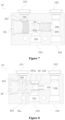
- Figure 1 is a schematic view showing the structure of a thermostatic valve according to a first embodiment of the present application
- Figure 2 is a schematic view of the thermostatic valve in Figure 1 viewed at another angle, showing the bottom
- Figure 3 is a sectional view of the thermostatic valve in Figure 1 , with a second valve port closed and a first valve port opened
- Figure 4 is a schematic view of the thermostatic valve in Figure 3 after a valve core is moved to the right, with the first valve port closed and the second valve port opened
- Figure 5 is a schematic view of a valve body in Figure 3 .
- the thermostatic valve according to the first embodiment includes a valve body 10, and a valve cavity 10a is formed inside the valve body.
- the valve cavity 10a penetrates one end surface of the valve body 10 from left to right, to form the valve cavity 10a with an end port at the left end, and an end cover 30 is used to block the end port.
- a valve core 40 is provided in the valve cavity 10a, and the valve core 40 can move axially along the valve cavity 10a.
- the axial direction here refers to an extending direction of the valve cavity 10a from one end to the other end, which is the left-right direction shown in Figures 3 and 4 .
- the axial direction also refers to the length direction of the valve body 10 or the length direction of the valve cavity 10a.
- the first valve port B is formed in an end cavity wall of the valve cavity 10a, that is, the cavity wall at the right end in Figure 3 , and the left end is the end port blocked by the end cover 30.
- the first valve port B is in communication with the second outlet 104 through the second outlet passage, and the second outlet passage in Figure 3 includes a small hole 10c, and a linear passage 10b between the second inlet 102 and the second outlet 104.
- the lubricating oil After flowing out of the transmission, the lubricating oil enters the thermostatic valve through the first inlet 103, and then the lubricating oil flows directly back to the transmission through the first port B and the second outlet 104, or the lubricating oil enters the cooler through the second port A and the first outlet 101 to be cooled, and returns to the transmission through the second inlet 102 and the second outlet 104.
- the following main working process is also exemplified by this application. However, it can be understood that the transmission and the cooler are only a typical application of the thermostatic valve in the present application. Obviously, besides the transmission, the thermostatic valve can also be applied to other applications that are required to control temperature to adjust the medium flow path.
- the movement of the valve core 40 is mainly achieved by a return spring 202 and a memory spring 201 provided in the valve cavity 10a.
- the memory spring 201 is a spring made of a shape memory alloy material (SMA: Shape Memory Alloy).
- the return spring 202 can provide a return force that causes the valve core 40 to open the first valve port B.
- the return spring 202 is a tension spring, that is, it provides a pulling force.
- the direction of the pulling force of the valve core 40 in Figure 3 is leftward.
- the leftward spring can play the role of connecting the valve core 40.
- the valve core 40 can be processed into a structure with an I-shaped axial cross section as shown in the figure, to reduce weight and facilitate movement.
- the medium (for example, the above lubricating oil of the transmission) flows from the first inlet 103 into the valve cavity 10a of the thermostatic valve. Since the second valve port A is closed and the first valve port B is opened, the medium flows to the small hole 10c, the linear passage 10b, and the second outlet 104 through the first valve port B, and returns to the transmission.
- the medium for example, the above lubricating oil of the transmission
- the thermostatic valve When the medium temperature rises to a specified value, the thermostatic valve is in the working state shown in Figure 4 , the elastic characteristic of the memory spring 201 is activated, and the elastic force generated is greater than the return force of the return spring 202. At this time, the valve core 40 moves toward the first valve port B under a difference between forces applied by the memory spring 201 and the return spring 202. The valve core 40 can block the first valve port B and open the second valve port A. After the medium flows in from the first inlet 103, the medium enters the cooler through the second valve port A, the outlet passage 10d, and the first outlet 101, to be cooled. The cooled lubricating oil flows out of the cooler, and then enters the valve cavity 10a from the second inlet 102, and re-enters the transmission through the linear passage 10b and the second outlet 104.
- the elastic characteristic of the memory spring 201 fails, the elastic force decreases and then disappears, and the valve core 40 moves away from the first valve port B under the return force of the return spring 202, and at this time, the first valve port B is opened, the second valve port A is closed and the valve core 40 returns to the state shown in Figure 3 .
- the memory spring 201 serves as a thermal actuator that drives the action of the valve core 40, and the structure is simple.
- the memory spring 201 and the return spring 202 are both provided between the end cover 30 and the valve core 40.
- the arrangement manner is not limited to this.
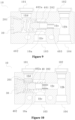
- Figure 6 is a sectional view showing the structure of a thermostatic valve according to a second embodiment of the present application, with the second valve port A closed and the first valve port B opened; and Figure 7 is a schematic view of the thermostatic valve in Figure 6 after the valve core is moved to the right, with the first valve port B closed and the second valve port A opened.
- the memory spring 201 is located between the end cover 30 and the valve core 40.
- the memory spring 201 has one end in contact with another end of the valve core 40, and another end in contact with the end cover 30.
- a stepped hole is formed in the valve body 10, and the large hole of the stepped hole is the valve cavity 10a, and the first valve port B is formed at a junction of the small hole 10c and the large hole.
- the return spring 202 in Figure 6 provides a resilience force instead of a pulling force, that is, the return spring 202 and the memory spring 201 can be respectively provided at two ends of the valve core 40.
- One end of the return spring 202 is in contact with one end of the valve core 40, and the other end of the return spring 202 abuts against the valve body 10 to provide the valve core 40 with a force in the opposite direction.
- the return spring 202 is provided in the small hole 10c, and a step is provided in the small hole 10c.
- the return spring 202 is pre-compressed between the valve core 40 and the step, to provide the resilience force for driving the valve core 40 away from the first valve port B, and the direction of the resilience force is opposite to the direction of the elastic force of the memory spring 201 applied on the valve core 40.
- the right end, facing the return spring 202, of the valve core 40 may be provided with a protrusion to be inserted into the return spring 202, to assemble the return spring 202 and also play a role of positioning and guiding the valve core 40.
- the step may not be provided in the small hole 10c, and the right end of the return spring 202 may directly abut against the inner wall of the linear passage 10b, or a recessed hole is provided in the inner wall of the linear passage 10b, and the right end of the return spring 202 directly abuts against the recessed hole.
- the return spring 202 can also be pre-compressed between the valve core 40 and the cavity wall of the right end portion of the valve cavity 10a.
- the memory spring 201 When the memory spring 201 is heated up and expands, the memory spring 201 deforms and stretches, the diameter of the memory spring 201 decreases, and a gap appears between the second valve port A and the memory spring 201, and a notch may also appear between several spring coils of the memory spring 201, and the medium in the valve cavity 10a may flow through the gap and the notch to the second valve port A and then flow out. At this time, the second valve port A is opened. It can be seen that, with this arrangement, the memory spring 201 not only serves as a thermal actuator that drives the movement of the valve core 40, but also serves as a sealing portion, thereby simplifying the structure of the valve core 40.
- Figure 8 is a sectional view showing the structure of a thermostatic valve in an initial state according to a third example not according to the claims, with a first valve port B having a preset opening degree and a second valve port A having a preset opening degree;
- Figure 9 is a schematic view of the thermostatic valve in Figure 8 after the temperature rises to a specified value and the memory spring 201 is deformed, with the first valve port B closed and the second valve port A opened;
- Figure 10 is a schematic view of the thermostatic valve in Figure 9 after the temperature drops below a specified value and the memory spring 201 loses characteristics, with the first valve port B opened and the second valve port A closed;
- Figure 11 is a schematic view showing the structure of the valve core 40 in Figure 8 .
- the second valve port A is also provided in the side cavity wall of the valve cavity 10a
- the first valve port B is provided in the end cavity wall of the valve cavity 10a
- the valve core 40 in this example is additionally provided with a sleeve portion 402, and the memory spring 201 is provided in the sleeve portion 402 and located between the end cover 30 and the valve core 40.
- the right end of the valve core 40 forms a first sealing portion for blocking the first valve port B
- the sleeve portion 402 on the valve core 40 forms a second sealing portion for blocking the second valve port A.
- the outer wall of the sleeve portion 402 can slide along the side cavity wall of the valve cavity 10a, to block or open the second valve port A.
- the memory spring 201 only serves as a thermal actuator that drives the valve core 40 to move according to temperature changes.
- a protruding platform is provided on the inner end surface of the end cover 30 facing the valve core 40, and one end of the memory spring 201 is sleeved on the protruding platform.
- the valve core 40 includes a main body portion 401 extending in the axial direction and a sleeve portion 402 sleeved outside a part of the main body portion 401.
- the left end of the main body portion 401 extends into the sleeve portion 402.
- Another end of the memory spring 201 is sleeved on the left end of the main body portion 401.
- the sleeve portion 402 and the main body portion 401 of the valve core 40 may be separately processed or integrally formed, as shown in Figure 11 .
- a stepped hole is also formed in the valve body 10.
- the large hole of the stepped hole is the valve cavity 10a, and the first valve port B is formed at the junction of the large hole of the stepped hole and the small hole 10c.
- the right end of the main body portion 401 of the valve core 40 serves as a first sealing portion and is also connected to a guide rod 403.
- the guide rod 403 and the main body portion 401 may be individually formed or integrally formed.
- the guide rod 403 can be inserted into the small hole 10c to guide the movement of the valve core 40.
- the feature that the guide rod 403 is provided on the valve core 40 to be inserted into the small hole 10c for guiding is also applicable to other embodiments.
- the end of the valve core 40 facing the first valve port B may be hollow, to reduce weight and save material.
- the right end of the valve core 40 is provided with a protruding platform to be inserted into the return spring 202.
- the return spring 202 is located in the small hole 10c, and can also play a certain guiding role; however, in the third example, the guide rod 403 is directly inserted into the small hole 10c for guiding, and the guiding effect is better. Since the sleeve portion 402 is provided, the step is not required to be processed on the hole wall of the small hole 10c to install the return spring 202.
- the return spring 202 can be arrange between the sleeve portion 402 and the end cavity wall of the valve cavity 10a, as shown in Figure 8 .
- valve core 40 is provided with the sleeve portion 402
- the sleeve portion 402 is in sliding fit with the side cavity wall of the valve cavity 10a, and an opening 402b is provided at the bottom of the sleeve portion 402 close to the first inlet 103, as shown in Figure 11 (that is, below the bottom in Figure 8 ), so that the medium can flow into the inner cavity of the sleeve portion 402 and thus flows to the second valve port A.
- a guiding inlet 402a penetrating the bottom is further provided at the bottom of the sleeve portion 402 away from the first inlet 103 (above the bottom in Figure 8 ) in Figure 8 , and as a flow guiding passage, the guiding inlet 402 is configured to communicate the valve cavity 10a with the inner cavity of the sleeve portion 402.
- the number of the guiding inlet 402a may be one or more.
- an end protruding platform 401a is provided at the left end of the main body portion 401 of the valve core 40.
- one end of the memory spring 201 is surrounded around the end protruding platform 401a, abuts against the stepped surface formed by the end protruding platform 401a and the main body portion 401, which is the initial position of the end of the memory spring 201.
- the first valve port B is not fully opened and has a preset opening degree
- the second valve port A also has an initial preset opening degree, so that the thermostatic valve has the characteristic of the second valve port A being always open in the initial state, thereby facilitating filling the lubricating oil into the transmission and at the same time filling the lubricating oil into the cooler in the initial state, to meet the requirement of the initial filling. That is, both valve ports are opened.
- the memory spring 201 deforms and expands to a certain extent, thereby detaching from the end protruding platform 401a and surrounding the main body portion 401 with a greater outer diameter.
- the memory spring 201 is then switched to a normal working state, and always surrounds the main body portion 401, as shown in Figure 9 , and is deformed to abut against the bottom position of the sleeve portion 402. This position is the working position.
- the first valve port B is kept closed under the elastic force of the memory spring 201.
- the initial position and working position of the end of the memory spring 201 described in the present application refer to the relative position of the end and the valve body 10 (the cavity wall of the valve cavity or the end cover 30 of the valve body 10) or the relative position of the end and the valve core 40, and do not change as the valve core 40 moves.
- the memory spring 201 When the temperature is lower than a specified value, the memory spring 201 loses its characteristic. Under the action of the return force of the return spring 202, the valve core 40 moves and compresses the memory spring 201. The distance between the bottom of the sleeve portion 402 and the end cover 30 is greater than the distance between the protruding platform of the main body portion 401 and the end cover 30, thus when the memory spring 201 detaches from the protruding platform of the main body portion 401 and surrounds the main body portion 401, the valve core 40 is closer to the end cover 30 under the action of the return spring 202, and the sleeve portion 402 will block the second valve port A, eliminating the initial preset opening degree, as shown in Figure 10 .
- a setting method is provided according to this example, that is, a two-stage step (a stepped surface between the end protruding platform 401a and the main body portion 401 is a first stepped surface, and the bottom of the sleeve portion 402 is a second stepped surface) is provided on the valve core 40, and the initial position and the working position are respectively formed by the first stepped surface and second stepped surface.
- the first valve port B When the memory spring 201 is at the initial position, the first valve port B has a preset opening degree, and the distance between the valve core 40 and the first valve port B when the memory spring 201 is at the initial position is smaller than the distance between the valve core 40 and the first valve port B when the memory spring 201 is at the working position and the temperature is below a specified value.
- the distance between the initial position and the end cover 40 is smaller than the distance between the working position and the end cover 40.
- the first valve port B maintains in a closed state
- the second valve port A has a preset opening degree (if the second valve port A is not provided, the medium can flow directly to the first outlet 104).
- the distance between the end cover 30 and the valve core 40 becomes longer, so that the return spring 202 can drive the valve core 40 to compress the memory spring 202 by more distance, thereby opening the first valve port B and closing the second valve port A.
- the setting of the initial position and the working position is to adjust the distance between the valve core 40 and the end cover 30 or the valve core 40 and the valve body 10, so that the distance between the two ends of the memory spring 201 can be compressed to different degrees at the two working positions, thereby achieving the opening and closing of the first valve port B. Therefore, the initial position and the working position can also be set at the valve core 40 or the valve body 10, which can also be achieved by the two-stage step method, and both the valve core 40 and the valve body 10 can be set with the initial position and the working position, or both the valve core 40 and the end cover 30 can be set with the initial position and the working position, so that both ends of the memory spring 201 can abut against the initial position or the working position.
- the inlets, outlets, and valve ports of the thermostatic valve can also be set by other ways.
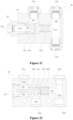
- Figure 12 is a sectional view showing the structure of a thermostatic valve in an initial state according to a forth example of the present application, with a first valve port B having a preset opening degree and a second valve port A having a preset opening degree;
- Figure 13 is a schematic view of the thermostatic valve in Figure 12 after the temperature rises to a specified value and the memory spring 201 is deformed, with the first valve port B closed and the second valve port A opened;
- Figure 14 is a schematic view of the thermostatic valve in Figure 13 after the temperature drops below a specified value and the memory spring 201 loses characteristics, with the first valve port B opened and the second valve port A closed;
- Figure 15 is a schematic view showing the structure of the end cover 30 in Figure 12 .
- the end cover 30 actually not only covers the end port position of the valve body 10, but also becomes a seat switching structure to function as a connector for communicating with the outside, specifically for communicating with the cooler in this example.
- the switching seat is provided with a passage penetrating the inside and outside of the switching seat, and an outlet passage 10d is formed by the passage.
- the internal end port of the outlet passage 10d is the second valve port A, and the external end port is the first outlet 101.
- the second valve port A and the first valve port B are distributed along the axial direction of the valve cavity 10a.
- one end of the valve core 40 may be a first sealing portion for blocking the first valve port B, and the other end is a second sealing portion for blocking the second valve port A.
- the operation is more convenient for the valve core 40 to block the first valve port B and the second valve port A, and the valve core 40 is easier to process.
- the second outlet 104, the second inlet 102, and the first inlet 103 are also formed by connectors 50 externally connected to the valve body 10.
- the outlets and inlets in communication with the outside are each directly formed as a connector-like structure on the valve body 10, and both solutions are applicable to all embodiments and examples of the present solution.
- the setting of the initial preset opening degree is also performed.
- a two-stage step is provided at the inner end, toward the valve core 40, of the switching seat, and the outer diameter of the first step is smaller than the outer diameter of the second step, forming a first step surface 301 and a second step surface 302 that both face the valve core 40, the first step surface 301 is the initial position and the second step surface 302 is the working position.
- the distance between the valve core 40 and the initial position is smaller than the distance between the valve core 40 and the working position.
- the left end of the memory spring 201 is surrounded around the first step of the valve core 40 and abuts against the first step surface 301.
- the first valve port B is closed and the second valve port A has the initial preset opening degree, as shown in Figure 12 , so that the thermostatic valve has the characteristic of the second valve port A being always open in the initial state, thereby facilitating filling the lubricating oil into the transmission in the initial state and at the same time filling the lubricating oil into the cooler, to meet the requirement of the initial filling.
- the second valve port A is not provided, the memory spring 201 abuts against the initial position, the first valve port B is closed, and the lubricating oil can directly flow into the cooler through the first outlet 101.
- the memory spring 201 deforms and expands to a certain extent, thereby detaching from the first step and surrounding around the second step. After that, the memory spring 201 is switched to the normal working position and will be always surrounded around the second step, as shown in Figure 13 . The memory spring 201 is also deformed to abut against the second step surface 302. At this time, the first valve port B is kept closed under the elastic force of the memory spring 201.
- the memory spring 201 When the temperature is lower than a specified value, the memory spring 201 loses its characteristic. Under the action of the return force of the return spring 202, the valve core 40 moves and compresses the memory spring 201. The distance between the second step surface 302 and the valve core 40 is greater than the distance between the first step surface 301 and the valve core 40, thus when the memory spring 201 is detached from the first step and surrounded around the second step, the valve core 40 will be closer to the end cover 30 under the action of the return spring 202, and the left end portion of the valve core 40 will block the second valve port A, eliminating the initial preset opening degree, and the first valve port B is now open.
- the outer periphery of the end (the left end portion in Figure 12 , that is, the second sealing portion), facing the second valve port A, of the valve core 40 is tapered, that is, having a tapered surface that cooperates with the second valve port A, in order to better block the second valve port A and have a guiding effect.
- the left end portion of the valve core 40 is also provided with a peripheral protrusion as shown in Figure 12 , the right end of the memory spring 201 abuts against the peripheral protrusion.
- the end (the right end portion in Figure 12 , that is, the first sealing portion), facing the first valve port B, of the valve core 40 has a protruding platform and the protruding platform can be inserted into the return spring 202.
- the return spring 202 is placed in the small hole 10c.
- the valve core 40 may also have other structures, as shown in Figures 16 to 17 .
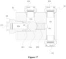
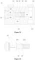
- Figure 16 is a sectional view showing the structure of a thermostatic valve in an initial state according to a fifth example of the present application, with a first valve port B having a preset opening degree and a second valve port A having a preset opening degree; and
- Figure 17 is a schematic view of the thermostatic valve in Figure 16 after the temperature rises to a specified value and the memory spring 201 is deformed, with the first valve port B closed and the second valve port A opened.
- valve core 40 is a spherical body.
- the spherical valve core 40 may also be used, or at least the portion for blocking is processed into a spherical surface.
- a two-stage step is also provided on the end cover 30 with the seat switching structure, so that the memory spring 201 has an initial shape and forms an initial preset opening degree, which facilitates to filling the cooling oil into the cooler.
- Figure 19 is a sectional view showing the structure of a thermostatic valve according to a sixth example of the present application, with a first valve port B closed and a second valve port A opened; and Figure 20 is a schematic view showing the structure of the valve core 40 in Figure 19 .
- valve core 40 includes a spherical portion 404 and a sealing plate 405 connected to each other.
- the spherical portion 404 is used to block the second valve port A
- the sealing plate 405 is used to block the first valve port B.
- a recessed hole 405a is provided in the side of the sealing plate 405 facing the spherical portion 404, so that the spherical portion 404 can be partially inserted into the recessed hole 405a to be fixed, thereby facilitating the fixation of the spherical portion 404 and the sealing plate 405.
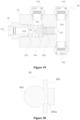
- Figure 21 is a sectional view showing the structure of a thermostatic valve according to a seventh example of the present application, with a first valve port B closed and a second valve port A opened.
- valve core 40 is cylindrical in this example, and two end surfaces of the valve core 40 are used to seal the first valve port B and the second valve port A, respectively.
- a protrusion is also provided on the side of the valve core 40 facing the first valve port B, to be inserted into the return spring 202, which has functions of positioning, guiding and facilitating the installation of the return spring 202.
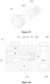
- Figure 22 is a sectional view showing the structure of a thermostatic valve according to an eighth example of the present application, with a first valve port B opened and a second valve port A closed;
- Figure 23 is a schematic view of the thermostatic valve after the temperature rises and the memory spring 201 is deformed in Figure 22 , with the first valve port B closed and the second valve port A opened;
- Figure 24 is a schematic view of the end cover 30 and the valve core 40, the return spring 202, and the memory spring 201 in Figure 22 after installation;
- Figure 25 is a schematic perspective view of Figure 24 .
- the second valve port A in this example is also provided in the end cover 30 (the end cover is not embodied as the seat switching structure), but the first outlet 101 is still provided in the side wall of the valve body 10.
- an outlet passage 10d communicating the first outlet 101 with the second valve port A is provided in the end cover 30 and the valve body 10, and the outlet passage 10d is actually equivalent to an "L" shape, as shown in Figure 22 .
- the position of the second valve port A is similar to that of the fourth to seventh examples, which allows the valve core 40 to more conveniently move to realize blocking.
- the end cover 30 is provided with a hole
- the thermostatic valve is further provided with a valve stem 60.
- One end of the valve stem 60 can be inserted into the hole along the axial direction to be fixed, and another end of the valve stem 60 extends out of the end cover 30.
- the other end of the valve stem 60 extending out of the end cover 30 can be inserted into the valve core 40 and is in sliding fit with the valve core 40. In this way, the valve core 40 can move along the valve stem 60 during the movement process, thereby having good positioning and guiding effects.
- an annular passage is formed at the outer periphery of the end cover 30, which facilitates the medium flowing to the first outlet 101.
- the left end portion of the end cover 30 is used to block the left end port of the valve cavity 10a
- the second valve port A is formed at the right end portion
- a connector is provided between the left end portion and the right end portion.
- the valve stem 60 is inserted into the connector from the second valve port A and enters the left end portion.
- the left end portion, the right end portion, and the connector of the end cover 30 are integrally formed, so that the structure is reliable, achieving the reliable installation of the valve stem 60 and the memory spring 201, and these members can be assembled first and then installed into the valve cover 10a.
- the left end portion, the right end portion, and the connector of the end cover 30 may also be formed separately and then connected.
- valve stem 60 is also applicable to other embodiments and examples.
- the valve stem can be inserted into the passage of the end cover 30, and the end portion of the valve stem can be fixed to the side wall of the passage by a connector.
- valve stem 60 is fixed to the end cover 30. It can be understood that the valve stem 60 can also be fixed to the valve core 40 and in sliding fit with the end cover 30. In comparison, in case that the valve stem 60 is fixed to the end cover 30, the valve core 40 can operate more smoothly and reliably.
- valve core 40 may be provided with a through hole to facilitate sliding along the valve stem 60.
- a sealing piece 40' is provided on the outer peripheral wall of the right end of the valve core 40.
- the sealing piece 40' serves as a first sealing portion for blocking the first valve port B.
- an annular groove is further provided in the outer peripheral wall of the right end of the valve core 40.
- One end of the return spring 202 is inserted in the annular groove, another end of the return spring 202 abuts against the step of the small hole 10c, of course, the another end of the return spring 202 can also abut against the inner wall of the linear passage 10b or the end cavity wall of the valve cavity 10a, which has been described in the above examples, and will not be repeated here.
- the sealing piece 40' can also be integrally formed with the valve core 40.
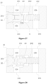
- Figure 26 is a sectional view showing the structure of a thermostatic valve according to a ninth example of the present application, with a first valve port B closed and a second valve port A opened.
- the return spring 202 can directly abut against the sealing piece 40'.
- the return spring 202 shown in Figure 25 is pre-compressed on the step of the small hole 10c and the sealing piece 40'.
- the valve core 40 can be variously designed in each embodiment of the present application, and the structure of the valve core 40 in each embodiment can be used interchangeably.
- valve core 40 when the first inlet 103 is provided in the side wall of the valve body 10, in order to improve the reliability of the movement of the valve core 40, the valve core 40 may be designed such that at least a portion of the valve core 40 is in sliding fit with the inner wall of the valve cavity 40, which can prevent impact on the valve core 40 or the memory spring 201 when the fluid flows in.
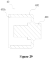
- Figure 27 is a sectional view showing the structure of a thermostatic valve according to a tenth example of the present application, with a first valve port B opened and a second valve port A closed;
- Figure 28 is a schematic view of the thermostatic valve in Figure 27 after the valve core is moved to the right, with the second valve port A opened and the first valve port B closed;
- Figure 29 is a schematic view of the valve core 40 in Figure 27 .
- the valve core 40 is movable axially along the valve cavity 10a, and a portion of the valve core 40 is in sliding fit with the inner wall of the valve cavity 10a.
- the first valve port B is located at the end cavity wall of the valve cavity 10a, that is, the axial cavity wall
- the second valve port A is located at the side cavity wall of the valve cavity 10a, that is, the radial cavity wall.
- the first inlet 103 and the second valve port A are opposite to each other.
- the inlet passage 10e communicating the first inlet 103 with the valve cavity 10a is opposite to the second valve port A and the outlet passage 10d.
- the passage between the first inlet 103 and the first outlet 101 is the linear passage.
- the second valve port A when the second valve port A is opened, the medium can flow out through the linear passage, and the response is faster.
- the structure of the valve core 40 in this example is similar to that in the third example.
- the valve core 40 includes a sleeve portion 402 acting as a second sealing portion for blocking the second valve port A.
- the memory spring 201 is provided in the sleeve portion 402 and is located between the valve core 40 and the end cover 30.
- a notch 402c is provided at an edge of the open end of the sleeve portion 402, to function as a flow guiding passage for guiding a medium into the sleeve portion 402.
- the flow guiding passage is not limited to the notch 402c shown in the figure, for example, it may also be provided in the side wall or the bottom of the sleeve portion 402.
- outlet passage 10d and the inlet passage 10e in this embodiment are oppositely arranged.
- a part of the outer wall of the sleeve portion 402 corresponding to the second valve port A is in sliding fit with the inner wall of the valve cavity 10a, and a gap is provided between the part, corresponding to the inlet passage 10e and the first inlet 103, of the outer wall of the sleeve portion 402 and the inner wall of the valve cavity 10a, which can ensure that the medium can flow to the first valve port B.
- the second sealing portion is only required to seal the second valve port A, and a gap is required to be provided between the portion, facing the inlet passage 10e, of the sleeve portion 402 and the inner wall of the valve cavity 10a.
- the central axis of the valve cavity 10a is offset from the central axis of the valve core 40, and the portion, opposite to the inlet passage 10e, of the valve cavity 10a is concave.
- the valve cavity 10a may not be concave, and the valve core 40 may be provided as an eccentric structure relative to the axis. This manner of a portion of the valve core 40 in sliding fit with the inner wall of the valve cavity 10a not only satisfies stability and impact resistance, but also facilitates fluid flow
- a two-stage stepped hole is formed in the valve body 10 of the thermostatic valve, the largest hole is the valve cavity 10a, and a first valve port B is formed at a junction between the middle hole and the largest hole.
- the stroke of the valve core 40 moving to block the first valve port B can be shortened.
- the second inlet 102 and the second outlet 104 in this example are also opposite to each other, and a linear passage 10b is formed between the second inlet 102 and the second outlet 104, and the return spring 202 penetrates the smallest hole and is compressed between the valve core 40 and the inner wall of the linear passage 10b.
- a groove allowing the end portion of the return spring 202 to be inserted can be provided in the inner wall of the linear passage 10b.
- the end portion of the return spring 202 may also be compressed on the end wall of the valve cavity 10a, or a step may be provided at the smallest hole, and the end portion of the return spring 202 can be compressed on the step or the valve core 40.
- the formed valve cavity 10a is a cavity with an end port at one end, an end cover 30 is provided at the end port, and the memory spring 201 is provided between the end cover 30 and the valve core 40.
- This method is convenient for machining the valve body 10 to form the valve cavity 10a, but it can be understood that the structure of the valve cavity 10a is not limited thereto.
- two ends of the valve cavity 10a may not have end ports, and no end covers are provided.
- the memory spring 201 and the return spring 202 (in the first embodiment) may be provided between the cavity wall of the valve cavity 10a and the valve core 40.
- the purpose of setting the two-stage step is to use the characteristic of the memory spring 201, to allow the memory spring 201 to switch from the initial position to the working position after being heated, expanded and deformed, and to be kept at the working position. Therefore, the solutions for realizing the purpose is not limited to providing the two-stage step.
- an annular groove is provided at the end portion of the valve core 40, and an end portion of the memory spring 201 is provided in the annular groove, and after the temperature rises, this end portion of the memory spring 201 is detached from the annular groove and abuts against other position as the working position, which can also achieve the purpose of setting the initial preset opening degree.
- the control element for controlling the movement of the valve core 40 of the thermostatic valve is the memory spring 201.
- the response time of the memory spring 201 is faster, and the second valve port A can be opened in time to switch the medium to another flow path.
- a thermal actuator is not required to be additionally provided in the thermostatic valve, the structure is simple and the installation is convenient, which allows the whole thermostatic valve lighter in weight and smaller in volume.
- valve body 10 is provided with the first valve port B and the second valve port A. It can be understood that the second valve port A may not be provided, that is the second valve port A that can be opened and closed is not provided, but the passage between the first outlet 101 and the valve cavity 10a is through.
- the medium (such as lubricating oil) can directly flow to the cooler; when the first valve port B is opened, even if there is no second valve port A and only the outlet passage in communication with the first outlet 101 is provided, because the cooler is in communication with the first outlet 101, the flow resistance of the flow path through the first outlet 101 will be greater than the flow resistance of the flow path directly flowing to the second outlet 104 through the first valve port B. Therefore, the medium will mostly flow through the first valve port B to the second outlet 104.
- the second valve port A and switching the opening and closing states of the second valve port A and the first valve port B it can more clearly distribute the flow paths of the medium under different requirements and reduce the system internal leakage.
- the second valve port A when the second valve port A is not provided, in the above embodiment with the initial position and working position, it can be designed in a way that when the memory spring 201 is at the initial position, the first valve port B is closed, so that the lubricating oil can be directly flows into the cooler from the first outlet 101 to fill the lubricating oil in the initial state.
- a second inlet 102 should be provided, and the first valve port B will also be in communication with the second inlet 102, so that the lubricating oil flowing in from the second inlet 102 can also fill the passage between the first valve port B and the transmission, to complete the oil filling process of the whole system.
- the first valve port B may have a preset opening degree as described in the above embodiment, and may also be closed.
- the valve body 10 of the thermostatic valve is also preferably provided with the second inlet 102 in communication with the second outlet 104, so that the lubricating oil flowing in from the second inlet 102 can also fill the passage between the first valve port B and the transmission.
- the first valve port B has a preset opening degree at the initial position, the passage between the first valve port B and the transmission can be filled.
- the solution is not limited to providing the second inlet 102 in the valve body 10, and the outlet of the cooler can also be connected to the transmission through other passages.
- the second valve port A in order to facilitate filling the cooler in the initial state, it can be set as follows: a distance between the valve core 40 and the first valve port B when the memory spring 201 is at the initial position is smaller than the distance between the valve core 40 and the first valve port B when the memory spring is at the working position and the temperature is below a specified value. In this way, when the memory spring 201 is below the temperature with the specified value, the length of the memory spring 201 changes, so that the first valve port B and/or the second valve port A can be adjusted to have different opening degrees at the initial position and working position.
Landscapes
- Engineering & Computer Science (AREA)
- General Engineering & Computer Science (AREA)
- Mechanical Engineering (AREA)
- Physics & Mathematics (AREA)
- General Physics & Mathematics (AREA)
- Automation & Control Theory (AREA)
- Chemical & Material Sciences (AREA)
- Combustion & Propulsion (AREA)
- Temperature-Responsive Valves (AREA)
Claims (7)
- Thermostatventil umfassend eine Endabdeckung (30), einen Ventilkörper (10) und einen Ventilkern (40), der sich in einem Ventilhohlraum (10a) des Ventilkörpers (10) befindet, wobei das Thermostatventil einen ersten Auslass (101), einen zweiten Auslass (104) und einen ersten Einlass (103) aufweist, der mit dem Ventilhohlraum (10a) in Verbindung steht, der Ventilkörper (10) ferner mit einer ersten Ventilöffnung (B) versehen ist, die dazu ausgebildet ist, den Ventilhohlraum (1 0a) mit dem zweiten Auslass (104) in Verbindung zu bringen, und der Ventilkern (40) dazu ausgebildet ist, während einer Bewegung des Ventilkerns (40), die erste Ventilöffnung (B) zu öffnen oder zu schließen; wobeieine Rückstellfeder (202) und eine Memoryfeder (201) ferner in dem Ventilhohlraum (10a) vorgesehen sind, wobei die Memoryfeder (201) aus einer Memory-Legierung besteht; wobei die Rückstellfeder (202) dazu ausgebildet ist, eine Rückstellkraft bereitzustellen, damit der Ventilkern (40) die erste Ventilöffnung (B) öffnen kann; wobei die Memoryfeder (201) mit einem Ende mit einem Ende des Ventilkerns (40) in Kontakt steht und mit einem anderen Ende mit der Endabdeckung (30) in Kontakt steht, und wenn eine Temperatur auf einen vorgegebenen Wert ansteigt, die Memoryfeder (201) dazu ausgebildet ist, eine elastische Kraft zu erzeugen, um den Ventilkern (40) gegen die Rückstellkraft zu bewegen, um die erste Ventilöffnung (B) zu schließen; undder erste Einlass (103) in einer Seitenwand des Ventilkörpers (10) vorgesehen ist, wobei das Thermostatventil dadurch gekennzeichnet ist, dass es ferner mit einer zweiten Ventilöffnung (A) versehen ist, die zweite Ventilöffnung (A) in einer Seitenwand des Ventilhohlraums (10a) vorgesehen ist und, wenn die Temperatur niedriger ist als der vorgegebene Wert, die Memoryfeder (201) sich in einem komprimierten und gespannten Zustand und in Übereinstimmung mit der Position der zweiten Ventilöffnung (A) befindet, um die zweite Ventilöffnung (A) zu blockieren, wobei die zweite Ventilöffnung (A) dazu dient, den Ventilhohlraum (10a) mit dem ersten Auslass (101) in Verbindung zu bringen.
- Thermostatventil nach Anspruch 1, wobei der Ventilkern (40) oder die Endabdeckung (30) mit einer Anfangsposition und einer Arbeitsposition versehen ist, und wenigstens ein Ende der Memoryfeder (201) sich in der Anfangsposition der Endabdeckung (30) oder der Anfangsposition des Ventilkerns (40) befindet, und wenn sich die Memoryfeder (201) in der Anfangsposition befindet, sich die erste Ventilöffnung (B) in einem geschlossenen Zustand befindet, die zweite Ventilöffnung (A) sich in einem geöffneten Zustand befindet, und die zweite Ventilöffnung (A) einen voreingestellten Öffnungsgrad aufweist; nachdem die Temperatur der Memoryfeder (201) auf den vorgegebenen Wert gestiegen ist und die Memoryfeder (201) verformt ist, ein Endabschnitt der Memoryfeder dazu ausgebildet ist, sich von der Anfangsposition zu lösen, um die Arbeitsposition einzunehmen und in der Arbeitsposition gehalten zu werden; und
wenn die Temperatur in der Arbeitsposition auf den vorgegebenen Wert ansteigt, die Memoryfeder (201) dazu ausgebildet ist, die elastische Kraft zu erzeugen, um den Ventilkern (40) gegen die Rückstellkraft zu bewegen, um die erste Ventilöffnung (B) zu schließen; und nachdem die Temperatur der Memoryfeder (201) unter den vorgegebenen Wert gefallen ist, die Memoryfeder (201) ihre elastischen Eigenschaften verliert, und die Rückstellfeder (202) dazu ausgebildet ist, den Ventilkern (40) anzutreiben, um die erste Ventilöffnung (B) zu öffnen. - Thermostatventil nach Anspruch 2, wobei die Endabdeckung (30) mit einer zweistufigen Stufe versehen ist, umfassend eine erste Stufe und eine zweite Stufe mit einem Außendurchmesser größer als ein Außendurchmesser der ersten Stufe, wobei eine Position einer Oberfläche der ersten Stufe die Anfangsposition ist, eine Position einer Oberfläche der zweiten Stufe die Arbeitsposition ist und ein Abstand zwischen der Anfangsposition und der ersten Ventilöffnung (B) kleiner ist als ein Abstand zwischen der Arbeitsposition und der ersten Ventilöffnung (B).
- Thermostatventil nach Anspruch 2 oder 3, wobei das Thermostatventil ferner einen zweiten Einlass (102) umfasst, der mit dem zweiten Auslass (104) in Verbindung steht, und der erste Auslass (101), der zweite Einlass (102), der zweite Auslass (104) und der erste Einlass (103) alle in der Seitenwand des Ventilkörpers (10) vorgesehen sind; und der zweite Auslass (104) und der zweite Einlass (102) einander gegenüberliegen, ein linearer Durchgang (10b) zwischen dem zweiten Auslass (104) und dem zweiten Einlass (102) gebildet ist, und die erste Ventilöffnung (B) mit dem linearen Durchgang (10b) in Verbindung steht.
- Thermostatventil nach Anspruch 2 oder 3, wobei das Thermostatventil ferner einen zweiten Einlass (102) umfasst, der mit dem zweiten Auslass (104) in Verbindung steht, und der erste Auslass (101) und der zweite Einlass (102) jeweils mit einem Einlass und einem Auslass eines Kühlers verbunden sind; und der erste Einlass (103) und der zweite Auslass (104) jeweils mit einem Einlass und einem Auslass eines Getriebes verbunden sind.
- Thermostatventil nach Anspruch 4 oder 5, wobei eine Stufenbohrung in dem Ventilkörper (10) ausgebildet ist, ein großes Loch der Stufenbohrung den Ventilhohlraum (10a) darstellt, und die erste Ventilöffnung (B) an einem Übergang zwischen dem großen Loch und einem kleinen Loch (10c) der Stufenbohrung ausgebildet ist; eine Führungsstange (403) mit dem ersten Dichtungsabschnitt verbunden ist, wobei die Führungsstange in das kleine Loch (10c) eingesetzt ist und mit einer Innenwand des kleinen Loches (10c) in Gleitsitz steht, um die Bewegung des Ventilkerns (40) zu führen.
- Thermostatventil nach Anspruch 1, wobei das Thermostatventil einen zweiten Einlass (102) aufweist, der mit dem zweiten Auslass (104) in Verbindung steht,wobei wenigstens eines von dem Ventilkörper (10), dem Ventilkern (40) und der Endabdeckung (30) mit einer Anfangsposition und einer Arbeitsposition versehen ist, und wenigstens ein Endabschnitt der Memoryfeder (201) sich in der Anfangsposition des Ventilkörpers (10) oder des Ventilkerns (40) oder der Endabdeckung (30) befindet; und nachdem eine Temperatur der Memoryfeder (201) auf einen vorgegebenen Wert gestiegen ist und die Memoryfeder (201) verformt ist, der Endabschnitt der Memoryfeder (201) dazu ausgebildet ist, sich aus der Anfangsposition zu lösen und in der Arbeitsposition gehalten zu werden;wenn sich die Memoryfeder (201) in der Anfangsposition befindet, die erste Ventilöffnung (B) geschlossen ist; und wenn sich die Memoryfeder (201) in der Anfangsposition befindet, ein Abstand zwischen dem Ventilkern (40) und der ersten Ventilöffnung (B) kleiner als ein Abstand zwischen dem Ventilkern (40) und der ersten Ventilöffnung (B) ist, wenn sich die Memoryfeder (201) in der Arbeitsposition befindet und die Temperatur unter einem vorgegebenen Wert liegt; undwenn sich die Memoryfeder (201) in der Arbeitsposition befindet und die Temperatur auf den vorgegebenen Wert ansteigt, die Memoryfeder (201) dazu ausgebildet ist, die elastische Kraft zu erzeugen, um den Ventilkern (40) gegen die Rückstellkraft in zu bewegen, um die erste Ventilöffnung (B) zu schließen; und nachdem die Temperatur der Memoryfeder (201) unter den vorgegebenen Wert gefallen ist, die Memoryfeder (201) ihre elastischen Eigenschaften verliert, und die Rückstellfeder (202) dazu ausgebildet ist, den Ventilkern (40) anzutreiben, um die erste Ventilöffnung (B) zu öffnen.
Applications Claiming Priority (3)
| Application Number | Priority Date | Filing Date | Title |
|---|---|---|---|
| CN201711116965.7A CN109780260B (zh) | 2017-11-13 | 2017-11-13 | 调温阀 |
| CN201711115307.6A CN109780259B (zh) | 2017-11-13 | 2017-11-13 | 调温阀 |
| PCT/CN2018/115136 WO2019091481A1 (zh) | 2017-11-13 | 2018-11-13 | 调温阀 |
Publications (3)
| Publication Number | Publication Date |
|---|---|
| EP3712466A1 EP3712466A1 (de) | 2020-09-23 |
| EP3712466A4 EP3712466A4 (de) | 2021-07-14 |
| EP3712466B1 true EP3712466B1 (de) | 2025-01-08 |
Family
ID=66437590
Family Applications (1)
| Application Number | Title | Priority Date | Filing Date |
|---|---|---|---|
| EP18877273.5A Active EP3712466B1 (de) | 2017-11-13 | 2018-11-13 | Thermostatventil |
Country Status (5)
| Country | Link |
|---|---|
| US (1) | US20200293071A1 (de) |
| EP (1) | EP3712466B1 (de) |
| KR (1) | KR102297792B1 (de) |
| CN (1) | CN110799776B (de) |
| WO (1) | WO2019091481A1 (de) |
Families Citing this family (3)
| Publication number | Priority date | Publication date | Assignee | Title |
|---|---|---|---|---|
| CN109695703B (zh) * | 2017-10-23 | 2021-02-02 | 浙江三花汽车零部件有限公司 | 一种热交换装置 |
| CN112762200A (zh) * | 2021-01-19 | 2021-05-07 | 天地上海采掘装备科技有限公司 | 温度控制阀 |
| CN116624379A (zh) * | 2023-07-11 | 2023-08-22 | 安徽南方化工泵业有限公司 | 一种化工泵用机械密封结构 |
Family Cites Families (20)
| Publication number | Priority date | Publication date | Assignee | Title |
|---|---|---|---|---|
| US4190198A (en) * | 1978-04-12 | 1980-02-26 | Lockhart Industries, Inc. | Oil cooler bypass valve actuating means |
| US5746170A (en) * | 1995-11-16 | 1998-05-05 | Ginko Bussan Co., Ltd. | Engine oil block for use in routing oil to an oil cooler |
| US6497372B2 (en) * | 2000-12-07 | 2002-12-24 | Jae-Heung Lee | Automatic temperature control valve |
| DE10261180A1 (de) * | 2002-12-20 | 2004-07-01 | Daimlerchrysler Ag | Temperaturgeregelte Ölspritzdüse zur Kolbenkühlung |
| US6742716B1 (en) * | 2003-02-28 | 2004-06-01 | Standard-Thomson Corporation | Thermostat |
| DE102006039554A1 (de) * | 2006-08-23 | 2008-03-06 | Zf Friedrichshafen Ag | Bypassventil für einen einem Hydraulikaggregat nachgeordneten Kühler |
| CN102597440A (zh) * | 2009-12-07 | 2012-07-18 | 株式会社Tbk | 发动机润滑油供给装置 |
| KR101108063B1 (ko) * | 2010-01-22 | 2012-01-31 | 김순자 | 형상기억 합금 스프링을 이용한 자동 온도조절 밸브 |
| US8960562B2 (en) * | 2011-08-19 | 2015-02-24 | GM Global Technology Operations LLC | Valve configured for regulating the flow of fluid from a transmission to a fluid cooler |
| CN202360800U (zh) * | 2011-11-24 | 2012-08-01 | 北京龙浩安达新技术有限公司 | 切换阀及采暖系统 |
| CN202371214U (zh) * | 2011-11-24 | 2012-08-08 | 北京龙浩安达新技术有限公司 | 冷热切换混合阀 |
| US9200713B2 (en) * | 2011-12-02 | 2015-12-01 | GM Global Technology Operations LLC | Valve configured for regulating the flow of fluid from a transmission to a cooler |
| CN103791664B (zh) * | 2012-10-31 | 2016-09-14 | 浙江三花股份有限公司 | 一种带有单向控制功能的热力膨胀阀 |
| KR101600405B1 (ko) * | 2013-03-11 | 2016-03-07 | 이재흥 | 형상기억합금 스프링을 이용한 자동온도 조절밸브 |
| US9951858B2 (en) * | 2014-02-14 | 2018-04-24 | GM Global Technology Operations LLC | Thermal bypass valve using shape memory alloys |
| CN104595526B (zh) * | 2015-01-14 | 2017-03-15 | 苏州西脉记忆合金有限公司 | 一种记忆合金恒温水龙头 |
| KR101733466B1 (ko) * | 2015-10-12 | 2017-05-11 | 주식회사 유니크 | 바이패스 밸브와 이를 포함하는 바이패스 밸브 조립체 |
| US20160047459A1 (en) * | 2015-10-30 | 2016-02-18 | Air International Thermal Systems R & D (Shanghai) Co., Ltd | Temperature-regulating Valve of Transmission Oil Cooling System in A Passenger Car |
| CN107304844B (zh) * | 2016-04-21 | 2019-08-23 | 浙江三花汽车零部件有限公司 | 一种调温器及一种温控系统 |
| CN107304834B (zh) * | 2016-04-21 | 2020-06-23 | 浙江三花汽车零部件有限公司 | 一种温控系统 |
-
2018
- 2018-11-13 US US16/761,487 patent/US20200293071A1/en not_active Abandoned
- 2018-11-13 WO PCT/CN2018/115136 patent/WO2019091481A1/zh not_active Ceased
- 2018-11-13 KR KR1020207016769A patent/KR102297792B1/ko active Active
- 2018-11-13 EP EP18877273.5A patent/EP3712466B1/de active Active
- 2018-11-13 CN CN201880040434.0A patent/CN110799776B/zh active Active
Also Published As
| Publication number | Publication date |
|---|---|
| US20200293071A1 (en) | 2020-09-17 |
| KR20200085329A (ko) | 2020-07-14 |
| CN110799776B (zh) | 2024-04-09 |
| WO2019091481A1 (zh) | 2019-05-16 |
| EP3712466A4 (de) | 2021-07-14 |
| CN110799776A (zh) | 2020-02-14 |
| EP3712466A1 (de) | 2020-09-23 |
| KR102297792B1 (ko) | 2021-09-03 |
Similar Documents
| Publication | Publication Date | Title |
|---|---|---|
| EP3467352B1 (de) | Temperaturregelventil | |
| US10054962B2 (en) | Thermo valve | |
| EP3059405B1 (de) | Thermostatventil | |
| KR102380176B1 (ko) | 밸브 조립체, 열교환 조립체, 및 기어박스용 오일온도조절 시스템 | |
| EP3712466B1 (de) | Thermostatventil | |
| KR20200051793A (ko) | 열 교환 장치 | |
| CA2755451A1 (en) | Thermal valve | |
| EP3812633A1 (de) | Temperaturregelungsventil | |
| KR20180111937A (ko) | 서모스탯 및 온도 제어 시스템 | |
| CN109780260B (zh) | 调温阀 | |
| US10302208B2 (en) | Control valve with external relief bias member | |
| KR20190047018A (ko) | 변속기 오일의 온도를 조정하기 위한 시스템, 열 교환 조립체 및 밸브 조립체 | |
| CN108087530B (zh) | 热交换组件 | |
| CN109780258B (zh) | 调温阀 | |
| CN109780259B (zh) | 调温阀 | |
| CN109780261B (zh) | 调温阀 | |
| CN108087532B (zh) | 热交换组件 | |
| CN109780310B (zh) | 调温阀 | |
| CN112747167B (zh) | 一种调温阀 | |
| CN108087531B (zh) | 热交换组件 | |
| CN109780187A (zh) | 调温阀 | |
| CN108087579B (zh) | 阀组件 | |
| JP4812427B2 (ja) | 膨張弁 | |
| RU237103U1 (ru) | Балансировочный клапан | |
| JPH0314111B2 (de) |
Legal Events
| Date | Code | Title | Description |
|---|---|---|---|
| STAA | Information on the status of an ep patent application or granted ep patent |
Free format text: STATUS: THE INTERNATIONAL PUBLICATION HAS BEEN MADE |
|
| PUAI | Public reference made under article 153(3) epc to a published international application that has entered the european phase |
Free format text: ORIGINAL CODE: 0009012 |
|
| STAA | Information on the status of an ep patent application or granted ep patent |
Free format text: STATUS: REQUEST FOR EXAMINATION WAS MADE |
|
| 17P | Request for examination filed |
Effective date: 20200520 |
|
| AK | Designated contracting states |
Kind code of ref document: A1 Designated state(s): AL AT BE BG CH CY CZ DE DK EE ES FI FR GB GR HR HU IE IS IT LI LT LU LV MC MK MT NL NO PL PT RO RS SE SI SK SM TR |
|
| AX | Request for extension of the european patent |
Extension state: BA ME |
|
| DAV | Request for validation of the european patent (deleted) | ||
| DAX | Request for extension of the european patent (deleted) | ||
| A4 | Supplementary search report drawn up and despatched |
Effective date: 20210611 |
|
| RIC1 | Information provided on ipc code assigned before grant |
Ipc: F16H 57/04 20100101AFI20210607BHEP Ipc: F16K 11/02 20060101ALI20210607BHEP Ipc: F01P 7/16 20060101ALN20210607BHEP Ipc: F01P 11/08 20060101ALN20210607BHEP |
|
| STAA | Information on the status of an ep patent application or granted ep patent |
Free format text: STATUS: EXAMINATION IS IN PROGRESS |
|
| 17Q | First examination report despatched |
Effective date: 20230627 |
|
| GRAP | Despatch of communication of intention to grant a patent |
Free format text: ORIGINAL CODE: EPIDOSNIGR1 |
|
| STAA | Information on the status of an ep patent application or granted ep patent |
Free format text: STATUS: GRANT OF PATENT IS INTENDED |
|
| INTG | Intention to grant announced |
Effective date: 20240722 |
|
| P01 | Opt-out of the competence of the unified patent court (upc) registered |
Free format text: CASE NUMBER: APP_48068/2024 Effective date: 20240821 |
|
| GRAS | Grant fee paid |
Free format text: ORIGINAL CODE: EPIDOSNIGR3 |
|
| GRAA | (expected) grant |
Free format text: ORIGINAL CODE: 0009210 |
|
| STAA | Information on the status of an ep patent application or granted ep patent |
Free format text: STATUS: THE PATENT HAS BEEN GRANTED |
|
| AK | Designated contracting states |
Kind code of ref document: B1 Designated state(s): AL AT BE BG CH CY CZ DE DK EE ES FI FR GB GR HR HU IE IS IT LI LT LU LV MC MK MT NL NO PL PT RO RS SE SI SK SM TR |
|
| REG | Reference to a national code |
Ref country code: GB Ref legal event code: FG4D |
|
| REG | Reference to a national code |
Ref country code: CH Ref legal event code: EP |
|
| REG | Reference to a national code |
Ref country code: DE Ref legal event code: R096 Ref document number: 602018078424 Country of ref document: DE |
|
| REG | Reference to a national code |
Ref country code: IE Ref legal event code: FG4D |
|
| REG | Reference to a national code |
Ref country code: LT Ref legal event code: MG9D |
|
| REG | Reference to a national code |
Ref country code: NL Ref legal event code: MP Effective date: 20250108 |
|
| REG | Reference to a national code |
Ref country code: AT Ref legal event code: MK05 Ref document number: 1758512 Country of ref document: AT Kind code of ref document: T Effective date: 20250108 |
|
| PG25 | Lapsed in a contracting state [announced via postgrant information from national office to epo] |
Ref country code: NL Free format text: LAPSE BECAUSE OF FAILURE TO SUBMIT A TRANSLATION OF THE DESCRIPTION OR TO PAY THE FEE WITHIN THE PRESCRIBED TIME-LIMIT Effective date: 20250108 |
|
| PG25 | Lapsed in a contracting state [announced via postgrant information from national office to epo] |
Ref country code: RS Free format text: LAPSE BECAUSE OF FAILURE TO SUBMIT A TRANSLATION OF THE DESCRIPTION OR TO PAY THE FEE WITHIN THE PRESCRIBED TIME-LIMIT Effective date: 20250408 |
|
| PG25 | Lapsed in a contracting state [announced via postgrant information from national office to epo] |
Ref country code: FI Free format text: LAPSE BECAUSE OF FAILURE TO SUBMIT A TRANSLATION OF THE DESCRIPTION OR TO PAY THE FEE WITHIN THE PRESCRIBED TIME-LIMIT Effective date: 20250108 |
|
| PG25 | Lapsed in a contracting state [announced via postgrant information from national office to epo] |
Ref country code: PL Free format text: LAPSE BECAUSE OF FAILURE TO SUBMIT A TRANSLATION OF THE DESCRIPTION OR TO PAY THE FEE WITHIN THE PRESCRIBED TIME-LIMIT Effective date: 20250108 |
|
| PG25 | Lapsed in a contracting state [announced via postgrant information from national office to epo] |
Ref country code: ES Free format text: LAPSE BECAUSE OF FAILURE TO SUBMIT A TRANSLATION OF THE DESCRIPTION OR TO PAY THE FEE WITHIN THE PRESCRIBED TIME-LIMIT Effective date: 20250108 |
|
| PG25 | Lapsed in a contracting state [announced via postgrant information from national office to epo] |
Ref country code: NO Free format text: LAPSE BECAUSE OF FAILURE TO SUBMIT A TRANSLATION OF THE DESCRIPTION OR TO PAY THE FEE WITHIN THE PRESCRIBED TIME-LIMIT Effective date: 20250408 Ref country code: IS Free format text: LAPSE BECAUSE OF FAILURE TO SUBMIT A TRANSLATION OF THE DESCRIPTION OR TO PAY THE FEE WITHIN THE PRESCRIBED TIME-LIMIT Effective date: 20250508 |
|
| PG25 | Lapsed in a contracting state [announced via postgrant information from national office to epo] |
Ref country code: HR Free format text: LAPSE BECAUSE OF FAILURE TO SUBMIT A TRANSLATION OF THE DESCRIPTION OR TO PAY THE FEE WITHIN THE PRESCRIBED TIME-LIMIT Effective date: 20250108 |
|
| PG25 | Lapsed in a contracting state [announced via postgrant information from national office to epo] |
Ref country code: LV Free format text: LAPSE BECAUSE OF FAILURE TO SUBMIT A TRANSLATION OF THE DESCRIPTION OR TO PAY THE FEE WITHIN THE PRESCRIBED TIME-LIMIT Effective date: 20250108 Ref country code: PT Free format text: LAPSE BECAUSE OF FAILURE TO SUBMIT A TRANSLATION OF THE DESCRIPTION OR TO PAY THE FEE WITHIN THE PRESCRIBED TIME-LIMIT Effective date: 20250508 |
|
| PG25 | Lapsed in a contracting state [announced via postgrant information from national office to epo] |
Ref country code: BG Free format text: LAPSE BECAUSE OF FAILURE TO SUBMIT A TRANSLATION OF THE DESCRIPTION OR TO PAY THE FEE WITHIN THE PRESCRIBED TIME-LIMIT Effective date: 20250108 Ref country code: GR Free format text: LAPSE BECAUSE OF FAILURE TO SUBMIT A TRANSLATION OF THE DESCRIPTION OR TO PAY THE FEE WITHIN THE PRESCRIBED TIME-LIMIT Effective date: 20250409 |
|
| PG25 | Lapsed in a contracting state [announced via postgrant information from national office to epo] |
Ref country code: AT Free format text: LAPSE BECAUSE OF FAILURE TO SUBMIT A TRANSLATION OF THE DESCRIPTION OR TO PAY THE FEE WITHIN THE PRESCRIBED TIME-LIMIT Effective date: 20250108 |
|
| PG25 | Lapsed in a contracting state [announced via postgrant information from national office to epo] |
Ref country code: SE Free format text: LAPSE BECAUSE OF FAILURE TO SUBMIT A TRANSLATION OF THE DESCRIPTION OR TO PAY THE FEE WITHIN THE PRESCRIBED TIME-LIMIT Effective date: 20250108 |
|
| PG25 | Lapsed in a contracting state [announced via postgrant information from national office to epo] |
Ref country code: SM Free format text: LAPSE BECAUSE OF FAILURE TO SUBMIT A TRANSLATION OF THE DESCRIPTION OR TO PAY THE FEE WITHIN THE PRESCRIBED TIME-LIMIT Effective date: 20250108 |
|
| REG | Reference to a national code |
Ref country code: DE Ref legal event code: R097 Ref document number: 602018078424 Country of ref document: DE |
|
| PG25 | Lapsed in a contracting state [announced via postgrant information from national office to epo] |
Ref country code: DK Free format text: LAPSE BECAUSE OF FAILURE TO SUBMIT A TRANSLATION OF THE DESCRIPTION OR TO PAY THE FEE WITHIN THE PRESCRIBED TIME-LIMIT Effective date: 20250108 |
|
| PG25 | Lapsed in a contracting state [announced via postgrant information from national office to epo] |
Ref country code: CZ Free format text: LAPSE BECAUSE OF FAILURE TO SUBMIT A TRANSLATION OF THE DESCRIPTION OR TO PAY THE FEE WITHIN THE PRESCRIBED TIME-LIMIT Effective date: 20250108 Ref country code: EE Free format text: LAPSE BECAUSE OF FAILURE TO SUBMIT A TRANSLATION OF THE DESCRIPTION OR TO PAY THE FEE WITHIN THE PRESCRIBED TIME-LIMIT Effective date: 20250108 |
|
| PG25 | Lapsed in a contracting state [announced via postgrant information from national office to epo] |
Ref country code: RO Free format text: LAPSE BECAUSE OF FAILURE TO SUBMIT A TRANSLATION OF THE DESCRIPTION OR TO PAY THE FEE WITHIN THE PRESCRIBED TIME-LIMIT Effective date: 20250108 |
|
| PG25 | Lapsed in a contracting state [announced via postgrant information from national office to epo] |
Ref country code: SK Free format text: LAPSE BECAUSE OF FAILURE TO SUBMIT A TRANSLATION OF THE DESCRIPTION OR TO PAY THE FEE WITHIN THE PRESCRIBED TIME-LIMIT Effective date: 20250108 |
|
| PLBE | No opposition filed within time limit |
Free format text: ORIGINAL CODE: 0009261 |
|
| STAA | Information on the status of an ep patent application or granted ep patent |
Free format text: STATUS: NO OPPOSITION FILED WITHIN TIME LIMIT |