EP3712366A1 - Türschliesser und türanordnung - Google Patents
Türschliesser und türanordnung Download PDFInfo
- Publication number
- EP3712366A1 EP3712366A1 EP19163906.1A EP19163906A EP3712366A1 EP 3712366 A1 EP3712366 A1 EP 3712366A1 EP 19163906 A EP19163906 A EP 19163906A EP 3712366 A1 EP3712366 A1 EP 3712366A1
- Authority
- EP
- European Patent Office
- Prior art keywords
- valve
- piston
- housing
- door
- closer
- Prior art date
- Legal status (The legal status is an assumption and is not a legal conclusion. Google has not performed a legal analysis and makes no representation as to the accuracy of the status listed.)
- Withdrawn
Links
Images


Classifications
-
- E—FIXED CONSTRUCTIONS
- E05—LOCKS; KEYS; WINDOW OR DOOR FITTINGS; SAFES
- E05F—DEVICES FOR MOVING WINGS INTO OPEN OR CLOSED POSITION; CHECKS FOR WINGS; WING FITTINGS NOT OTHERWISE PROVIDED FOR, CONCERNED WITH THE FUNCTIONING OF THE WING
- E05F3/00—Closers or openers with braking devices, e.g. checks; Construction of pneumatic or liquid braking devices
- E05F3/02—Closers or openers with braking devices, e.g. checks; Construction of pneumatic or liquid braking devices with pneumatic piston brakes
-
- E—FIXED CONSTRUCTIONS
- E05—LOCKS; KEYS; WINDOW OR DOOR FITTINGS; SAFES
- E05F—DEVICES FOR MOVING WINGS INTO OPEN OR CLOSED POSITION; CHECKS FOR WINGS; WING FITTINGS NOT OTHERWISE PROVIDED FOR, CONCERNED WITH THE FUNCTIONING OF THE WING
- E05F3/00—Closers or openers with braking devices, e.g. checks; Construction of pneumatic or liquid braking devices
- E05F3/04—Closers or openers with braking devices, e.g. checks; Construction of pneumatic or liquid braking devices with liquid piston brakes
- E05F3/10—Closers or openers with braking devices, e.g. checks; Construction of pneumatic or liquid braking devices with liquid piston brakes with a spring, other than a torsion spring, and a piston, the axes of which are the same or lie in the same direction
-
- E—FIXED CONSTRUCTIONS
- E05—LOCKS; KEYS; WINDOW OR DOOR FITTINGS; SAFES
- E05F—DEVICES FOR MOVING WINGS INTO OPEN OR CLOSED POSITION; CHECKS FOR WINGS; WING FITTINGS NOT OTHERWISE PROVIDED FOR, CONCERNED WITH THE FUNCTIONING OF THE WING
- E05F3/00—Closers or openers with braking devices, e.g. checks; Construction of pneumatic or liquid braking devices
- E05F3/04—Closers or openers with braking devices, e.g. checks; Construction of pneumatic or liquid braking devices with liquid piston brakes
- E05F3/12—Special devices controlling the circulation of the liquid, e.g. valve arrangement
-
- E—FIXED CONSTRUCTIONS
- E05—LOCKS; KEYS; WINDOW OR DOOR FITTINGS; SAFES
- E05F—DEVICES FOR MOVING WINGS INTO OPEN OR CLOSED POSITION; CHECKS FOR WINGS; WING FITTINGS NOT OTHERWISE PROVIDED FOR, CONCERNED WITH THE FUNCTIONING OF THE WING
- E05F3/00—Closers or openers with braking devices, e.g. checks; Construction of pneumatic or liquid braking devices
- E05F3/04—Closers or openers with braking devices, e.g. checks; Construction of pneumatic or liquid braking devices with liquid piston brakes
- E05F3/10—Closers or openers with braking devices, e.g. checks; Construction of pneumatic or liquid braking devices with liquid piston brakes with a spring, other than a torsion spring, and a piston, the axes of which are the same or lie in the same direction
- E05F3/102—Closers or openers with braking devices, e.g. checks; Construction of pneumatic or liquid braking devices with liquid piston brakes with a spring, other than a torsion spring, and a piston, the axes of which are the same or lie in the same direction with rack-and-pinion transmission between driving shaft and piston within the closer housing
-
- E—FIXED CONSTRUCTIONS
- E05—LOCKS; KEYS; WINDOW OR DOOR FITTINGS; SAFES
- E05F—DEVICES FOR MOVING WINGS INTO OPEN OR CLOSED POSITION; CHECKS FOR WINGS; WING FITTINGS NOT OTHERWISE PROVIDED FOR, CONCERNED WITH THE FUNCTIONING OF THE WING
- E05F3/00—Closers or openers with braking devices, e.g. checks; Construction of pneumatic or liquid braking devices
- E05F3/04—Closers or openers with braking devices, e.g. checks; Construction of pneumatic or liquid braking devices with liquid piston brakes
- E05F3/10—Closers or openers with braking devices, e.g. checks; Construction of pneumatic or liquid braking devices with liquid piston brakes with a spring, other than a torsion spring, and a piston, the axes of which are the same or lie in the same direction
- E05F3/104—Closers or openers with braking devices, e.g. checks; Construction of pneumatic or liquid braking devices with liquid piston brakes with a spring, other than a torsion spring, and a piston, the axes of which are the same or lie in the same direction with cam-and-slide transmission between driving shaft and piston within the closer housing
-
- E—FIXED CONSTRUCTIONS
- E05—LOCKS; KEYS; WINDOW OR DOOR FITTINGS; SAFES
- E05Y—INDEXING SCHEME ASSOCIATED WITH SUBCLASSES E05D AND E05F, RELATING TO CONSTRUCTION ELEMENTS, ELECTRIC CONTROL, POWER SUPPLY, POWER SIGNAL OR TRANSMISSION, USER INTERFACES, MOUNTING OR COUPLING, DETAILS, ACCESSORIES, AUXILIARY OPERATIONS NOT OTHERWISE PROVIDED FOR, APPLICATION THEREOF
- E05Y2201/00—Constructional elements; Accessories therefor
- E05Y2201/20—Brakes; Disengaging means; Holders; Stops; Valves; Accessories therefor
- E05Y2201/23—Actuation thereof
- E05Y2201/232—Actuation thereof by automatically acting means
- E05Y2201/234—Actuation thereof by automatically acting means direction dependent
Definitions
- This invention is related to the field of door closing systems, e. g., those used in doors of residential or commercial buildings, and more particularly, to the devices which are in charge of adjusting the power size of those systems.
- Automated door closing systems are used to make a door close automatically when it has been opened. These systems are usually based on a spring which stores energy when the door is being opened and exerts a return force to close the door. The initial position of the spring may be tuned by means of a spring adjustment disc, to choose the opposition force that the spring offers and the closing force that is exerted afterwards.
- the control of the door behaviour is done by the adjustment of valves and the location of port holes in the door closer. The location of port holes and piston creates damping chambers within the door closer. These chambers are connected by oil channels which are regulated by the valves. The movement and velocity of the oil within the oil channel modulate the door behaviour.
- the use of oil has several disadvantages: firstly, the oil enclosed in the door closer is susceptible of contamination due to wear particles which may fall from moving metal parts, which may lead the valves to be choked. This may cause disruption to the movement of oil within the oil channel. As it is an enclosed hydraulic system, these contaminations cannot be purged out of the door closer. Further, the process of oil filling must be precisely controlled as well for a good performance and quality of the door closer. Finally, proper sealing of the oil is required to prevent oil leakage, which is not allowed, since it would cause damage to people's clothing or to the floor of a building.
- the invention provides an alternative solution for providing a closing system by a door closer according to claim 1.
- Preferred embodiments of the invention are defined in dependent claims.
- the invention provides a door closer which comprises
- This door closer has several advantages compared with traditional ones. Firstly, there is no requirement to do oil filling; air fills first and second housings naturally, so there is no concern about insufficient filing as compared with current solutions. There are no problems associated with oil leakage, since air is supposed to enter an exit without any risk and without any harmful consequences for clothing or floor.
- the second piston which is the "air piston” is physically separated from the first piston, which is the “closer piston”, which is enclosed in a separate housing with the spring, thus minimizing wear contamination on the valves.
- purging wear particles to the open air is possible with this system: airflows free between the interior of the housings and the environment, without the need of hydraulic channels to connect the chambers. This will keep the system clean and will reduce the chances of speed variations as compared to current door closers which use an enclosed system, and when hydraulic chambers are required to transfer oil between chambers.
- the second housing further comprises a third valve located in the first half, the third valve being located closer to the first end than the first valve, wherein the third valve is configured to allow only fluid outlet from the stroke zone to the exterior of the second piston.
- This third valve is intended to control backcheck in the door closer, since the space left in the stroke zone when the second piston reaches the first valve is managed by this third valve.
- the third valve is adjustable. This option provides an adjustable backcheck.
- the second housing further comprises a fourth valve and a fifth valve, both valves being located in the second half, closer to the centre of the second housing than to the second end, wherein the fourth valve is configured to allow only fluid inlet inside the stroke zone from the exterior of the second piston and the fifth valve is configured to allow only fluid outlet from the stroke zone to the exterior of the second piston.
- Fourth valve allows the displacement of the second piston along the stroke zone.
- Fifth valve controls the speed of the closing door.
- the second housing further comprises a sixth valve and a first hole, the sixth valve being located in the first half, closer to the centre of the second housing than to the first end, and the first hole being located in the second half, closer to the centre of the second housing than to the second end, wherein the sixth valve is configured to allow only fluid inlet inside the stroke zone from the exterior of the second piston and the first hole is configured to allow fluid communication between the interior of the second housing and the exterior of the second housing.
- the first hole allows the displacement of the second piston along the stroke zone.
- the sixth valve allows the latch control in the final stage of the closing movement.
- the second valve and/or the sixth valve are adjustable. Controlling the adjustment of the second valve allows a control of the closing speed, and controlling the adjustment of the sixth valve allows a controlled latch closing movement.
- the first housing comprises a second hole configured to allow fluid communication between the interior of the first housing and the exterior of the first housing.
- This second hole eases the movement of the transmission element inside the first housing.
- the resilient element is a spring. This spring is configured to provide a return force which may be modified according to the manufacturer's requirements.
- the transmission element comprises
- This pinion and rack system is a robust way of providing the conversion of the rotary movement of the door in a linear movement, which is dampened by the piston assembly.
- the gear may be solidly attached to the first piston, to achieve a more reliable operation.
- the transmission element comprises a cam element which is configured to be solidly attached to the door bar, wherein the cam element has a non-circular shape so that when the cam rotates with the movement of the door bar, the cam pushes the first piston.
- This cam element is an alternative way of providing the conversion of the rotary movement into a linear one.
- the shape of the cam may be carefully designed to provide a force profile which is suitable for each door.
- the resilient element pushes the first piston against the cam element in those stages where the cam arm decreases, so that the first piston is always in contact with the cam and may transmit the movement reliably.
- the invention provides a door assembly comprising
- This door assembly has a maintenance much simpler than traditional ones, which use an oil damping closer system.
- the door closer is concealed in the door.
- This arrangement provides a compact outcome regarding the second door, where the biasing element is concealed.
- the connecting element is pivotally attached to the second door, and the point of the second door where the pinion of the connecting element is pivotally attached is called hinge point.
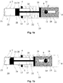
- Figures 1a to 1c shows the operational scheme of three positions of a first embodiment of a door closer 10 according to the invention.
- FIG. 1a shows a first position of this first embodiment of a door closer 10 according to the invention.
- This door closer 10 comprises
- the piston assembly comprises two pistons 15, 16 which move as a single element due to the rod 17 which connects them.
- the first piston 15 is arranged in the first housing 11 to receive the linear movement of the transmission element 13, while the second piston 16 is arranged in the second housing 12.
- the rod 17 goes through both housings to provide a solid connection between the pistons 15, 16.
- the second housing 12 has a stroke zone 20 with a cross section suitable for the second piston 16 to slide tightly.
- the second piston usually has a round section, so the second housing usually has a round section too, which is slightly greater than the round section of the second piston, so that the second piston 16 may slide tightly inside the second housing.
- the way of achieving this tight slide is known by the skilled person.
- the stroke zone 20 has a first end 21 located furthest from the first piston 15 and a second end 22 located closest to the first piston 15, thus dividing the stroke zone 20 in a first half 23, which is the half of the stroke containing the first end 21, and a second half 24, which is the half of the stroke containing the second end 22.
- the second housing 12 comprises several valves:
- the first valve 1, the third valve 3 and the fifth valve 5 are configured to allow only fluid outlet from the stroke zone 20 to the exterior of the second piston 16.
- the third valve 3 is adjustable, so that the door closer manufacturer may choose the rate of fluid outlet allowed by the third valve 3.
- the second valve 2 and the fourth valve 4 are configured to allow only fluid inlet inside the stroke zone 20 from the exterior of the second piston 16.
- the first housing comprises a second hole 8 configured to allow fluid communication between the interior of the first housing 11 and the exterior of the first housing 11.
- the door bar 14 moves the pinion 9, since both elements are solidly attached, and then the gear 19, which is meshed with the pinion 9, converts the rotary movement of the door bar 14 into a translation movement of the first piston 15.
- This first piston 15 compresses the spring 18 and also moves the second piston 16, since both pistons are solidly attached.
- the second piston 16 moves along the stroke zone 20 of the second housing 12.
- the fourth valve 4 lets air enter the second housing 12 while the fifth valve 5 is closed due to pressure gradient.
- the first valve 1 and the third valve 3 let air exit the second housing 12, while the second valve 2 is closed due to pressure gradient. This movement corresponds to the door opening until the second piston 16 reaches the first valve 1.
- Figure 1b shows this door closer 10 when the second piston 16 reaches the first valve 1.
- the portion of the stroke zone which separates the second piston 16 from the first end 21 is called backcheck camera.
- this backcheck will be more or less direct, allowing the door approaching the final angle in a dumped way or directly preventing from moving any further.
- the position of the first valve 1 will define at which angle does this backcheck appear and the adjustment of the third valve 3 will define the way this backcheck is managed.
- the closing stage may begin.
- the spring 18 exerts a return force against the first piston 15, which is transmitted to the second piston 16 by means of the rod 17. This causes the second piston to travel along the stroke zone 20. While this movement takes place, the second valve 2 lets air enter the second housing 12 while the first and third valves 1, 3 are closed due to pressure gradient.
- the fifth valve 5 let air exit the second housing 12, while the fourth valve 4 is closed due to pressure gradient.
- This fifth valve 5 may be adjustable to define the speed of the door closing movement.
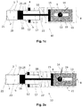
- Figures 2a to 2c shows the operational scheme of three positions of a second embodiment of a door closer 10 according to the invention.
- FIG. 2a shows a first position of this second embodiment of a door closer 10 according to the invention.
- This door closer 10 also comprises
- the second housing 12 comprises some valves which are different from the ones in the previous embodiment.
- the complete set of valves of this embodiment is as follows:
- the first valve 1 and the third valve 3 are configured to allow only fluid outlet from the stroke zone 20 to the exterior of the second piston 16.
- the third valve 3 is adjustable, so that the door closer manufacturer may choose the rate of fluid outlet allowed by the third valve 3.
- the second valve 2 and the sixth valve 6 are configured to allow only fluid inlet inside the stroke zone 20 from the exterior of the second piston 16.
- first hole 7 is configured to allow fluid communication between the interior of the second housing 12 and the exterior of the second housing 12.
- the first housing also comprises a second hole 8 configured to allow fluid communication between the interior of the first housing 11 and the exterior of the first housing 11.
- the door bar 14 moves the pinion 9, since both elements are solidly attached, and then the gear 19, which is meshed with the pinion 9, converts the rotary movement of the door bar 14 into a translation movement of the first piston 15.
- This first piston 15 compresses the spring 18 and also moves the second piston 16, since both pistons are solidly attached.
- the second piston 16 moves along the stroke zone 20 of the second housing 12.
- the first hole 7 lets air enter the second housing 12 while the sixth valve 6 is closed due to pressure gradient.
- the first valve 1 and the third valve 3 let air exit the second housing 12, while the second valve 2 is closed due to pressure gradient. This movement corresponds to the door opening until the second piston 16 reaches the first valve 1.
- Figure 2b shows this door closer 10 when the second piston 16 reaches the first valve 1.
- the portion of the stroke zone which separates the second piston 16 from the first end 21 is called backcheck camera.
- this backcheck will be more or less direct, allowing the door approaching the final angle in a dumped way or directly preventing from moving any further.
- the position of the first valve 1 will define at which angle does this backcheck appear and the adjustment of the third valve 3 will define the way this backcheck is managed.
- the closing stage may begin.
- the spring 18 exerts a return force against the first piston 15, which is transmitted to the second piston 16 by means of the rod 17. This causes the second piston to travel along the stroke zone 20. While this movement takes place, the second valve 2 lets air enter the second housing 12 while the first and third valves 1, 3 are closed due to pressure gradient.
- the first hole 7 let air exit the second housing 12, while the sixth valve 6 is closed due to pressure gradient until it is reached by the second piston 16.
- This second valve 2 may be adjustable to define the speed of the door closing movement.
- this embodiment allows a latch-force final movement.
- the sixth valve 6 also allows air to enter the second housing 12, together with second valve 2. This increasing in the air inlet causes an increase in the closing force in the final angle, when it is necessary to overcome a final latch to keep the door closed.
- Figure 3 shows a door assembly 100 comprising
- This door closer 10 is concealed in the door 50.
Landscapes
- Closing And Opening Devices For Wings, And Checks For Wings (AREA)
Priority Applications (1)
| Application Number | Priority Date | Filing Date | Title |
|---|---|---|---|
| EP19163906.1A EP3712366A1 (de) | 2019-03-19 | 2019-03-19 | Türschliesser und türanordnung |
Applications Claiming Priority (1)
| Application Number | Priority Date | Filing Date | Title |
|---|---|---|---|
| EP19163906.1A EP3712366A1 (de) | 2019-03-19 | 2019-03-19 | Türschliesser und türanordnung |
Publications (1)
| Publication Number | Publication Date |
|---|---|
| EP3712366A1 true EP3712366A1 (de) | 2020-09-23 |
Family
ID=65904031
Family Applications (1)
| Application Number | Title | Priority Date | Filing Date |
|---|---|---|---|
| EP19163906.1A Withdrawn EP3712366A1 (de) | 2019-03-19 | 2019-03-19 | Türschliesser und türanordnung |
Country Status (1)
| Country | Link |
|---|---|
| EP (1) | EP3712366A1 (de) |
Citations (4)
| Publication number | Priority date | Publication date | Assignee | Title |
|---|---|---|---|---|
| GB897848A (en) * | 1957-09-05 | 1962-05-30 | Verreries Appliquees | Improvements in or relating to a door closer |
| JPS565768U (de) * | 1979-06-28 | 1981-01-19 | ||
| WO2008124816A1 (en) * | 2007-04-10 | 2008-10-16 | Wabtec Holding Corp. | Cushioning system for pneumatic cylinder of differential engine |
| US20170247922A1 (en) * | 2016-02-25 | 2017-08-31 | Cmech (Guangzhou) Ltd. | Pneumatic door closer |
-
2019
- 2019-03-19 EP EP19163906.1A patent/EP3712366A1/de not_active Withdrawn
Patent Citations (4)
| Publication number | Priority date | Publication date | Assignee | Title |
|---|---|---|---|---|
| GB897848A (en) * | 1957-09-05 | 1962-05-30 | Verreries Appliquees | Improvements in or relating to a door closer |
| JPS565768U (de) * | 1979-06-28 | 1981-01-19 | ||
| WO2008124816A1 (en) * | 2007-04-10 | 2008-10-16 | Wabtec Holding Corp. | Cushioning system for pneumatic cylinder of differential engine |
| US20170247922A1 (en) * | 2016-02-25 | 2017-08-31 | Cmech (Guangzhou) Ltd. | Pneumatic door closer |
Similar Documents
| Publication | Publication Date | Title |
|---|---|---|
| EP2746508B1 (de) | Türverschlussscharnier, insbesondere für glastüren | |
| EP0469697B1 (de) | Hydraulischer Türschliesser | |
| EP0544253B1 (de) | Dämpfen und Verfahren zur Betätigung einer Tür | |
| CN107109878A (zh) | 用于门、百叶窗或等同物的铰链 | |
| MX2012001550A (es) | Bisagra para camara frigorificas, puertas giratorias o lo similar. | |
| SK284502B6 (sk) | Zatvárač dverí | |
| US5272787A (en) | Overhead concealed door closer, mechanically, hydraulically operated | |
| WO2018142342A1 (en) | System for automatically closing / opening a sliding door or shutter | |
| CN210530582U (zh) | 用于铰链或门关闭器的阻尼机构 | |
| EP1895086A2 (de) | Türschliesser | |
| CN101566028A (zh) | 具有液压延迟关闭的闭门器 | |
| CN1707056B (zh) | 门关闭器 | |
| EP3712366A1 (de) | Türschliesser und türanordnung | |
| DE102010008167A1 (de) | Schieberventil eines Türbetätigers | |
| KR102094189B1 (ko) | 도어 클로저 | |
| EP3371406B1 (de) | Scharnier zur drehbewegung einer tür, eines verschlusses oder dergleichen | |
| CN106103874B (zh) | 活塞‑缸单元和门铰链 | |
| JP3894843B2 (ja) | フロアヒンジ | |
| RU196446U1 (ru) | Гидравлический доводчик двери | |
| US2192745A (en) | Door closer | |
| EP4334558B1 (de) | System zur gesteuerten drehbewegung einer tür, eines flügels oder dergleichen | |
| AU2018215714B2 (en) | Linear actuator, as well as closing / opening system that includes such actuator | |
| JP7109342B2 (ja) | フロアヒンジ | |
| CN215595307U (zh) | 一种液压合页 | |
| KR101092813B1 (ko) | 문닫힘속도 조정 장치 및 도어 클로저 |
Legal Events
| Date | Code | Title | Description |
|---|---|---|---|
| PUAI | Public reference made under article 153(3) epc to a published international application that has entered the european phase |
Free format text: ORIGINAL CODE: 0009012 |
|
| STAA | Information on the status of an ep patent application or granted ep patent |
Free format text: STATUS: THE APPLICATION HAS BEEN PUBLISHED |
|
| AK | Designated contracting states |
Kind code of ref document: A1 Designated state(s): AL AT BE BG CH CY CZ DE DK EE ES FI FR GB GR HR HU IE IS IT LI LT LU LV MC MK MT NL NO PL PT RO RS SE SI SK SM TR |
|
| AX | Request for extension of the european patent |
Extension state: BA ME |
|
| STAA | Information on the status of an ep patent application or granted ep patent |
Free format text: STATUS: REQUEST FOR EXAMINATION WAS MADE |
|
| STAA | Information on the status of an ep patent application or granted ep patent |
Free format text: STATUS: EXAMINATION IS IN PROGRESS |
|
| 17P | Request for examination filed |
Effective date: 20210211 |
|
| RBV | Designated contracting states (corrected) |
Designated state(s): AL AT BE BG CH CY CZ DE DK EE ES FI FR GB GR HR HU IE IS IT LI LT LU LV MC MK MT NL NO PL PT RO RS SE SI SK SM TR |
|
| 17Q | First examination report despatched |
Effective date: 20210315 |
|
| STAA | Information on the status of an ep patent application or granted ep patent |
Free format text: STATUS: THE APPLICATION IS DEEMED TO BE WITHDRAWN |
|
| 18D | Application deemed to be withdrawn |
Effective date: 20211012 |