EP3712239B1 - Emptying of residues - Google Patents
Emptying of residues Download PDFInfo
- Publication number
- EP3712239B1 EP3712239B1 EP19164503.5A EP19164503A EP3712239B1 EP 3712239 B1 EP3712239 B1 EP 3712239B1 EP 19164503 A EP19164503 A EP 19164503A EP 3712239 B1 EP3712239 B1 EP 3712239B1
- Authority
- EP
- European Patent Office
- Prior art keywords
- germination box
- turning
- turning screws
- grain
- box according
- Prior art date
- Legal status (The legal status is an assumption and is not a legal conclusion. Google has not performed a legal analysis and makes no representation as to the accuracy of the status listed.)
- Active
Links
- 230000035784 germination Effects 0.000 claims description 77
- GXCLVBGFBYZDAG-UHFFFAOYSA-N N-[2-(1H-indol-3-yl)ethyl]-N-methylprop-2-en-1-amine Chemical group CN(CCC1=CNC2=C1C=CC=C2)CC=C GXCLVBGFBYZDAG-UHFFFAOYSA-N 0.000 claims description 36
- 239000007921 spray Substances 0.000 claims description 29
- 238000000034 method Methods 0.000 claims description 21
- XLYOFNOQVPJJNP-UHFFFAOYSA-N water Substances O XLYOFNOQVPJJNP-UHFFFAOYSA-N 0.000 claims description 9
- 238000004140 cleaning Methods 0.000 claims description 6
- 238000005507 spraying Methods 0.000 claims description 6
- 239000002184 metal Substances 0.000 claims description 5
- 238000009420 retrofitting Methods 0.000 claims description 5
- 235000013339 cereals Nutrition 0.000 description 46
- 230000003068 static effect Effects 0.000 description 3
- 238000004890 malting Methods 0.000 description 2
- 238000004519 manufacturing process Methods 0.000 description 2
- 230000001360 synchronised effect Effects 0.000 description 2
- 240000005979 Hordeum vulgare Species 0.000 description 1
- 235000007340 Hordeum vulgare Nutrition 0.000 description 1
- 244000007853 Sarothamnus scoparius Species 0.000 description 1
- 244000052616 bacterial pathogen Species 0.000 description 1
- 239000007795 chemical reaction product Substances 0.000 description 1
- 239000012459 cleaning agent Substances 0.000 description 1
- 238000011109 contamination Methods 0.000 description 1
- 230000001419 dependent effect Effects 0.000 description 1
- 239000000463 material Substances 0.000 description 1
- 238000012986 modification Methods 0.000 description 1
- 230000004048 modification Effects 0.000 description 1
- 239000000047 product Substances 0.000 description 1
- 239000007787 solid Substances 0.000 description 1
Images


Classifications
-
- C—CHEMISTRY; METALLURGY
- C12—BIOCHEMISTRY; BEER; SPIRITS; WINE; VINEGAR; MICROBIOLOGY; ENZYMOLOGY; MUTATION OR GENETIC ENGINEERING
- C12C—BEER; PREPARATION OF BEER BY FERMENTATION; PREPARATION OF MALT FOR MAKING BEER; PREPARATION OF HOPS FOR MAKING BEER
- C12C1/00—Preparation of malt
- C12C1/15—Grain or malt turning, charging or discharging apparatus
-
- C—CHEMISTRY; METALLURGY
- C12—BIOCHEMISTRY; BEER; SPIRITS; WINE; VINEGAR; MICROBIOLOGY; ENZYMOLOGY; MUTATION OR GENETIC ENGINEERING
- C12C—BEER; PREPARATION OF BEER BY FERMENTATION; PREPARATION OF MALT FOR MAKING BEER; PREPARATION OF HOPS FOR MAKING BEER
- C12C1/00—Preparation of malt
- C12C1/027—Germinating
- C12C1/033—Germinating in boxes or drums
-
- C—CHEMISTRY; METALLURGY
- C12—BIOCHEMISTRY; BEER; SPIRITS; WINE; VINEGAR; MICROBIOLOGY; ENZYMOLOGY; MUTATION OR GENETIC ENGINEERING
- C12C—BEER; PREPARATION OF BEER BY FERMENTATION; PREPARATION OF MALT FOR MAKING BEER; PREPARATION OF HOPS FOR MAKING BEER
- C12C1/00—Preparation of malt
- C12C1/027—Germinating
- C12C1/0275—Germinating on single or multi-stage floors
Definitions
- the present invention relates to a germination box, in particular a device and a method for emptying a germination box.
- Germination boxes are used in malthouses to germinate grain.
- the grain is stored in the germination box under controlled temperature and humidity conditions. This is typically rectangular or round and, in the case of a round germination box, can have a diameter of 15 - 40 m.
- Such germination boxes are, for example EP 2 258 822 , EP 2 258 825 , DE 1442114 and EP 1 641 909 known.
- the grain In order to ensure uniform germination, the grain must be turned.
- a beam is usually provided to which vertically arranged turning screws are attached. The turning screws are operated in pairs in opposite directions.
- tools can be attached to the end edge of the turning auger facing the ground, which do not extend over the entire end edge of the turning auger and are used to loosen the grain during the turning process. Without this loosening and the associated lifting of the grain residues or green malt residues from the bottom of the germination box, the grain or green malt would stick to the floor and solidify.
- the bar is movably arranged within the germination box in order to be able to turn all the grain. This is, for example, with a device like this DE 10 2004 032 442 well known supported and fastened. If a rotating tray is provided, the beam is fixed and the base of the tray is rotatable.
- a horizontal conveyor device is usually also provided, which is attached to the beam and can be moved in the vertical direction. This is used to transport the grain or green malt towards an unloading station after the germination process.
- the unloading station can be an opening or a discharge shaft.
- the unloading station can be arranged in the center or on an outer wall within the germination box.
- the turning screws should not reach directly to the ground, otherwise the metal of the turning screws would rub on the metal of the ground.
- a gap of 2 to 3cm is preferred because due to the size of the germination box, manufacturing tolerances and thermal expansion can lead to unevenness in the floor.
- the turning augers must maintain a specified distance from the ground.
- several 100 kg can remain in the germination box.
- the invention comprises a germination box with a container for holding grain or green malt, the container having a bottom.
- a bar is arranged inside the container.
- a conveyor device in particular a screw, arranged horizontally to the floor for loading and unloading the container, the conveyor device being movable in the vertical direction and essentially parallel to the floor.
- stripping tools are attached at the lower end, i.e. at an end facing the bottom of each of the turning screws.
- the turning screws are also set up to be operated in the same direction to empty the germination box.
- the distance between the stripping tools and the floor is preferably between 0 and 2 mm and is particularly preferably 0.5 mm.
- the stripping tools can protrude radially beyond the edge of the respective turning screw. Furthermore, they can Stripping tools can be curved or slanted.
- the bottom preferably has a sieve plate.
- the germination box can be designed as a fixed tray or as a rotating tray.
- the stripping tools can be arranged in such a way that circumferential circles of the stripping tools of adjacent turning screws touch each other.
- the stripping tools can also be made of plastic or metal.
- the grain or green malt residues on the ground can be transported towards an unloading station when the turning screws rotate in the same direction.
- the germination box also preferably has a high-pressure spray bar which is attached to a housing of the conveyor and which is set up to remove grain or green malt residues from the turning screws by spraying onto the turning screws.
- the high-pressure spray bar can preferably be fed with water.
- the invention further provides a method for emptying a germination box and a method for retrofitting a germination box, in particular a germination box according to the preamble of claim 1.
- the bar 4 is moved linearly within the germination box, in the case of round germination boxes in the radial direction around the center of the germination box. This is called a solid horde.
- the base 7 can be movable and the beam 4 can be static. This is also known as a rotating horde.
- the conveyor 1 is used to load and unload the germination box with grain or green malt and is preferably designed as a screw. Furthermore, a spray bar for moistening the grain in the germination box can be attached to the conveyor 1 (not shown). A spray bar for cleaning the floor 7 can also be attached.
- the turning screws 3 are operated in pairs in opposite directions and either the base 7 or the beam 4 is moved within the germination box in order to completely turn the grain or green malt during germination. Turning ensures even germination and prevents the germs from growing together, making transport more difficult.
- the germination process usually takes 3-5 days, with the grain or green malt being turned mechanically at least once a day.
- the grain or green malt is conveyed by means of the conveyor 1 towards one end of the beam 4 and discharged there via an unloading station 9, for example a discharge chute.
- the unloading station 9 is usually located in the center, in the case of a rectangular germination box, usually along one of the sides of the germination box.
- the amount of these grain residues or green malt residues can be up to several 100 kg, depending on the size of the germination box and the batch in it. Based on annual production, 300-400 t of end product loss can occur.
- stripping tools 6 are provided at the lower end of each of the turning screws.
- the distance between the base 7 and the stripping tools 6 is preferably between 0 and 2 mm, particularly preferably 0.5 mm.
- essentially no gap is formed between the stripping tools 6 of adjacent turning screws 3.
- the circumferential circle here is to be understood as the imaginary line which forms the radially outer end of a stripping tool 6 during the rotation of the turning screw 3.
- essentially no gap is formed between the surfaces on the bottom that are swept over by the stripping tools of two adjacent turning screws.
- the stripping tools 6 can be made of plastic, metal or another suitable material. The stripping tools 6 can be retrofitted to existing systems without much effort.
- the surfaces of the spiral of the turning screws 3 are first cleaned using a water jet from a high-pressure spray bar 5, the product remaining on it falls to the bottom of the germination box.
- the turning screws 3 can rotate in the same direction or in opposite directions.
- the turning screws 3, which in normal operation are operated in pairs in opposite directions to turn the grain or green malt during malting, are operated in the same direction (see direction of rotation arrows in Figure 2 ), whereby the speed preferably remains essentially unchanged.
- grain residues or green malt residues remaining on the floor 7 are moved from one turning screw 3 to the adjacent turning screw 3 and in by means of the stripping tools 6 Transported towards one end of the beam 4, at which the unloading station 9 is located.
- FIG 3 shows a detailed view of the conveyor device 1 according to the invention.
- a high-pressure spray bar 5 is attached to it.
- At least one nozzle is directed at one of the turning screws 3.
- Several nozzles can also be provided per turning screw.
- the existing water supply which is set up to moisten the grain during malting and to clean the floor 7 using high pressure, can be used by connecting the additional high-pressure spray bar 5 to it.
- the conveyor device 1 is movable in the vertical direction. By moving the conveyor device 1 up and down while simultaneously rotating the turning screws 3 and operating the high-pressure spray bar 5, the turning screws 3 can be freed of grain residues or green malt residues over their entire height.
- the high-pressure spray bar 5 is preferably operated with little water and a lot of pressure.
- the fallen grain residues or green malt residues are then transported towards the unloading station 9 by means of the stripping tools 6 described above and can be further processed.
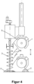
- FIG 4 is a side view of the device according to the invention, on which the cleaning of the turning screws 3 by moving up and down the conveyor device 1 or the high-pressure spray bar 5 attached to it is shown.
- the conveyor device 1 is shown once in a maximum vertical position and once in a vertically lowered position.
- the water jet 8 of the high-pressure spray bar 5 is shown with solid lines.
- the turning screws 3 are freed from grain residues or green malt residues by the high-pressure spray bar 5, which then fall onto the floor 7. Grain or green malt remaining in the conveyor device 1 can also fall down and collect on the floor 7 as grain residues or green malt residues 2.
- the grain residues or green malt residues 2 are then, like described above, transported towards one end of the beam 4 to the unloading station 9 by means of the turning screws 3 operated in the same direction and the stripping tools 6 (not shown) attached thereto.
- Figure 5 shows a schematic view of the turning screws 3 according to the invention as a top view of the germination box.
- the stripping tools are attached to the underside of the last flank profile of the respective turning screw 3, ie on the side of the respective turning screw 3 facing the bottom 7.
- the stripping tools 6 can rest on the worm shaft 10 of the turning screws 3.
- the stripping tools 6 can be designed to be curved.
- the stripping tools 6 can be concave in relation to the direction of rotation.
- the stripping tools 6 may be attached obliquely with respect to a radial direction on the turning screw 3.
- the stripping tools 6 can protrude over the circumference of the turning screws 3.
- the invention further includes a method for emptying a germination box as described above.
- the method according to the invention includes emptying the germination box by conveying the grain or green malt to an unloading station 9 by means of the horizontally arranged conveyor device and the simultaneous operation of the turning screws in such a way that grain or green malt residues located on the bottom of the container after emptying are removed in the direction by means of the stripping tools the unloading station 9 is transported.
- the conveyor device 1 and thus also the high-pressure spray bar 5 are preferably moved in the vertical direction during spraying.
- the movement includes in particular a movement over the entire height of the turning screws 3 in order to be able to completely free them of grain residues or green malt residues.
- the invention also includes a method for retrofitting a germination box, in particular a germination box with a container for holding grain, the container having a base and a beam which is arranged within the container.
- the germination box to be retrofitted can preferably also have a conveyor device arranged horizontally to the floor, in particular a screw, for loading and unloading the container, wherein the conveyor device can be movable in the vertical direction and attached to the beam. Turning screws arranged vertically to the ground are attached to the beam.
- stripping tools are attached to the lower end of each of the turning screws according to the retrofitting method according to the invention and the turning screws are set up in such a way that they can be operated in the same direction.
- the method preferably further includes attaching a movable high-pressure spray bar 5 for cleaning the turning screws 3, the high-pressure spray bar 5 having a plurality of nozzles and at least one nozzle of the high-pressure spray bar 5 being directed towards a turning screw 3.
- the high-pressure spray bar 5 can be moved vertically. If a conveyor 1 as described above is present, the high-pressure spray bar 5 can be attached to the conveyor 1.
- the measures described ie the stripping tools 6 in conjunction with the synchronous operation of the turning screws 3 and the high-pressure spray bar 5, can be retrofitted independently of one another in existing systems. This only requires minor structural changes, such as a reversing contactor, or software adjustments.
- the high-pressure spray bar 5 which uses the existing high-pressure system, grain residues or green malt residues can be removed from the turning screws 3 can be removed.
- By changing the direction of rotation of every second turning screw 3 in conjunction with the stripping tools 6 attached to each turning screw 3, remaining grain residues or green malt residues 2 can be transported from the floor 7 towards one end of the beam 4 to the unloading station 9.
- the grain can thus be transported vertically by the turning screws 3 in opposite-rotating pairs and horizontally in co-rotating operation. This enables a much more economical operation of the system and a significant reduction in the amount of grain remaining after the germination box has been emptied by the conveyor 1. Furthermore, it is no longer necessary for people to be in the danger area under the conveyor 1 to clean or empty the germination box stop.
- the invention also includes individual features in the figures, even if they are shown there in connection with other features and/or are not mentioned above. Furthermore, the term “comprise” and derivatives thereof do not exclude other elements or steps. Likewise, the indefinite article “a” or “an” and derivatives thereof does not exclude a multitude. The functions of several features listed in the claims can be fulfilled by a unit. The terms “substantially”, “approximately”, “approximately” and the like in connection with a property or a value also define in particular exactly the property or exactly the value. All reference symbols in the claims are not to be understood as limiting the scope of the claims.
Landscapes
- Chemical & Material Sciences (AREA)
- Organic Chemistry (AREA)
- Engineering & Computer Science (AREA)
- General Health & Medical Sciences (AREA)
- Life Sciences & Earth Sciences (AREA)
- Biochemistry (AREA)
- Bioinformatics & Cheminformatics (AREA)
- General Engineering & Computer Science (AREA)
- Health & Medical Sciences (AREA)
- Genetics & Genomics (AREA)
- Food Science & Technology (AREA)
- Wood Science & Technology (AREA)
- Zoology (AREA)
- Apparatus Associated With Microorganisms And Enzymes (AREA)
- Filling Or Emptying Of Bunkers, Hoppers, And Tanks (AREA)
- Pretreatment Of Seeds And Plants (AREA)
Description
Die vorliegende Erfindung betrifft einen Keimkasten, insbesondere eine Vorrichtung und ein Verfahren zum Entleeren eines Keimkastens.The present invention relates to a germination box, in particular a device and a method for emptying a germination box.
Keimkästen werden in Mälzereien zum Keimen von Getreide eingesetzt. Hierfür wird das Getreide unter geregelten Temperatur- und Feuchtigkeitsbedingungen im Keimkasten gelagert. Dieser ist typischerweise rechteckig oder rund und kann im Falle eines runden Keimkastens einen Durchmesser von 15 - 40 m aufweisen. Derartige Keimkästen sind beispielsweise aus
Der Balken ist im Falle einer festen Horde innerhalb des Keimkastens beweglich angeordnet, um das gesamte Getreide wenden zu können. Dieser ist beispielsweise mit einer Vorrichtung wie aus
Zum Be- und Entladen des Keimkastens ist in der Regel ferner eine horizontale Förderereinrichtung vorgesehen, die am Balken befestigt ist und in vertikaler Richtung verfahrbar ist. Hiermit wird das Getreide oder Grünmalz nach dem Keimprozess in Richtung einer Entladestation transportiert. Die Entladestation kann eine Öffnung oder ein Abführschacht sein. Die Entladestation kann im Zentrum oder an einer Außenwand innerhalb des Keimkastens angeordnet sein.For loading and unloading the germination box, a horizontal conveyor device is usually also provided, which is attached to the beam and can be moved in the vertical direction. This is used to transport the grain or green malt towards an unloading station after the germination process. The unloading station can be an opening or a discharge shaft. The unloading station can be arranged in the center or on an outer wall within the germination box.
Die Wendeschnecken sollten nicht direkt bis auf den Boden reichen, weil ansonsten das Metall der Wendeschnecken auf dem Metall des Bodens reiben würde. Hier ist ein Spalt von 2 bis 3cm bevorzugt, da aufgrund der Größe des Keimkastens Fertigungstoleranzen und Wärmeausdehnung zu Unebenheiten des Bodens führen können. Damit sich die Wendeschnecken nicht mit dem Boden verhaken oder diesen beschädigen, müssen die Wendeschnecken einen vorgegebenen Abstand zum Boden einhalten. Beim Entladen des Keimkastens ist es jedoch unvermeidlich, dass Getreide oder Grünmalzreste auf den Wende- bzw. Förderschnecken oder auf dem Boden des Keimkastens verbleibt. Je nach Größe des Keimkastens können so mehrere 100 kg im Keimkasten verbleiben. In herkömmlichen Mälzereien wird daher das verbliebene Getreide oder Grünmalzreste im Keimkasten belassen, wodurch es zu einer Kontamination der neuen Charge kommt oder der Keimkasten wird manuell gereinigt. Dies erfordert einen hohen Aufwand an Zeit und Personal sowie hohe Sicherheitsvorkehrungen für die Arbeiten an der Maschine und in dem dazugehörigen Prozessraum.The turning screws should not reach directly to the ground, otherwise the metal of the turning screws would rub on the metal of the ground. Here is a gap of 2 to 3cm is preferred because due to the size of the germination box, manufacturing tolerances and thermal expansion can lead to unevenness in the floor. To ensure that the turning augers do not get caught on the ground or damage it, the turning augers must maintain a specified distance from the ground. However, when unloading the germination box, it is inevitable that grain or green malt remains remain on the turning or conveyor screws or on the bottom of the germination box. Depending on the size of the germination box, several 100 kg can remain in the germination box. In conventional malthouses, the remaining grain or green malt residues are left in the germination box, which leads to contamination of the new batch, or the germination box is cleaned manually. This requires a lot of time and personnel as well as high safety precautions for work on the machine and in the associated process room.
Daher ist eine Aufgabe der vorliegenden Erfindung eine Vorrichtung und ein Verfahren bereitzustellen, die es ermöglichen, eine Restentleerung des Keimkastens durchzuführen.It is therefore an object of the present invention to provide a device and a method which make it possible to empty the germination box.
Die Erfindung ist durch die Merkmale der unabhängigen Ansprüche 1, 11 und 14 definiert; die abhängigen Ansprüche definieren Ausführungsformen der Erfindung.The invention is defined by the features of
Die Erfindung umfasst einen Keimkasten mit einem Behälter zum Aufnehmen von Getreide oder Grünmalz, wobei der Behälter einen Boden aufweist. Innerhalb des Behälters ist ein Balken angeordnet. Am Balken angeordnet ist eine horizontal zum Boden angeordnete Fördereinrichtung, insbesondere eine Schnecke, zum Be- und Entladen des Behälters, wobei die Fördereinrichtung in vertikaler Richtung und im Wesentlichen parallel zum Boden verfahrbar ist. Ferner sind am Balken mehrere vertikal zum Boden angeordnete Wendeschnecken angebracht, die zum Wenden des Getreides oder Grünmalzes paarweise gegenläufig betrieben werden. Am unteren Ende, d.h. an einem dem Boden zugewandten Ende jeder der Wendeschnecken sind Abstreifwerkzeuge angebracht. Die Wendeschnecken sind ferner eingerichtet, zum Entleeren des Keimkastens gleichläufig betrieben zu werden.The invention comprises a germination box with a container for holding grain or green malt, the container having a bottom. A bar is arranged inside the container. Arranged on the beam is a conveyor device, in particular a screw, arranged horizontally to the floor for loading and unloading the container, the conveyor device being movable in the vertical direction and essentially parallel to the floor. Furthermore, there are several turning screws arranged vertically to the ground on the beam, which are operated in pairs in opposite directions to turn the grain or green malt. At the lower end, i.e. at an end facing the bottom of each of the turning screws, stripping tools are attached. The turning screws are also set up to be operated in the same direction to empty the germination box.
Der Abstand zwischen den Abstreifwerkzeugen und dem Boden liegt bevorzugt zwischen 0 und 2 mm und beträgt besonders bevorzugt 0,5 mm. Die Abstreifwerkzeuge können radial über den Rand der jeweiligen Wendeschnecke überstehen. Ferner können die Abstreifwerkzeuge gebogen oder schräg ausgeführt sein. Der Boden weist bevorzugt ein Siebblech auf.The distance between the stripping tools and the floor is preferably between 0 and 2 mm and is particularly preferably 0.5 mm. The stripping tools can protrude radially beyond the edge of the respective turning screw. Furthermore, they can Stripping tools can be curved or slanted. The bottom preferably has a sieve plate.
Der Keimkasten kann als feste Horde oder als Drehhorde ausgebildet sein. Die Abstreifwerkzeuge können derart angeordnet sein, dass sich Umfangskreise der Abstreifwerkzeuge benachbarter Wendeschnecken berühren. Die Abstreifwerkzeuge können ferner aus Kunststoff oder Metall gebildet sein.The germination box can be designed as a fixed tray or as a rotating tray. The stripping tools can be arranged in such a way that circumferential circles of the stripping tools of adjacent turning screws touch each other. The stripping tools can also be made of plastic or metal.
Mittels der Abstreifwerkzeuge kann bei gleichläufiger Drehung der Wendeschnecken das auf dem Boden befindliche Getreide oder Grünmalzreste in Richtung einer Entladestation befördert werden.Using the stripping tools, the grain or green malt residues on the ground can be transported towards an unloading station when the turning screws rotate in the same direction.
Der Keimkasten weist ferner bevorzugt eine Hochdrucksprühleiste auf, die an einem Gehäuse der Fördereinrichtung angebracht ist und die eingerichtet ist, um durch Sprühen auf die Wendeschnecken Getreide oder Grünmalzreste von den Wendeschnecken zu entfernen. Die Hochdrucksprühleiste ist bevorzugt mit Wasser speisbar.The germination box also preferably has a high-pressure spray bar which is attached to a housing of the conveyor and which is set up to remove grain or green malt residues from the turning screws by spraying onto the turning screws. The high-pressure spray bar can preferably be fed with water.
Durch die Erfindung werden ferner ein Verfahren zum Entleeren eines Keimkastens sowie ein Verfahren zum Nachrüsten eines Keimkastens, insbesondere eines Keimkastens gemäß dem Oberbegriff des Anspruchs 1, bereitgestellt.The invention further provides a method for emptying a germination box and a method for retrofitting a germination box, in particular a germination box according to the preamble of
Die Erfindung wird anhand der Figuren weiter beschrieben. Es zeigen
-
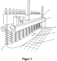
Fig. 1 eine perspektivische Gesamtansicht der erfindungsgemäßen Vorrichtung -
Fig. 2 eine Detailansicht der erfindungsgemäßen Wendeschnecken im Bereich A vonFig. 1 -
Fig. 3 eine Detailansicht der erfindungsgemäßen Fördereinrichtung -
Fig. 4 eine Seitenansicht der erfindungsgemäßen Vorrichtung -
Fig. 5 eine schematische Ansicht der erfindungsgemäßen Wendeschnecken -
Fig. 6 eine weitere schematische Ansicht der erfindungsgemäßen Wendeschnecken.
-
Fig. 1 a perspective overall view of the device according to the invention -
Fig. 2 a detailed view of the turning screws according to the invention in area A ofFig. 1 -
Fig. 3 a detailed view of the conveyor device according to the invention -
Fig. 4 a side view of the device according to the invention -
Fig. 5 a schematic view of the turning screws according to the invention -
Fig. 6 another schematic view of the turning screws according to the invention.
Die Fördereinrichtung 1 dient zum Be- und Entladen des Keimkastens mit Getreide oder Grünmalz und ist bevorzugt als Schnecke ausgeführt. Ferner kann an der Fördereinrichtung 1 eine Sprühleiste zum Befeuchten des Getreides im Keimkasten angebracht sein (nicht gezeigt). Ebenfalls kann eine Sprühleiste zum Reinigen des Bodens 7 angebracht sein. Die Wendeschnecken 3 werden paarweise gegenläufig betrieben und entweder der Boden 7 oder der Balken 4 innerhalb des Keimkastens bewegt, um das Getreide oder Grünmalz während des Keimens vollständig zu wenden. Durch das Wenden wird ein gleichmäßiges Keimen sichergestellt sowie verhindert, dass die Keime miteinander verwachsen und so ein Transport erschwert wird.The
Der Keimvorgang dauert gewöhnlich 3-5 Tage, wobei mindestens einmal täglich das Getreide oder Grünmalz mechanisch gewendet wird. Nach Abschluss des Keimvorgangs wird das Getreide oder Grünmalz mittels der Fördereinrichtung 1 in Richtung eines Endes des Balkens 4 befördert und dort über eine Entladestation 9, beispielsweise einen Abwurfschacht abgeführt. Im Fall eines runden Keimkastens befindet sich die Entladestation 9 gewöhnlich im Zentrum, im Falle eines rechteckigen Keimkastens gewöhnlich entlang einer der Seiten des Keimkastens. Beim Entleeren verbleiben jedoch unvermeidlich Getreidereste oder Grünmalzreste 2 auf dem Boden 7, den Wendeschnecken 3 oder der Fördereinrichtung 1 bzw. fallen von der Fördereinrichtung 1 auf den Boden 7 herab. In der Regel ist eine vollständige Entleerung mittels der Schneckenförderung der Fördereinrichtung 1 nicht gewährleistet. Die Menge dieser Getreidereste oder Grünmalzreste kann je nach Größe des Keimkastens und der darin befindlichen Charge bis zu mehreren 100 kg betragen. Gerechnet auf die Jahresproduktion können so 300-400 t Endproduktverlust auftreten.The germination process usually takes 3-5 days, with the grain or green malt being turned mechanically at least once a day. After the germination process has been completed, the grain or green malt is conveyed by means of the
In herkömmlichen Anlagen werden diese Getreidereste oder Grünmalzreste entweder im Keimkasten belassen und kontaminieren so die neue Charge oder sie müssen manuell mittels Besen oder ähnlichem von den Wendeschnecken 3, der Fördereinrichtung 1 und dem Boden 7 entfernt werden. Die manuelle Reinigung erfordert jedoch hohe Sicherheitsstandards, da das Arbeiten im Keimkasten unter der Fördereinrichtung 1 gefährlich ist und somit Maßnahmen zur Sicherung der Fördereinrichtung 1 notwendig sind. Insbesondere besteht aufgrund des glatten Bodens, der evtl. verwendeten Reinigungsmittel sowie beweglicher Teile der Anlage Gefahr für das Reinigungspersonal.In conventional systems, these grain residues or green malt residues are either left in the germination box and thus contaminate the new batch or they have to be removed manually from the turning screws 3, the
Daher sind an der erfindungsgemäßen Vorrichtung Mittel vorgesehen, um die Anlage automatisiert restentleeren zu können. Mit Bezug auf
Zum Entleeren des Bodens 7 werden zunächst die Flächen der Wendel der Wendeschnecken 3 mittels Wasserstrahl aus einer Hochdrucksprühleiste 5 abgereinigt, das darauf liegengebliebene Produkt fällt auf den Boden des Keimkastens. Die Wendeschnecken 3 können gleichläufig oder gegenläufig drehen. Dann werden die Wendeschnecken 3, die im gewöhnlichen Betrieb zum Wenden des Getreides oder Grünmalzes während des Mälzens paarweise gegenläufig betrieben werden, gleichläufig betrieben (s. Drehrichtungspfeile in
Die Erfindung umfasst ferner ein Verfahren zum Entleeren eines Keimkastens wie oben beschrieben. Insbesondere umfasst das erfindungsgemäße Verfahren das Entleeren des Keimkastens durch Fördern des Getreides oder Grünmalzes mittels der horizontal angeordneten Fördereinrichtung zu einer Entladestation 9 und das gleichläufige Betreiben der Wendeschnecken derart, dass mittels der Abstreifwerkzeuge auf dem Boden des Behälters nach dem Entleeren befindliches Getreide oder Grünmalzreste in Richtung der Entladestation 9 befördert wird.The invention further includes a method for emptying a germination box as described above. In particular, the method according to the invention includes emptying the germination box by conveying the grain or green malt to an unloading station 9 by means of the horizontally arranged conveyor device and the simultaneous operation of the turning screws in such a way that grain or green malt residues located on the bottom of the container after emptying are removed in the direction by means of the stripping tools the unloading station 9 is transported.
Bevorzugt werden durch Sprühen unter Hochdruck insbesondere von Wasser aus der an der Fördereinrichtung angeordneten Hochdrucksprühleiste auf die Wendeschnecken Getreidereste oder Grünmalzreste von den Wendeschnecken entfernt.Grain residues or green malt residues are preferably removed from the turning screws by spraying under high pressure, in particular water, from the high-pressure spray bar arranged on the conveyor onto the turning screws.
Bevorzugt wird bei dem erfindungsgemäßen Verfahren während des Sprühens die Fördereinrichtung 1 und damit auch die Hochdrucksprühleiste 5 in vertikaler Richtung bewegt. Die Bewegung umfasst insbesondere eine Bewegung über die gesamte Höhe der Wendeschnecken 3, um diese vollständig von Getreideresten oder Grünmalzreste befreien zu können.In the method according to the invention, the
Die Erfindung umfasst ferner auch ein Verfahren zum Nachrüsten eines Keimkastens, insbesondere eines Keimkastens mit einem Behälter zum Aufnehmen von Getreide, wobei der Behälter einen Boden aufweist und einem Balken, der innerhalb des Behälters angeordnet ist. Der nachzurüstende Keimkasten kann bevorzugt auch eine horizontal zum Boden angeordnete Fördereinrichtung, insbesondere eine Schnecke, zum Be- und Entladen des Behälters aufweisen, wobei die Fördereinrichtung in vertikaler Richtung beweglich und am Balken befestigt sein kann. Am Balken sind vertikal zum Boden angeordnete Wendeschnecken angebracht. Um einen solchen bereits bekannten Keimkasten nachzurüsten, werden gemäß dem erfindungsgemäßen Nachrüstungsverfahren Abstreifwerkzeuge am unteren Ende jeder der Wendeschnecken angebracht und die Wendeschnecken derart eingerichtet, dass sie gleichläufig betrieben werden können.The invention also includes a method for retrofitting a germination box, in particular a germination box with a container for holding grain, the container having a base and a beam which is arranged within the container. The germination box to be retrofitted can preferably also have a conveyor device arranged horizontally to the floor, in particular a screw, for loading and unloading the container, wherein the conveyor device can be movable in the vertical direction and attached to the beam. Turning screws arranged vertically to the ground are attached to the beam. In order to retrofit such an already known germination box, stripping tools are attached to the lower end of each of the turning screws according to the retrofitting method according to the invention and the turning screws are set up in such a way that they can be operated in the same direction.
Bevorzugt umfasst das Verfahren ferner das Anbringen einer verfahrbaren Hochdrucksprühleiste 5 zum Reinigen der Wendeschnecken 3, wobei die Hochdrucksprühleiste 5 mehrere Düsen aufweist und wobei je mindestens eine Düse der Hochdrucksprühleiste 5 auf eine Wendeschnecke 3 gerichtet ist. Die Hochdrucksprühleiste 5 kann vertikal verfahrbar sein. Falls eine Fördereinrichtung 1 wie oben beschrieben vorhanden ist, kann die Hochdrucksprühleiste 5 an der Fördereinrichtung 1 angebracht werden.The method preferably further includes attaching a movable high-
Die beschriebenen Maßnahmen, d.h. die Abstreifwerkzeuge 6 in Verbindung mit dem gleichläufigen Betrieb der Wendeschnecken 3 sowie die Hochdrucksprühleiste 5 können unabhängig voneinander in bestehenden Anlagen nachgerüstet werden. Hierfür sind nur geringe bauliche Änderungen, wie beispielsweise eine Wendeschütze, oder eine Softwareanpassung notwendig. Mittels der Hochdrucksprühleiste 5, die das bestehende Hochdrucksystem nutzt, können Getreidereste oder Grünmalzreste von den Wendeschnecken 3 entfernt werden. Durch die Drehrichtungsänderung jeder zweiten Wendeschnecke 3 in Verbindung mit den an jeder Wendeschnecke 3 angebrachten Abstreifwerkzeugen 6 können verbliebene Getreidereste oder Grünmalzreste 2 vom Boden 7 in Richtung eines Endes des Balkens 4 zur Entladestation 9 transportiert werden. Somit kann das Getreide durch die Wendeschnecken 3 im paarweise gegenläufigen Betrieb senkrecht und im gleichläufigen Betrieb waagerecht transportiert werden. Dies ermöglicht einen wesentlich wirtschaftlicheren Betrieb der Anlage sowie eine erhebliche Reduktion der Menge an verbliebenem Getreide nach der Entleerung des Keimkastens durch die Fördereinrichtung 1. Weiterhin ist es nicht mehr notwendig, dass sich Personen im Gefahrenbereich unter der Fördereinrichtung 1 zum Reinigen bzw. Entleeren des Keimkastens aufhalten.The measures described, ie the stripping
Die Erfindung kann sowohl in einer festen Horde, also einer Anlage bei der der Boden statisch, der Balken jedoch beweglich ist, als auch in einer Drehhorde mit statischem Balken und beweglichem Boden, eingesetzt werden.The invention can be used both in a fixed rack, i.e. a system in which the floor is static but the beam is movable, as well as in a rotating rack with a static beam and a movable floor.
Obwohl die Erfindung mittels der Figuren und der zugehörigen Beschreibung dargestellt und detailliert beschrieben ist, sind diese Darstellung und diese detaillierte Beschreibung illustrativ und beispielhaft zu verstehen und nicht als die Erfindung einschränkend. Es versteht sich, dass Fachleute Änderungen und Abwandlungen machen können, ohne den Umfang der folgenden Ansprüche zu verlassen.Although the invention has been illustrated and described in detail by means of the figures and the accompanying description, this illustration and this detailed description are to be understood as illustrative and exemplary and not as limiting the invention. It is understood that those skilled in the art may make changes and modifications without departing from the scope of the following claims.
Die Erfindung umfasst ebenfalls einzelne Merkmale in den Figuren auch wenn sie dort im Zusammenhang mit anderen Merkmalen gezeigt sind und/oder vorstehend nicht genannt sind. Im Weiteren schließt der Ausdruck "umfassen" und Ableitungen davon andere Elemente oder Schritte nicht aus. Ebenfalls schließt der unbestimmte Artikel "ein" bzw. "eine" und Ableitungen davon eine Vielzahl nicht aus. Die Funktionen mehrerer in den Ansprüchen aufgeführter Merkmale können durch eine Einheit erfüllt sein. Die Begriffe "im Wesentlichen", "etwa", "ungefähr" und dergleichen in Verbindung mit einer Eigenschaft beziehungsweise einem Wert definieren insbesondere auch genau die Eigenschaft beziehungsweise genau den Wert. Alle Bezugszeichen in den Ansprüchen sind nicht als den Umfang der Ansprüche einschränkend zu verstehen.The invention also includes individual features in the figures, even if they are shown there in connection with other features and/or are not mentioned above. Furthermore, the term “comprise” and derivatives thereof do not exclude other elements or steps. Likewise, the indefinite article “a” or “an” and derivatives thereof does not exclude a multitude. The functions of several features listed in the claims can be fulfilled by a unit. The terms “substantially”, “approximately”, “approximately” and the like in connection with a property or a value also define in particular exactly the property or exactly the value. All reference symbols in the claims are not to be understood as limiting the scope of the claims.
- 11
- Fördereinrichtungfunding facility
- 22
- Getreide oder GrünmalzGrain or green malt
- 33
- WendeschneckeTurning screw
- 44
- Balkenbar
- 55
- HochdrucksprühleisteHigh pressure spray bar
- 66
- Abstreifwerkzeugstripping tool
- 77
- HordenbodenHorde floor
- 88th
- Wasserstrahlwater jet
- 99
- EntladestationUnloading station
- 1010
- Schneckenwelleworm shaft
Claims (15)
- A germination box comprising:a container for receiving grain, wherein the container has a base (7),a beam (4) arranged inside the container, anda conveying device (1), in particular a screw, arranged horizontally to the base (7) for loading and unloading the container, wherein the conveying device (1) is movable in the vertical direction, and wherein the conveying device (1) is fastened to the beam (4), anda plurality of turning screws (3) arranged on the beam (4) vertically to the base (7), wherein the turning screws (3) are operated in pairs in opposite directions to turn the grain,characterized in thata stripping tool (6) is arranged at an end of each of the turning screws (3) facing the base, andthe turning screws (3) are configured to be operated in the same direction for emptying the germination box.
- The germination box according to claim 1, wherein the distance between the stripping tools (6) and the base (7) is between 0 and 2 mm and preferably 0.5 mm.
- The germination box according to claim 1 or 2, wherein the stripping tools (6) project radially beyond the edge of the respective turning screw (3).
- The germination box according to any one of the preceding claims, wherein the stripping tools (6) are curved.
- The germination box according to any one of the preceding claims, wherein the base (7) comprises a sieve plate.
- The germination box according to any one of the preceding claims, wherein the stripping tools (6) are arranged in such a way that circumferential circles of the stripping tools (6) of adjacent turning screws (3) touch each other.
- The germination box according to any one of the preceding claims, wherein the stripping tools (6) are formed from plastic or metal.
- The germination box according to any one of the preceding claims, wherein the grain located on the base (7) is conveyed in the direction of an unloading station (9) by means of the stripping tools (6) while the turning screws (3) are rotating in the same direction.
- The germination box according to any one of the preceding claims, wherein the germination box further comprises a high-pressure spray bar (5) which is attached to a housing of the conveying device (1) and which is adapted to remove grain from the turning screws (3) by spraying onto the turning screws (3).
- The germination box according to claim 9, wherein the high-pressure spray bar (5) can be fed with water.
- A method of emptying a germination box according to any one of the preceding claims, comprising the steps of- emptying the germination box by conveying the grain by means of the conveying device (1) to an unloading station (9),- operating the turning screws (3) in the same direction in such a way that grain located on the base (7) of the container after emptying is conveyed towards the unloading station (9) by means of the stripping tools (6).
- The method according to claim 11 for emptying a germination box according to claim 8 or 9, wherein grain residues or green malt residues are removed from the turning screws (3) by spraying under high pressure, in particular water, from the high-pressure spray bar (5) arranged on the conveying device (1) onto the turning screws (3).
- The method according to claim 12, wherein during spraying the conveying device (1) and thus also the high-pressure spray bar (5) is moved in the vertical direction.
- A method of retrofitting a germination box witha container for receiving grain, wherein the container has a base (7),a beam (4) arranged inside the container, anda plurality of turning screws (3) arranged on the beam (4) vertically to the base (7), with the steps:- attaching stripping tools (6) to the lower end of each of the turning screws (3),- configuring the turning screws (3) so that they are operated in the same direction.
- The method of retrofitting a germination box according to claim 14, the method further comprising:- attaching a movable high-pressure spray bar (5) for cleaning the turning screws (3), wherein the high-pressure spray bar (5) comprises a plurality of nozzles and wherein at least one nozzle of a high-pressure spray bar (5) is directed at a turning screw (3).
Priority Applications (9)
| Application Number | Priority Date | Filing Date | Title |
|---|---|---|---|
| EP19164503.5A EP3712239B1 (en) | 2019-03-22 | 2019-03-22 | Emptying of residues |
| PL19164503.5T PL3712239T3 (en) | 2019-03-22 | 2019-03-22 | Emptying of residues |
| AU2020246681A AU2020246681B2 (en) | 2019-03-22 | 2020-02-06 | Residue emptying |
| BR112021017221A BR112021017221A2 (en) | 2019-03-22 | 2020-02-06 | Waste emptying |
| US17/310,925 US20220135917A1 (en) | 2019-03-22 | 2020-02-06 | Residue emptying |
| CA3132904A CA3132904A1 (en) | 2019-03-22 | 2020-02-06 | Residue emptying |
| PCT/EP2020/052949 WO2020192991A1 (en) | 2019-03-22 | 2020-02-06 | Residue emptying |
| CN202080016119.1A CN113748197A (en) | 2019-03-22 | 2020-02-06 | Residue emptying device |
| MX2021010292A MX2021010292A (en) | 2019-03-22 | 2020-02-06 | Residue emptying. |
Applications Claiming Priority (1)
| Application Number | Priority Date | Filing Date | Title |
|---|---|---|---|
| EP19164503.5A EP3712239B1 (en) | 2019-03-22 | 2019-03-22 | Emptying of residues |
Publications (2)
| Publication Number | Publication Date |
|---|---|
| EP3712239A1 EP3712239A1 (en) | 2020-09-23 |
| EP3712239B1 true EP3712239B1 (en) | 2023-12-27 |
Family
ID=65904269
Family Applications (1)
| Application Number | Title | Priority Date | Filing Date |
|---|---|---|---|
| EP19164503.5A Active EP3712239B1 (en) | 2019-03-22 | 2019-03-22 | Emptying of residues |
Country Status (9)
| Country | Link |
|---|---|
| US (1) | US20220135917A1 (en) |
| EP (1) | EP3712239B1 (en) |
| CN (1) | CN113748197A (en) |
| AU (1) | AU2020246681B2 (en) |
| BR (1) | BR112021017221A2 (en) |
| CA (1) | CA3132904A1 (en) |
| MX (1) | MX2021010292A (en) |
| PL (1) | PL3712239T3 (en) |
| WO (1) | WO2020192991A1 (en) |
Families Citing this family (1)
| Publication number | Priority date | Publication date | Assignee | Title |
|---|---|---|---|---|
| EP4365270A1 (en) * | 2022-11-05 | 2024-05-08 | Fritz Popp | Process and apparatus for continuous malt production |
Family Cites Families (11)
| Publication number | Priority date | Publication date | Assignee | Title |
|---|---|---|---|---|
| DE1186820B (en) * | 1961-06-02 | 1965-02-11 | Conrad Lenz | Removing germination material from germination boxes |
| DE1442114A1 (en) * | 1964-01-10 | 1969-11-06 | Conrad Lenz | Method and device for clearing out germination boxes |
| US3840435A (en) * | 1972-06-14 | 1974-10-08 | Rahr Malting Co | Malting apparatus |
| GB0203763D0 (en) * | 2002-02-16 | 2002-04-03 | Harris Nicholas J | Malting plant |
| CN2599012Y (en) * | 2002-12-31 | 2004-01-14 | 江都市显业集团有限公司 | Barley turnover machine germinating box |
| NL1023868C2 (en) | 2003-07-09 | 2005-01-11 | Buehler Gmbh | Device for malting grain. |
| DE102004032442B4 (en) | 2004-07-05 | 2021-06-17 | Bühler AG | traction drive |
| FR2946358B1 (en) * | 2009-06-04 | 2012-07-06 | Malteurope Groupe | OPTIMIZED UNDERGOING GERMINATION TANK |
| FR2946354B1 (en) | 2009-06-04 | 2011-06-24 | Malteurope Groupe | MALTERY INSTALLATION AND CORRESPONDING METHOD |
| CN201433202Y (en) * | 2009-07-10 | 2010-03-31 | 煤炭工业济南设计研究院有限公司 | Wheat overturning device |
| EP2760985B1 (en) * | 2011-09-30 | 2017-11-15 | Bühler AG | Device and method for steeping, germinating, kilning, fermenting, and/or combinations thereof, grain |
-
2019
- 2019-03-22 EP EP19164503.5A patent/EP3712239B1/en active Active
- 2019-03-22 PL PL19164503.5T patent/PL3712239T3/en unknown
-
2020
- 2020-02-06 WO PCT/EP2020/052949 patent/WO2020192991A1/en active Application Filing
- 2020-02-06 CA CA3132904A patent/CA3132904A1/en active Pending
- 2020-02-06 AU AU2020246681A patent/AU2020246681B2/en active Active
- 2020-02-06 CN CN202080016119.1A patent/CN113748197A/en active Pending
- 2020-02-06 US US17/310,925 patent/US20220135917A1/en active Pending
- 2020-02-06 MX MX2021010292A patent/MX2021010292A/en unknown
- 2020-02-06 BR BR112021017221A patent/BR112021017221A2/en unknown
Also Published As
| Publication number | Publication date |
|---|---|
| MX2021010292A (en) | 2021-12-15 |
| AU2020246681B2 (en) | 2022-12-01 |
| PL3712239T3 (en) | 2024-03-25 |
| AU2020246681A1 (en) | 2021-09-30 |
| EP3712239A1 (en) | 2020-09-23 |
| BR112021017221A2 (en) | 2021-12-14 |
| CA3132904A1 (en) | 2020-10-01 |
| CN113748197A (en) | 2021-12-03 |
| US20220135917A1 (en) | 2022-05-05 |
| WO2020192991A1 (en) | 2020-10-01 |
Similar Documents
| Publication | Publication Date | Title |
|---|---|---|
| EP3446797A1 (en) | Cleaning device and method for cleaning an auger | |
| DE2920946A1 (en) | STIRRERS FOR TOWER GRINDING MILLS | |
| EP2999635A1 (en) | Container processing machine and method for operating a container processing machine | |
| EP3712239B1 (en) | Emptying of residues | |
| AT518015B1 (en) | Screw press and method for maintaining the same | |
| DE10134602B4 (en) | Belt conveyor for general cargo | |
| DE3049107C2 (en) | Loading and clearing device for tray floors in malt houses | |
| DE670128C (en) | Conveyor system for picking up bulk material with feed plates and an inclined conveyor screw fed by these | |
| DE2541583C3 (en) | Device for leveling and clearing out bulk material in or from material handling rooms, in particular for malthouses | |
| DE2101848A1 (en) | Malting plant - with rotating germinating and/or kiln floor | |
| EP3953280A1 (en) | Container processing system for processing containers or the like | |
| DE3400232A1 (en) | Apparatus for refuse comminution in large plants | |
| DE202018004318U1 (en) | Combined separator and distributor for slurry, digestate and the like | |
| DE3829162C1 (en) | Device for discharging the draff from a lauter tun | |
| DE2746314A1 (en) | Malt-house kiln - with worm conveyor above malt-floor for discharging, and another at higher level for charging | |
| EP2325117B1 (en) | Device for loading and unloading a processing unit with blanks | |
| EP3469909B1 (en) | Continuously operating dough kneading device | |
| DE883134C (en) | Device for green malt production in pneumatic-mechanical moving heap germination plants | |
| DE2919174C2 (en) | Distribution device for agricultural bulk goods in round containers | |
| DE1521579A1 (en) | Automatic device for electroplating pipes | |
| DE3530712C2 (en) | Distribution and removal device for goods stored in silos | |
| EP3628145A1 (en) | Device for plant processing | |
| DE3050671C1 (en) | Loading and clearing equipment for tray floors in malt houses | |
| DE4014462A1 (en) | Device for loosening up bulk material - has rise and fall cover fitted with swivel tine rods | |
| DE19718153C2 (en) | Device for the continuous gluing of loose solid particles |
Legal Events
| Date | Code | Title | Description |
|---|---|---|---|
| PUAI | Public reference made under article 153(3) epc to a published international application that has entered the european phase |
Free format text: ORIGINAL CODE: 0009012 |
|
| STAA | Information on the status of an ep patent application or granted ep patent |
Free format text: STATUS: REQUEST FOR EXAMINATION WAS MADE |
|
| 17P | Request for examination filed |
Effective date: 20190422 |
|
| AK | Designated contracting states |
Kind code of ref document: A1 Designated state(s): AL AT BE BG CH CY CZ DE DK EE ES FI FR GB GR HR HU IE IS IT LI LT LU LV MC MK MT NL NO PL PT RO RS SE SI SK SM TR |
|
| AX | Request for extension of the european patent |
Extension state: BA ME |
|
| P01 | Opt-out of the competence of the unified patent court (upc) registered |
Effective date: 20230523 |
|
| GRAP | Despatch of communication of intention to grant a patent |
Free format text: ORIGINAL CODE: EPIDOSNIGR1 |
|
| STAA | Information on the status of an ep patent application or granted ep patent |
Free format text: STATUS: GRANT OF PATENT IS INTENDED |
|
| GRAS | Grant fee paid |
Free format text: ORIGINAL CODE: EPIDOSNIGR3 |
|
| INTG | Intention to grant announced |
Effective date: 20231026 |
|
| GRAA | (expected) grant |
Free format text: ORIGINAL CODE: 0009210 |
|
| STAA | Information on the status of an ep patent application or granted ep patent |
Free format text: STATUS: THE PATENT HAS BEEN GRANTED |
|
| AK | Designated contracting states |
Kind code of ref document: B1 Designated state(s): AL AT BE BG CH CY CZ DE DK EE ES FI FR GB GR HR HU IE IS IT LI LT LU LV MC MK MT NL NO PL PT RO RS SE SI SK SM TR |
|
| REG | Reference to a national code |
Ref country code: GB Ref legal event code: FG4D Free format text: NOT ENGLISH |
|
| REG | Reference to a national code |
Ref country code: CH Ref legal event code: EP |
|
| REG | Reference to a national code |
Ref country code: DE Ref legal event code: R096 Ref document number: 502019010208 Country of ref document: DE |
|
| REG | Reference to a national code |
Ref country code: IE Ref legal event code: FG4D Free format text: LANGUAGE OF EP DOCUMENT: GERMAN |
|
| REG | Reference to a national code |
Ref country code: NL Ref legal event code: FP |
|
| PG25 | Lapsed in a contracting state [announced via postgrant information from national office to epo] |
Ref country code: GR Free format text: LAPSE BECAUSE OF FAILURE TO SUBMIT A TRANSLATION OF THE DESCRIPTION OR TO PAY THE FEE WITHIN THE PRESCRIBED TIME-LIMIT Effective date: 20240328 |
|
| REG | Reference to a national code |
Ref country code: LT Ref legal event code: MG9D |
|
| PG25 | Lapsed in a contracting state [announced via postgrant information from national office to epo] |
Ref country code: LT Free format text: LAPSE BECAUSE OF FAILURE TO SUBMIT A TRANSLATION OF THE DESCRIPTION OR TO PAY THE FEE WITHIN THE PRESCRIBED TIME-LIMIT Effective date: 20231227 |
|
| PGFP | Annual fee paid to national office [announced via postgrant information from national office to epo] |
Ref country code: NL Payment date: 20240320 Year of fee payment: 6 |
|
| PG25 | Lapsed in a contracting state [announced via postgrant information from national office to epo] |
Ref country code: ES Free format text: LAPSE BECAUSE OF FAILURE TO SUBMIT A TRANSLATION OF THE DESCRIPTION OR TO PAY THE FEE WITHIN THE PRESCRIBED TIME-LIMIT Effective date: 20231227 |
|
| PG25 | Lapsed in a contracting state [announced via postgrant information from national office to epo] |
Ref country code: LT Free format text: LAPSE BECAUSE OF FAILURE TO SUBMIT A TRANSLATION OF THE DESCRIPTION OR TO PAY THE FEE WITHIN THE PRESCRIBED TIME-LIMIT Effective date: 20231227 Ref country code: GR Free format text: LAPSE BECAUSE OF FAILURE TO SUBMIT A TRANSLATION OF THE DESCRIPTION OR TO PAY THE FEE WITHIN THE PRESCRIBED TIME-LIMIT Effective date: 20240328 Ref country code: FI Free format text: LAPSE BECAUSE OF FAILURE TO SUBMIT A TRANSLATION OF THE DESCRIPTION OR TO PAY THE FEE WITHIN THE PRESCRIBED TIME-LIMIT Effective date: 20231227 Ref country code: ES Free format text: LAPSE BECAUSE OF FAILURE TO SUBMIT A TRANSLATION OF THE DESCRIPTION OR TO PAY THE FEE WITHIN THE PRESCRIBED TIME-LIMIT Effective date: 20231227 Ref country code: BG Free format text: LAPSE BECAUSE OF FAILURE TO SUBMIT A TRANSLATION OF THE DESCRIPTION OR TO PAY THE FEE WITHIN THE PRESCRIBED TIME-LIMIT Effective date: 20240327 |
|
| PGFP | Annual fee paid to national office [announced via postgrant information from national office to epo] |
Ref country code: CZ Payment date: 20240308 Year of fee payment: 6 Ref country code: DE Payment date: 20240321 Year of fee payment: 6 Ref country code: GB Payment date: 20240322 Year of fee payment: 6 |