EP3712117B1 - Batch installation for making a glass batch - Google Patents
Batch installation for making a glass batch Download PDFInfo
- Publication number
- EP3712117B1 EP3712117B1 EP20161989.7A EP20161989A EP3712117B1 EP 3712117 B1 EP3712117 B1 EP 3712117B1 EP 20161989 A EP20161989 A EP 20161989A EP 3712117 B1 EP3712117 B1 EP 3712117B1
- Authority
- EP
- European Patent Office
- Prior art keywords
- batch plant
- batch
- stand
- plant according
- soda
- Prior art date
- Legal status (The legal status is an assumption and is not a legal conclusion. Google has not performed a legal analysis and makes no representation as to the accuracy of the status listed.)
- Active
Links
- 239000006066 glass batch Substances 0.000 title claims description 8
- 238000009434 installation Methods 0.000 title description 4
- 238000003860 storage Methods 0.000 claims description 38
- CDBYLPFSWZWCQE-UHFFFAOYSA-L Sodium Carbonate Chemical compound [Na+].[Na+].[O-]C([O-])=O CDBYLPFSWZWCQE-UHFFFAOYSA-L 0.000 claims description 32
- 239000004576 sand Substances 0.000 claims description 32
- 239000002994 raw material Substances 0.000 claims description 24
- 239000011521 glass Substances 0.000 claims description 16
- 238000004519 manufacturing process Methods 0.000 claims description 13
- 238000002156 mixing Methods 0.000 claims description 11
- 239000000654 additive Substances 0.000 claims description 6
- 238000011144 upstream manufacturing Methods 0.000 claims description 4
- 238000005303 weighing Methods 0.000 claims 1
- 238000010276 construction Methods 0.000 description 8
- 238000002844 melting Methods 0.000 description 6
- 230000008018 melting Effects 0.000 description 6
- 239000000203 mixture Substances 0.000 description 6
- 239000000428 dust Substances 0.000 description 3
- 239000000463 material Substances 0.000 description 3
- 238000010923 batch production Methods 0.000 description 1
- 230000010354 integration Effects 0.000 description 1
- 238000010309 melting process Methods 0.000 description 1
- 238000000034 method Methods 0.000 description 1
Images


Classifications
-
- C—CHEMISTRY; METALLURGY
- C03—GLASS; MINERAL OR SLAG WOOL
- C03B—MANUFACTURE, SHAPING, OR SUPPLEMENTARY PROCESSES
- C03B1/00—Preparing the batches
-
- B—PERFORMING OPERATIONS; TRANSPORTING
- B01—PHYSICAL OR CHEMICAL PROCESSES OR APPARATUS IN GENERAL
- B01F—MIXING, e.g. DISSOLVING, EMULSIFYING OR DISPERSING
- B01F23/00—Mixing according to the phases to be mixed, e.g. dispersing or emulsifying
- B01F23/60—Mixing solids with solids
-
- B—PERFORMING OPERATIONS; TRANSPORTING
- B01—PHYSICAL OR CHEMICAL PROCESSES OR APPARATUS IN GENERAL
- B01F—MIXING, e.g. DISSOLVING, EMULSIFYING OR DISPERSING
- B01F35/00—Accessories for mixers; Auxiliary operations or auxiliary devices; Parts or details of general application
- B01F35/56—General build-up of the mixers
- B01F35/561—General build-up of the mixers the mixer being built-up from a plurality of modules or stacked plates comprising complete or partial elements of the mixer
-
- B—PERFORMING OPERATIONS; TRANSPORTING
- B01—PHYSICAL OR CHEMICAL PROCESSES OR APPARATUS IN GENERAL
- B01F—MIXING, e.g. DISSOLVING, EMULSIFYING OR DISPERSING
- B01F35/00—Accessories for mixers; Auxiliary operations or auxiliary devices; Parts or details of general application
- B01F35/80—Forming a predetermined ratio of the substances to be mixed
- B01F35/88—Forming a predetermined ratio of the substances to be mixed by feeding the materials batchwise
- B01F35/881—Forming a predetermined ratio of the substances to be mixed by feeding the materials batchwise by weighing, e.g. with automatic discharge
-
- C—CHEMISTRY; METALLURGY
- C03—GLASS; MINERAL OR SLAG WOOL
- C03B—MANUFACTURE, SHAPING, OR SUPPLEMENTARY PROCESSES
- C03B3/00—Charging the melting furnaces
Definitions
- the invention relates to a batch plant for producing a glass batch mixed from several raw materials according to the preamble of claim 1.
- the components used for this, in particular sand and soda must first be mixed into a glass batch.
- the mixed glass batch can then be fed to a glass melting furnace and melted into glass there.
- the batch of glass can contain, for example, 60% sand, 20% soda and a further 20% of various additives.
- the known batch systems for producing batches of glass each include a storage container for the various raw materials to be mixed, in which the various raw materials can be stored.
- the batch systems also include a metering device with which the quantities of raw materials to be mixed can be metered for the production of the desired batch.
- the batch systems also include a mixing device in which the admixing quantities of the raw materials can be mixed.
- the various functional components of the batch systems are connected to one another by suitable conveying devices in order to be able to further convey the raw materials or the batch.
- the known batch plants are large plants with a production capacity of several 100 tons per day. These large-scale systems are planned as individual systems and then installed by the respective user with the help of specialists and local installation companies. This individual planning of the large systems used for batch production has many disadvantages. A large number of non-specialist installation companies have to be involved in the projects, which can lead to major problems due to the interfaces. In addition, the known large-scale systems for producing the glass batch are not very flexible, so that glass, for example bottles, can only be produced in extremely large numbers. The known batch systems cannot be preassembled either, so that the construction sites, which are often located in remote areas, require a high level of installation effort. A later dismantling of the known batch plants, and the batch plant to be rebuilt at a different location, is usually not possible.
- DE3036968 A1 teaches a batch system including storage containers, metering devices and mixing devices, these being permanently installed.
- the complex system in DE3036968 A1 implies that certain storage containers can remain unused if necessary.
- the object of the present invention is to propose a new batch plant for producing a glass batch which avoids the disadvantages of the known prior art.
- the concept of the batch plant according to the invention is based on the basic idea that the batch plant comprises at least one transportable frame. At least one storage container and / or at least one metering device and / or at least one mixing device is then received in this transportable frame.
- the functional parts of the batch plant accommodated in the frame can in this way be preassembled by the manufacturer and delivered together with the frame to the construction site for the erection of the batch plant. Due to the functional elements pre-assembled in the frame, the on-site Interfaces of the batch plant to be connected to one another drastically reduced Thanks to the concept of pre-assembling the individual functional components of the batch plant in a transportable frame, batch plants can also be assembled according to a modular system. In particular, smaller batch systems can also be implemented as a result. If a batch plant is then no longer required at the corresponding location, the batch plant can also be dismantled again at a later point in time and used at another location by removing the transportable racks.
- each frame of the batch plant is basically arbitrary.
- several storage containers are provided in the frame, in which the additives for glass production can be stored. Since the quantities required to store aggregates are relatively small compared to sand and soda, the storage containers required for storing aggregates can be easily integrated into the transportable frame.
- the storage quantities for storing sand and soda are very large, since, for example, a batch plant with a capacity of 100 tonnes consumes around 60 tonnes of sand or 20 tonnes of soda per day.
- the integration of such large storage containers for storing sand and soda in the frames of the batch plant according to the invention is therefore generally not sensible.
- at least one feed device is provided in a frame, to which sand and / or soda can be fed. In other words, this means that the frame itself does not contain any storage device for storing sand or soda.
- the feed device in the frame creates a defined interface at which the operator of the batch plant can then introduce sand or soda into the manufacturing process.
- Storage containers for storing sand and soda are then erected on site by the operator of the batch plant and placed in front of the corresponding frame with the feed device.
- the type of feed device for feeding sand and / or soda is basically arbitrary. It has proven to be particularly advantageous if the feed device is designed in the manner of a filling funnel. Such filling funnels can easily be derived structurally from the known storage container for storing sand and / or soda, since it is the lower part of the storage container.
- the feed device itself is only intended for feeding sand or soda into the manufacturing process for producing the mixture.
- a conveying device can be provided between the storage container and the supply device.
- a conveying device can, for example, remove sand or soda from the storage container provided in each case by means of an air stream and convey it into the feed device.
- the height level of the sand or soda can also be increased so that the sand or soda then flow downwards in the system under their own weight during the actual production process.
- the frame has a closed outer wall that encloses a closed interior space in the frame in a dust-tight manner. In this way, a dust-tight cover can be created around the frame. If several racks are put together to form the batch plant, the racks only have a dust-tight wall on the outer walls, which together form the outer skin of the racks combined with one another.
- the batch plant comprises several transportable racks, which then each include one or more functional units of the batch plant.
- preassembled functional elements of the batch system can then be delivered to the construction site in a simple manner and, if necessary, also transported away again.
- the different frames of the batch plant can be arranged one above the other, in particular can be stacked one on top of the other. In this way, the raw materials can then be supplied from above, the raw materials then flowing from top to bottom during the actual production process for producing the mixture.
- the frame with the storage container is elevated so that a loading space is formed between the underside of the frame and a roadway.
- a conveyor vehicle can then be accommodated under the frame, so that the raw materials flow from the storage container in the raised frame from above into a corresponding conveyor room of the conveyor vehicle.
- a scale can be provided in the conveyor vehicle for metering the quantities of raw materials to be mixed in each case.
- the conveyor vehicle can drive to another frame with a mixing device in order to mix the raw materials there and then feed them to the glass melting process in the glass melting pan.
- the dimensions of the racks for holding the various functional parts of the batch plant are basically arbitrary.
- the racks of the batch plant can be arranged in a freight container. In this way, all racks can be transported to the construction site by container transport and, if necessary, also transported away again from there.
- Two embodiments of the invention are shown schematically in the drawings and are explained below by way of example.
- Fig. 1 shows a first batch plant 01 for producing a batch of glass in a side view.
- the batch plant 01 comprises three racks 02, 03 and 04 which are stacked on top of one another.
- the dimensions of the racks 02, 03 and 04 correspond to the interior of a transport container, so that the preassembled racks 02, 03 and 04 can be transported to the construction site for the production of the batch plant 01 in preassembled form.
- the frame 02 is provided for storing part of the various raw materials that are part of the mixture to be produced.
- six storage containers 05 are attached in the frame 02.
- two feed devices 06 designed in the manner of a filling funnel are provided in the frame 02, via which the batch plant 01 sand or soda from upstream storage containers 07 can be fed.
- a feed device 08 is provided with which sand or soda is removed from the corresponding storage container 07 and lifted up by means of an air stream and then fed into the feed devices 06 in the frame 02, which are designed as filling funnels.
- the individual components flow down through openings 15 and 16 and reach the next frame 03 via a collecting funnel 09.
- a scale 10 is attached, with which the dosage of the additives or of sand and soda can be measured for the batch to be produced in each case.
- the discharge devices 22 and 23 are stopped so that no additional material is fed.
- the mixture which is initially still unmixed, is then fed to the frame 04 below via a collecting funnel 11.
- a mixing device 12 is fastened in the frame 04, with which the aggregates, sand and soda are mixed with one another.
- the mixture produced in this way then passes via a collecting funnel 13 into a conveyor bunker 14, from where it can be conveyed with suitable conveying means into the melting tank for melting the glass mass.
- a batch plant 01 By stacking the racks 02, 03 and 04 above the conveyor bunker 14, a batch plant 01 can be produced very easily and very quickly.
- the functional modules in the racks 02, 03 and 04 namely the storage container 05, the feed device 06, the scales 10 and the mixing device 12 can be pre-assembled with the respective collecting hoppers 09, 11 and 13 at the manufacturer and in containers on the corresponding construction site for production delivered to the batch plant pre-assembled. If necessary, the batch plant 01 can also be dismantled again very easily and the racks 02 can be transported to another construction site.
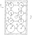
- Fig. 2 shows the frame 02 with the storage containers 05 preassembled therein and the two feed devices 06 for sand and soda in a view from above.
- the frame 02 can also contain a premixing device (not shown) in which the aggregates from the storage containers 05 are premixed.
- a premixing device not shown in which the aggregates from the storage containers 05 are premixed.
- Fig. 3 shows a second embodiment of a schematically represented batch plant 18.
- the batch plant 18 again comprises the frame 02 with the storage containers 05 and the feed devices 06 with the upstream storage container 07 and the conveyor device 08.
- the batch plant 18 further includes the frame 04 with the mixing device 12, which is in turn arranged above the conveyor bunker 14.
- a conveyor vehicle 19 is used in the batch plant 18 for metering the raw materials to be mixed.
- the conveyor vehicle 19 comprises a scale 20 with which the aggregates or sand and soda flowing down through the collecting funnel 09 can be measured.
- the conveyor vehicle 19 is coupled to the frame 02 in a dust-tight manner by means of a dust-collecting sleeve 24.
- the conveying vehicle 19 drives along a schematically represented roadway 21 to a platform above the frame 04.
- the conveying vehicle 19 can be an autonomously driving vehicle whose route is freely programmable in order to connect different system parts of the batch system with one another.
- the raw materials are drained from the scales 20 of the conveyor vehicle 19 into the mixing device 12 of the frame 04, where they are mixed with one another.
- the mixed batch then reaches the conveyor bunker 14, from where it is conveyed to the melting tank for melting the glass mass.
Description
Die Erfindung betrifft eine Gemengeanlage zur Herstellung eines aus mehreren Rohstoffen gemischten Glasgemenges nach dem Oberbegriff des Anspruchs 1.The invention relates to a batch plant for producing a glass batch mixed from several raw materials according to the preamble of claim 1.
Beim Herstellen von Glas müssen die dazu verwendeten Komponenten, insbesondere Sand und Soda, zuvor zu einem Glasgemenge gemischt werden. Das gemischte Glasgemenge kann dann anschließend einem Glasschmelzofen zugeführt und dort zu Glas geschmolzen werden. Das Glasgemenge kann dabei bspw. 60% Sand, 20% Soda und weitere 20% von verschiedenen Zuschlagsstoffen enthalten.When producing glass, the components used for this, in particular sand and soda, must first be mixed into a glass batch. The mixed glass batch can then be fed to a glass melting furnace and melted into glass there. The batch of glass can contain, for example, 60% sand, 20% soda and a further 20% of various additives.
Die bekannten Gemengeanlagen zur Herstellung von Glasgemenge umfassen für die verschiedenen zu vermischenden Rohstoffe jeweils einen Vorratsbehälter, indem die verschiedenen Rohstoffe bevorratet werden können. Weiter umfassen die Gemengeanlagen eine Dosiereinrichtung, mit der die zu mischenden Mengen der Rohstoffe zur Herstellung des gewünschten Gemenges dosiert werden können. Weiter umfassen die Gemengeanlagen eine Mischeinrichtung, in der die zumischenden Mengen der Rohstoffe gemischt werden können. Die verschiedenen Funktionsbestandteile der Gemengeanlagen werden dabei durch geeignete Fördereinrichtungen miteinander verbunden, um die Rohstoffe bzw. das Gemenge jeweils weiter fördern zu können.The known batch systems for producing batches of glass each include a storage container for the various raw materials to be mixed, in which the various raw materials can be stored. The batch systems also include a metering device with which the quantities of raw materials to be mixed can be metered for the production of the desired batch. The batch systems also include a mixing device in which the admixing quantities of the raw materials can be mixed. The various functional components of the batch systems are connected to one another by suitable conveying devices in order to be able to further convey the raw materials or the batch.
Bei den bekannten Gemengeanlagen handelt es sich um Großanlagen mit einer Herstellkapazität von mehreren 100 Tonen pro Tag. Diese Großanlagen werden als Einzelanlagen projektiert und dann beim jeweiligen Verwender unter Einsatz von Spezialisten und örtlicher Installationsfirmen aufgebaut. Diese Einzelprojektierung der zur Gemengeherstellung verwendeten Großanlagen hat vielerlei Nachteile. So müssen eine Vielzahl von fachfremden Installationsfirmen in die Projekte einbezogen werden, was aufgrund der Schnittstellen zu großen Problemen führen kann. Außerdem sind die bekannten Großanlagen zur Herstellung des Glasgemenges wenig flexibel, sodass Glas, bspw. Flaschen, nur in extrem hohen Stückzahlen hergestellt werden können. Auch können die bekannten Gemengeanlagen nicht vormontiert werden, sodass auf den Baustellen, die vielfach in abgelegenen Gegenden liegen, ein hoher Installationsaufwand anfällt. Ein späterer Rückbau der bekannten Gemengeanlagen, und die Gemengeanlage an einer anderen Stelle wieder aufzubauen, ist regelmäßig nicht möglich.The known batch plants are large plants with a production capacity of several 100 tons per day. These large-scale systems are planned as individual systems and then installed by the respective user with the help of specialists and local installation companies. This individual planning of the large systems used for batch production has many disadvantages. A large number of non-specialist installation companies have to be involved in the projects, which can lead to major problems due to the interfaces. In addition, the known large-scale systems for producing the glass batch are not very flexible, so that glass, for example bottles, can only be produced in extremely large numbers. The known batch systems cannot be preassembled either, so that the construction sites, which are often located in remote areas, require a high level of installation effort. A later dismantling of the known batch plants, and the batch plant to be rebuilt at a different location, is usually not possible.
Ausgehend von diesem Stand der Technik ist es Aufgabe der vorliegenden Erfindung, eine neue Gemengeanlage zur Herstellung eines Glasgemenges vorzuschlagen, die die Nachteile des vorbekannten Stands der Technik vermeidet.Based on this prior art, the object of the present invention is to propose a new batch plant for producing a glass batch which avoids the disadvantages of the known prior art.
Vorteilhafte Ausführungsformen der Erfindung sind Gegenstand der Unteransprüche.Advantageous embodiments of the invention are the subject of the subclaims.
Das Konzept der erfindungsgemäßen Gemengeanlage beruht auf dem Grundgedanken, dass die Gemengeanlage zumindest ein transportables Gestell umfasst. In diesem transportablen Gestell wird dann zumindest ein Vorratsbehälter und/oder zumindest eine Dosiereinrichtung und/oder zumindest eine Mischeinrichtung aufgenommen. Die in dem Gestell aufgenommenen Funktionsteile der Gemengeanlage können auf diese Weise beim Hersteller vormontiert und zusammen mit dem Gestell auf die Baustelle zur Errichtung der Gemengeanlage geliefert werden. Durch die im Gestell vormontierten Funktionselemente werden die auf der Baustelle miteinander zu verbindenden Schnittstellen der Gemengeanlage drastisch reduziert. Durch das Konzept der Vormontage der einzelnen Funktionsbestandteile der Gemengeanlage in jeweils einem transportablen Gestell lassen sich außerdem Gemengeanlagen gemäß einem Baukasten zusammenstellen. Insbesondere können dadurch auch kleinere Gemengeanlagen realisiert werden. Soweit eine Gemengeanlage dann am entsprechenden Standort nicht mehr benötigt wird, kann die Gemengeanlage zu einem späteren Zeitpunkt auch wieder demontiert und durch Abtransport der transportablen Gestelle an einem anderen Standort gebraucht werden.The concept of the batch plant according to the invention is based on the basic idea that the batch plant comprises at least one transportable frame. At least one storage container and / or at least one metering device and / or at least one mixing device is then received in this transportable frame. The functional parts of the batch plant accommodated in the frame can in this way be preassembled by the manufacturer and delivered together with the frame to the construction site for the erection of the batch plant. Due to the functional elements pre-assembled in the frame, the on-site Interfaces of the batch plant to be connected to one another drastically reduced Thanks to the concept of pre-assembling the individual functional components of the batch plant in a transportable frame, batch plants can also be assembled according to a modular system. In particular, smaller batch systems can also be implemented as a result. If a batch plant is then no longer required at the corresponding location, the batch plant can also be dismantled again at a later point in time and used at another location by removing the transportable racks.
Welche Funktionsbestandteile in jeweils einem Gestell der Gemengeanlage eingebaut sind, ist grundsätzlich beliebig. Gemäß einer ersten Ausführungsform ist es vorgesehen, dass in dem Gestell mehrere Vorratsbehälter vorgesehen sind, in denen die Zuschlagsstoffe für die Glasherstellung bevorratet werden können. Da die notwendigen Mengen zur Bevorratung von Zuschlagsstoffen im Vergleich zu Sand und Soda relativ gering sind, können die für die Bevorratung der Zuschlagsstoffe notwendigen Vorratsbehälter problemlos in das transportable Gestell integriert werden.Which functional components are installed in each frame of the batch plant is basically arbitrary. According to a first embodiment it is provided that several storage containers are provided in the frame, in which the additives for glass production can be stored. Since the quantities required to store aggregates are relatively small compared to sand and soda, the storage containers required for storing aggregates can be easily integrated into the transportable frame.
Die Vorratsmengen zur Bevorratung von Sand und Soda sind sehr groß, da bspw. eine Gemengeanlage mit einer Kapazität von 100 Tonnen pro Tag circa 60 Tonnen Sand bzw. 20 Tonnen Soda verbraucht. Die Integration solch großer Vorratsbehälter zur Bevorratung von Sand und Soda in die Gestelle der erfindungsgemäßen Gemengeanlage ist deshalb regelmäßig nicht sinnvoll. Um dennoch die Anzahl der notwendigen Schnittstellen bei der Installation der Gemengeanlage möglichst gering zu halten, ist es besonders vorteilhaft, wenn in einem Gestell zumindest eine Zuführeinrichtung vorgesehen ist, an der Sand und/oder Soda zugeführt werden kann. Dies bedeutet mit anderen Worten, dass das Gestell selbst keine Bevorratungseinrichtung zur Bevorratung von Sand bzw. Soda enthält. Vielmehr wird durch die Zuführeinrichtung in dem Gestell eine definierte Schnittstelle geschaffen, an der der Betreiber der Gemengeanlage dann Sand bzw. Soda in den Herstellungsprozess einführen kann. Vorratsbehälter zur Bevorratung von Sand und Soda werden dann vom Betreiber der Gemengeanlage baustellenseitig errichtet und dem entsprechenden Gestell mit der Zufuhreinrichtung vorgeordnet.The storage quantities for storing sand and soda are very large, since, for example, a batch plant with a capacity of 100 tonnes consumes around 60 tonnes of sand or 20 tonnes of soda per day. The integration of such large storage containers for storing sand and soda in the frames of the batch plant according to the invention is therefore generally not sensible. In order to keep the number of interfaces required when installing the batch plant as low as possible, it is particularly advantageous if at least one feed device is provided in a frame, to which sand and / or soda can be fed. In other words, this means that the frame itself does not contain any storage device for storing sand or soda. Rather, the feed device in the frame creates a defined interface at which the operator of the batch plant can then introduce sand or soda into the manufacturing process. Storage containers for storing sand and soda are then erected on site by the operator of the batch plant and placed in front of the corresponding frame with the feed device.
In welcher Art die Zufuhreinrichtung zur Zufuhr von Sand und/oder Soda ausgebildet ist, ist grundsätzlich beliebig. Als besonders vorteilhaft hat es sich erwiesen, wenn die Zufuhreinrichtung in der Art eines Einfülltrichters ausgebildet ist. Solche Einfülltrichter können baulich leicht aus dem bekannten Vorratsbehältern zur Bevorratung von Sand und/Soda abgeleitet werden, da es sich um den unteren Teil des Vorratsbehälters handelt.The type of feed device for feeding sand and / or soda is basically arbitrary. It has proven to be particularly advantageous if the feed device is designed in the manner of a filling funnel. Such filling funnels can easily be derived structurally from the known storage container for storing sand and / or soda, since it is the lower part of the storage container.
Die Zufuhreinrichtung selbst ist im Grundsatz nur zur Zuführung von Sand bzw. Soda in den Herstellungsprozess zur Herstellung des Gemenges vorgesehen. Um eine quasi kontinuierliche Zuführung von Sand bzw. Soda aus dem stationär errichteten Vorratsbehältern in die Zuführeinrichtung vermeiden zu können, ist es vorteilhaft, wenn in der Zuführeinrichtung, insbesondere in dem Einfülltrichter, eine geringe Menge von Sand bzw. Soda zwischengespeichert werden kann. Auf diese Weise kann dann die Zuführeinrichtung mit einer geeigneten Fördereinrichtung diskontinuierlich befüllt werden.In principle, the feed device itself is only intended for feeding sand or soda into the manufacturing process for producing the mixture. In order to be able to avoid a quasi continuous supply of sand or soda from the stationary storage container into the feed device, it is advantageous if a small amount of sand or soda can be temporarily stored in the feed device, in particular in the filling funnel. In this way, the feed device can then be filled discontinuously with a suitable conveyor device.
Um der Zuführeinrichtung Sand bzw. Soda aus einem vorgeordneten Vorratsbehälter zuführen zu können, kann zwischen dem Vorratsbehältern und der Zuführeinrichtung eine Fördereinrichtung vorgesehen werden. Eine solche Fördereinrichtung kann bspw. mittels eines Luftstroms Sand bzw. Soda aus dem jeweils vorgesehenen Vorratsbehälter entnehmen und in die Zuführeinrichtung einfördern. Durch Verwendung eines Luftstromsystems kann dabei auch eine Anhebung des Höhenniveaus vom Sand bzw. Soda realisiert werden, sodass Sand bzw. Soda anschließend während des eigentlichen Herstellprozesses unter ihrem Eigengewicht in der Anlage nach unten fließen.In order to be able to supply sand or soda to the supply device from an upstream storage container, a conveying device can be provided between the storage container and the supply device. Such a conveying device can, for example, remove sand or soda from the storage container provided in each case by means of an air stream and convey it into the feed device. By using an air flow system, the height level of the sand or soda can also be increased so that the sand or soda then flow downwards in the system under their own weight during the actual production process.
Bei den Zuschlagsstoffen ist es vielfach erforderlich, dass auch vergleichsweise geringe Mengen gemischt werden müssen. Um diese geringen Mengen möglichst gleichmäßig in das Gemenge einmischen zu können, ist es deshalb besonders vorteilhaft, wenn in dem Gestell auch eine Vormischeinrichtung vorgesehen ist, in der die Zuschlagsstoffe für die Glasherstellung vorgemischt werden können.In the case of aggregates, it is often necessary that even comparatively small amounts have to be mixed. In order to be able to mix these small amounts as evenly as possible into the mixture, it is therefore particularly advantageous if a premixing device is also provided in the frame, in which the additives for glass production can be premixed.
Bei der Herstellung des Glasgemenges stellt die dabei auftretende Staubentwicklung ein zunehmendes Problem dar, da Staubemissionen vielfach nur in sehr geringen Mengen toleriert werden. Zur Lösung dieses Problems ist es deshalb besonders vorteilhaft, wenn das Gestell eine geschlossene Außenwandung aufweist, dass einen geschlossenen Innenraum im Gestell staubdicht umschließt. Auf diese Weise kann eine staubdichte Hülle um das Gestell realisiert werden. Soweit mehrere Gestelle zusammengestellt werden, um die Gemengeanlage zu bilden, weisen die Gestelle nur an den Außenwandungen eine staubdichte Wandung auf, die gemeinsam die Außenhaut der miteinander kombinierten Gestelle bilden.During the production of the glass batch, the generation of dust that occurs during this process is an increasing problem, since dust emissions are often only tolerated in very small quantities. To solve this problem, it is therefore particularly advantageous if the frame has a closed outer wall that encloses a closed interior space in the frame in a dust-tight manner. In this way, a dust-tight cover can be created around the frame. If several racks are put together to form the batch plant, the racks only have a dust-tight wall on the outer walls, which together form the outer skin of the racks combined with one another.
Für die Anlagenkonfiguration der Gemengeanlage unter Verwendung der Gestelle gibt es verschiedenste Varianten. Besonders vorteilhaft ist es, wenn die Gemengeanlage mehrere transportable Gestelle umfasst, die dann jeweils eine oder mehrere Funktionseinheiten der Gemengeanlage umfassen. Durch Kombination der Gestelle können dann in einfacher Weise vormontierte Funktionselemente der Gemengeanlage auf die Baustelle angeliefert und gegebenenfalls auch wieder abtransportiert werden.There are various variants for the system configuration of the batch system using the racks. It is particularly advantageous if the batch plant comprises several transportable racks, which then each include one or more functional units of the batch plant. By combining the racks, preassembled functional elements of the batch system can then be delivered to the construction site in a simple manner and, if necessary, also transported away again.
Im Hinblick auf den einfachen Stofffluss der zu mischenden Rohstoffe in der Gemengeanlage ist es besonders vorteilhaft, wenn die verschiedenen Gestelle der Gemengeanlage übereinander anordenbar sind, insbesondere übereinander gestapelt werden können. Auf diese Weise kann dann eine Zufuhr der Rohstoffe von oben erfolgen, wobei die Rohstoffe dann während des eigentlichen Herstellprozesses zur Herstellung des Gemenges von oben nach unten fließen.With regard to the simple material flow of the raw materials to be mixed in the batch plant, it is particularly advantageous if the different frames of the batch plant can be arranged one above the other, in particular can be stacked one on top of the other. In this way, the raw materials can then be supplied from above, the raw materials then flowing from top to bottom during the actual production process for producing the mixture.
Gemäß einer zweiten Alternativen Anlagenkonfiguration wird das Gestell mit dem Vorratsbehältern aufgeständert, sodass zwischen der Unterseite des Gestells und einer Fahrbahn ein Beladeraum gebildet wird. In diesem Beladeraum kann dann ein Förderfahrzeug unter dem Gestell aufgenommen werden, sodass die Rohstoffe aus dem Vorratsbehältern in dem aufgeständerten Gestell von oben in einen entsprechenden Förderraum des Förderfahrzeuges fließen.According to a second alternative system configuration, the frame with the storage container is elevated so that a loading space is formed between the underside of the frame and a roadway. In this loading space, a conveyor vehicle can then be accommodated under the frame, so that the raw materials flow from the storage container in the raised frame from above into a corresponding conveyor room of the conveyor vehicle.
Zur Dosierung der jeweils zu mischenden Mengen der Rohstoffe kann in dem Förderfahrzeug eine Waage vorgesehen werden. Beim Zufördern der Rohstoffe aus den Vorratsbehältern in dem aufgestapelten Gestell wird dann die jeweils zugeförderten Menge eines einzelnen Rohstoffes abgewogen und die Zufuhr bei Erreichen der vorgesehenen Dosiermenge beendet. Sobald dann alle Rohstoffe in der ausreichenden Menge in den Laderaum des Förderfahrzeuges zugefördert sind, kann das Förderfahrzeug zu einem weiteren Gestell mit einer Mischeinrichtung fahren, um dort die Rohstoffe miteinander zu mischen und anschließend dem Glasschmelzprozess in der Glasschmelzpfanne zu zufördern.A scale can be provided in the conveyor vehicle for metering the quantities of raw materials to be mixed in each case. When the raw materials are fed in from the storage containers in the stacked frame, the respectively fed amount of an individual raw material is then weighed and the feed is terminated when the intended dosing amount is reached. As soon as all raw materials have been fed into the loading space of the conveyor vehicle in sufficient quantities, the conveyor vehicle can drive to another frame with a mixing device in order to mix the raw materials there and then feed them to the glass melting process in the glass melting pan.
Die Abmessungen der Gestelle zur Aufnahme der verschiedenen Funktionsteile der Gemengeanlage sind grundsätzlich beliebig. Um einen einfachen Transport der Gestelle auch zu weiter entfernten Baustellen in einfacher Weise realisieren zu können, ist es vorteilhaft, wenn die Gestelle der Gemengeanlage in einem Frachtcontainer anordenbar sind. Auf diese Weise können alle Gestelle mittels Containertransport zu der Baustelle transportiert und gegebenenfalls auch von dort wieder abtransportiert werden. Zwei Ausführungsformen der Erfindung sind in den Zeichnungen schematisiert dargestellt und werden nachfolgend beispielhaft erläutert.The dimensions of the racks for holding the various functional parts of the batch plant are basically arbitrary. In order to be able to easily transport the racks to construction sites that are further away, it is advantageous if the racks of the batch plant can be arranged in a freight container. In this way, all racks can be transported to the construction site by container transport and, if necessary, also transported away again from there. Two embodiments of the invention are shown schematically in the drawings and are explained below by way of example.
Es zeigen:
- Fig. 1
- eine erste Anlagenkonfiguration mit mehreren Gestellen zur Bildung einer Gemengeanlage in seitlicher Ansicht;
- Fig. 2
- das oberste Gestell der Gemengeanlage gemäß
Fig. 1 in Ansicht von oben; - Fig. 3
- eine zweite Anlagenkonfiguration einer Gemengeanlage mit mehreren Gestellen in seitlicher Ansicht.
- Fig. 1
- a first system configuration with several frames for forming a batch system in a side view;
- Fig. 2
- the top frame of the batch plant according to
Fig. 1 in top view; - Fig. 3
- a second system configuration of a batch system with several racks in a side view.
Das Gestell 02 ist zur Bevorratung eines Teils der verschiedener Rohstoffe, die Bestanteil des herzustellenden Gemenges sind, vorgesehen. Dazu sind im Gestell 02 sechs Vorratsbehälter 05 befestigt. Außerdem sind in dem Gestell 02 zwei in der Art von Einfülltrichter ausgebildete Zuführeinrichtung 06 vorgesehen, über die der Gemengeanlage 01 Sand bzw. Soda aus vorgeordneten Vorratsbehältern 07 zugefördert werden können. Dazu ist eine Zuführeinrichtung 08 vorgesehen, mit der Sand bzw. Soda aus dem entsprechenden Vorratsbehältern 07 entnommen und mittels eines Luftstroms in die Höhe gehoben und dann in die als Einfülltrichter ausgebildeten Zuführeinrichtungen 06 im Gestell 02 eingefördert werden. Die Zuschlagsstoffe aus den Vorratsbehältern 05 bzw. Sand und Soda, die über die Fördereinrichtung 08 in die Einfülltrichter 06 gefördert werden, können mit Austrageinrichtungen 22 und 23 dosiert ausgefördert werden. Die Einzelbestandteile fließen durch Öffnungen 15 und 16 nach unten ab und gelangen über einen Sammeltrichter 09 zum nächsten Gestell 03.The
Im Gestell 03 ist eine Waage 10 befestigt, mit der die Dosierung der Zuschlagsstoffe bzw. von Sand und Soda für das jeweils herzustellende Gemenge abgemessen werden können. Sobald die jeweils richtigen Mengen an Sand, Soda und Zuschlagsstoffen in der Waage 10 dosiert sind, werden die Austrageinrichtungen 22 und 23 gestoppt, so dass kein zusätzliches Material nachgefördert wird. Das zunächst noch ungemischte Gemenge wird dann über einen Sammeltrichter 11 dem darunter liegenden Gestell 04 zugeführt.In the
Im Gestell 04 ist eine Mischeinrichtung 12 befestigt, mit der die Zuschlagsstoffe, Sand und Soda miteinander vermischt werden. Das so hergestellte Gemenge gelangt anschließend über einen Sammeltrichter 13 in einen Förderbunker 14, von wo es mit geeigneten Fördermitteln in die Schmelzwanne zum Erschmelzen der Glasmasse gefördert werden kann.A mixing
Durch das Stapeln der Gestelle 02, 03 und 04 über dem Förderbunker 14 kann eine Gemengeanlage 01 sehr leicht und sehr schnell hergestellt werden. Die in den Gestellen 02, 03 und 04 vorhandenen Funktionsmodulen, nämlich die Vorratsbehälter 05, die Zufuhreinrichtung 06, die Waage 10 und die Mischeinrichtung 12 können mit den jeweiligen Sammeltrichtern 09, 11 und 13 beim Hersteller vormontiert und in Containern auf die entsprechende Baustelle zur Herstellung der Gemengeanlage vormontiert angeliefert werden. So weit erforderlich kann die Gemengeanlage 01 auch sehr einfach wieder demontiert und die Gestelle 02 zu einer anderen Baustelle transportiert werden.By stacking the
Zur Dosierung der zu mischenden Rohstoffe wird bei der Gemengeanlage 18 ein Förderfahrzeug 19 genutzt. Das Förderfahrzeug 19 umfasst eine Waage 20, mit der die durch den Sammeltrichter 09 nach unten fließenden Zuschlagsstoffe bzw. Sand und Soda abgemessen werden können. Um den unerwünschten Austritt von Staub zu vermindern, wird das Förderfahrzeug 19 mittels einer Staubfangmanschette 24 staubdicht an das Gestell 02 angekoppelt. Sobald alle für das zu herstellende Gemenge notwendigen Rohstoffe in die Waage 20 des Förderfahrzeuges 19 eingefördert sind, werden wiederum die Austrageinrichtungen 22 und 23 gestoppt, so dass kein zusätzliches Material nachgefördert wird.A
Dann fährt das Förderfahrzeug 19 entlang einer schematisiert dargestellten Fahrbahn 21 zu einem Podest oberhalb des Gestells 04. Bei dem Förderfahrzeug 19 kann es sich um ein autonom fahrendes Fahrzeug handeln, dessen Fahrweg frei programmierbar ist, um unterschiedliche Anlageteile der Gemengeanlage miteinander zu verbinden.Then the conveying
Über dem Gestell 04 werden die Rohstoffe aus der Waage 20 des Förderfahrzeugs 19 in die Mischeinrichtung 12 des Gestells 04 abgelassen und dort miteinander gemischt. Anschließend gelangt das gemischte Gemenge dann in den Förderbunker 14, von wo es zur Schmelzwanne zum erschmelzen der Glasmasse gefördert wird.Above the
Claims (14)
- A batch plant (01, 18) for producing a glass batch mixed of several raw materials, said batch plant (01, 18) having at least one storage container (05) in which a raw material is stored, having at least one proportioning means (10) by means of which the quantities of the raw materials to be mixed are proportioned, and having at least one mixing means (12) in which the quantities of the raw materials to be mixed are mixed,
characterised in that
the batch plant (01, 18) comprises at least one transportable stand (02, 03, 04), at least one storage container (05) and/or at least one proportioning means (10) and/or at least one mixing means (12) being placed in the stand (02, 03, 04). - The batch plant according to claim 1,
characterised in that
several storage containers (05) are provided in the stand, additives for the glass production being stored in said storage containers (05). - The batch plant according to claim 1 or 2,
characterised in that
at least one feeding means (06) is provided in the stand, sand and/or soda being fed at said feeding means (06). - The batch plant according to claim 3,
characterised in that
the feeding means (06) for feeding sand and/or soda is realised in the manner of a feed hopper. - The batch plant according to claim 3 or 4,
characterised in that
a small quantity of sand and/or soda is temporarily stored in the feeding means (06), in particular in the feed hopper. - The batch plant according to any one of claims 3 to 5, characterised in that
a conveyor (08) is arranged upstream of the feeding means (06), the conveyor (08) being able to convey sand and/or soda from a respectively assigned storage container (07) into the feeding means (06) of the stand (02). - The batch plant according to any one of claims 1 to 6, characterised in that
a premixing means is provided in the stand (02) having the storage containers (05), the additives for the glass production being mixed in said premixing means. - The batch plant according to any one of claims 1 to 7, characterised in that
the stand (02, 03, 04) has a closed outer wall which encloses an interior space in the stand (02, 03, 04) in a dust-tight manner. - The batch plant according to any one of claims 1 to 8, characterised in that
the batch plant (01, 18) comprises several transportable stands (02, 03, 04) in each of which at least one storage container (05) and/or at last one proportioning means (10) and/or at least one mixing means (12) is/are placed. - The batch plant according to claim 9,
characterised in that
the different stands (02, 03, 04) of the batch plant (01) are arranged above each other. - The batch plant according to claim 10,
characterised in that
the different stands (02, 03, 04) of the batch plant (01) are stacked on top of each other. - The batch plant according to any one of claims 1 to 11, characterised in that
the stand (02) having at least one storage container (05) is elevated such that a loading space is formed between the bottom side of the stand (02) and a roadway (21), a conveyor vehicle (19) to be loaded being placed under the stand (02) in said loading space. - The batch plant according to claim 12,
characterised in that
the conveyor vehicle (19) comprises a weighing balance (20) in which the quantities of the raw materials to be mixed are weighed. - The batch plant according to any one of claims 1 to 13, characterised in that
the stand (02, 03, 04) of the batch plant (01, 18) is arranged in a freight container.
Applications Claiming Priority (1)
| Application Number | Priority Date | Filing Date | Title |
|---|---|---|---|
| DE202019101523.3U DE202019101523U1 (en) | 2019-03-18 | 2019-03-18 | Batch plant for the production of a glass batch |
Publications (2)
| Publication Number | Publication Date |
|---|---|
| EP3712117A1 EP3712117A1 (en) | 2020-09-23 |
| EP3712117B1 true EP3712117B1 (en) | 2021-07-28 |
Family
ID=66137995
Family Applications (1)
| Application Number | Title | Priority Date | Filing Date |
|---|---|---|---|
| EP20161989.7A Active EP3712117B1 (en) | 2019-03-18 | 2020-03-10 | Batch installation for making a glass batch |
Country Status (2)
| Country | Link |
|---|---|
| EP (1) | EP3712117B1 (en) |
| DE (2) | DE202019101523U1 (en) |
Families Citing this family (1)
| Publication number | Priority date | Publication date | Assignee | Title |
|---|---|---|---|---|
| DE102020122681A1 (en) | 2020-08-31 | 2022-03-03 | Zippe Gmbh U. Co. Kg | Modular dust-proof batch plant |
Citations (13)
| Publication number | Priority date | Publication date | Assignee | Title |
|---|---|---|---|---|
| US1473008A (en) | 1922-03-13 | 1923-11-06 | Libbey Owens Sheet Glass Co | Raw-material conveyer for feeding glass furnaces |
| CH445734A (en) | 1965-02-05 | 1967-10-31 | Libbey Owens Ford Glass Co | Method and device for feeding measured quantities of raw glass materials and glass scrap into a glass melting furnace |
| DE2043372A1 (en) | 1969-09-08 | 1971-03-11 | Owens Corning Fiberglass Corp | Dosing process and equipment for carrying out this process |
| US3823920A (en) | 1971-02-12 | 1974-07-16 | Owens Illinois Inc | Feeding wet glass batch |
| DE3036968A1 (en) | 1980-10-01 | 1982-04-22 | Meyer Maschinen- und Wiegeapparatebau GmbH & CO KG, 5202 Hennef | Continually controlling mixing process by multiple weighings - and comparison with values needed for desired properties |
| US4775275A (en) | 1987-04-13 | 1988-10-04 | Perry L F | Mobile batch plants |
| US5785421A (en) | 1996-10-22 | 1998-07-28 | Milek; Robert C. | Mobile modular concrete batch plant |
| DE19909896C2 (en) | 1999-03-06 | 2001-11-08 | Stefan Soine | Method and device for producing a mixture of starting materials |
| WO2004098763A2 (en) | 2003-05-12 | 2004-11-18 | Kurt Steinwald | Device for dosing and mixing powdery materials |
| JP2006231712A (en) | 2005-02-25 | 2006-09-07 | Marumi:Kk | Pelletizer |
| EP1520672B1 (en) | 1999-01-19 | 2006-12-13 | Heilit+Woerner Bau GmbH | Container concrete mixing plant |
| DE102013000840B3 (en) | 2013-01-21 | 2014-07-17 | Rudolf Baumann | Gravimetric dosing system for coarse and fine dosage of bulk material components e.g. chemical raw materials, has closure element that is lifted to open cover and material component in discharging device is gravimetrically dosed |
| KR101819468B1 (en) | 2017-06-26 | 2018-01-17 | 신두국 | Batch plant for glass raw material |
-
2019
- 2019-03-18 DE DE202019101523.3U patent/DE202019101523U1/en active Active
- 2019-11-07 DE DE102019130003.7A patent/DE102019130003A1/en active Pending
-
2020
- 2020-03-10 EP EP20161989.7A patent/EP3712117B1/en active Active
Patent Citations (13)
| Publication number | Priority date | Publication date | Assignee | Title |
|---|---|---|---|---|
| US1473008A (en) | 1922-03-13 | 1923-11-06 | Libbey Owens Sheet Glass Co | Raw-material conveyer for feeding glass furnaces |
| CH445734A (en) | 1965-02-05 | 1967-10-31 | Libbey Owens Ford Glass Co | Method and device for feeding measured quantities of raw glass materials and glass scrap into a glass melting furnace |
| DE2043372A1 (en) | 1969-09-08 | 1971-03-11 | Owens Corning Fiberglass Corp | Dosing process and equipment for carrying out this process |
| US3823920A (en) | 1971-02-12 | 1974-07-16 | Owens Illinois Inc | Feeding wet glass batch |
| DE3036968A1 (en) | 1980-10-01 | 1982-04-22 | Meyer Maschinen- und Wiegeapparatebau GmbH & CO KG, 5202 Hennef | Continually controlling mixing process by multiple weighings - and comparison with values needed for desired properties |
| US4775275A (en) | 1987-04-13 | 1988-10-04 | Perry L F | Mobile batch plants |
| US5785421A (en) | 1996-10-22 | 1998-07-28 | Milek; Robert C. | Mobile modular concrete batch plant |
| EP1520672B1 (en) | 1999-01-19 | 2006-12-13 | Heilit+Woerner Bau GmbH | Container concrete mixing plant |
| DE19909896C2 (en) | 1999-03-06 | 2001-11-08 | Stefan Soine | Method and device for producing a mixture of starting materials |
| WO2004098763A2 (en) | 2003-05-12 | 2004-11-18 | Kurt Steinwald | Device for dosing and mixing powdery materials |
| JP2006231712A (en) | 2005-02-25 | 2006-09-07 | Marumi:Kk | Pelletizer |
| DE102013000840B3 (en) | 2013-01-21 | 2014-07-17 | Rudolf Baumann | Gravimetric dosing system for coarse and fine dosage of bulk material components e.g. chemical raw materials, has closure element that is lifted to open cover and material component in discharging device is gravimetrically dosed |
| KR101819468B1 (en) | 2017-06-26 | 2018-01-17 | 신두국 | Batch plant for glass raw material |
Also Published As
| Publication number | Publication date |
|---|---|
| EP3712117A1 (en) | 2020-09-23 |
| DE102019130003A1 (en) | 2020-09-24 |
| DE202019101523U1 (en) | 2019-03-22 |
Similar Documents
| Publication | Publication Date | Title |
|---|---|---|
| DE102010035893B3 (en) | Feeding device for glass melting plants and method for inserting particulate feed material | |
| AT504291B1 (en) | APPENDIX FOR THE PRODUCTION OF DRY AND WET MIXTURES | |
| EP1622707B1 (en) | Device for dosing and mixing powdery materials | |
| WO2007054084A2 (en) | Apparatus for the production of a mixture of different bulk material components | |
| EP3712117B1 (en) | Batch installation for making a glass batch | |
| DE3245443C2 (en) | Device and process for conditioning radioactive waste suitable for disposal | |
| EP0216006A2 (en) | Method and apparatus for admixing a finely dispersed dye with a plastics granulate | |
| DE1947219A1 (en) | Apparatus for handling mold charge quantities of molten glass | |
| DE3637408C2 (en) | ||
| DE1914541A1 (en) | Method and apparatus for batch-wise rapid compounding of comminuted materials | |
| DE19614688C2 (en) | Device for producing a mixture of different bulk material components | |
| EP1616683A2 (en) | Plant for manufacturing and processing of a mixture to be sprayed in wet condition | |
| DE3641947A1 (en) | Process for preparing sprayed mortar or sprayed concrete and system for carrying out the process | |
| DE2724928A1 (en) | Blending stored materials in double silos - having mixer silo with homogenising blending silo mounted below it with feed via controlled spouting inlets | |
| DE102006043596B3 (en) | Conveying device for a material mixture from components, comprises mixing container having a mixing device for the materials, discharge device for discharging the materials from the mixing container, and flow mixer for different components | |
| DE2422963B1 (en) | Pneumatic mixing and conveying system for (volatile bulk goods | |
| DE202016003241U1 (en) | Plant for mixing concrete | |
| DE102019122041A1 (en) | Mixing plant for the production of a building mix from a binder, a bulk material and an aqueous liquid | |
| EP0595240B1 (en) | Dosing apparatus on a plastics extruder | |
| DE2844589A1 (en) | Bulk material mixing silo - has central storage hopper enclosed by annular one discharging into common main | |
| EP3038961A1 (en) | Metering device with storage container and discharge device | |
| DE3709236A1 (en) | Device for the production and conveying of floor screed | |
| DE102020122681A1 (en) | Modular dust-proof batch plant | |
| DE2249150A1 (en) | Concrete mixing process - premixing constituents other than cement with water prior to cement addn | |
| DE3342465C2 (en) |
Legal Events
| Date | Code | Title | Description |
|---|---|---|---|
| PUAI | Public reference made under article 153(3) epc to a published international application that has entered the european phase |
Free format text: ORIGINAL CODE: 0009012 |
|
| STAA | Information on the status of an ep patent application or granted ep patent |
Free format text: STATUS: THE APPLICATION HAS BEEN PUBLISHED |
|
| AK | Designated contracting states |
Kind code of ref document: A1 Designated state(s): AL AT BE BG CH CY CZ DE DK EE ES FI FR GB GR HR HU IE IS IT LI LT LU LV MC MK MT NL NO PL PT RO RS SE SI SK SM TR |
|
| AX | Request for extension of the european patent |
Extension state: BA ME |
|
| STAA | Information on the status of an ep patent application or granted ep patent |
Free format text: STATUS: REQUEST FOR EXAMINATION WAS MADE |
|
| 17P | Request for examination filed |
Effective date: 20201007 |
|
| RBV | Designated contracting states (corrected) |
Designated state(s): AL AT BE BG CH CY CZ DE DK EE ES FI FR GB GR HR HU IE IS IT LI LT LU LV MC MK MT NL NO PL PT RO RS SE SI SK SM TR |
|
| GRAP | Despatch of communication of intention to grant a patent |
Free format text: ORIGINAL CODE: EPIDOSNIGR1 |
|
| STAA | Information on the status of an ep patent application or granted ep patent |
Free format text: STATUS: GRANT OF PATENT IS INTENDED |
|
| INTG | Intention to grant announced |
Effective date: 20201222 |
|
| GRAS | Grant fee paid |
Free format text: ORIGINAL CODE: EPIDOSNIGR3 |
|
| GRAA | (expected) grant |
Free format text: ORIGINAL CODE: 0009210 |
|
| STAA | Information on the status of an ep patent application or granted ep patent |
Free format text: STATUS: THE PATENT HAS BEEN GRANTED |
|
| AK | Designated contracting states |
Kind code of ref document: B1 Designated state(s): AL AT BE BG CH CY CZ DE DK EE ES FI FR GB GR HR HU IE IS IT LI LT LU LV MC MK MT NL NO PL PT RO RS SE SI SK SM TR |
|
| REG | Reference to a national code |
Ref country code: GB Ref legal event code: FG4D Free format text: NOT ENGLISH |
|
| REG | Reference to a national code |
Ref country code: CH Ref legal event code: EP |
|
| REG | Reference to a national code |
Ref country code: DE Ref legal event code: R096 Ref document number: 502020000105 Country of ref document: DE |
|
| REG | Reference to a national code |
Ref country code: AT Ref legal event code: REF Ref document number: 1414608 Country of ref document: AT Kind code of ref document: T Effective date: 20210815 |
|
| REG | Reference to a national code |
Ref country code: IE Ref legal event code: FG4D Free format text: LANGUAGE OF EP DOCUMENT: GERMAN |
|
| REG | Reference to a national code |
Ref country code: LT Ref legal event code: MG9D |
|
| REG | Reference to a national code |
Ref country code: NL Ref legal event code: MP Effective date: 20210728 |
|
| PG25 | Lapsed in a contracting state [announced via postgrant information from national office to epo] |
Ref country code: BG Free format text: LAPSE BECAUSE OF FAILURE TO SUBMIT A TRANSLATION OF THE DESCRIPTION OR TO PAY THE FEE WITHIN THE PRESCRIBED TIME-LIMIT Effective date: 20211028 Ref country code: LT Free format text: LAPSE BECAUSE OF FAILURE TO SUBMIT A TRANSLATION OF THE DESCRIPTION OR TO PAY THE FEE WITHIN THE PRESCRIBED TIME-LIMIT Effective date: 20210728 Ref country code: HR Free format text: LAPSE BECAUSE OF FAILURE TO SUBMIT A TRANSLATION OF THE DESCRIPTION OR TO PAY THE FEE WITHIN THE PRESCRIBED TIME-LIMIT Effective date: 20210728 Ref country code: FI Free format text: LAPSE BECAUSE OF FAILURE TO SUBMIT A TRANSLATION OF THE DESCRIPTION OR TO PAY THE FEE WITHIN THE PRESCRIBED TIME-LIMIT Effective date: 20210728 Ref country code: NL Free format text: LAPSE BECAUSE OF FAILURE TO SUBMIT A TRANSLATION OF THE DESCRIPTION OR TO PAY THE FEE WITHIN THE PRESCRIBED TIME-LIMIT Effective date: 20210728 Ref country code: NO Free format text: LAPSE BECAUSE OF FAILURE TO SUBMIT A TRANSLATION OF THE DESCRIPTION OR TO PAY THE FEE WITHIN THE PRESCRIBED TIME-LIMIT Effective date: 20211028 Ref country code: PT Free format text: LAPSE BECAUSE OF FAILURE TO SUBMIT A TRANSLATION OF THE DESCRIPTION OR TO PAY THE FEE WITHIN THE PRESCRIBED TIME-LIMIT Effective date: 20211129 Ref country code: ES Free format text: LAPSE BECAUSE OF FAILURE TO SUBMIT A TRANSLATION OF THE DESCRIPTION OR TO PAY THE FEE WITHIN THE PRESCRIBED TIME-LIMIT Effective date: 20210728 Ref country code: RS Free format text: LAPSE BECAUSE OF FAILURE TO SUBMIT A TRANSLATION OF THE DESCRIPTION OR TO PAY THE FEE WITHIN THE PRESCRIBED TIME-LIMIT Effective date: 20210728 Ref country code: SE Free format text: LAPSE BECAUSE OF FAILURE TO SUBMIT A TRANSLATION OF THE DESCRIPTION OR TO PAY THE FEE WITHIN THE PRESCRIBED TIME-LIMIT Effective date: 20210728 |
|
| PG25 | Lapsed in a contracting state [announced via postgrant information from national office to epo] |
Ref country code: PL Free format text: LAPSE BECAUSE OF FAILURE TO SUBMIT A TRANSLATION OF THE DESCRIPTION OR TO PAY THE FEE WITHIN THE PRESCRIBED TIME-LIMIT Effective date: 20210728 Ref country code: LV Free format text: LAPSE BECAUSE OF FAILURE TO SUBMIT A TRANSLATION OF THE DESCRIPTION OR TO PAY THE FEE WITHIN THE PRESCRIBED TIME-LIMIT Effective date: 20210728 Ref country code: GR Free format text: LAPSE BECAUSE OF FAILURE TO SUBMIT A TRANSLATION OF THE DESCRIPTION OR TO PAY THE FEE WITHIN THE PRESCRIBED TIME-LIMIT Effective date: 20211029 |
|
| REG | Reference to a national code |
Ref country code: DE Ref legal event code: R026 Ref document number: 502020000105 Country of ref document: DE |
|
| PG25 | Lapsed in a contracting state [announced via postgrant information from national office to epo] |
Ref country code: DK Free format text: LAPSE BECAUSE OF FAILURE TO SUBMIT A TRANSLATION OF THE DESCRIPTION OR TO PAY THE FEE WITHIN THE PRESCRIBED TIME-LIMIT Effective date: 20210728 |
|
| PLBI | Opposition filed |
Free format text: ORIGINAL CODE: 0009260 |
|
| PLAX | Notice of opposition and request to file observation + time limit sent |
Free format text: ORIGINAL CODE: EPIDOSNOBS2 |
|
| PG25 | Lapsed in a contracting state [announced via postgrant information from national office to epo] |
Ref country code: SM Free format text: LAPSE BECAUSE OF FAILURE TO SUBMIT A TRANSLATION OF THE DESCRIPTION OR TO PAY THE FEE WITHIN THE PRESCRIBED TIME-LIMIT Effective date: 20210728 Ref country code: SK Free format text: LAPSE BECAUSE OF FAILURE TO SUBMIT A TRANSLATION OF THE DESCRIPTION OR TO PAY THE FEE WITHIN THE PRESCRIBED TIME-LIMIT Effective date: 20210728 Ref country code: RO Free format text: LAPSE BECAUSE OF FAILURE TO SUBMIT A TRANSLATION OF THE DESCRIPTION OR TO PAY THE FEE WITHIN THE PRESCRIBED TIME-LIMIT Effective date: 20210728 Ref country code: EE Free format text: LAPSE BECAUSE OF FAILURE TO SUBMIT A TRANSLATION OF THE DESCRIPTION OR TO PAY THE FEE WITHIN THE PRESCRIBED TIME-LIMIT Effective date: 20210728 Ref country code: CZ Free format text: LAPSE BECAUSE OF FAILURE TO SUBMIT A TRANSLATION OF THE DESCRIPTION OR TO PAY THE FEE WITHIN THE PRESCRIBED TIME-LIMIT Effective date: 20210728 Ref country code: AL Free format text: LAPSE BECAUSE OF FAILURE TO SUBMIT A TRANSLATION OF THE DESCRIPTION OR TO PAY THE FEE WITHIN THE PRESCRIBED TIME-LIMIT Effective date: 20210728 |
|
| 26 | Opposition filed |
Opponent name: EME GMBH Effective date: 20220428 |
|
| PG25 | Lapsed in a contracting state [announced via postgrant information from national office to epo] |
Ref country code: IT Free format text: LAPSE BECAUSE OF FAILURE TO SUBMIT A TRANSLATION OF THE DESCRIPTION OR TO PAY THE FEE WITHIN THE PRESCRIBED TIME-LIMIT Effective date: 20210728 |
|
| PLBB | Reply of patent proprietor to notice(s) of opposition received |
Free format text: ORIGINAL CODE: EPIDOSNOBS3 |
|
| PG25 | Lapsed in a contracting state [announced via postgrant information from national office to epo] |
Ref country code: MC Free format text: LAPSE BECAUSE OF FAILURE TO SUBMIT A TRANSLATION OF THE DESCRIPTION OR TO PAY THE FEE WITHIN THE PRESCRIBED TIME-LIMIT Effective date: 20210728 |
|
| REG | Reference to a national code |
Ref country code: BE Ref legal event code: MM Effective date: 20220331 |
|
| PG25 | Lapsed in a contracting state [announced via postgrant information from national office to epo] |
Ref country code: LU Free format text: LAPSE BECAUSE OF NON-PAYMENT OF DUE FEES Effective date: 20220310 Ref country code: IE Free format text: LAPSE BECAUSE OF NON-PAYMENT OF DUE FEES Effective date: 20220310 Ref country code: FR Free format text: LAPSE BECAUSE OF NON-PAYMENT OF DUE FEES Effective date: 20220331 |
|
| PLAB | Opposition data, opponent's data or that of the opponent's representative modified |
Free format text: ORIGINAL CODE: 0009299OPPO |
|
| PG25 | Lapsed in a contracting state [announced via postgrant information from national office to epo] |
Ref country code: BE Free format text: LAPSE BECAUSE OF NON-PAYMENT OF DUE FEES Effective date: 20220331 |
|
| R26 | Opposition filed (corrected) |
Opponent name: EME GMBH Effective date: 20220428 |
|
| PGFP | Annual fee paid to national office [announced via postgrant information from national office to epo] |
Ref country code: DE Payment date: 20230131 Year of fee payment: 4 |
|
| P01 | Opt-out of the competence of the unified patent court (upc) registered |
Effective date: 20230517 |
|
| REG | Reference to a national code |
Ref country code: CH Ref legal event code: PL |
|
| PG25 | Lapsed in a contracting state [announced via postgrant information from national office to epo] |
Ref country code: LI Free format text: LAPSE BECAUSE OF NON-PAYMENT OF DUE FEES Effective date: 20230331 Ref country code: CH Free format text: LAPSE BECAUSE OF NON-PAYMENT OF DUE FEES Effective date: 20230331 |
|
| RDAF | Communication despatched that patent is revoked |
Free format text: ORIGINAL CODE: EPIDOSNREV1 |