EP3711729A1 - Articles absorbants - Google Patents
Articles absorbants Download PDFInfo
- Publication number
- EP3711729A1 EP3711729A1 EP19164452.5A EP19164452A EP3711729A1 EP 3711729 A1 EP3711729 A1 EP 3711729A1 EP 19164452 A EP19164452 A EP 19164452A EP 3711729 A1 EP3711729 A1 EP 3711729A1
- Authority
- EP
- European Patent Office
- Prior art keywords
- absorbent
- core
- channel
- absorbent core
- absorbent article
- Prior art date
- Legal status (The legal status is an assumption and is not a legal conclusion. Google has not performed a legal analysis and makes no representation as to the accuracy of the status listed.)
- Granted
Links
- 230000002745 absorbent Effects 0.000 title claims abstract description 442
- 239000002250 absorbent Substances 0.000 title claims abstract description 442
- 239000000463 material Substances 0.000 claims abstract description 216
- 238000009826 distribution Methods 0.000 claims abstract description 116
- 239000007788 liquid Substances 0.000 claims abstract description 88
- 229920000247 superabsorbent polymer Polymers 0.000 claims abstract description 50
- 229920002994 synthetic fiber Polymers 0.000 claims abstract description 19
- 239000012209 synthetic fiber Substances 0.000 claims abstract description 19
- 229920003043 Cellulose fiber Polymers 0.000 claims abstract description 11
- 239000004583 superabsorbent polymers (SAPs) Substances 0.000 claims abstract description 10
- 239000000835 fiber Substances 0.000 claims description 87
- -1 polypropylene Polymers 0.000 claims description 31
- 239000004743 Polypropylene Substances 0.000 claims description 23
- 229920001155 polypropylene Polymers 0.000 claims description 23
- 239000011148 porous material Substances 0.000 claims description 12
- 239000004094 surface-active agent Substances 0.000 claims description 4
- 239000011162 core material Substances 0.000 description 279
- 239000010410 layer Substances 0.000 description 126
- 239000012530 fluid Substances 0.000 description 120
- 239000000853 adhesive Substances 0.000 description 76
- 230000001070 adhesive effect Effects 0.000 description 75
- 238000000034 method Methods 0.000 description 48
- 239000002245 particle Substances 0.000 description 39
- 239000012792 core layer Substances 0.000 description 31
- 239000000203 mixture Substances 0.000 description 29
- 238000010521 absorption reaction Methods 0.000 description 26
- 230000008901 benefit Effects 0.000 description 25
- 210000000416 exudates and transudate Anatomy 0.000 description 25
- 230000008569 process Effects 0.000 description 24
- 239000000758 substrate Substances 0.000 description 19
- 229920000642 polymer Polymers 0.000 description 17
- 238000012360 testing method Methods 0.000 description 17
- 239000004745 nonwoven fabric Substances 0.000 description 15
- XLYOFNOQVPJJNP-UHFFFAOYSA-N water Substances O XLYOFNOQVPJJNP-UHFFFAOYSA-N 0.000 description 14
- FAPWRFPIFSIZLT-UHFFFAOYSA-M Sodium chloride Chemical compound [Na+].[Cl-] FAPWRFPIFSIZLT-UHFFFAOYSA-M 0.000 description 13
- 208000028659 discharge Diseases 0.000 description 11
- 239000000243 solution Substances 0.000 description 10
- 238000009736 wetting Methods 0.000 description 10
- 206010021639 Incontinence Diseases 0.000 description 9
- 239000011230 binding agent Substances 0.000 description 9
- 239000006260 foam Substances 0.000 description 9
- 230000014759 maintenance of location Effects 0.000 description 9
- 229920006395 saturated elastomer Polymers 0.000 description 9
- 238000004891 communication Methods 0.000 description 8
- 239000013013 elastic material Substances 0.000 description 8
- 239000004744 fabric Substances 0.000 description 8
- 238000005304 joining Methods 0.000 description 8
- 235000002639 sodium chloride Nutrition 0.000 description 8
- 230000008961 swelling Effects 0.000 description 8
- 239000002131 composite material Substances 0.000 description 7
- 229920001577 copolymer Polymers 0.000 description 7
- 229920001200 poly(ethylene-vinyl acetate) Polymers 0.000 description 7
- 239000011780 sodium chloride Substances 0.000 description 7
- 238000010998 test method Methods 0.000 description 7
- 238000012549 training Methods 0.000 description 7
- 230000000007 visual effect Effects 0.000 description 7
- 229920002943 EPDM rubber Polymers 0.000 description 6
- 230000004888 barrier function Effects 0.000 description 6
- 230000015572 biosynthetic process Effects 0.000 description 6
- DQXBYHZEEUGOBF-UHFFFAOYSA-N but-3-enoic acid;ethene Chemical compound C=C.OC(=O)CC=C DQXBYHZEEUGOBF-UHFFFAOYSA-N 0.000 description 6
- 230000008859 change Effects 0.000 description 6
- 229920001971 elastomer Polymers 0.000 description 6
- 239000005038 ethylene vinyl acetate Substances 0.000 description 6
- 230000002209 hydrophobic effect Effects 0.000 description 6
- 239000002985 plastic film Substances 0.000 description 6
- 229920006255 plastic film Polymers 0.000 description 6
- 239000000126 substance Substances 0.000 description 6
- 239000004831 Hot glue Substances 0.000 description 5
- 229920001131 Pulp (paper) Polymers 0.000 description 5
- 238000007906 compression Methods 0.000 description 5
- 230000006835 compression Effects 0.000 description 5
- 238000004049 embossing Methods 0.000 description 5
- 239000000499 gel Substances 0.000 description 5
- 230000006872 improvement Effects 0.000 description 5
- 238000004519 manufacturing process Methods 0.000 description 5
- 239000011159 matrix material Substances 0.000 description 5
- 230000007246 mechanism Effects 0.000 description 5
- 229920001169 thermoplastic Polymers 0.000 description 5
- 238000012876 topography Methods 0.000 description 5
- 210000002700 urine Anatomy 0.000 description 5
- 229920000297 Rayon Polymers 0.000 description 4
- 229920002472 Starch Polymers 0.000 description 4
- 230000000903 blocking effect Effects 0.000 description 4
- 238000009472 formulation Methods 0.000 description 4
- 238000002844 melting Methods 0.000 description 4
- 230000008018 melting Effects 0.000 description 4
- 229910052751 metal Inorganic materials 0.000 description 4
- 239000002184 metal Substances 0.000 description 4
- 230000035699 permeability Effects 0.000 description 4
- 229920003023 plastic Polymers 0.000 description 4
- 239000004033 plastic Substances 0.000 description 4
- 229920000728 polyester Polymers 0.000 description 4
- 239000002994 raw material Substances 0.000 description 4
- 229920005989 resin Polymers 0.000 description 4
- 239000011347 resin Substances 0.000 description 4
- 239000005060 rubber Substances 0.000 description 4
- 238000007493 shaping process Methods 0.000 description 4
- 239000008107 starch Substances 0.000 description 4
- 235000019698 starch Nutrition 0.000 description 4
- 239000004416 thermosoftening plastic Substances 0.000 description 4
- 229920000742 Cotton Polymers 0.000 description 3
- VVQNEPGJFQJSBK-UHFFFAOYSA-N Methyl methacrylate Chemical compound COC(=O)C(C)=C VVQNEPGJFQJSBK-UHFFFAOYSA-N 0.000 description 3
- 229920005372 Plexiglas® Polymers 0.000 description 3
- 239000004698 Polyethylene Substances 0.000 description 3
- 210000001015 abdomen Anatomy 0.000 description 3
- 230000009471 action Effects 0.000 description 3
- 238000004026 adhesive bonding Methods 0.000 description 3
- 239000007864 aqueous solution Substances 0.000 description 3
- 239000002585 base Substances 0.000 description 3
- 230000009286 beneficial effect Effects 0.000 description 3
- 230000005540 biological transmission Effects 0.000 description 3
- 229920001400 block copolymer Polymers 0.000 description 3
- 229920002678 cellulose Polymers 0.000 description 3
- 239000001913 cellulose Substances 0.000 description 3
- 230000000295 complement effect Effects 0.000 description 3
- 239000000470 constituent Substances 0.000 description 3
- 238000010276 construction Methods 0.000 description 3
- 230000000694 effects Effects 0.000 description 3
- 238000002347 injection Methods 0.000 description 3
- 239000007924 injection Substances 0.000 description 3
- 229910010272 inorganic material Inorganic materials 0.000 description 3
- 239000011147 inorganic material Substances 0.000 description 3
- 210000004914 menses Anatomy 0.000 description 3
- 229920002401 polyacrylamide Polymers 0.000 description 3
- 229920000573 polyethylene Polymers 0.000 description 3
- 229920002635 polyurethane Polymers 0.000 description 3
- 239000004814 polyurethane Substances 0.000 description 3
- 239000000843 powder Substances 0.000 description 3
- 239000002964 rayon Substances 0.000 description 3
- 238000007789 sealing Methods 0.000 description 3
- 239000003381 stabilizer Substances 0.000 description 3
- 229920001059 synthetic polymer Polymers 0.000 description 3
- SMZOUWXMTYCWNB-UHFFFAOYSA-N 2-(2-methoxy-5-methylphenyl)ethanamine Chemical compound COC1=CC=C(C)C=C1CCN SMZOUWXMTYCWNB-UHFFFAOYSA-N 0.000 description 2
- NIXOWILDQLNWCW-UHFFFAOYSA-N 2-Propenoic acid Natural products OC(=O)C=C NIXOWILDQLNWCW-UHFFFAOYSA-N 0.000 description 2
- 235000001674 Agaricus brunnescens Nutrition 0.000 description 2
- 229920002134 Carboxymethyl cellulose Polymers 0.000 description 2
- 229920002153 Hydroxypropyl cellulose Polymers 0.000 description 2
- 241000238367 Mya arenaria Species 0.000 description 2
- VYPSYNLAJGMNEJ-UHFFFAOYSA-N Silicium dioxide Chemical compound O=[Si]=O VYPSYNLAJGMNEJ-UHFFFAOYSA-N 0.000 description 2
- 229920002125 Sokalan® Polymers 0.000 description 2
- 229920002522 Wood fibre Polymers 0.000 description 2
- 239000000654 additive Substances 0.000 description 2
- 238000005054 agglomeration Methods 0.000 description 2
- 230000002776 aggregation Effects 0.000 description 2
- 229910052783 alkali metal Inorganic materials 0.000 description 2
- 239000003963 antioxidant agent Substances 0.000 description 2
- 238000005452 bending Methods 0.000 description 2
- 239000008280 blood Substances 0.000 description 2
- 210000004369 blood Anatomy 0.000 description 2
- 210000001124 body fluid Anatomy 0.000 description 2
- 239000010839 body fluid Substances 0.000 description 2
- 230000036760 body temperature Effects 0.000 description 2
- 239000001768 carboxy methyl cellulose Substances 0.000 description 2
- 235000010948 carboxy methyl cellulose Nutrition 0.000 description 2
- 239000008112 carboxymethyl-cellulose Substances 0.000 description 2
- 230000005465 channeling Effects 0.000 description 2
- 239000003795 chemical substances by application Substances 0.000 description 2
- 238000004040 coloring Methods 0.000 description 2
- 229920006147 copolyamide elastomer Polymers 0.000 description 2
- 238000000151 deposition Methods 0.000 description 2
- 230000009977 dual effect Effects 0.000 description 2
- 239000000806 elastomer Substances 0.000 description 2
- HQQADJVZYDDRJT-UHFFFAOYSA-N ethene;prop-1-ene Chemical group C=C.CC=C HQQADJVZYDDRJT-UHFFFAOYSA-N 0.000 description 2
- 238000011156 evaluation Methods 0.000 description 2
- 230000002550 fecal effect Effects 0.000 description 2
- 235000013305 food Nutrition 0.000 description 2
- 239000007789 gas Substances 0.000 description 2
- 239000000017 hydrogel Substances 0.000 description 2
- 239000001257 hydrogen Substances 0.000 description 2
- 229910052739 hydrogen Inorganic materials 0.000 description 2
- 239000001863 hydroxypropyl cellulose Substances 0.000 description 2
- 235000010977 hydroxypropyl cellulose Nutrition 0.000 description 2
- 238000005470 impregnation Methods 0.000 description 2
- 230000001788 irregular Effects 0.000 description 2
- 238000010030 laminating Methods 0.000 description 2
- 239000010808 liquid waste Substances 0.000 description 2
- 238000011068 loading method Methods 0.000 description 2
- 238000012986 modification Methods 0.000 description 2
- 230000004048 modification Effects 0.000 description 2
- 239000000178 monomer Substances 0.000 description 2
- 229920005615 natural polymer Polymers 0.000 description 2
- 231100000344 non-irritating Toxicity 0.000 description 2
- 239000011368 organic material Substances 0.000 description 2
- 230000008447 perception Effects 0.000 description 2
- 239000004014 plasticizer Substances 0.000 description 2
- 229920002451 polyvinyl alcohol Polymers 0.000 description 2
- 238000002360 preparation method Methods 0.000 description 2
- 230000004044 response Effects 0.000 description 2
- 239000007787 solid Substances 0.000 description 2
- 239000002904 solvent Substances 0.000 description 2
- 238000005507 spraying Methods 0.000 description 2
- 238000003860 storage Methods 0.000 description 2
- 239000012815 thermoplastic material Substances 0.000 description 2
- 238000012546 transfer Methods 0.000 description 2
- 238000002604 ultrasonography Methods 0.000 description 2
- 230000016776 visual perception Effects 0.000 description 2
- 239000001993 wax Substances 0.000 description 2
- 239000002023 wood Substances 0.000 description 2
- RSWGJHLUYNHPMX-UHFFFAOYSA-N Abietic-Saeure Natural products C12CCC(C(C)C)=CC2=CCC2C1(C)CCCC2(C)C(O)=O RSWGJHLUYNHPMX-UHFFFAOYSA-N 0.000 description 1
- NLHHRLWOUZZQLW-UHFFFAOYSA-N Acrylonitrile Chemical compound C=CC#N NLHHRLWOUZZQLW-UHFFFAOYSA-N 0.000 description 1
- 229920001817 Agar Polymers 0.000 description 1
- 229920002749 Bacterial cellulose Polymers 0.000 description 1
- 229920002284 Cellulose triacetate Polymers 0.000 description 1
- 241000207199 Citrus Species 0.000 description 1
- 244000207543 Euphorbia heterophylla Species 0.000 description 1
- 206010016322 Feeling abnormal Diseases 0.000 description 1
- 229920002907 Guar gum Polymers 0.000 description 1
- 229920000161 Locust bean gum Polymers 0.000 description 1
- 229920001410 Microfiber Polymers 0.000 description 1
- 239000004677 Nylon Substances 0.000 description 1
- 229920002845 Poly(methacrylic acid) Polymers 0.000 description 1
- 239000004372 Polyvinyl alcohol Substances 0.000 description 1
- 239000004820 Pressure-sensitive adhesive Substances 0.000 description 1
- 239000004823 Reactive adhesive Substances 0.000 description 1
- 229920001247 Reticulated foam Polymers 0.000 description 1
- KHPCPRHQVVSZAH-HUOMCSJISA-N Rosin Natural products O(C/C=C/c1ccccc1)[C@H]1[C@H](O)[C@@H](O)[C@@H](O)[C@@H](CO)O1 KHPCPRHQVVSZAH-HUOMCSJISA-N 0.000 description 1
- 239000002174 Styrene-butadiene Substances 0.000 description 1
- 238000005411 Van der Waals force Methods 0.000 description 1
- QYKIQEUNHZKYBP-UHFFFAOYSA-N Vinyl ether Chemical class C=COC=C QYKIQEUNHZKYBP-UHFFFAOYSA-N 0.000 description 1
- NNLVGZFZQQXQNW-ADJNRHBOSA-N [(2r,3r,4s,5r,6s)-4,5-diacetyloxy-3-[(2s,3r,4s,5r,6r)-3,4,5-triacetyloxy-6-(acetyloxymethyl)oxan-2-yl]oxy-6-[(2r,3r,4s,5r,6s)-4,5,6-triacetyloxy-2-(acetyloxymethyl)oxan-3-yl]oxyoxan-2-yl]methyl acetate Chemical compound O([C@@H]1O[C@@H]([C@H]([C@H](OC(C)=O)[C@H]1OC(C)=O)O[C@H]1[C@@H]([C@@H](OC(C)=O)[C@H](OC(C)=O)[C@@H](COC(C)=O)O1)OC(C)=O)COC(=O)C)[C@@H]1[C@@H](COC(C)=O)O[C@@H](OC(C)=O)[C@H](OC(C)=O)[C@H]1OC(C)=O NNLVGZFZQQXQNW-ADJNRHBOSA-N 0.000 description 1
- 230000001154 acute effect Effects 0.000 description 1
- 230000000996 additive effect Effects 0.000 description 1
- 239000012790 adhesive layer Substances 0.000 description 1
- 239000002390 adhesive tape Substances 0.000 description 1
- 230000002411 adverse Effects 0.000 description 1
- 239000008272 agar Substances 0.000 description 1
- 235000010419 agar Nutrition 0.000 description 1
- 235000010443 alginic acid Nutrition 0.000 description 1
- 229920000615 alginic acid Polymers 0.000 description 1
- 125000001931 aliphatic group Chemical group 0.000 description 1
- 150000001340 alkali metals Chemical class 0.000 description 1
- 239000000956 alloy Substances 0.000 description 1
- 229910045601 alloy Inorganic materials 0.000 description 1
- 230000004075 alteration Effects 0.000 description 1
- 229920005603 alternating copolymer Polymers 0.000 description 1
- 150000003863 ammonium salts Chemical class 0.000 description 1
- 239000005016 bacterial cellulose Substances 0.000 description 1
- 238000007664 blowing Methods 0.000 description 1
- MTAZNLWOLGHBHU-UHFFFAOYSA-N butadiene-styrene rubber Chemical compound C=CC=C.C=CC1=CC=CC=C1 MTAZNLWOLGHBHU-UHFFFAOYSA-N 0.000 description 1
- 229920003064 carboxyethyl cellulose Polymers 0.000 description 1
- 238000009960 carding Methods 0.000 description 1
- 238000005266 casting Methods 0.000 description 1
- 229920002301 cellulose acetate Polymers 0.000 description 1
- 235000020971 citrus fruits Nutrition 0.000 description 1
- 239000011248 coating agent Substances 0.000 description 1
- 238000000576 coating method Methods 0.000 description 1
- 230000002301 combined effect Effects 0.000 description 1
- 230000001010 compromised effect Effects 0.000 description 1
- 230000001143 conditioned effect Effects 0.000 description 1
- 238000007596 consolidation process Methods 0.000 description 1
- 238000011109 contamination Methods 0.000 description 1
- 230000008602 contraction Effects 0.000 description 1
- 238000007796 conventional method Methods 0.000 description 1
- 238000001816 cooling Methods 0.000 description 1
- 229920006037 cross link polymer Polymers 0.000 description 1
- 238000004132 cross linking Methods 0.000 description 1
- 238000005520 cutting process Methods 0.000 description 1
- 230000007423 decrease Effects 0.000 description 1
- 230000032798 delamination Effects 0.000 description 1
- 238000000280 densification Methods 0.000 description 1
- 230000008021 deposition Effects 0.000 description 1
- 238000009795 derivation Methods 0.000 description 1
- 238000013461 design Methods 0.000 description 1
- 238000009792 diffusion process Methods 0.000 description 1
- 238000006073 displacement reaction Methods 0.000 description 1
- 239000013536 elastomeric material Substances 0.000 description 1
- 238000005516 engineering process Methods 0.000 description 1
- 239000010696 ester oil Substances 0.000 description 1
- 150000002148 esters Chemical class 0.000 description 1
- 230000002349 favourable effect Effects 0.000 description 1
- 210000003608 fece Anatomy 0.000 description 1
- 239000002657 fibrous material Substances 0.000 description 1
- 239000006261 foam material Substances 0.000 description 1
- 239000011888 foil Substances 0.000 description 1
- 230000006870 function Effects 0.000 description 1
- 230000004927 fusion Effects 0.000 description 1
- 229920000578 graft copolymer Polymers 0.000 description 1
- 239000008187 granular material Substances 0.000 description 1
- 230000005484 gravity Effects 0.000 description 1
- 239000000665 guar gum Substances 0.000 description 1
- 235000010417 guar gum Nutrition 0.000 description 1
- 229960002154 guar gum Drugs 0.000 description 1
- 238000003621 hammer milling Methods 0.000 description 1
- 238000010438 heat treatment Methods 0.000 description 1
- 229920001519 homopolymer Polymers 0.000 description 1
- 239000012943 hotmelt Substances 0.000 description 1
- 229930195733 hydrocarbon Natural products 0.000 description 1
- 150000002430 hydrocarbons Chemical class 0.000 description 1
- 230000003116 impacting effect Effects 0.000 description 1
- 239000002198 insoluble material Substances 0.000 description 1
- 238000002955 isolation Methods 0.000 description 1
- 238000009940 knitting Methods 0.000 description 1
- 230000002045 lasting effect Effects 0.000 description 1
- 239000004816 latex Substances 0.000 description 1
- 229920000126 latex Polymers 0.000 description 1
- 235000010420 locust bean gum Nutrition 0.000 description 1
- 239000000711 locust bean gum Substances 0.000 description 1
- 230000013011 mating Effects 0.000 description 1
- 238000005259 measurement Methods 0.000 description 1
- 238000010297 mechanical methods and process Methods 0.000 description 1
- 239000000155 melt Substances 0.000 description 1
- 230000002175 menstrual effect Effects 0.000 description 1
- 229920000609 methyl cellulose Polymers 0.000 description 1
- 239000001923 methylcellulose Substances 0.000 description 1
- 235000010981 methylcellulose Nutrition 0.000 description 1
- 239000003658 microfiber Substances 0.000 description 1
- 238000003801 milling Methods 0.000 description 1
- 239000002480 mineral oil Substances 0.000 description 1
- 235000010446 mineral oil Nutrition 0.000 description 1
- 239000003607 modifier Substances 0.000 description 1
- 239000012768 molten material Substances 0.000 description 1
- VSEAAEQOQBMPQF-UHFFFAOYSA-N morpholin-3-one Chemical compound O=C1COCCN1 VSEAAEQOQBMPQF-UHFFFAOYSA-N 0.000 description 1
- 229920001206 natural gum Polymers 0.000 description 1
- 239000005445 natural material Substances 0.000 description 1
- 229920001778 nylon Polymers 0.000 description 1
- 239000003921 oil Substances 0.000 description 1
- 238000005457 optimization Methods 0.000 description 1
- 150000002894 organic compounds Chemical class 0.000 description 1
- 230000010355 oscillation Effects 0.000 description 1
- 239000012188 paraffin wax Substances 0.000 description 1
- 239000001814 pectin Substances 0.000 description 1
- 235000010987 pectin Nutrition 0.000 description 1
- 229920001277 pectin Polymers 0.000 description 1
- 230000000149 penetrating effect Effects 0.000 description 1
- 230000035515 penetration Effects 0.000 description 1
- 239000003209 petroleum derivative Substances 0.000 description 1
- 230000000704 physical effect Effects 0.000 description 1
- 239000002504 physiological saline solution Substances 0.000 description 1
- 239000000049 pigment Substances 0.000 description 1
- 229920000058 polyacrylate Polymers 0.000 description 1
- 239000004584 polyacrylic acid Substances 0.000 description 1
- 229920001083 polybutene Polymers 0.000 description 1
- 229920005594 polymer fiber Polymers 0.000 description 1
- 239000002861 polymer material Substances 0.000 description 1
- 229920000098 polyolefin Polymers 0.000 description 1
- 229920000346 polystyrene-polyisoprene block-polystyrene Polymers 0.000 description 1
- 229920001289 polyvinyl ether Polymers 0.000 description 1
- 229920002717 polyvinylpyridine Polymers 0.000 description 1
- 238000011176 pooling Methods 0.000 description 1
- 238000003825 pressing Methods 0.000 description 1
- 229920005604 random copolymer Polymers 0.000 description 1
- 230000002040 relaxant effect Effects 0.000 description 1
- 238000009877 rendering Methods 0.000 description 1
- 238000000926 separation method Methods 0.000 description 1
- 238000007660 shear property test Methods 0.000 description 1
- 239000000377 silicon dioxide Substances 0.000 description 1
- 239000002195 soluble material Substances 0.000 description 1
- 239000007921 spray Substances 0.000 description 1
- 238000007655 standard test method Methods 0.000 description 1
- 239000011115 styrene butadiene Substances 0.000 description 1
- 229920003048 styrene butadiene rubber Polymers 0.000 description 1
- 230000002195 synergetic effect Effects 0.000 description 1
- 239000011885 synergistic combination Substances 0.000 description 1
- 239000008399 tap water Substances 0.000 description 1
- 235000020679 tap water Nutrition 0.000 description 1
- XQTLDIFVVHJORV-UHFFFAOYSA-N tecnazene Chemical compound [O-][N+](=O)C1=C(Cl)C(Cl)=CC(Cl)=C1Cl XQTLDIFVVHJORV-UHFFFAOYSA-N 0.000 description 1
- 230000002123 temporal effect Effects 0.000 description 1
- 150000003505 terpenes Chemical class 0.000 description 1
- 235000007586 terpenes Nutrition 0.000 description 1
- 229920001897 terpolymer Polymers 0.000 description 1
- 230000000930 thermomechanical effect Effects 0.000 description 1
- 230000000699 topical effect Effects 0.000 description 1
- KHPCPRHQVVSZAH-UHFFFAOYSA-N trans-cinnamyl beta-D-glucopyranoside Natural products OC1C(O)C(O)C(CO)OC1OCC=CC1=CC=CC=C1 KHPCPRHQVVSZAH-UHFFFAOYSA-N 0.000 description 1
- 238000011282 treatment Methods 0.000 description 1
- 239000013598 vector Substances 0.000 description 1
- 229920002554 vinyl polymer Polymers 0.000 description 1
- NLVXSWCKKBEXTG-UHFFFAOYSA-N vinylsulfonic acid Chemical compound OS(=O)(=O)C=C NLVXSWCKKBEXTG-UHFFFAOYSA-N 0.000 description 1
- 239000004034 viscosity adjusting agent Substances 0.000 description 1
- 238000011179 visual inspection Methods 0.000 description 1
- 239000011800 void material Substances 0.000 description 1
- 238000009941 weaving Methods 0.000 description 1
- 238000005303 weighing Methods 0.000 description 1
- 238000003466 welding Methods 0.000 description 1
- 238000004804 winding Methods 0.000 description 1
- 239000002025 wood fiber Substances 0.000 description 1
- 239000000230 xanthan gum Substances 0.000 description 1
- 229920001285 xanthan gum Polymers 0.000 description 1
- 235000010493 xanthan gum Nutrition 0.000 description 1
- 229940082509 xanthan gum Drugs 0.000 description 1
- 239000004711 α-olefin Substances 0.000 description 1
Images


Classifications
-
- A—HUMAN NECESSITIES
- A61—MEDICAL OR VETERINARY SCIENCE; HYGIENE
- A61F—FILTERS IMPLANTABLE INTO BLOOD VESSELS; PROSTHESES; DEVICES PROVIDING PATENCY TO, OR PREVENTING COLLAPSING OF, TUBULAR STRUCTURES OF THE BODY, e.g. STENTS; ORTHOPAEDIC, NURSING OR CONTRACEPTIVE DEVICES; FOMENTATION; TREATMENT OR PROTECTION OF EYES OR EARS; BANDAGES, DRESSINGS OR ABSORBENT PADS; FIRST-AID KITS
- A61F13/00—Bandages or dressings; Absorbent pads
- A61F13/15—Absorbent pads, e.g. sanitary towels, swabs or tampons for external or internal application to the body; Supporting or fastening means therefor; Tampon applicators
- A61F13/45—Absorbent pads, e.g. sanitary towels, swabs or tampons for external or internal application to the body; Supporting or fastening means therefor; Tampon applicators characterised by the shape
- A61F13/47—Sanitary towels, incontinence pads or napkins
- A61F13/475—Sanitary towels, incontinence pads or napkins characterised by edge leakage prevention means
- A61F13/4751—Sanitary towels, incontinence pads or napkins characterised by edge leakage prevention means the means preventing fluid flow in a transversal direction
- A61F13/4756—Sanitary towels, incontinence pads or napkins characterised by edge leakage prevention means the means preventing fluid flow in a transversal direction the means consisting of grooves, e.g. channels, depressions or embossments, resulting in a heterogeneous surface level
-
- A—HUMAN NECESSITIES
- A61—MEDICAL OR VETERINARY SCIENCE; HYGIENE
- A61F—FILTERS IMPLANTABLE INTO BLOOD VESSELS; PROSTHESES; DEVICES PROVIDING PATENCY TO, OR PREVENTING COLLAPSING OF, TUBULAR STRUCTURES OF THE BODY, e.g. STENTS; ORTHOPAEDIC, NURSING OR CONTRACEPTIVE DEVICES; FOMENTATION; TREATMENT OR PROTECTION OF EYES OR EARS; BANDAGES, DRESSINGS OR ABSORBENT PADS; FIRST-AID KITS
- A61F13/00—Bandages or dressings; Absorbent pads
- A61F13/15—Absorbent pads, e.g. sanitary towels, swabs or tampons for external or internal application to the body; Supporting or fastening means therefor; Tampon applicators
- A61F13/15577—Apparatus or processes for manufacturing
- A61F13/15617—Making absorbent pads from fibres or pulverulent material with or without treatment of the fibres
- A61F13/15634—Making fibrous pads between sheets or webs
-
- A—HUMAN NECESSITIES
- A61—MEDICAL OR VETERINARY SCIENCE; HYGIENE
- A61F—FILTERS IMPLANTABLE INTO BLOOD VESSELS; PROSTHESES; DEVICES PROVIDING PATENCY TO, OR PREVENTING COLLAPSING OF, TUBULAR STRUCTURES OF THE BODY, e.g. STENTS; ORTHOPAEDIC, NURSING OR CONTRACEPTIVE DEVICES; FOMENTATION; TREATMENT OR PROTECTION OF EYES OR EARS; BANDAGES, DRESSINGS OR ABSORBENT PADS; FIRST-AID KITS
- A61F13/00—Bandages or dressings; Absorbent pads
- A61F13/15—Absorbent pads, e.g. sanitary towels, swabs or tampons for external or internal application to the body; Supporting or fastening means therefor; Tampon applicators
- A61F13/15577—Apparatus or processes for manufacturing
- A61F13/15617—Making absorbent pads from fibres or pulverulent material with or without treatment of the fibres
- A61F13/15658—Forming continuous, e.g. composite, fibrous webs, e.g. involving the application of pulverulent material on parts thereof
-
- A—HUMAN NECESSITIES
- A61—MEDICAL OR VETERINARY SCIENCE; HYGIENE
- A61F—FILTERS IMPLANTABLE INTO BLOOD VESSELS; PROSTHESES; DEVICES PROVIDING PATENCY TO, OR PREVENTING COLLAPSING OF, TUBULAR STRUCTURES OF THE BODY, e.g. STENTS; ORTHOPAEDIC, NURSING OR CONTRACEPTIVE DEVICES; FOMENTATION; TREATMENT OR PROTECTION OF EYES OR EARS; BANDAGES, DRESSINGS OR ABSORBENT PADS; FIRST-AID KITS
- A61F13/00—Bandages or dressings; Absorbent pads
- A61F13/15—Absorbent pads, e.g. sanitary towels, swabs or tampons for external or internal application to the body; Supporting or fastening means therefor; Tampon applicators
- A61F13/15577—Apparatus or processes for manufacturing
- A61F13/15707—Mechanical treatment, e.g. notching, twisting, compressing, shaping
-
- A—HUMAN NECESSITIES
- A61—MEDICAL OR VETERINARY SCIENCE; HYGIENE
- A61F—FILTERS IMPLANTABLE INTO BLOOD VESSELS; PROSTHESES; DEVICES PROVIDING PATENCY TO, OR PREVENTING COLLAPSING OF, TUBULAR STRUCTURES OF THE BODY, e.g. STENTS; ORTHOPAEDIC, NURSING OR CONTRACEPTIVE DEVICES; FOMENTATION; TREATMENT OR PROTECTION OF EYES OR EARS; BANDAGES, DRESSINGS OR ABSORBENT PADS; FIRST-AID KITS
- A61F13/00—Bandages or dressings; Absorbent pads
- A61F13/15—Absorbent pads, e.g. sanitary towels, swabs or tampons for external or internal application to the body; Supporting or fastening means therefor; Tampon applicators
- A61F13/42—Absorbent pads, e.g. sanitary towels, swabs or tampons for external or internal application to the body; Supporting or fastening means therefor; Tampon applicators with wetness indicator or alarm
-
- A—HUMAN NECESSITIES
- A61—MEDICAL OR VETERINARY SCIENCE; HYGIENE
- A61F—FILTERS IMPLANTABLE INTO BLOOD VESSELS; PROSTHESES; DEVICES PROVIDING PATENCY TO, OR PREVENTING COLLAPSING OF, TUBULAR STRUCTURES OF THE BODY, e.g. STENTS; ORTHOPAEDIC, NURSING OR CONTRACEPTIVE DEVICES; FOMENTATION; TREATMENT OR PROTECTION OF EYES OR EARS; BANDAGES, DRESSINGS OR ABSORBENT PADS; FIRST-AID KITS
- A61F13/00—Bandages or dressings; Absorbent pads
- A61F13/15—Absorbent pads, e.g. sanitary towels, swabs or tampons for external or internal application to the body; Supporting or fastening means therefor; Tampon applicators
- A61F13/45—Absorbent pads, e.g. sanitary towels, swabs or tampons for external or internal application to the body; Supporting or fastening means therefor; Tampon applicators characterised by the shape
- A61F13/47—Sanitary towels, incontinence pads or napkins
- A61F13/475—Sanitary towels, incontinence pads or napkins characterised by edge leakage prevention means
-
- A—HUMAN NECESSITIES
- A61—MEDICAL OR VETERINARY SCIENCE; HYGIENE
- A61F—FILTERS IMPLANTABLE INTO BLOOD VESSELS; PROSTHESES; DEVICES PROVIDING PATENCY TO, OR PREVENTING COLLAPSING OF, TUBULAR STRUCTURES OF THE BODY, e.g. STENTS; ORTHOPAEDIC, NURSING OR CONTRACEPTIVE DEVICES; FOMENTATION; TREATMENT OR PROTECTION OF EYES OR EARS; BANDAGES, DRESSINGS OR ABSORBENT PADS; FIRST-AID KITS
- A61F13/00—Bandages or dressings; Absorbent pads
- A61F13/15—Absorbent pads, e.g. sanitary towels, swabs or tampons for external or internal application to the body; Supporting or fastening means therefor; Tampon applicators
- A61F13/53—Absorbent pads, e.g. sanitary towels, swabs or tampons for external or internal application to the body; Supporting or fastening means therefor; Tampon applicators characterised by the absorbing medium
- A61F13/531—Absorbent pads, e.g. sanitary towels, swabs or tampons for external or internal application to the body; Supporting or fastening means therefor; Tampon applicators characterised by the absorbing medium having a homogeneous composition through the thickness of the pad
- A61F13/532—Absorbent pads, e.g. sanitary towels, swabs or tampons for external or internal application to the body; Supporting or fastening means therefor; Tampon applicators characterised by the absorbing medium having a homogeneous composition through the thickness of the pad inhomogeneous in the plane of the pad
- A61F13/533—Absorbent pads, e.g. sanitary towels, swabs or tampons for external or internal application to the body; Supporting or fastening means therefor; Tampon applicators characterised by the absorbing medium having a homogeneous composition through the thickness of the pad inhomogeneous in the plane of the pad having discontinuous areas of compression
-
- A—HUMAN NECESSITIES
- A61—MEDICAL OR VETERINARY SCIENCE; HYGIENE
- A61F—FILTERS IMPLANTABLE INTO BLOOD VESSELS; PROSTHESES; DEVICES PROVIDING PATENCY TO, OR PREVENTING COLLAPSING OF, TUBULAR STRUCTURES OF THE BODY, e.g. STENTS; ORTHOPAEDIC, NURSING OR CONTRACEPTIVE DEVICES; FOMENTATION; TREATMENT OR PROTECTION OF EYES OR EARS; BANDAGES, DRESSINGS OR ABSORBENT PADS; FIRST-AID KITS
- A61F13/00—Bandages or dressings; Absorbent pads
- A61F13/15—Absorbent pads, e.g. sanitary towels, swabs or tampons for external or internal application to the body; Supporting or fastening means therefor; Tampon applicators
- A61F13/53—Absorbent pads, e.g. sanitary towels, swabs or tampons for external or internal application to the body; Supporting or fastening means therefor; Tampon applicators characterised by the absorbing medium
- A61F13/534—Absorbent pads, e.g. sanitary towels, swabs or tampons for external or internal application to the body; Supporting or fastening means therefor; Tampon applicators characterised by the absorbing medium having an inhomogeneous composition through the thickness of the pad
- A61F13/535—Absorbent pads, e.g. sanitary towels, swabs or tampons for external or internal application to the body; Supporting or fastening means therefor; Tampon applicators characterised by the absorbing medium having an inhomogeneous composition through the thickness of the pad inhomogeneous in the plane of the pad, e.g. core absorbent layers being of different sizes
- A61F13/536—Absorbent pads, e.g. sanitary towels, swabs or tampons for external or internal application to the body; Supporting or fastening means therefor; Tampon applicators characterised by the absorbing medium having an inhomogeneous composition through the thickness of the pad inhomogeneous in the plane of the pad, e.g. core absorbent layers being of different sizes having discontinuous areas of compression
-
- A—HUMAN NECESSITIES
- A61—MEDICAL OR VETERINARY SCIENCE; HYGIENE
- A61L—METHODS OR APPARATUS FOR STERILISING MATERIALS OR OBJECTS IN GENERAL; DISINFECTION, STERILISATION OR DEODORISATION OF AIR; CHEMICAL ASPECTS OF BANDAGES, DRESSINGS, ABSORBENT PADS OR SURGICAL ARTICLES; MATERIALS FOR BANDAGES, DRESSINGS, ABSORBENT PADS OR SURGICAL ARTICLES
- A61L15/00—Chemical aspects of, or use of materials for, bandages, dressings or absorbent pads
- A61L15/16—Bandages, dressings or absorbent pads for physiological fluids such as urine or blood, e.g. sanitary towels, tampons
- A61L15/22—Bandages, dressings or absorbent pads for physiological fluids such as urine or blood, e.g. sanitary towels, tampons containing macromolecular materials
- A61L15/28—Polysaccharides or their derivatives
-
- A—HUMAN NECESSITIES
- A61—MEDICAL OR VETERINARY SCIENCE; HYGIENE
- A61L—METHODS OR APPARATUS FOR STERILISING MATERIALS OR OBJECTS IN GENERAL; DISINFECTION, STERILISATION OR DEODORISATION OF AIR; CHEMICAL ASPECTS OF BANDAGES, DRESSINGS, ABSORBENT PADS OR SURGICAL ARTICLES; MATERIALS FOR BANDAGES, DRESSINGS, ABSORBENT PADS OR SURGICAL ARTICLES
- A61L15/00—Chemical aspects of, or use of materials for, bandages, dressings or absorbent pads
- A61L15/16—Bandages, dressings or absorbent pads for physiological fluids such as urine or blood, e.g. sanitary towels, tampons
- A61L15/42—Use of materials characterised by their function or physical properties
- A61L15/425—Porous materials, e.g. foams or sponges
-
- A—HUMAN NECESSITIES
- A61—MEDICAL OR VETERINARY SCIENCE; HYGIENE
- A61L—METHODS OR APPARATUS FOR STERILISING MATERIALS OR OBJECTS IN GENERAL; DISINFECTION, STERILISATION OR DEODORISATION OF AIR; CHEMICAL ASPECTS OF BANDAGES, DRESSINGS, ABSORBENT PADS OR SURGICAL ARTICLES; MATERIALS FOR BANDAGES, DRESSINGS, ABSORBENT PADS OR SURGICAL ARTICLES
- A61L15/00—Chemical aspects of, or use of materials for, bandages, dressings or absorbent pads
- A61L15/16—Bandages, dressings or absorbent pads for physiological fluids such as urine or blood, e.g. sanitary towels, tampons
- A61L15/42—Use of materials characterised by their function or physical properties
- A61L15/60—Liquid-swellable gel-forming materials, e.g. super-absorbents
-
- D—TEXTILES; PAPER
- D04—BRAIDING; LACE-MAKING; KNITTING; TRIMMINGS; NON-WOVEN FABRICS
- D04H—MAKING TEXTILE FABRICS, e.g. FROM FIBRES OR FILAMENTARY MATERIAL; FABRICS MADE BY SUCH PROCESSES OR APPARATUS, e.g. FELTS, NON-WOVEN FABRICS; COTTON-WOOL; WADDING ; NON-WOVEN FABRICS FROM STAPLE FIBRES, FILAMENTS OR YARNS, BONDED WITH AT LEAST ONE WEB-LIKE MATERIAL DURING THEIR CONSOLIDATION
- D04H1/00—Non-woven fabrics formed wholly or mainly of staple fibres or like relatively short fibres
- D04H1/40—Non-woven fabrics formed wholly or mainly of staple fibres or like relatively short fibres from fleeces or layers composed of fibres without existing or potential cohesive properties
- D04H1/42—Non-woven fabrics formed wholly or mainly of staple fibres or like relatively short fibres from fleeces or layers composed of fibres without existing or potential cohesive properties characterised by the use of certain kinds of fibres insofar as this use has no preponderant influence on the consolidation of the fleece
- D04H1/4282—Addition polymers
- D04H1/4291—Olefin series
-
- D—TEXTILES; PAPER
- D04—BRAIDING; LACE-MAKING; KNITTING; TRIMMINGS; NON-WOVEN FABRICS
- D04H—MAKING TEXTILE FABRICS, e.g. FROM FIBRES OR FILAMENTARY MATERIAL; FABRICS MADE BY SUCH PROCESSES OR APPARATUS, e.g. FELTS, NON-WOVEN FABRICS; COTTON-WOOL; WADDING ; NON-WOVEN FABRICS FROM STAPLE FIBRES, FILAMENTS OR YARNS, BONDED WITH AT LEAST ONE WEB-LIKE MATERIAL DURING THEIR CONSOLIDATION
- D04H1/00—Non-woven fabrics formed wholly or mainly of staple fibres or like relatively short fibres
- D04H1/40—Non-woven fabrics formed wholly or mainly of staple fibres or like relatively short fibres from fleeces or layers composed of fibres without existing or potential cohesive properties
- D04H1/54—Non-woven fabrics formed wholly or mainly of staple fibres or like relatively short fibres from fleeces or layers composed of fibres without existing or potential cohesive properties by welding together the fibres, e.g. by partially melting or dissolving
-
- D—TEXTILES; PAPER
- D04—BRAIDING; LACE-MAKING; KNITTING; TRIMMINGS; NON-WOVEN FABRICS
- D04H—MAKING TEXTILE FABRICS, e.g. FROM FIBRES OR FILAMENTARY MATERIAL; FABRICS MADE BY SUCH PROCESSES OR APPARATUS, e.g. FELTS, NON-WOVEN FABRICS; COTTON-WOOL; WADDING ; NON-WOVEN FABRICS FROM STAPLE FIBRES, FILAMENTS OR YARNS, BONDED WITH AT LEAST ONE WEB-LIKE MATERIAL DURING THEIR CONSOLIDATION
- D04H3/00—Non-woven fabrics formed wholly or mainly of yarns or like filamentary material of substantial length
- D04H3/005—Synthetic yarns or filaments
- D04H3/007—Addition polymers
-
- D—TEXTILES; PAPER
- D04—BRAIDING; LACE-MAKING; KNITTING; TRIMMINGS; NON-WOVEN FABRICS
- D04H—MAKING TEXTILE FABRICS, e.g. FROM FIBRES OR FILAMENTARY MATERIAL; FABRICS MADE BY SUCH PROCESSES OR APPARATUS, e.g. FELTS, NON-WOVEN FABRICS; COTTON-WOOL; WADDING ; NON-WOVEN FABRICS FROM STAPLE FIBRES, FILAMENTS OR YARNS, BONDED WITH AT LEAST ONE WEB-LIKE MATERIAL DURING THEIR CONSOLIDATION
- D04H3/00—Non-woven fabrics formed wholly or mainly of yarns or like filamentary material of substantial length
- D04H3/08—Non-woven fabrics formed wholly or mainly of yarns or like filamentary material of substantial length characterised by the method of strengthening or consolidating
- D04H3/14—Non-woven fabrics formed wholly or mainly of yarns or like filamentary material of substantial length characterised by the method of strengthening or consolidating with bonds between thermoplastic yarns or filaments produced by welding
-
- A—HUMAN NECESSITIES
- A61—MEDICAL OR VETERINARY SCIENCE; HYGIENE
- A61F—FILTERS IMPLANTABLE INTO BLOOD VESSELS; PROSTHESES; DEVICES PROVIDING PATENCY TO, OR PREVENTING COLLAPSING OF, TUBULAR STRUCTURES OF THE BODY, e.g. STENTS; ORTHOPAEDIC, NURSING OR CONTRACEPTIVE DEVICES; FOMENTATION; TREATMENT OR PROTECTION OF EYES OR EARS; BANDAGES, DRESSINGS OR ABSORBENT PADS; FIRST-AID KITS
- A61F13/00—Bandages or dressings; Absorbent pads
- A61F13/15—Absorbent pads, e.g. sanitary towels, swabs or tampons for external or internal application to the body; Supporting or fastening means therefor; Tampon applicators
- A61F13/15577—Apparatus or processes for manufacturing
- A61F2013/15821—Apparatus or processes for manufacturing characterized by the apparatus for manufacturing
-
- A—HUMAN NECESSITIES
- A61—MEDICAL OR VETERINARY SCIENCE; HYGIENE
- A61F—FILTERS IMPLANTABLE INTO BLOOD VESSELS; PROSTHESES; DEVICES PROVIDING PATENCY TO, OR PREVENTING COLLAPSING OF, TUBULAR STRUCTURES OF THE BODY, e.g. STENTS; ORTHOPAEDIC, NURSING OR CONTRACEPTIVE DEVICES; FOMENTATION; TREATMENT OR PROTECTION OF EYES OR EARS; BANDAGES, DRESSINGS OR ABSORBENT PADS; FIRST-AID KITS
- A61F13/00—Bandages or dressings; Absorbent pads
- A61F13/15—Absorbent pads, e.g. sanitary towels, swabs or tampons for external or internal application to the body; Supporting or fastening means therefor; Tampon applicators
- A61F13/53—Absorbent pads, e.g. sanitary towels, swabs or tampons for external or internal application to the body; Supporting or fastening means therefor; Tampon applicators characterised by the absorbing medium
- A61F13/531—Absorbent pads, e.g. sanitary towels, swabs or tampons for external or internal application to the body; Supporting or fastening means therefor; Tampon applicators characterised by the absorbing medium having a homogeneous composition through the thickness of the pad
- A61F2013/5312—Absorbent pads, e.g. sanitary towels, swabs or tampons for external or internal application to the body; Supporting or fastening means therefor; Tampon applicators characterised by the absorbing medium having a homogeneous composition through the thickness of the pad with structure resisting compression
Definitions
- the disclosure pertains to the technical field of absorbent hygiene products.
- the present disclosure relates to an absorbent core that can be used within an article for absorbing body fluids and exudates, such as urine and fecal material, or blood, menses, and vaginal fluids.
- body fluids and exudates such as urine and fecal material, or blood, menses, and vaginal fluids.
- absorbent garments such as disposable diapers or diaper pants, disposable incontinence diapers or pants, and which are configured to collect and contain fecal material and avoid leakage, or sanitary napkins or panty liners, which are configured to collect and contain blood, menses, urine, vaginal fluids and avoid leakage.
- the disclosure relates to an absorbent core for an absorbent article, in particular for hygiene articles, to absorbent articles comprising said absorbent core and to processes for providing said absorbent core.
- cores having one or more channels therethrough.
- EP 1077052 A1 and EP 1078617 A2 disclose a sanitary napkin allowing controlled deformation in response to lateral compression when in use.
- the sanitary napkin has preferential bending zones extending along a longitudinal axis formed by a process of perforating, slitting, cutting or embossing.
- EP 1959903 B1 discloses an incontinence pad comprising a pair of folding lines dividing the absorbent core material into a central portion and a pair of longitudinal side portions to adapt better to the body of the user.
- the folding lines are formed by compression of the absorbent material.
- EP 2211808 B1 discloses an absorbent core comprising an upper absorbent core and a lower absorbent core.
- the upper absorbent core comprises fold indications enabling the absorbent core to adopt a predetermined three-dimensional shape when subjected to pressure in the width direction.
- the fold indications are cuts or compression lines which do or do not extend completely through the upper core.
- EP 1349524 B1 discloses a pantiliner comprising at least one fold line defining a central area and two side areas which allows adjusting the size of the pantiliner by folding the pantiliner along the fold line.
- the fold lines are lines of embossing.
- EP 1267775 B1 discloses a sanitary pad that conforms to the body confinements.
- the sanitary pad comprises a forward wide portion and a rear narrow portion and at least two fold lines preformed on the upper or lower surface of the narrow portion.
- the fold lines may be selected from mechanically pressed lines, chemically joined constituents forming the lines, heat generated lines, laser generated lines, adhesive generated lines and/or mechanical vibration generated lines.
- EP1088536 A2 discloses a hygiene napkin provided with corrugations making it possible to adapt the hygienic napkin to the user's panties.
- US 5,756,039 A discloses an absorbent core comprising distinct segments which can be independently displaced by a lifting member.
- the lifting member ensures that the top sheet conforms to the wearer's body.
- US 2006/0184150 A1 discloses an absorbent core with varying flexibility that act as shaping element for improved body fit.
- the absorbent core can have lines of reduced bending resistance which are formed by removal of material, e.g. in the form of apertures or slots.
- US 6,503,233 B1 discloses an absorbent article comprising a combination of downwardly-deflecting crease lines and an upward-deflecting shaping line to achieve a geometry for improved body fit.
- the crease lines are formed by embossing of the absorbent material.
- the shaping line is formed by perforation or notching.
- US 2015/0088084 A1 discloses a method of making an absorbent structure having a three-dimensional topography including placing at least a portion of the absorbent structure between opposed mold surfaces. At least one of the mold surfaces has a three-dimensional topography. The three-dimensional topography of the mold surface is imparted onto the absorbent structure so that the absorbent structure has a three-dimensional topography corresponding to the three-dimensional topography of the mold surface.
- EP3342386A1 discloses an absorbent core comprising substantially continuous zones of one or more high fluid distribution structures and discontinuous zones of fluid absorption structures surrounding the one or more high fluid distribution structures, wherein the one or more high fluid distribution structures are arranged to distribute fluid across the absorbent core at a speed that is faster than the speed of fluid distribution across the absorbent core by said discontinuous fluid absorption structures, and wherein said continuous zones extend along a path that is substantially parallel to at least a portion of the perimeter of the core, said portion of the perimeter of the core comprising at least a portion of the sides of the core and one of the ends of the core.
- channels as described in EP3342386A1 are beneficial in terms of fluid handling, there still remains a need to further improve dryness whilst retaining speed of acquisition.
- the present disclosure aims to provide a novel absorbent article utilizing a synergistic combination of a channeled core and selected acquisition distribution layer particularly designed to provide excellent acquisition speed performance as well as exceptionally low rewet that provides an even greater consumer perceptive dryness to the product.
- the disclosure relates to an absorbent article comprising an absorbent core sandwiched between a liquid permeable topsheet and a liquid impermeable backsheet, and an acquisition distribution layer positioned between said topsheet and said absorbent core, wherein the absorbent core comprises absorbent material selected from the group consisting of cellulose fibers, superabsorbent polymers and combinations thereof, said absorbent core comprising at least one interconnected channel free of said absorbent material, wherein said channel has a length extending along a longitudinal axis and the absorbent core has a length extending along said longitudinal axis and wherein the length of said channel is from 10% to 95% of the length of said absorbent core
- the acquisition distribution layer comprises a spunbond and/or carded nonwoven layer comprising synthetic fibers, wherein said synthetic fibers are comprised at a level of greater than 80%wt by weight of said acquisition distribution layer, and wherein said acquisition distribution layer has a basis weight of from 10 to 50 g/m 2 .
- the length of said channel is from
- the disclosure relates to the use of a nonwoven having a relative porosity of less than 9000 L/m 2 /s as acquisition distribution layer for an absorbent article comprising an absorbent core sandwiched between a liquid permeable topsheet and a liquid impermeable backsheet, said acquisition distribution layer positioned between said topsheet and said absorbent core, wherein the absorbent core comprises absorbent material selected from the group consisting of cellulose fibers, superabsorbent polymers and combinations thereof, said absorbent core comprising at least one interconnected channel free of said absorbent material, wherein said channel has a length extending along a longitudinal axis and the absorbent core has a length extending along said longitudinal axis and wherein the length of said channel is from 10% to 95% of the length of said absorbent core.
- the disclosure relates to an absorbent core comprising a front portion; a back portion; a middle portion positioned between the front portion and the back portion; a longitudinal axis extending along a length of said core and crossing said front, middle and back portions, the absorbent core having a width extending perpendicular to said length and a perimeter comprising at least two opposing ends and at least two opposing sides positioned between said ends, said core being a multi-layer core comprising at least a first and a second distinct core layers positioned one on top of the other, wherein a first core layer comprises a first concentration of super absorbent polymer therein and a second core layer comprises a second concentration of super absorbent polymer therein wherein the first and/or second core layers comprise one or more channels and wherein the second core layer comprises a first region of superabsorbent polymer particles on a surface thereof that is opposite said first core layer, said first region being disposed in a pattern that substantially follows the shape of the channel(s), at least along a plane formed
- the disclosure relates to an absorbent core comprising a front portion; a back portion; a middle portion positioned between the front portion and the back portion; and a longitudinal axis extending along a length of said core and crossing said front, middle and back portions, the absorbent core having a width extending perpendicular to said length and a perimeter comprising at least two opposing ends and at least two opposing sides positioned between said ends, said core being a multi-layer core comprising at least two distinct core layers, wherein a first core layer comprises a first concentration of super absorbent polymer therein and a second core layer comprises a second concentration of super absorbent polymer therein said first and second concentrations being different, wherein at least said first core layer comprises one or more channels, said channel(s) being continuous and interconnected at least along the length and the width of said core such that at least two channel portions extending along said length are in fluid communication via a connecting channel portion positioned proximal to said back portion.
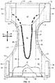
- the disclosure relates to an absorbent core comprising a front portion; a back portion; a middle portion positioned between the front portion and the back portion; and a longitudinal axis extending along a length of said core and crossing said front, middle and back portions, the absorbent core having a width extending perpendicular to said length and a perimeter comprising at least two opposing ends and at least two opposing sides positioned between said ends wherein the absorbent core comprises one or more channels having a first shape when the absorbent core is in dry state and a second shape when the absorbent core is in wet state and wherein said first and second shapes are different.
- the disclosure relates to an absorbent core comprising substantially continuous zones of one or more high fluid distribution structures and discontinuous zones of fluid absorption structures surrounding the one or more high fluid distribution structures, wherein the one or more high fluid distribution structures are arranged to distribute fluid across the absorbent core at a speed that is faster than the speed of fluid distribution across the absorbent core by said discontinuous fluid absorption structures, and wherein said continuous zones extend along a path that is substantially parallel to at least a portion of the perimeter of the core, said portion of the perimeter of the core comprising at least a portion of the sides of the core and one of the ends of the core.
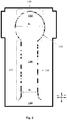
- an absorbent core comprising: a front portion; a back portion; a crotch portion position between the front portion and the back portion; and a longitudinal axis extending along a length of said core and crossing said front, crotch and back portions, the absorbent core having a width extending perpendicular to said length and a perimeter comprising at least two opposing ends and at least two opposing sides positioned between said ends wherein the absorbent core comprises one or more substantially interconnected channels extending through at least a portion of the crotch portion along the length of the core and along at least a portion of said width of the core from one side of the core to the other, preferably said one or more substantially interconnected channels being symmetric or asymmetric about the longitudinal axis.
- the absorbent core has at least one of the interconnected channels, preferably each said channel, forming a shape having a closed end in the form of a U-bend, and preferably an open end in the form of two diverging ends or a funnel-shape, preferably wherein the closed end is positioned proximal to the back portion of the absorbent core and the open end is positioned proximal to the front portion of the absorbent core and distal from said closed end.
- the disclosure relates to an absorbent article comprising said core, preferably said article being selected from disposable diapers or diaper pants; disposable incontinence diapers or diaper pants; sanitary napkins; or panty liners; and typically wherein the channels in said core remain visible both before and after use of the article, preferably wherein the channels are more visible after use than before use of the article.
- the disclosure relates to the use of an absorbent core according to the disclosure in an absorbent article, for improved liquid distribution compared to the same absorbent article comprising a core free of substantially interconnected channels.
- the disclosure relates to the use of an absorbent core according to the disclosure in an absorbent article, for providing a tri-stage fluid distribution comprising a first fluid distribution at a first speed, a second fluid distribution at a second speed and a third fluid distribution at a third speed, said first speed being greater or equal to said second speed and said third speed being less than said first speed and less than or equal to said second speed, preferably wherein the first fluid distribution is driven by the substantially interconnected channels, the second fluid distribution is driven by a three-dimensional absorbent material comprised within the core, and the third fluid distribution is driven by an amount of super absorbent polymer dispersed within the three-dimensional absorbent material.
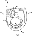
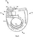
- the disclosure relates to a process of making an absorbent core comprising the steps of: providing a mold comprising a 3D insert therein, said 3D insert being the inverse shape of the desired channels, wherein substantially the entire surface of the mold is in fluid communication with an under-pressure source except for the 3D insert; applying a first nonwoven web to said mold; applying a three-dimensional absorbent material over at least a portion of said nonwoven; applying a second nonwoven web directly or indirectly over the three-dimensional absorbent material; optionally applying a bonding step to form a laminate comprising said first nonwoven, said second nonwoven and said three-dimensional absorbent material therebetween; optionally removing said laminate from the mold to form an absorbent core comprising channels having the inverse shape of said 3D insert; and wherein at least for the duration of the step of applying a three-dimensional absorbent material, the underpressure source is arranged to provide a vacuum force forcing said three-dimensional absorbent material around the 3D insert such to substantially evacuate the surface thereof from three-dimensional absorb
- a compartment refers to one or more than one compartment.
- the value to which the modifier "about” refers is itself also specifically disclosed.
- % by weight refers to the relative weight of the respective component based on the overall weight of the formulation.
- Absorbent article refers to devices that absorb and contain liquid, and more specifically, refers to devices that are placed against or in proximity to the body of the wearer to absorb and contain the various exudates discharged from the body.
- Absorbent articles include but are not limited to diapers, adult incontinence briefs, training pants, diaper holders and liners, sanitary napkins and the like, as well as surgical bandages and sponges.
- Absorbent articles preferably comprise a longitudinal axis and a transversal axis perpendicular to said longitudinal axis.
- Disposable absorbent articles can include a liquid pervious top sheet, a back sheet joined to the top sheet, and an absorbent core positioned and held between the top sheet and the back sheet.
- the top sheet is operatively permeable to the liquids that are intended to be held or stored by the absorbent article, and the back sheet may or may not be substantially impervious or otherwise operatively impermeable to the intended liquids.
- the absorbent article may also include other components, such as liquid wicking layers, liquid intake layers, liquid distribution layers, transfer layers, barrier layers, wrapping layers and the like, as well as combinations thereof. Disposable absorbent articles and the components thereof can operate to provide a body-facing surface and a garment-facing surface.
- An absorbent article such as a diaper, comprises a front waistband region, a back waistband region, an intermediate crotch region which interconnects the front and rear waistband regions.
- a front portion refers to that part of the absorbent article which is generally located on the front of a subject, such as an infant or adult, when in use.
- Reference to the "rear” portion refers to the portion of the absorbent article generally located at the rear of the subject, such as an infant or adult, when in use
- reference to the "crotch” portion refers to that portion which is generally located between the legs of subject, such as an infant or adult, when in use.
- the crotch region is an area where repeated fluid surge typically occurs, within the absorbent article assembly.
- Front, “rear or back”, and “crotch” portions of the absorbent core as used herein typically refer to portions of the absorbent core that are proximal to respective portions of the absorbent article.
- the "front” portion of the core is that which is most proximal to the front of the subject when worn
- the "rear or back” portion of the core is that which is most proximal to the rear or back of the subject when worn
- the "crotch” portion of the core is the middle portion of the absorbent core between the "front” and “rear or back” portions.
- a diaper comprises a liquid permeable "top sheet”, a liquid impermeable “back sheet”, and an "absorbent medium” disposed between the top sheet and the back sheet.
- the top sheet, back sheet and the absorbent medium could be made from any suitable material known to the person skilled in the art.
- the top sheet is generally located at or near the bodyside surface of the article, while the back sheet is generally located at or near the garment-side surface of the article.
- the article may comprise one or more separate layers which are in addition to the back sheet and are interposed between the back sheet and the absorbent medium. Top sheet and back sheet are connected or otherwise associated together in an operable manner.
- the "absorbent medium” or “absorbent core” or “absorbent body” is the absorbent structure disposed between the top sheet and the back sheet of the absorbent article in at least the crotch region of the absorbent article and is capable of absorbing and retaining liquid body exudates.
- the size and the absorbent capacity of the absorbent medium should be compatible with the size of the intended wearer and the liquid loading imparted by the intended use of the absorbent article. Further, the size and the absorbent capacity of the absorbent medium can be varied to accommodate wearers ranging from infants through adults. It may be manufactured in a wide variety of shapes (for example, rectangular, trapezoidal, T-shape, I-shape, hourglass shape, etc.) and from a wide variety of materials.
- absorbent materials are cellulosic fluff pulp, tissue layers, highly absorbent polymers (so called superabsorbent polymer particles (SAP)), absorbent foam materials, absorbent nonwoven materials or the like. It is common to combine cellulosic fluff pulp with superabsorbent polymers in an absorbent material.
- SAP superabsorbent polymer particles
- Acquisition and distribution layer refers to a sublayer which preferably is a nonwoven wicking layer under the top sheet of an absorbent product, which speeds up the transport and improves distribution of fluids throughout the absorbent core.
- the surge management portion is typically less hydrophilic than the retention portion, and has the ability to quickly collect and temporarily hold liquid surges, and to transport the liquid from its initial entrance point to other parts of the absorbent structure, particularly the retention portion. This configuration can help prevent the liquid from pooling and collecting on the portion of the absorbent garment positioned against the wearer's skin, thereby reducing the feeling of wetness by the wearer.
- the surge management portion is positioned between the top sheet and the retention portion.
- the term "bulk density” as used herein refers to the weight of a material per unit of volume. Bulk density is generally expressed in units of weight/volume (e.g., grams per cubic centimeter).
- the bulk density of flat, generally planar materials such as, for example, fibrous nonwoven webs, may be derived from measurements of thickness and basis weight of a sample. The thickness of the samples is determined utilizing a Model 49-70 thickness tester available from TMI (Testing Machines Incorporated) of Amityville, New York (alternatively, a portable thickness gauge J 100/A may be used). The thickness is measured using a 6.45 cm (2-inch) diameter circular foot at an applied pressure of about 1.38 ⁇ 10 3 Pa (about 0.2 pounds per square inch (psi)).
- the basis weight of the sample is determined essentially in accordance with ASTM D-3776-9 with the following changes: 1) sample size is cut to 10.16 cm X 10.16 cm (4 inches X 4 inches) square and 2); a total of 9 samples are weighed.
- volume refers to the inverse bulk density of material being measured in volume per a unit weight and may be expressed in units of cubic centimeters per gram.
- mean flow pore size refers to a measure of average pore diameter as determined by a liquid displacement techniques utilizing a Coulter Porometer and Coulter POROFIL® test liquid available from Coulter Electronics Limited, Luton, England.
- the mean flow pore size is determined by wetting a test sample with a liquid having a very low surface tension (i.e., Coulter POROFIL®). Air pressure is applied to one side of the sample. Eventually, as the air pressure is increased, the capillary attraction of the fluid in the largest pores is overcome, forcing the liquid out and allowing air to pass through the sample. With further increases in the air pressure, progressively smaller and smaller holes will clear.
- a flow versus pressure relationship for the wet sample can be established and compared to the results for the dry sample.
- the mean flow pore size is measured at the point where the curve representing 50% of the dry sample flow versus pressure intersects the curve representing wet sample flow versus pressure.
- the diameter of the pore which opens at that particular pressure i.e., the mean flow pore size
- adhesive as used herein is intended to refer to any suitable hot melt, water or solvent borne adhesive that can be applied to a surface of a film layer in the required pattern or network of adhesive areas to form the film-nonwoven laminate of the present disclosure.
- suitable adhesives include conventional hot melt adhesives, pressure-sensitive adhesives and reactive adhesives (i.e., polyurethane).
- adhesive bonding means a bonding process which forms a bond by application of an adhesive.
- adhesive may be by various processes such as slot coating, spray coating and other topical applications. Further, such adhesive may be applied within a product component and then exposed to pressure such that contact of a second product component with the adhesive containing product component forms an adhesive bond between the two components.
- an "airformed web” refers to a material comprising cellulosic fibers such as those from fluff pulp that have been separated, such as by a hammermilling process, and then deposited on a porous surface without a substantial quantity of binder fibers present.
- Airfelt materials used as the absorbent core in many diapers, for example, are a typical example of an airformed material.
- an "airlaid web” is a fibrous structure formed primarily by a process involving deposition of air-entrained fibers onto a mat, typically with binder fibers present, and typically followed by densification and thermal bonding.
- airlaid can also include coform, which is produced by combining air-entrained dry, dispersed cellulosic fibers with meltblown synthetic polymer fibers while the polymer fibers are still tacky.
- coform which is produced by combining air-entrained dry, dispersed cellulosic fibers with meltblown synthetic polymer fibers while the polymer fibers are still tacky.
- an airformed web to which binder material is subsequently added can be considered within the scope of the term "airlaid” according to the present disclosure.
- Binder can be added to an airformed web in liquid form (e. g., an aqueous solution or a melt) by spray nozzles, direction injection or impregnation, vacuum drawing, foam impregnation, and so forth. Solid binder particles can also be added by mechanical or pneumatic means.
- liquid form e. g., an aqueous solution or a melt
- Solid binder particles can also be added by mechanical or pneumatic means.
- an "air-through-bonded" nonwoven is a nonwoven structure primarily formed by a process that comprises the application of heated air to the surface of the nonwoven fabric.
- heated air flows through holes in a plenum above the nonwoven material.
- the through air process uses negative pressure of suction to pull the air through an open conveyor apron holding nonwoven as it is drawn through the oven. Pulling air through the material allows the rapid and even transmission of heat to minimize distortion of the nonwoven material.
- the binding agents used in the through air bonding process include crystalline binder fibers and powders, which melt to form molten droplets throughout the cross-section of the nonwoven. As the material is cooled, bonding occurs at these droplet points.
- top sheet and back sheet can be affixed directly to each other by attachment means such as an adhesive, sonic bonds, thermal bonds or any other attachment means known in the art.
- attachment means such as an adhesive, sonic bonds, thermal bonds or any other attachment means known in the art.
- a uniform continuous layer of adhesive, a patterned layer of adhesive, a sprayed pattern of adhesive or an array of separate lines, swirls or spots of construction adhesive may be used to affix top sheet to back sheet.
- attachment means may also be employed to interconnect and assemble together the various other component parts of the article described herein.
- back section and “rear back section” are used herein as synonyms and refer to the area of the absorbent article which is contact with the back of the wearer when the absorbent article is worn.
- back sheet refers to a material forming the outer cover of the absorbent article.
- the back sheet prevents the exudates contained in the absorbent structure from wetting articles such as bedsheets and overgarments which contact the disposable absorbent article.
- the back sheet may be a unitary layer of material or may be a composite layer composed of multiple components assembled side-by-side or laminated.
- the back sheet may be the same or different in different parts of the absorbent article.
- the back sheet comprises a liquid impervious material in the form of a thin plastic film, e.g.
- a polyethylene or polypropylene film a nonwoven material coated with a liquid impervious material, a hydrophobic nonwoven material, which resists liquid penetration, or a laminate of a plastic film and a nonwoven material.
- the back sheet material may be breathable so as to allow vapour to escape from the absorbent material, while still preventing liquids from passing there through. Examples of breathable back sheet materials are porous polymeric films, nonwoven laminates of spunbond and meltblown layers and laminates of porous polymeric films and nonwoven materials.
- belly section and "front belly section” are used herein as synonyms and refer to the area of the absorbent article which is contact with the belly of the wearer when the absorbent article is worn.
- blend means a mixture of two or more polymers while the term “alloy” means a sub-class of blends wherein the components are immiscible but have been compatibilized.
- the "skin-facing", “body-facing” or “bodyside” surface means that surface of the article or component which is intended to be disposed toward or placed adjacent to the body of the wearer during ordinary use, while the "outward”, “outward-facing” or “garment-side” surface is on the opposite side, and is intended to be disposed to face away from the wearer's body during ordinary use.
- Such outward surface may be arranged to face toward or placed adjacent to the wearer's undergarments when the absorbent article is worn.
- Binded refers to the joining, adhering, connecting, attaching, or the like, of at least two elements. Two elements will be considered to be bonded together when they are bonded directly to one another or indirectly to one another, such as when each is directly bonded to intermediate elements.
- breathable refers to films having a water vapor transmission rate (WVTR) of at least 300 grams/m 2 - 24 hours.
- Carded web (or layer(s) or nonwoven) refers to webs that are made from staple fibers that are sent through a combing or carding unit, which opens and aligns the staple fibers in the machine direction to form a generally machine direction-oriented fibrous nonwoven web. The web is then bonded by one or more of several known bonding methods.
- Bonding of nonwoven webs may be achieved by a number of methods; powder bonding, wherein a powdered adhesive or a binder is distributed through the web and then activated, usually by heating the web and adhesive with hot air; pattern bonding, wherein heated calendar rolls or ultrasonic bonding equipment are used to bond the fibers together, usually in a localized bond pattern, though the web can be bonded across its entire surface if so desired; through-air bonding, wherein air which is sufficiently hot to soften at least one component of the web is directed through the web; chemical bonding using, for example, latex adhesives that are deposited onto the web by, for example, spraying; and consolidation by mechanical methods such as needling and hydroentanglement.
- Carded thermobonded nonwoven thus refers to a carded nonwoven wherein the bonding is achieved by use of heat.
- the term "cellulosic” is meant to include any material having cellulose as a major constituent, and specifically comprising at least 50 percent by weight cellulose or a cellulose derivative.
- the term includes cotton, typical wood pulps, nonwoody cellulosic fibers, cellulose acetate, cellulose triacetate, rayon, thermomechanical wood pulp, chemical wood pulp, debonded chemical wood pulp, milkweed, or bacterial cellulose.
- Chassis refers to a foundational constituent of an absorbent article upon which the remainder of the structure of the article is built up or overlaid, e.g., in a diaper, the structural elements that give the diaper the form of briefs or pants when configured for wearing, such as a back sheet, a top sheet, or a combination of a top sheet and a back sheet.
- Coform as used herein is intended to describe a blend of meltblown fibers and cellulose fibers that is formed by air forming a meltblown polymer material while simultaneously blowing air-suspended cellulose fibers into the stream of meltblown fibers.
- the coform material may also include other materials, such as superabsorbent particles.
- the meltblown fibers containing wood fibers are collected on a forming surface, such as provided by a foraminous belt.
- the forming surface may include a gas-pervious material, such as spunbonded fabric material, that has been placed onto the forming surface.
- “Compression” refers to the process or result of pressing by applying force on an object, thereby increasing the density of the object.
- compositions consisting essentially of
- materials that do not significantly affect the desired characteristics of a given composition or product.
- Exemplary materials of this sort would include, without limitation, pigments, antioxidants, stabilizers, surfactants, waxes, flow promoters, solvents, particulates and materials added to enhance processability of the composition.
- the diaper can comprise "containment flaps" or “barrier cuffs".
- the containment flaps are generally thought to be particularly well suited for the containment of fecal matter and to prevent the lateral flow of liquid waste until such time as the liquid waste can be absorbed by the absorbent article.
- Many constructions of containment flaps are known.
- Such containment flaps generally comprise a proximal edge, intended to be attached to the absorbent article, and an opposite distal edge which is generally not attached to the absorbent article along at least a portion of its length.
- An elastic member is generally located adjacent the distal edge to assist in maintaining the containment flap in an upright condition and in maintaining a sealing relationship between the distal edge of the containment flap and the body of a wearer during use.
- the elastic member is generally located between two layers of material so that the elastic does not come into contact with the body of a wearer.
- the containment flaps may be manufactured from a wide variety of materials such as polypropylene, polyester, rayon, nylon, foams, plastic films, formed films, and elastic foams. A number of manufacturing techniques may be used to manufacture the containment flaps. For example, the containment flaps may be woven, non-woven, spunbonded, carded, cast, blown or the like.
- the diaper can comprise leg containment gaskets.
- Leg "containment gaskets" help prevent leakage of bodily exudates when the wearer exerts compressive forces on the absorbent article.
- the stiffness of the leg containment gaskets prevents twisting and bunching of the leg openings of the absorbent article which can lead to leaks.
- the elasticity and conformability of the leg containment gaskets ensures that the bodyfacing surface of the leg containment gaskets provides an adequate seal against the body of the wearer.
- the physical properties of the leg containment gaskets, such as the thickness and stiffness also function to space the bodyside liner, outer cover and absorbent core away from the wearer's body when in use. As such, void volume is created between the wearer's body and the bodyside liner and absorbent core of the absorbent article to help contain body exudates.
- a “continuous waistband” can be an elastomeric, cloth-like, nonwoven fibrous material, such as an elastomeric stretch bonded laminate web or an elastomeric meltblown web.
- the continuous waistband can be rendered temporarily elastically inhibited, such as by compression.
- the elastic material, of which waistband is comprised can be activated, such as by treating with heat, to recover to a state of elasticity.
- Conventional hot-melt adhesive means a formulation that generally comprises several components. These components typically include one or more polymers to provide cohesive strength (e.g., aliphatic polyolefins such as poly (ethylene-co-propylene) copolymer; ethylene vinyl acetate copolymers; styrene-butadiene or styrene- isoprene block copolymers; etc.); a resin or analogous material (sometimes called a tackifier) to provide adhesive strength (e.g., hydrocarbons distilled from petroleum distillates; rosins and/or rosin esters; terpenes derived, for example, from wood or citrus, etc.); perhaps waxes, plasticizers or other materials to modify viscosity (i.e., flowability) (examples of such materials include, but are not limited to, mineral oil, polybutene, paraffin oils, ester oils, and the like); and/or other additives including, but not limited to, antioxidant
- a typical hot-melt adhesive formulation might contain from about 15 to about 35 weight percent cohesive strength polymer or polymers; from about 50 to about 65 weight percent resin or other tackifier or tackifiers; from more than zero to about 30 weight percent plasticizer or other viscosity modifier; and optionally less than about 1 weight percent stabilizer or other additive. It should be understood that other adhesive formulations comprising different weight percentages of these components are possible.
- density or “concentration” when referring to the absorbent material, in particular the SAP, of a layer, refers to the amount of the absorbent material divided by the surface area of the layer over which the absorbent material is spread out.
- the term "diaper” refers to an absorbent article generally worn by infants about the lower torso.
- absorbent articles that generally are not intended to be laundered or otherwise restored or reused as an absorbent article (i.e., they are intended to be discarded after a single use and, preferably, to be recycled, composted or otherwise disposed of in an environmentally compatible manner).
- the term "elastic resistance” describes an elastic force that tends to resist an applied tensile force causing a material provided therewith to tend to contract to an untensioned configuration in response to a stretching force.
- the terms "elastic”, “elastomeric”, “elasticity” or derivations thereof are used to describe the ability of various materials and objects comprised of such to reversibly undergo deformation under stress, e.g., become stretched or extended, in at least one direction when a force is applied to the material and to resume substantially to their original dimensions upon relaxing, i.e., when the force is released, without rupture or breakage.
- it refers to a material or composite which can be elongated in at least one direction by at least 50% of its relaxed length, i.e., elongated to at least 150% of its relaxed length, and which will recover upon release of the applied tension at least 40% of its elongation.
- elastomer materials include polyether-polyamide block copolymers, polyurethanes, synthetic linear A-B-A and A-B block copolymers, chlorinated rubber/EVA (ethylene-vinyl acetate) blends, EPDM (ethylene-propylene diene monomer) rubbers, EPM (ethylene-propylene monomer) rubbers, blends of EPDM/EPM/EVA, and the like.
- elasticized refers to a material, layer, or substrate that is naturally non-elastic, but which has been rendered elastic by, for example, suitably joining an elastic material, layer, or substrate thereto.
- Extension means the ratio of the extension of a material to the length of the material prior to the extension (expressed in percent), as represented by the following: “Extension” means the change in length of a material due to stretching (expressed in units of length).
- fabrics is used to refer to all of the woven, knitted and nonwoven fibrous webs.
- Fastening means such as tape tab fasteners
- Tapening means are typically applied to the back waistband region of the diaper to provide a mechanism for holding the diaper on the wearer.
- Fastening means such as tape tab fasteners, snaps, pins, belts, hooks, buckles, "hook/mushroom”-and-loop fasteners (e.g. VELCRO®-type fasteners) and the like, may be employed and are typically applied at the lateral, side ends of the back waistband region of diaper to provide a mechanism for holding the diaper about the waist of the wearer in a conventional manner.
- Tape tab fasteners can be any of those well known in the art, and are typically applied to the corners of the diaper.
- adhesive fasteners may be used alone, or in combination.
- the fasteners can be adhesive fasteners, which are constructed to releasably adhere to a landing zone patch attached to the front waistband section of the diaper to provide a refastenable adhesive fastening system.
- finished or “final”, when used with reference to a product, means that the product has been suitably manufactured for its intended purpose.
- the term "garment” means any type of apparel which may be worn. This includes diapers, training pants, incontinence products, surgical gowns, industrial workwear and coveralls, undergarments, pants, shirts, jackets and the like.
- Gel blocking occurs when superabsorbent polymer particles are wetted and the particles swell so as to inhibit fluid transmission to other regions of the absorbent structure. Wetting of these other regions of the absorbent member therefore takes place via a very slow diffusion process. In practical terms, this means acquisition of fluids by the absorbent structure is much slower than the rate at which fluids are discharged, especially in gush situations. Leakage from the absorbent article can take place well before the particles of SAP in the absorbent member are even close to being fully saturated or before the fluid can diffuse or wick past the "blocking" particles into the rest of the absorbent member. Gel blocking can be a particularly acute problem if the superabsorbent polymer particles do not have adequate gel strength and deform or spread under stress once the particles swell with absorbed fluid.
- graphics includes, but is not limited to, any type of design, image, mark, figure, codes, words, patterns, or the like.
- graphics will generally include objects associated with little boys and little girls, such as multi-color trucks, airplanes, balls, dolls, bows, or the like.
- Hydroentanglement process refers to the manufacturing of nonwoven webs. The process involves directing a series of water jets towards a fibrous web which is supported on a moving porous belt. The water jets pass downwards through the mass of fibres and on making contact with the surface of the belt, the jets rebound, and break up: the energy released causes entanglement of the mass of fibres.
- high-absorbency material refers to materials that are capable of absorbing at least 10 times their own weight in liquid.
- the high-absorbency material may comprise absorbent gelling materials, such as superabsorbent polymers.
- Superabsorbent polymers are water-swellable, water-insoluble organic or inorganic materials capable of absorbing at least about 20 times their own weight of an aqueous solution containing 0.9 weight percent of sodium chloride.
- Absorbent gelling materials can be natural, synthetic and modified natural polymers and materials.
- the absorbent gelling materials can be inorganic materials, such as silica gels, or organic compounds such as cross-linked polymers.
- cross-linked refers to any means for effectively rendering normally water-soluble materials substantially water insoluble but swellable. Such means can include, for example, physical entanglement, crystalline domains, covalent bonds, ionic complexes and associations, hydrophilic associations, such as hydrogen bonding, and hydrophobic associations or Van der Waals forces.
- Examples of synthetic absorbent gelling material polymers include the alkali metal and ammonium salts of poly(acrylic acid) and poly (methacrylic acid), poly(acrylamides), poly(vinyl ethers), maleic anhydride copolymers with vinyl ethers and alpha-olefins, poly(vinyl pyrrolidone), poly(vinylmorpholinone), poly(vinyl alcohol), and mixtures and copolymers thereof.
- Further polymers suitable for use in the absorbent structure include natural and modified natural polymers, such as hydrolyzed acrylonitrile-grafted starch, acrylic acid grafted starch, methyl cellulose, carboxymethyl cellulose, hydroxypropyl cellulose, and the natural gums, such as alginates, xanthan gum, locust bean gum and the like. Mixtures of natural and wholly or partially synthetic absorbent polymers can also be used.
- Synthetic absorbent gelling materials typically are xerogels which form hydrogels when wetted. The term "hydrogel", however, has commonly been used to also refer to both the wetted and unwetted forms of the material.
- the high-absorbency material may be in any of a wide variety of geometric forms.
- the high-absorbency material be in the form of discrete particles.
- the high-absorbency material may also be in the form of fibres, flakes, rods, spheres, needles, spiral or semi-spiral, cubic, rod-like, polyhedral, or the like. Conglomerates of particles of high-absorbency material may also be used.
- the high-absorbency material may be present in the absorbent core in an amount of from about 5 to about 100 weight percent and desirably from about 30 to about 100 weight percent based on the total weight of the absorbent core. The distribution of the high-absorbency material within the different portions of the absorbent core can vary depending upon the intended end use of the absorbent core.
- the high-absorbency material may be arranged in a generally discrete layer within the matrix of hydrophilic fibres.
- the absorbent core may comprise a laminate of fibrous webs and high-absorbency material or other suitable means of maintaining a high-absorbency material in a localized area.
- a “hook-and-loop fastener” refers to complementary fastening means having a “hook” portion and a “loop” portion and which are refastenable.
- the term “hook” as used herein refers to any element capable of engaging another element, the so called “loop” portion.
- the term “hook” is not limited to only “hooks” in its normal sense, but rather encompasses any form of engaging elements, whether unidirectional or bi-directional.
- the term “loop” is likewise not limited to “loops” in its normal sense, but also encompasses any structure capable of engaging with a "hook” fastener. Examples of “loop” materials are fibrous structures, like nonwoven materials.
- hydrophilic describes fibers or the surfaces of fibers which are wetted by the aqueous liquids in contact with the fibers.
- the degree of wetting of the materials can, in turn, be described in terms of the contact angles and the surface tensions of the liquids and materials involved.
- wettable is meant to refer to a fiber which exhibits a liquid, such as water, synthetic urine, or a 0.9 weight percent aqueous saline solution, in air contact angle of less than 90°, whereas “hydrophobic” or “non-wettable” describes fibers having contact angles equal to or greater than 90°.
- the term "impermeable” generally refers to articles and/or elements that are substantially not penetrated by aqueous fluid through the entire thickness thereof under a pressure of 1.0 kPa or less.
- the impermeable article or element is not penetrated by aqueous fluid under pressures of 3.4 kPa or less. More preferably, the impermeable article or element is not penetrated by fluid under pressures of 6.8 kPa or less.
- An article or element that is not impermeable is permeable.
- Integral is used to refer to various portions of a single unitary element rather than separate structures bonded to or placed with or placed near one another.
- Join when used in describing the relationship between two or more elements, means that the elements can be connected together in any suitable manner, such as by heat sealing, ultrasonic bonding, thermal bonding, by adhesives, stitching, or the like. Further, the elements can be joined directly together, or may have one or more elements interposed between them, all of which are connected together.
- said-flat state is intended to refer to the article when it is flattened into a plane or is substantially flattened into a plane and is used in contrast to when the article otherwise positioned, such as when the article is folded or shaped in or for use by a wearer.
- Laminate refers to elements being attached together in a layered arrangement.
- a layer can refer, but is not limited, to any type of substrate, such as a woven web, nonwoven web, films, laminates, composites, elastomeric materials, or the like.
- a layer can be liquid and air permeable, permeable to air but impermeable to liquids, impermeable both to air and liquid, or the like. When used in the singular, it can have the dual meaning of a single element or a plurality of elements.
- the crotch portion of the absorbent article preferably comprises opposite longitudinal side portions which comprise a pair of elasticized, longitudinally-extending "leg cuffs".
- the leg cuffs are generally adapted to fit about the legs of a wearer when in use and serve as a mechanical barrier to the lateral flow of body exudates.
- Leg cuffs are elasticized by leg elastics.
- the diaper further can comprise a front waist elastic and a rear waist elastic.
- leg elastics Materials suitable for use in forming leg elastics are known to those skilled in the art. Exemplary of such materials are strands or ribbons of a polymeric, elastomeric material which are adhered to the diaper at the leg cuff while in a stretched position, or which are attached to the diaper while the diaper is pleated, such that elastic constrictive forces are imparted to the leg cuff.
- elastomer materials examples include polyether-polyamide block copolymers, polyurethanes, synthetic linear A-B-A and A-B block copolymers, chlorinated rubber/EVA (ethylene-vinyl acetate) blends, EPDM (ethylene-propylene diene monomer) rubbers, EPM (ethylene-propylene monomer) rubbers, blends of EPDM/EPM/EVA, and the like.
- polyether-polyamide block copolymers examples include polyurethanes, synthetic linear A-B-A and A-B block copolymers, chlorinated rubber/EVA (ethylene-vinyl acetate) blends, EPDM (ethylene-propylene diene monomer) rubbers, EPM (ethylene-propylene monomer) rubbers, blends of EPDM/EPM/EVA, and the like.
- EPDM ethylene-propylene diene monomer
- EPM ethylene-propylene monomer
- Liquid means a nongaseous substance and/or material that flows and can assume the interior shape of a container into which it is poured or placed.
- Longitudinal is a direction running parallel to the maximum linear dimension of the article.
- meltblown fibers means fibers formed by extruding a molten thermoplastic material through a plurality of fine, usually circular, die capillaries as molten threads or filaments into a high velocity gas stream (e.g. air) which attenuates the filaments of molten thermoplastic material to reduce their diameter, which may be to microfiber diameter.
- a high velocity gas stream e.g. air
- meltblown fibers have an average fiber diameter of up to about 10 microns. After the fibers are formed, the meltblown fibers are carried by the high velocity gas stream and are deposited on a collecting surface to form a web of randomly disbursed meltblown fibers.
- nonwoven fabric or web means a sheet material having a structure of individual fibers or threads which are interlaid, but not in a regular manner such as occurs with knitting or weaving processes.
- Nonwoven fabrics or webs have been formed from many processes such as for example, meltblowing processes, spunbonding processes, and bonded carded web processes.
- Pant body refers to a garment that has a waist opening and a pair of leg openings, similar to shorts, swim wear, or the like.
- the described garment may or may not have a manually tearable side seam.
- the material is generally in the form of discrete units.
- the units can comprise granules, powders, spheres, pulverized materials or the like, as well as combinations thereof.
- the particles can have any desired shape such as, for example, cubic, rod-like, polyhedral, spherical or semi-spherical, rounded or semi-rounded, angular, irregular, etc. Shapes having a large greatest dimension/smallest dimension ratio, like needles, flakes and fibers, are also contemplated for inclusion herein.
- particle or “particulate” may also include an agglomeration comprising more than one individual particle, particulate or the like. Additionally, a particle, particulate or any desired agglomeration thereof may be composed of more than one type of material.
- polymer generally includes, but is not limited to, homopolymers, copolymers, such as, for example, block, graft, random and alternating copolymers, terpolymers, etc. and blends and modifications thereof. Furthermore, unless otherwise specifically limited, the term “polymer” shall include all possible geometrical configurations of the material. These configurations include, but are not limited to, isotactic, syndiotactic and random symmetries.
- pre-packed is meant that one or more absorbent articles are packed in a single unit before being stacked.
- Pulp fluff or "fluff pulp” refers to a material made up of cellulose fibers.
- the fibers can be either natural or synthetic, or a combination thereof.
- the material is typically lightweight and has absorbent properties.
- Refastenable refers to the property of two elements being capable of releasable attachment, separation, and subsequent releasable reattachment without substantial permanent deformation or rupture.
- the "retention portion” or “liquid absorption layer” is part of the absorbent medium.
- This portion may comprise a matrix of hydrophilic fibers, such as a web of cellulosic fluff, mixed with particles of high-absorbency material.
- the retention portion may comprise a mixture of superabsorbent hydrogel-forming particles and synthetic polymer meltblown fibers, or a mixture of superabsorbent particles with a fibrous coform material comprising a blend of natural fibers and/or synthetic polymer fibers.
- the superabsorbent particles may be substantially homogeneously mixed with the hydrophilic fibers, or may be nonuniformly mixed.
- the concentrations of superabsorbent particles may be arranged in a non-step-wise gradient through a substantial portion of the thickness of the absorbent structure, with lower concentrations toward the bodyside of the absorbent structure and relatively higher concentrations toward the outerside of the absorbent structure.
- the superabsorbent particles may also be arranged in a generally discrete layer within the matrix of hydrophilic fibers.
- two or more different types of superabsorbent may be selectively positioned at different locations within or along the fiber matrix.
- sheet or “sheet material” refers to woven materials, nonwoven webs, polymeric films, polymeric scrim-like materials, and polymeric foam sheeting.
- the absorbent article may also contain side panels.
- the "side panels” can have any shape such as but not limited to square, rectangular, triangular, circular and trapezoidal shape. They can be joined to the respective opposite side portions of the back section, by a known method, such as heat-sealing or adhesive bonding.
- the side panels may also be formed integrally with the back section by projecting and joining together the respective top sheet and/or back sheet and/or absorbent medium outward in lugs having the shape of the side panels.
- the side panels are formed by laminating a layer of nonwoven fabric, a layer of thermoplastic film and a layer of elastic material.
- the layer of elastic material might be sandwiched between the nonwoven fabric layer and the thermoplastic film by adhesive layers.
- the layer of nonwoven fabric might be made of natural fibers, synthetic fibers or a blend of natural fibers and synthetic fibers.
- the layer of thermoplastic film might be made of polyethylene or polypropylene.
- spunbond fibers or layer(s) or nonwovens
- spunbond fibers refers to fibers formed by extruding molten thermoplastic polymers as filaments or fibers from a plurality of relatively fine, usually circular, capillaries of a spinneret, and then rapidly drawing the extruded filaments by an eductive or other well-known drawing mechanism to impart molecular orientation and physical strength to the filaments.
- the average diameter of spunbond fibers is typically in the range of from 15-60 ⁇ m or higher.
- the spinneret can either be a large spinneret having several thousand holes per meter of width or be banks of smaller spinnerets, for example, containing as few as 40 holes.
- SMS nonwoven fabric refers to a multi-layer composite sheet comprising a web of meltblown fibers sandwiched between and bonded to two spunbond layers.
- a SMS nonwoven fabric can be formed in-line by sequentially depositing a first layer of spunbond fibers, a layer of meltblown fibers, and a second layer of spunbond fibers on a moving porous collecting surface. The assembled layers can be bonded by passing them through a nip formed between two rolls that can be heated or unheated and smooth or patterned. Alternately, the individual spunbond and meltblown layers can be pre-formed and optionally bonded and collected individually such as by winding the fabrics on wind-up rolls.
- the individual layers can be assembled by layering at a later time and bonded together to form a SMS nonwoven fabric. Additional spunbond and/or meltblown layers can be incorporated in the SMS fabric, for example spunbond-meltblown-meltblown-spunbond (SMMS), etc.
- SMSMS spunbond-meltblown-meltblown-spunbond
- “Staple fibers” refer to commercially available fibers having diameters ranging from less than about 0.001 mm to more than about 0.2 mm; they come in several different forms such as short fibers ranging from about 10 to 50 mm in length and long fibers with a length higher than 50 mm, preferably up to 100 mm.
- stretch it is meant that the material has the ability to extend beyond its original size in at least one dimension when subjected to a tensile force (i. e., tension) applied in the direction of that dimension, without breaking the material.
- An extension of for example 50% means that the material with an initial length of 100mm has reached a length of 150mm.
- Stretch may be unidirectional, bi-directional, or multi-directional.
- the specific stretch properties of a material may vary along any of the stretch vectors.
- the term can include elastic materials, as well as nonwovens that can be inherently extensible, but not necessarily in an elastic manner. Such nonwovens can be made to behave in an elastic manner by bonding them to elastic films.
- channels it is meant that the structure referred to (e.g. the absorbent core) comprises recessed regions forming visible conduits or passages typically extending along the longitudinal axis of the core and having a depth in a direction perpendicular to said longitudinal axis.
- visible it is herein intended clearly visible by naked eye and typically that the channels have a width generally greater than 1mm, preferably from 5mm to 50mm, more preferably from 8mm to 40mm, more preferably from 10mm to 30mm, even more preferably from greater than 10mm to less than 25mm.
- interconnected it is meant that the structure referred to (e.g. the channels) from a substantially continuous path such as from a first end of a channel to a second end of the same channel.
- substantially interconnected means that the majority of the channel is interconnected and generally wherein a direct and continuous path can be traced by starting from one end of the channel towards another end of the channel, said ends (also referred to herein as terminal positions) being distal to each other in a width direction of the core and proximal to a portion of the perimeter of the core, preferably the sides thereof.
- a nonwoven web applied indirectly over a three-dimensional absorbent material comprises a further layer of material between said nonwoven web and said three-dimensional absorbent material.
- substrate includes, but is not limited to, woven or nonwoven webs, porous films, ink permeable films, paper, composite structures, or the like.
- Superabsorbent materials suitable for use in the present disclosure are known to those skilled in the art, and may be in any operative form, such as particulate form, fibers and mixtures thereof.
- the "superabsorbent material” can be a water-swellable, generally water-insoluble, hydrogel-forming polymeric absorbent material, which is capable of absorbing at least about 15, suitably about 30, and possibly about 60 times or more its weight in physiological saline (e.g. saline with 0.9 wt % NaCI).
- the superabsorbent material may be biodegradable or bipolar.
- the hydrogel-forming polymeric absorbent material may be formed from organic hydrogel-forming polymeric material, which may include natural material such as agar, pectin, and guar gum; modified natural materials such as carboxymethyl cellulose, carboxyethyl cellulose, and hydroxypropyl cellulose; and synthetic hydrogel-forming polymers.
- Synthetic hydrogel-forming polymers include, for example, alkali metal salts of polyacrylic acid, polyacrylamides, polyvinyl alcohol, ethylene maleic anhydride copolymers, polyvinyl ethers, polyvinyl morpholinone, polymers and copolymers of vinyl sulfonic acid, polyacrylates, polyacrylamides, polyvinyl pyridine, and the like.
- hydrogel-forming polymers include hydrolyzed acrylonitrile grafted starch, acrylic acid grafted starch, and isobutylene maleic anhydride copolymers and mixtures thereof.
- the hydrogel-forming polymers may be lightly crosslinked to render the material substantially water insoluble. Crosslinking may, for example, be by irradiation or covalent, ionic, Van der Waals, or hydrogen bonding.
- the superabsorbent material may suitably be included in an appointed storage or retention portion of the absorbent system, and may optionally be employed in other components or portions of the absorbent article.
- the superabsorbent material may be included in the absorbent layer or other fluid storage layer of the absorbent article of the present disclosure in an amount up to about 60% by weight. Typically, the superabsorbent material, when present, will be included in an amount of about 5% to about 40% by weight, based on the total weight of the absorbent layer.
- Superabsorbent polymer particles or “SAPs” refer to water-swellable, water-insoluble organic or inorganic materials capable, under the most favorable conditions, of absorbing at least about 10 times their weight, or at least about 15 times their weight, or at least about 25 times their weight in an aqueous solution containing 0.9 weight percent sodium chloride.
- the particle size is typically ranging between 100 to 800 ⁇ m, preferably between 300 to 600 ⁇ m, more preferably between 400 to 500 ⁇ m.
- target zone refers to an area of an absorbent core where it is particularly desirable for the majority of a fluid insult, such as urine, menses, or bowel movement, to initially contact.
- a fluid insult such as urine, menses, or bowel movement
- the insult target zone refers to the area of the absorbent core extending a distance equal to 15% of the total length of the composite from each insult point in both directions.
- Treatment includes a uniaxial force tending to cause the extension of a body or the balancing force within that body resisting the extension.
- thermoplastic is meant to describe a material that softens when exposed to heat and which substantially returns to its original condition when cooled to room temperature.
- top sheet refers to a liquid permeable material sheet forming the inner cover of the absorbent article and which in use is placed in direct contact with the skin of the wearer.
- the top sheet is typically employed to help isolate the wearer's skin from liquids held in the absorbent structure.
- the top sheet can comprise a nonwoven material, e.g. spunbond, meltblown, carded, hydroentangled, wetlaid etc.
- Suitable nonwoven materials can be composed of man-made fibres, such as polyester, polyethylene, polypropylene, viscose, rayon etc. or natural fibers, such as wood pulp or cotton fibres, or from a mixture of natural and man-made fibres.
- the top sheet material may further be composed of two fibres, which may be bonded to each other in a bonding pattern. Further examples of top sheet materials are porous foams, apertured plastic films, laminates of nonwoven materials and apertured plastic films etc. The materials suited as top sheet materials should be soft and non-irritating to the skin and be readily penetrated by body fluid, e.g. urine or menstrual fluid.
- the inner coversheet may further be different in different parts of the absorbent article.
- the top sheet fabrics may be composed of a substantially hydrophobic material, and the hydrophobic material may optionally be treated with a surfactant or otherwise processed to impart a desired level of wettability and hydrophilicity.
- Training pants are available for use by children in the potty-training stage, and are popular with mothers and caretakers.
- a training pant typically comprises a top sheet, a back sheet, an absorbent medium between the top sheet and the back sheet, and side seams that bond portions of the side edges of the pant together to form waist and leg openings.
- transverse refers to a line, axis, or direction which lies within the plane of the absorbent article and is generally perpendicular to the longitudinal direction.
- Ultrasonic welding refers to a technology which joins two materials by melting them with heat generated from ultrasonic oscillation and then laminating them together, such that the molten materials flow and fill the gap between the two unaffected portions of the two materials, respectively. Upon cooling and shaping, the two materials are joined together.
- Dry-state refers to the condition in which an absorbent article has not yet been saturated with exudates and/or liquid.
- Weight-state refers to the condition in which an absorbent article has been saturated with exudates and/or liquid. Typically wherein at least 30ml, preferably at least 40ml, even more preferably at least 50ml, most preferably from 60ml to 800ml, of exudate and/or liquid are contained in the absorbent article.
- water-swellable, water-insoluble is meant to refer to a material that, when exposed to an excess of water, swells to its equilibrium volume but does not dissolve into the solution.
- a water-swellable, water-insoluble material generally retains its original identity or physical structure, but in a highly expanded state, during the absorption of the water and, thus, must have sufficient physical integrity to resist flow and fusion with neighboring particles.
- wrapping material is meant a bendable material, preferably a sheet material of which the thickness is smaller, more preferably much smaller than its width or length, such as a sheet, a film or a foil.
- said wrapping material is capable of being rolled up.
- concentration of (e.g. super absorbent polymer) as used herein, is meant the amount of the referred material divided by the surface area of the layer referred to (typically said area being in the plane of the length and width of the core) over or within which the referred material is contained. This may be determined by standard weighing and dimensional measuring methods known in the art and can be expressed in g/mm 2 .
- substantially U-shaped as used herein, is meant any shape that visually approximates the shape of a "U”, such as a "V-shape", a semi-circle, and the like.
- differentiated cellulosic fibers By the term “distinct cellulosic fibers” as used herein, is meant cellulosic fibers that are not part of a substrate (e.g. a nonwoven layer) and are rather distinct thereof and/or physically separated therefrom, and typically are in the form of cellulosic fibers that are enclosed though kept separate from said substrate. For sake of clarity, cellulosic fibers present within a substrate (e.g. a nonwoven layer) are not encompassed within its meaning.
- superabsorbent polymer fibers fibers made from superabsorbent polymers (as opposed to particles made therefrom).
- suitable fibers for use herein are selected from those of Example 1, Example 2, Example 3, and/or Example 4 (page 5, lines 1-46) of EP3190216A1 , incorporated herein by reference. Said fibers typically being used to form nonwoven webs or substrates according to the same referenced application.
- Absorbent cores 101, 501, 601 may comprise: a front portion 122; a back portion 124; a middle portion 126 positioned between the front portion 122 and the back portion 124; and a longitudinal axis extending along a length of said core 101, 501, 601 and crossing said front, middle and back portions 122, 126, 124, the absorbent core 101, 501, 601 having a width extending perpendicular to said length and a perimeter comprising at least two opposing ends 102, 103 and at least two opposing sides 104, 105 positioned between said ends 102, 103, said core 101, 501, 601 being a multi-layer core comprising at least two distinct core layers 502, 503, 602, 603, wherein a first core layer 502, 602 comprises a first concentration of super absorbent polymer 504, 604 therein and a second core layer 503, 603 comprises a second concentration of super absorbent polymer 504, 604 therein said first and second concentrations being different
- An advantage of this arrangement is that a synergistic and efficient fluid distribution and absorption is achieved within the core, with the channel shape providing immediate fluid re-distribution along the core length and width especially from the front to the back of the article, and the multi-layered core arrangement with differential superabsorbent polymer concentration enables to more efficiently absorb said fluids in a multi-fold way and reduce the risk of gel-blocking.
- the channel(s) 106 herein do not extend up to any of the edges forming the perimeter of the absorbent core 101, 501, 601.
- the connecting channel portion 109 forms a substantially U-shaped bend, preferably wherein the first core layer 502, 602 comprises a single channel 106.
- Such shape optimizes the fluid distribution properties of the core.
- the channel(s) 106 comprises a single connecting channel portion 109, such that a continuous superabsorbent polymer area (typically in the core length/width plane) is formed around said channel(s) and generally no superabsorbent polymer area is fully enclosed by portions of said channel(s) 106.
- This arrangement allows for optimal fluid distribution with limited risk of forming over and under saturated areas in the core, as well as reducing the risk of delamination of layers joined together forming the channel(s).
- At least one of the interconnected channels 106 forms a shape having an open end in the form of two diverging ends or a funnel-shape and a closed end opposite thereto formed by the connecting channel portion 109, preferably wherein the open end is positioned proximal to the front portion 122 of the absorbent core 101 and distal from said closed end.
- Advantages include promoted fluid distribution from front to back of the article.
- the first core layer 502, 602 comprises at least one core wrap substrate 505, 506, 605, 606 enclosing the superabsorbent polymer therebetween and wherein a top layer 505, 605 of the core wrap is adhered to a bottom layer 506, 606 of the core wrap in regions of said core comprising the channel(s) 106 preferably such that substantially no (i.e. less than 1%wt, preferably less than 0.5%wt, more preferably less than 0.1%wt, even more preferably less than 0.05%wt, most preferably about 0%wt, by weight of the core wrap substrate) superabsorbent polymer 504, 604 is present in said channel(s) 106.
- substantially no i.e. less than 1%wt, preferably less than 0.5%wt, more preferably less than 0.1%wt, even more preferably less than 0.05%wt, most preferably about 0%wt, by weight of the core wrap substrate.
- the first core layer 502, 602 further comprises distinct cellulosic fibers 507, 607 mixed with the superabsorbent polymer 504, 604 and wherein the second core layer 503, 603 is free of said distinct cellulosic fibers 507, 607.
- This arrangement allows for an added "localized” fluid distribution provided by the distinct cellulosic fibers that conduct fluid to the superapsorbent polymer dispersed therethrough to then be absorbed and locked away by the latter.
- the second core layer 503, 603 is typically fluffless and comprises a nonwoven carrier having a top carrier layer 508, 608 and a bottom carrier layer 509, 609 and superabsorbent polymer therebetween, wherein said superabsorbent polymer is in the form of particles immobilized in said carrier and wherein the top carrier layer 508, 608 is a carded nonwoven made of staple fibers or a spunbond meltblown spunbond nonwoven, and said bottom carrier layer 509, 609 is a carded nonwoven made of staple fibers or a spunbond meltblown spunbond nonwoven (preferably wherein said top and bottom carrier layers are different), preferably wherein the top and bottom carrier layers are mechanically bonded together, preferably via hydroentanglement, preferably wherein the top carrier layer 508, 608 consists of staple fibers penetrable by the superabsorbent polymer particles, and the bottom carrier layer 509, 609 consisting of a nonwoven that is hydroentangled to said top carrier layer 508, 608.
- This arrangement allows to be
- the second core layer 503, 603 is core wrap free and comprises a single nonwoven carrier layer with immobilized superabsorbent polymer thereon or therein, wherein the nonwoven carrier layer is porous and the superabsorbent polymer is in the form of particles and immobilized by means of mechanical action, such as ultrasound; one or more adhesives; and combinations thereof.
- This arrangement has been found beneficial to reduce further bulkiness and raw materials of the core. Particularly by locking particles within the substrate, by e.g. ultrasound, such immobilization can be achieved without chemical adhesive treatments and thus consequently also reducing the risk of chemical contamination and/or need for multiple/additional layers to enclose said particles.
- the second concentration of super absorbent polymer 504, 604 is greater than the first concentration of super absorbent polymer 504, 604, preferably wherein said second concentration is at least 1.5, preferably 2, times greater than the first concentration.
- Such brings advantages such as reduced risk of gel-blocking.
- the second core layer 503, 603 is positioned below the first core layer 502, 602 and wherein said second core layer 503, 603 comprises a first region of superabsorbent polymer particles 504 on a surface thereof that is opposite said first core layer 502, 602, said first region being disposed in a pattern that substantially follows the shape of the channel(s) 106, at least along a plane formed by the core length and width, such that the shape of said channel(s) 106 is substantially equal to that of said pattern.
- the first region of superabsorbent polymer particles is the only region of the second core layer 503, 603 comprising superabsorbent polymer particles, preferably wherein the second core layer 503, 603 comprises superabsorbent polymer fibers other than in said first region, said first region being free of said superabsorbent polymer fibers.
- This arrangement allows the dual characteristic of maximizing absorption effects across the core surface as well as providing a multi-sensorial (e.g. visual and tactile) signal that the core is saturated.
- the second core layer 503, 603 is free of cellulosic fibers and comprises, preferably consists of, superabsorbent fibers or a blend of superabsorbent fibers (as described herein) and synthetic fibers.
- the second core layer 503, 603 is sized smaller, in a plane corresponding to the core length and width, than the first core layer 502, 602. This allows for an optimization between performance needs and raw material use and cost.
- Absorbent cores 101 may comprise: a front portion 122; a back portion 124; a middle portion 126 positioned between the front portion 122 and the back portion 124; and a longitudinal axis extending along a length of said core 101 and crossing said front, crotch and back portions 122, 126, 124, the absorbent core 101 having a width extending perpendicular to said length and a perimeter comprising at least two opposing ends 102, 103 and at least two opposing sides 104, 105 positioned between said ends 102, 103 wherein the absorbent core 101 comprises one or more, optionally substantially interconnected, channels 106 having a first shape when the absorbent core 101 is in dry state and a second shape when the absorbent core is in wet state and wherein said first and second shapes are different.
- the inventors have found that this arrangement allows to provide a more effective alternative to standard visual wetness indicators that use a simple change in color to provide such indication.
- the change in channel shape in dry/wet conditions not only provides an immediate visual indication but also a tactile one thus combining both senses to provide a unique warning to the care-giver that the absorbent article should be replaced.
- the first and second shapes are visually discernible and arranged to provide a visual and/or tactile indication that said core is saturated with exudates.
- the absorbent core comprises a single substantially interconnected channel 106 in dry state, and more preferably a plurality (typically two) of distinct channels 206 in wet state.
- the interconnected channel 106 comprises a U-bend proximal to a back end of the absorbent article and first/second terminal ends 110,111 proximal to the front of the absorbent article, generally when in dry state, and when in wet state (i.e. upon saturation with exudates and/or liquid) the channel is separated into a plurality (preferably two) distinct channels 206 and typically wherein said distinct channels 206 are free of said U-bend.
- the interconnected channel 106 comprises the first/second terminal ends 110,111 arranged in diverging relationship to form an open and/or funnel shaped end being oppositely disposed from a closed end formed by the U-bend.
- the above described channel is arranged to change shape as shown in Fig.18B , wherein the single interconnected channel becomes a plurality (preferably two) disconnected channels substantially free of said U-bend.
- the wet-state shape of the channels is the same as the dry-state shape except that the U-bend is absent, such that one channel (in dry state) becomes two channels (in wet state).
- such is formed by breaking the bond forming the U-bend channel portion as the absorbent material expands as liquid is absorbed.
- the core comprises at least one core wrap substrate enclosing one or more absorbent materials therein, preferably said absorbent material being selected from the group consisting of super absorbent polymers, cellulosic fibers, and combinations thereof, and wherein a top layer of the core wrap is adhered to a bottom layer of the core wrap to form an interconnected absorbent material-free channel(s) 106 (generally in dry state).
- regions where top and bottom layers are not bonded comprise absorbent material therebetween (generally separating the top layer from the bottom layer) and regions where the top and bottom layers are bonded together are substantially free of absorbent material to form channels within the absorbent material of the core.
- the adhered top and bottom layers of the core wrap have a first bond in at least two distinct regions of the channel(s) 106 and a second bond in at least one other region of the channel(s) 106 connecting said at least two distinct regions, and wherein said second bond is arranged to break upon liquid saturation and/or expansion of the absorbent material whilst the first bond is arranged to remain intact upon liquid saturation and/or expansion of the absorbent material, preferably wherein said other region is the U-bend of the channel(s). More preferably the channel being arranged such that when in dry state one or more, preferably a single, interconnected channel 106 is visible and when in wet state a plurality of, preferably two, distinct channels 206 are visible.
- a core wrap (although preferred) is not necessary to achieve this effect, and rather other means could be envisioned such as by bonding in a similar manner a topsheet directly or indirectly to a backsheet without the need of a core wrap (thus the same features described above may be present/replaced by a topsheet/backsheet instead of the core wrap).
- the first and second bonds may comprise a first and second adhesive respectively.
- the first and second adhesives being different, for example the second adhesive is selected to be soluble when in contact with liquid at body temperature (about 37°C), such as pressure sensitive hotmelt adhesives having low melting point (i.e. a melting point of about 40°C) like 3798LM sold by 3M Company.
- the first adhesive may be selected from hotmelt adhesives that retain adhesive strength also upon contact with liquid at body temperature (i.e. have a melting point of more than 60°C, preferably more than 70°C, even more preferably more than 90°C), like Technomelt DM Cool 110 Dispomelt (known also as Dispomelt Cool 110) sold by Henkel AG & Co. KGaA; or VV290F sold by Savare' Speciality adhesives.
- the second adhesive may be applied in the U-bend region whilst the first adhesive may be applied in all other regions of the channel.
- the same adhesive may be used throughout the channel, but in regions that should be released in wet-state, a lower pressure is applied between substrates when providing a joining force.
- the pressure applied on the U-bend may be less (preferably less than half) than the pressure applied to all other regions of the channel.
- first and second bonds may provide a first and second bonding strength respectively, wherein the first bonding strength is greater than the second bonding strength.
- the bonding strength as used herein is preferably determined herein as the "peel strength”.
- the first bond has a peel strength of greater than 5g/mm, preferably more than 6g/mm, even more preferably from 7g/mm to 50g/mm
- the second bond has a peel strength of less than 5g/mm, preferably from 0.1g/mm to 4g/mm, more preferably from 0.2g/mm to 3.5g/mm, even more preferably from 0.3g/mm to 3g/mm, wherein the peel strength is generally determined according to ASTM Designation: D1876-72, "Standard Test Methods for Peel Resistance of Adhesives (T-Peel Test)", which is incorporated herein by reference.
- the first bond has a first hang-shear value and the second bond has a second hang-shear value, wherein the first hang-shear value is greater than the second hang-shear value, wherein the hang-shear value is determined by the hang shear test described herein.
- the first hang-shear value is greater than 14 minutes (min), preferably from 15 min to 40 min, more preferably from 20 min to 35 min, even more preferably from 22 min to 29 min.
- the second hang-shear value is less than 14 min, preferably from 0.5 min to 10 min, more preferably from 1 min to 5 min.
- Absorbent cores 101 may comprise: a front portion 122; a back portion 124; a crotch portion (also referred to herein as "middle portion”) 126 position between the front portion 122 and the back portion 124; and a longitudinal axis extending along a length of said core 101 and crossing said front, crotch and back portions 122, 126, 124, the absorbent core 101 having a width extending perpendicular to said length and a perimeter comprising at least two opposing ends 102, 103 and at least two opposing sides 104, 105 positioned between said ends 102, 103 wherein the absorbent core 101 comprises one or more substantially interconnected channels 106 extending through at least a portion of the crotch portion 126 (preferably being at least 60%, more preferably at least 70%, even more preferably at least 80%, of a crotch portion length running substantially parallel to the longitudinal axis) along the length of the core and along at least a portion of said width of the core
- An advantage of such interconnected channel arrangement is that faster immediate distribution of fluid is achieved across the core versus a core free of such interconnected channels or cores comprising only discontinuous channels. Such contributes to limit over-saturation of the core in the portion of fluid discharge. Without wishing to be bound by theory it is believed that the fact that the fluid is distributed across the core and immediately away from the fluid discharge position, a perception of dryness and skin comfort is provided to the subject, as well as an impression of longer lasting dryness by the user.
- the longitudinal axis of the core referred to herein may be substantially parallel to the longitudinal direction 48 and may be used herein interchangeably (as illustrated for example in Fig. 11 and Fig. 12 ), and the width of the core or width axis of the core referred to herein may be substantially parallel to the lateral direction 49 and may be used herein interchangeably (as illustrated for example in Fig. 11 and Fig. 12 ).
- the one or more interconnected channels are shaped such to effectively conduct fluid away from a region of discharge, typically by forming a shape that has a distance gradient between opposing surfaces of the interconnected channels, preferably forming a funnel-shaped profile.
- the channels form a geometric shape across the absorbent core and along a plane extending parallel to the longitudinal axis of said core, said geometric shape being selected from the group consisting of a semi-hourglass-shaped, v-shaped, u-shaped, pie-shaped, and combinations thereof.
- semi-hourglass-shaped it is intended an hourglass shape with only a single end, exemplary shapes are shown in Fig. 4 .
- the channels comprise, preferably consist of, a first nonwoven web bonded to a second nonwoven web by one or more adhesives.
- the adhesive is applied in zones across the width of the channels such to form zones, preferably alternating zones, of different bonding strength between the nonwoven web laminate.
- the first nonwoven web may be bonded to the second nonwoven web on at least three zones along the width of the channel.
- Such arrangement may comprise a first adhesive zone, a second adhesive zone and a third adhesive zone, the second adhesive zone being interposed between the first and third adhesive zones along the width of the channel (e.g.
- the bonding strength of the second adhesive zone is greater than the bonding strength of the first and third adhesive zones.
- Examples of ways to achieve such stronger bonding strength in the second zone include using higher amounts of adhesive in this zone, applying greater mechanical pressure on this zone, or utilizing a different adhesive type, other ways are also contemplated provided a stronger adhesion between nonwoven webs results in such region.
- the bonding strength in the first and third zones is less than the tensile force generated by the absorbent material located proximal to the channel upon wetting, such that the first and second nonwoven webs may separate in said zones; and wherein the bonding strength in the second zone is greater than the tensile force generated by the absorbent material located proximal to the channel upon wetting, such that the first and second nonwoven webs may not separate in said zone upon wetting and typically the swelling of the absorbent material, and rather may remain fixedly joined.
- This arrangement then further allows the bonding at the first and third regions to fail upon for example swelling of the SAP such to allow more volume to be available for expansion thereof (and prevent early saturation or non-optimal absorption), with typically the second zone resisting such expansion and thus providing integrity of the channels even in wet state.
- the first nonwoven web and/or the second nonwoven web, preferably the second nonwoven web are elastic nonwovens (e.g. containing an elastic material such as Vistamaxx resin from ExxonMobil, or other suitable polymers capable of imparting elasticity to a nonwoven web).
- an advantage of this embodiment is that the nonwoven web better and more easily wraps around the 3D insert upon application of a vacuum and permits subsequent joining to the first nonwoven web at a location corresponding to a position of the base of the 3D insert (opposite a protruding apex thereof). This has an advantage of limiting the formation of fluid collection basins or sinks within the channels.
- the cores herein may have a substantially rectilinear perimeter such as illustrated in Fig. 1 and Fig. 2 , or may comprise symmetrical concave portions in the middle portion thereof as illustrated in Fig. 3 .
- the concave portions may be aligned with and/or positioned in a crotch portion of the absorbent article such to provide better ergonomics and fit along the leg of a wearer.
- it is preferred that said cores are symmetric at least about the longitudinal axis thereof. Irrespective of the core geometry, it is understood herein that the same or similar channels as described herein may be interchangeably used.
- each substantially interconnected channel 106 comprises: a first channel portion 107 extending substantially along the longitudinal axis proximal to a first side 104 of the core 101; a second channel portion 108 extending substantially along the longitudinal axis proximal to a second side 105 of the core 101; and at least one, preferably only one, connecting channel portion 109 in fluid communication with said first and second channel portions 107, 108.
- An advantage of this arrangement is fast liquid distribution along more than one axis of the absorbent core, typically both the longitudinal axis and the width axis thereof, such to maximize the absorption capabilities of the absorbent core over its entire surface area.
- such geometry improves the folding of the core and thus allows for a better and snug fit onto the subjects skin (with or without addition of further elastics proximal to said channel portions).
- connecting channel portion (109) of at least one of the interconnected channels preferably forms said closed end in the form of a U-bend, preferably wherein the first and second channel portions (107, 108) diverge away from the longitudinal axis at least along a portion of the interconnecting channel (106) typically exiting from the U-bend, thereby at least partially forming a funnel-shaped interconnected channel near the closed end.
- the first and second channel portions may be substantially linear; or have a substantially curved profile preferably selected from concave or convex; or may comprise a combination of said linear and curved profiles.
- the first and second channel portions are concave in shape and are generally symmetric about at least the longitudinal axis.
- the first and second channel portions may extend through at least a majority, preferably the entirety, of the length of the crotch portion along the longitudinal axis and typically run substantially parallel to the sides of the core forming the perimeter thereof.
- each interconnected channel herein comprises only a single connecting channel portion 109, typically forming an apex of the inter connected channel.
- the connecting channel portion 109 extends substantially along the width of said core 101, preferably forming a closed end within a surface of said core 101 along a plane parallel to the longitudinal axis, and preferably positioned opposite to an open end formed by non-connected first and second terminal positions 110, 111 of the interconnected channel 106, preferably of the first and second channel portions 107, 108 respectively, typically said non-connected first and second terminal positions 110, 111 being distal to each other and proximal to the first and second sides 104, 105 of said core 101 respectively, even more preferably said terminal positions 110, 111 facing away from each other such to form a funnel-shaped geometrical opening therebetween.
- such geometry aids to "funnel" and collect more fluid where it is needed and quickly and effectively distribute it away from the region of collection.
- the interconnected channel comprises unconnected first (110) and second (111) terminal positions, whereby the first terminal position (110) extends to a first side (104) of the core and/or the second terminal position (111) extends to a second side (105) of the core, as for instance illustrated in fig. 3 .
- first terminal position (110) extends to a first side (104) of the core and/or the second terminal position (111) extends to a second side (105) of the core, as for instance illustrated in fig. 3 .
- the entire width of the absorbent core can be covered by the channel, which ensures a better fluid distribution.
- the closed end is substantially curvilinear in shape, preferably forming a convex shape between the first and second channel portions 107, 108, or is substantially linear in shape, preferably forming a straight or triangular shape between the first and second channel portions 107, 108.
- the closed end may be formed by the connecting channel portion 109.
- the core comprises a first nonwoven web, typically in the form of a backsheet; a second nonwoven web, typically in the form of a topsheet; and a three-dimensional absorbent material positioned between the first and second nonwoven webs to form an absorbent core laminate, typically wherein the three-dimensional absorbent material comprises a fibrous web typically comprising airlaid fibers, and preferably comprises a predetermined amount of super absorbent polymer dispersed therethrough.
- the interconnected channel 106 is substantially free of three-dimensional absorbent material, and preferably also free of super absorbent polymer.
- absorbent materials delay fluid distribution compared to the effectiveness of such channels, indeed as fluid is absorbed by the absorbent materials they swell and/or saturate effectively reducing the amount of fluid that could be allowed to travel therethrough. Eliminating such materials from the channels allows to maintain a highly efficient fluid distribution system that operates substantially independently from the fluid acquisition/absorption mechanism of the neighboring regions.
- the core comprises a plurality of substantially interconnected channels, preferably arranged in a substantially concentric manner, an example being shown in Fig. 4E .
- An advantage being the exponential effectiveness in liquid distribution and channel formation, particularly as neighboring regions become more saturated or swell.
- the core further comprises one or more disconnected channels, preferably at least a portion thereof being arranged concentrically to the substantially interconnected channel.
- the substantially interconnected channels 106 have a regular or irregular depth, said depth being measured on an axis perpendicular to both the longitudinal axis and the axis along the width of the core 101, preferably wherein the cross-section of said channels 106 is selected from the group consisting of curved, polygonal or combinations thereof.
- the width of the interconnected channel (106) may vary along the channel.
- the width of the channel decreases from the terminal positions (110, 111) towards the connecting channel portion (109).
- This is illustrated in fig. 16 wherein the width (210a) of the channel (106) near the first terminal position (110) and the width (210b) of the channel (106) near the second terminal position (111) are larger than the width (211a) of the channel (106) in the first channel portion (107) and the width (211b) of the channel (106) in the second channel portion (108), which are larger than the width (212) of the channel (106) in the connecting channel portion (109).
- Such variance of the width of the channel portions leads to faster distribution. Without wishing to be bound by theory, the inventors believe that the varying width leverages capillary effects that better promote liquid transport from the front to the back of the absorbent article.
- the present disclosure further relates to an absorbent core 101 comprising substantially continuous zones of one or more high fluid distribution structures 112 and continuous or discontinuous zones of fluid absorption structures 113, 114 surrounding the one or more high fluid distribution structures 112, wherein the one or more high fluid distribution structures 112 are arranged to distribute fluid across the absorbent core 101 at a speed that is faster than the speed of fluid distribution across the absorbent core by said discontinuous fluid absorption structures 113, 114, and wherein said continuous zones extend along a path that is substantially parallel to at least a portion of the perimeter of the core 101, said portion of the perimeter of the core comprising at least a portion of the sides 104, 105, preferably at least a portion of both of the sides 104, 105, of the core 101 and one of the ends 102, 103 of the core 101 (preferably only one end 103), preferably the end 103 proximal to the back portion 124.
- Advantages of this embodiment includes separating absorbent regions of the core with fluid distribution regions that effectively uniformly distribute fluid across the core surface
- the fluid distribution structures are shaped such to effectively conduct fluid away from a region of discharge, typically by forming a shape that has a distance gradient between opposing surfaces of said structures, preferably forming a funnel-shaped profile substantially delimited by one or more fluid absorption structures.
- the high fluid distribution structures form a geometric shape across the absorbent core and along a plane extending parallel to the longitudinal axis of said core, said geometric shape being selected from the group consisting of a semi-hourglass-shaped, v-shaped, u-shaped, pie-shaped, and combinations thereof.
- semi-hourglass-shaped it is intended an hourglass shape with only a single end as for example shown in Fig. 4B .
- the one or more high fluid distribution structures comprise, preferably consist of, at least two nonwoven webs bonded together (for example with an adhesive); and the zones of fluid absorption structures comprise a three-dimensional absorbent material (such as cellulosic fluff and/or fibrous web typically comprising airlaid fibers, typically of the cellulosic kind) and/or a superabsorbent polymer (typically in the form of a plurality of discrete particles that may be distributed within the three-dimensional absorbent material or directly agglomerated in one or more pockets between at least two nonwoven webs).
- a three-dimensional absorbent material such as cellulosic fluff and/or fibrous web typically comprising airlaid fibers, typically of the cellulosic kind
- a superabsorbent polymer typically in the form of a plurality of discrete particles that may be distributed within the three-dimensional absorbent material or directly agglomerated in one or more pockets between at least two nonwoven webs.
- said fluid distribution structures comprise substantially interconnected channels as described in the previous embodiments
- the fluid absorption structures comprise a three-dimensional absorbent material and/or superabsorbent polymer as described in the previous embodiments.
- Absorbent articles 10, 20, 300, 500, 600 comprise a core 101, 501, 601 sandwiched between a liquid permeable topsheet 520, 620 and a liquid impermeable backsheet 521, 621, and an acquisition distribution layer 522, 622, as described herein, positioned between said topsheet 520, 620 and said core 101, 501, 601.
- the backsheet comprises a print or graphic viewable from the garment facing side of said article that substantially matches the shape and/or contour of the channel(s) 106. The latter having the advantage to further accentuate the visual perception of the presence of such channel and its location in the absorbent article.
- a first region of the second core layer 503, 603 swells such to form one or more protrusions 525 viewable from a garment-facing side of said article said protrusions having a shape that substantially matches the shape of the one or more channels 106 typically such to provide an indication to a care giver that the absorbent article is saturated and should be replaced.
- the print or graphic comprises a plurality of shades with the darkest shade being positioned such that when said article 10, 20, 300, 500, 600 is in wet-state said darkest shade is at an apex of each of the one or more protrusions 525.
- an absorbent article may comprise a core 101 as described herein above, preferably said article being selected from disposable diapers or diaper pants; disposable incontinence diapers or diaper pants; sanitary napkins; or panty liners; and typically wherein the channel(s) in said core remains visible both before and after use of the article and having a first shape when the absorbent core 101 is in dry state and a second shape when the absorbent core is in wet state, said first and second shapes being different.
- the channel(s) is visible when viewed from a garment side and/or skin-facing side of the article, preferably is visible when looking at a backsheet of the article from the garment side thereof.
- the channels in said core remain visible both before and after use of the article, preferably wherein the channels are more visible after use than before use of the article.
- the absorbent article comprises a topsheet and a backsheet directly or indirectly enclosing the core, wherein at least one of the backsheet or topsheet comprises a color that is different from the color of the core, preferably wherein the backsheet has a color that is different from the color of the topsheet and core, such that the channels may be visually discernible from the topsheet side of the article.
- ADL acquisition and distribution layer
- the ADL may be positioned at a body-facing side of the absorbent core, between the topsheet and the absorbent core of the absorbent article, and more preferably in close proximity or even in good contact with the body-facing side of the absorbent core.
- the acquisition distribution layer 522, 622 for use herein comprises a spunbond and/or carded, preferably a carded thermobonded, nonwoven layer comprising synthetic fibers, wherein said synthetic fibers are comprised at a level of greater than 80%wt by weight of said acquisition distribution layer 522, 622, and wherein said acquisition distribution layer 522, 622 has a basis weight of from 10 to 50 g/m 2 , preferably from 15 to 40 g/m 2 , more preferably from 18 to 35 g/m 2 , even more preferably from 20 to 30 g/m 2 , most preferably from 21 to 25 g/m 2 .
- the acquisition distribution layer 522, 622 has a specific volume of less than 11.4 cm 3 /g, preferably less than 11.3 cm 3 /g, more preferably from 5.5 cm 3 /g to 11.2 cm 3 /g, even more preferably from 8.5 cm 3 /g to 11.17 cm 3 /g.
- a specific volume within these ranges allows to limit sponge-like rewet drawbacks whilst still ensuring fast acquisition speeds when combined with channeled cores as described herein.
- the synthetic fibers are comprised at a level of greater than 90%wt, preferably from 95% to 100%, by weight of said acquisition distribution layer 522, 622.
- the acquisition distribution layer 522, 622 consists of synthetic fibers and is preferably free of cellulose fibers, more preferably wherein said acquisition distribution layer 522, 622 is treated, such as with a surfactant, to render said layer 522, 622 hydrophilic.
- the synthetic fibers comprise, preferably consist of, polypropylene fibers.
- perceived dryness is improved by further eliminating cellulose fibers from the ADL.
- the acquisition distribution layer 522, 622 consists of a, preferably single, spunbond or carded nonwoven layer and is free of air-through-bonded, airlaid and/or meltblone nonwoven layers.
- the acquisition distribution layer 522, 622 has a mean flow pore size of from 15 ⁇ m to 200 ⁇ m, preferably from 30 ⁇ m to 150 ⁇ m, more preferably from 45 ⁇ m to 130 ⁇ m, even more preferably from 55 ⁇ m to 110 ⁇ m, even more preferably from 60 ⁇ m to less than 100 ⁇ m, even more preferably from 65 ⁇ m to 95 ⁇ m, even more preferably from 70 ⁇ m to 90 ⁇ m.
- the nonwoven will retain more liquid therein and have reduced liquid-flush-out performance, on the other hand if the pore size is too large the nonwoven will not have the desirable wicking properties to still provide acceptable liquid distribution across the core.
- the acquisition distribution layer 522, 622 comprises a first center-position C ADL and the absorbent core 101, 501, 601 comprises a second center-position C c , and wherein the acquisition distribution layer 522, 622 is asymmetrically positioned over the absorbent core 101, 501, 601 such that the first center-position C ADL and second center-position C c are offset at least along the longitudinal axis 48, preferably wherein the acquisition distribution layer 522, 622 is positioned such that it does not overlap with a portion of the channel 106 that extends in the widthwise direction along an axis substantially perpendicular to said longitudinal axis 48.
- This arrangement has the advantage of raw material cost saving by ensuring the ADL is position where it is needed most, and moreover by ensuring a part of the channel remains exposed (particularly the U-bend of the channel) speed of liquid flow through the channel from front to back is not compromised.
- the acquisition distribution layer (522, 622) has a relative porosity of less than 9000 L/m 2 /s, preferably of from 1000 L/m 2 /s to 8000 L/m 2 /s, preferably from 2000 L/m 2 /s to 7000 L/m 2 /s, more preferably from 3000 L/m 2 /s to 5000 L/m 2 /s, most preferably from 3500 L/m 2 /s to 4500 L/m 2 /s.
- nonwovens having relative porosity within these ranges allow for a reduced sponge-like behavior whilst providing good liquid distribution performance.
- fluid distribution in embodiments of the absorbent article according to the present invention which comprise an ADL may depend on the relative size and positioning of the ADL with respect to the fluid distribution structure, and in particular the interconnected channels, of the absorbent core.
- FIGs 17A-D illustrate embodiments with an ADL (201) and its relative size and position with respect to interconnected channels (106).
- Fig. 17A shows an embodiment wherein the ADL (201) covers the full channel (106).
- Such an arrangement already improves over prior art arrangements because the combined effects of the ADL and interconnected channel lead to a substantial improvement in the distribution of fluids over the complete absorbent core. Nevertheless, the inventors have found that certain arrangements provide even better improvements in the distribution of liquids, these arrangements being illustrated in figs. 17B-D and further discussed below.
- Fig. 17B illustrates a preferred embodiment wherein the ADL (201) is narrower than the interconnected channel (106), and positioned such that the first (110) and second (111) terminal positions extend beyond the side edges (202, 203) of the ADL.
- Fig. 17C illustrates a preferred embodiment wherein the ADL (201) is positioned such that the connecting channel portion (109) extends beyond a rear edge (204) of the ADL.
- the connecting channel portion (109) preferably comprises or has the shape of a U-bend.
- Fig. 17D illustrates a preferred embodiment wherein the ADL (201) is narrower than the interconnected channel (106), and positioned such that the first (110) and second (111) terminal positions extend beyond the side edges (202, 203) of the ADL, and wherein the ADL (201) is positioned such that the connecting channel portion (109) extends beyond a rear edge (204) of the ADL.
- the connecting channel portion (109) preferably comprises or has the shape of a U-bend.
- the disclosure further relates to a process of making an absorbent core 101 that may comprise the steps of:
- Fig. 15A and Fig. 15B illustrate an example of a mold comprising a 3D insert as described herein.
- the mold comprises a plurality of perforations or openings across its surface typically forming channels arranged to be in fluid (preferably air) communication with the under pressure source.
- the 3D insert is positioned above and/or over said mold surface comprising a plurality of said perforations or openings and said 3D insert being free of said perforations or openings and consists of a solid component that is not in fluid communication with the under pressure source.
- the 3D insert has a cross-sectional shape selected from the group consisting of square, rectangular, oval, semi-circular, and combinations thereof.
- the 3D insert has the same or varying depth throughout the perimeter thereof.
- the 3D insert is 3D-printed, preferably made from a material selected from alumide, or is made from metal and formed by milling or casting.
- the bonding step comprises applying an adhesive on a surface of the second nonwoven web and joining said web to said first nonwoven web and/or three-dimensional absorbent material, preferably the adhesive being applied in continuous or discontinuous spaced apart stripes aligned with said channels such that the resulting core laminate comprises adhesive rich and adhesive poor regions, wherein the adhesive rich regions are substantially located along said channels and the adhesive poor regions are located in areas of the core other than said channels.
- the adhesive is applied in zones across the width of the channels such to form zones, preferably alternating zones, of different bonding strength between the laminate.
- the first nonwoven web may be bonded to the second nonwoven web on at least three zones along the width of the channel.
- Such arrangement may comprise a first adhesive zone, a second adhesive zone and a third adhesive zone, the second adhesive zone being interposed between the first and third adhesive zones along the width of the channel (e.g. at an axis parallel to the core width and perpendicular to the longitudinal axis of the core) wherein the bonding strength of the second adhesive zone is greater than the bonding strength of the first and third adhesive zones.
- Examples of ways to achieve such stronger bonding strength in the second zone include using higher amounts of adhesive in this zone, applying greater mechanical pressure on this zone, or utilizing a different adhesive type, other ways are also contemplated provided a stronger adhesion between nonwoven webs results in such region.
- the bonding strength in the first and third zones is less than the tensile force generated by the absorbent material located proximal to the channel upon wetting, such that the first and second nonwoven webs may separate in said zones upon wetting; and wherein the bonding strength in the second zone is greater than the tensile force generated by the absorbent material located proximal to the channel upon wetting, such that the first and second nonwoven webs may not separate in said zone upon swelling of the absorbent material and rather may remain fixedly joined.
- This arrangement then further allows the bonding at the first and third regions to fail upon for example swelling of the SAP such to allow more volume to be available for expansion thereof (and prevent early saturation or non-optimal absorption), with typically the second zone resisting such expansion and thus providing integrity of the channels even in wet state.
- the first nonwoven web and/or the second nonwoven web, preferably the second nonwoven web are elastic nonwovens (e.g. containing an elastic material such as Vistamaxx resin from ExxonMobil).
- an advantage of this embodiment is that the nonwoven web better and more easily wraps around the 3D insert upon application of a vacuum and permits subsequent joining to the first nonwoven web at a location corresponding to a position of the base of the 3D insert (opposite a protruding apex thereof). This has an advantage of limiting the formation of fluid collection basins or sinks within the channels.
- the channels are formed substantially only by said vacuum force and no additional mechanical action such as embossing.
- the adhesive is applied such that, when laminated, the adhered first and second nonwoven webs in the channel locations is substantially flush with the non-adhered portions of the second nonwoven web such to limit the formation of fluid retention pockets in the resulting laminated core.
- the mold described herein above may be contained within the circumference of a rotating drum apparatus, said drum apparatus typically comprising a plurality of said molds along its circumference. Said drum apparatus may be integrated within existing apparatuses for forming absorbent core laminates.
- the disclosure also relates to the use of an absorbent core described in the previous sections herein in an absorbent article described above, for improved liquid distribution compared to the same absorbent article comprising a core free of substantially interconnected channels.
- the disclosure further relates to the use of an absorbent core described in the previous sections herein in an absorbent article described above, for providing a tri-stage fluid acquisition typically comprising a first fluid distribution at a first speed, a second fluid distribution at a second speed and a third fluid distribution at a third speed, said first speed being greater or equal to said second speed and said third speed being less than said first speed and less than or equal to said second speed, preferably wherein the first fluid distribution is driven by the substantially interconnected channels, the second fluid distribution is driven by a three-dimensional absorbent material comprised within the core, and the third fluid distribution is driven by an amount of super absorbent polymer dispersed within the three-dimensional absorbent material.
- novel cores described herein comprising the novel interconnected channel arrangement described, allows to achieve a unique and first in kind distinct fluid distribution and absorption system whereby firstly the channels provide for fast liquid distribution/evacuation from the region of discharge, followed by further distribution from neighboring surfaces of the channels towards other portions of the core via the three-dimansional absorbent material, and finally the super absorbent polymer dispersed within the three-dimensional absorbent material when presented with fluid begins an absorption of said fluid whilst swelling such to permit the three-dimensional absorbent material to distribute and transfer more of said fluid to the super absorbent polymer.
- a core (un-used i.e. in dry-state) comprising a channel as described herein is cut into multiple samples of about 5cm x 10cm as shown in Fig.19A (as shown in the figure, sample 3 represents the U-bend portion of the channel and samples 1 and 2, other portions of the channel). Each sample is then conditioned at room conditions (generally in an oven at a temperature of 25°C and 40%RH for at least 12hrs).
- the upper and lower substrates thereof are pealed/separated up to (and not including) the position of the channel (location where both upper and lower substrates are joined together) and the lower substrate is fixed onto a stationary clamp and the upper substrate is fixed onto a second clamp onto which weights totaling 109g are hooked to each sample (as shown in Fig.19B ).
- the time is then recorded from the moment the weights are applied to the moment complete tear between upper/lower substrates occurs (i.e. the weights drop on the ground).
- the latter time represents the hang-shear value.
- the following test is performed to determine the acquisition time of a diaper.
- the diaper core is loaded with an 8 kg weight.
- a defined amount of NaCI solution is poured on the diaper using a special kind of funnel and the absorption time is measured. This procedure is repeated four times in total, waiting 5 min after each injection.
- demineralised water (conductivity ⁇ 5 ⁇ S/cm); coloured NaCI solution (0.9%) [9g sodium chloride, NaCI p.a. has to be dissolved in 991g demineralised water and coloured with food colouring that is free of common salt].
- Equipment to be used Foam plastic mat covered with hook material; 8 kg weight with funnel on top (base area 100 mm x 300 mm; ca. 0.4 psi); Electronic time clock (accuracy 1 s per 20 min); Scale (accuracy ⁇ 0.01 g); Filter paper according to Hy-Tec (100 mm x 300 mm; Schleicher & Schuell type 604); Beaker.
- Preparation of samples At least four unused diapers are tested. The weight of each sample is determined and noted down. Weighed filter paper (10 pieces) for leakage via backsheet is placed on the foam plastic mats before the samples are fixed on them. The insult point is marked on the diaper according to the gender-specific position, i.e. in the centre of the total diaper for girl, 2.5 cm towards the front for unisex and 5 cm towards the front for boy. Afterwards the filter paper is positioned with its centre on the insult point.
- the diaper is mounted above the filter paper for leakage via backsheet on the foam plastic mat.
- the 8 kg weight is placed on the absorbent core so that the mark on the side is in line with the marking on the diaper.
- the NaCI solution (4x70ml) is poured onto the diaper through the funnel.
- the time the liquid needs for penetrating the topsheet is measured and recorded.
- a time clock is started to measure a waiting period.
- After a waiting period of 5 minutes the same amount of liquid is poured onto the diaper for the second time and the absorption time is measured again and recorded. This procedure is repeated four times in total.
- the fourth waiting period of 5 minutes the weight is taken off the diaper and any liquid remaining on the base plate is wiped off.
- the average and standard deviation of the absorption time (in seconds) after fourth liquid addition is recorded as the average acquisition time.
- a defined amount of NaCI solution is poured in one shot on the diaper with a measuring cylinder. When liquid is absorbed the time is taken.
- demineralised water (conductivity ⁇ 5 ⁇ S/cm); coloured NaCI solution (0.9%) [9g sodium chloride, NaCI p.a. has to be dissolved in 991g demineralised water and coloured with food colouring that is free of common salt].
- Equipment to be used Plastic box (37 cm x 26 cm x 17 cm); Metal board and magnets; Plexiglass plate (25( ⁇ 1) cm x 20( ⁇ 1) cm; 580 ⁇ 2 g); Electronic time clock (accuracy 1 s per 20 min); Scale (accuracy ⁇ 0,01 g); Filter paper according to Hytec (14 cm x 19 cm; Schleicher & Schuell 604); Measuring Cylinder (capacity ⁇ 100 ml)
- Diapers (at least 5 samples of each) are positioned in a transparent box in a curved shape, fixed with metal clips on the edges/borders of the box.
- the core is supposed to be completely within the box with the edges of the core not getting turned over the walls of the box.
- the measuring cylinder is filled with 100 ml of the NaCI solution and positioned ahead of the middle of the diaper.
- the liquid is poured in one quick shot on the diaper and the clock is started.
- the diaper is put flat on a metal plate with the aid of four magnets at the corners of the diaper.
- the filter paper which was already weighed before, and the plexiglass plate are laid centred on the diaper.
- the stack of filter paper and plexiglass plate remains on the diaper for 5 seconds. Afterwards the filter paper is weighed again.
- the difference in weight of the filter paper before and after testing equals the rewet in grams.
- W B Weight of filter paper before testing
- W A Weight of filter paper after testing
- Air permeability test method Air permeability test method
- test method is performed to measure the air permeability (or "relative porosity" as referred to herein) of nonwoven substrates.
- Air Permeability Tester Model FX 3300 LABOTESTER III (from Textest AG) fitted with a test head having part number FX 3300-20 (from Textest AG).
- Figs. 5-8 representatively illustrate an example of a disposable diaper, as generally indicated at 20, according to the present disclosure.
- the diaper 20 defines a front waist region 22, a back waist region 24, a crotch region 26 which extends between and connects the front and back waist regions 22 and 24, a pair of laterally opposed side edges 28, an interior surface 30 and an outer surface 32.
- the front waist region 22 comprises the portion of the diaper 20 which, when worn, is positioned on the front of the wearer while the back waist region 24 comprises the portion of the diaper 20 which, when worn, is positioned on the back of the wearer.
- the crotch region 26 of the diaper 20 comprises the portion of the diaper 20 which, when worn, is positioned between the legs of the wearer and covers the lower torso of the wearer.
- the diaper 20 includes an outer cover 34, an absorbent chassis 36 and a fastening system 50.
- the absorbent chassis 36 is configured to contain and/or absorb any body exudates discharged from the wearer.
- the outer cover 34 and fastening system 50 are configured to maintain the diaper 20 about the waist of the wearer, conceal the absorbent chassis 36 from view, and provide a garment-like appearance.
- the diaper 20 may further include leg elastics 96 and 98 and containment flaps 100 and 102. It should be recognized that individual components of the diaper 20 may be optional depending upon the intended use of the diaper 20.
- the laterally opposed side edges 28 of the diaper 20 are generally defined by the side edges of the outer cover 34 which further define leg openings which may be curvilinear.
- the waist edges of the outer cover 34 also define a waist opening which is configured to encircle the waist of the wearer when worn.
- the absorbent chassis 36 of the diaper 20 is suitably connected to the outer cover 34 to provide the disposable diaper 20.
- the absorbent chassis 36 may be connected to the outer cover 34 in manners well known to those skilled in the art.
- the absorbent chassis 36 may be bonded to the outer cover 34 using adhesive, thermal or ultrasonic bonding techniques known to those skilled in the art.
- the absorbent chassis 36 may be connected to the outer cover 34 using conventional fasteners such as buttons, hook and loop type fasteners, adhesive tape fasteners, and the like.
- the other components of the diaper 20 may be suitably connected together using similar means.
- the absorbent chassis 36 is connected to the outer cover 34 only at or adjacent the waist edges of the outer cover 34 thereby creating a front attached portion, a back attached portion and an unattached portion which extends between and connects the attached portions.
- the unattached portion of the absorbent chassis 36 remains substantially unattached to the outer cover 34 and is generally configured to fit between the legs of the wearer and at least partially cover the lower torso of the wearer when in use.
- the unattached portion is generally the portion of the absorbent chassis 36 which is configured to initially receive the body exudates from the wearer when in use.
- the absorbent chassis 36 is connected to the outer cover 34 in such a manner to secure the chassis 36 in place while not adversely restricting the movement of the outer cover 34 in use.
- the absorbent chassis 36 may be attached to the outer cover 34 along the entire longitudinal length of the absorbent chassis 36 or any portion thereof or along only the outer periphery of the absorbent chassis 36.
- the absorbent chassis 36 may include a back sheet 38, a top sheet 40 which is connected to the backsheet 38 in a superposed relation, and an absorbent core 42 which is located between the top sheet 40 and the back sheet 38.
- the absorbent chassis 36 is generally conformable and capable of absorbing and retaining body exudates.
- the absorbent chassis 36 may have any of a number of shapes and sizes. For example, as representatively illustrated in Figs. 5-8 , the absorbent chassis 36 may be rectangular, I-shaped or T-shaped.
- the size and absorbent capacity of the absorbent chassis 36 should be compatible with the size of the intended wearer and the fluid loading imparted by the intended use of the diaper 20.
- the top sheet 40 of the absorbent chassis 36 suitably presents a bodyfacing surface which is intended to be worn adjacent the body of the wearer and is compliant, soft feeling and nonirritating to the wearer's skin.
- top sheet 40 may be less hydrophilic than the absorbent core 42, to present a relatively dry surface to the wearer, and may be sufficiently porous to be liquid permeable, permitting liquid to readily penetrate through its thickness.
- a suitable top sheet 40 may be manufactured from a wide selection of web materials, such as porous foams, reticulated foams, apertured plastic films, natural fibers (for example, wood or cotton fibers), synthetic fibers (for example, polyester or polypropylene fibers), or a combination of natural and synthetic fibers.
- the top sheet 40 is suitably employed to help isolate the wearer's skin from fluids held in the absorbent core 42 of the absorbent chassis 36.
- the top sheet 40 and back sheet 38 are generally adhered to one another so as to form a pocket in which the absorbent core 42 is located to provide the absorbent chassis 36.
- the top sheet 40 and back sheet 38 may be adhered directly to each other around the outer periphery of the absorbent chassis 36 by any means known to those skilled in the art such as adhesive bonds, sonic bonds or thermal bonds.
- a uniform continuous layer of adhesive, a patterned layer of adhesive, a sprayed or meltblown pattern of adhesive or an array of lines, swirls or spots of adhesive may be used to affix the top sheet 40 to the back sheet 38.
- both the top sheet 40 and the back sheet 38 need not extend completely to the outer periphery of the absorbent chassis 36.
- the back sheet 38 may extend to the outer periphery of the absorbent chassis 36 while the top sheet 40 may be attached to the back sheet 38 inboard of the outer periphery of the absorbent chassis 36, or more towards the longitudinal centerline of the diaper 20.
- the absorbent core 42 is positioned between the top sheet 40 and the back sheet 38 to form the absorbent chassis 36.
- the absorbent core 42 is desirably conformable and capable of absorbing and retaining body exudates.
- the absorbent core 42 may have any of a number of shapes and generally discrete layer within the matrix of hydrophilic fibers.
- the absorbent core 42 may comprise a laminate of fibrous webs and high-absorbency material or other suitable means of maintaining a high-absorbency material in a localized area.
- the absorbent chassis 36 of the disposable diaper 20 may include a pair of containment flaps 100 and 102 which are configured to provide a barrier to the lateral flow of body exudates.
- the containment flaps 100 and 102 may be located along the laterally opposed side edges of the absorbent chassis 36.
- Each containment flap defines an attached edge 104 and an unattached edge 106.
- Each of the containment flaps 100 and 102 may also include at least one elongated elastic member 108 which is adhered to the unattached edge 106 of the containment flap 100 and 102 and configured to gather the unattached edge 106 and form a seal against the body of the wearer when in use.
- the containment flaps 100 and 102 may extend longitudinally along the entire length of the absorbent chassis 36 or may only extend partially along the length of the absorbent chassis 36. When the containment flaps 100 and 102 are shorter in length than the absorbent chassis 36, the containment flaps 100 and 102 can be selectively positioned anywhere along the side edges 38 of the absorbent chassis 36. In a particular aspect of the disclosure, the containment flaps 100 and 102 extend along the entire length of the absorbent chassis 36 to better contain the body exudates.
- Each containment flap 100 and 102 is attached to the side edges 38 of the absorbent chassis 36 such that the containment flaps 100 and 102 provide a barrier to the lateral flow of body exudates.
- the attached edge 104 of each of the containment flaps 100and 102 is attached to the side edges 38 of the absorbent chassis 36 while the unattached edge 106 remains unattached from the absorbent chassis 36 in at least the crotch region 26 of the diaper 20.
- the attached edge 104 of the containment flaps 100and 102 may be attached to the absorbent chassis 36 in any of several ways which are well known to those skilled in the art.
- the attached edge 104 of the flaps 100 and 102 may be ultrasonically bonded, thermally bonded or adhesively bonded to the absorbent chassis 36.
- the unattached edge 106 of each of the containment flaps 100 and 102 remains unattached from the side edges 38 of the absorbent chassis 36 along substantially the entire length of the unattached edge 106 to provide improved performance.
- the containment flaps 100 and 102 may be integral with the back sheet 38 or top sheet 40 of the absorbent chassis 36.
- Each containment flap 100 and 102 is also configured such that the unattached edge 106 of the containment flaps 100 and 102 tends to position itself in a spaced relation away from the absorbent chassis 36 toward a generally upright and perpendicular configuration, especially in the crotch region 26 when in use. As representatively illustrated in Figs. 5-8 , the unattached edge 106 of each containment flap 100 and 102 is desirably spaced away from the absorbent chassis 36 when in use thereby providing a barrier to the lateral flow of body exudates.
- the unattached edge 106 of each containment flap 100 and 102 maintains a contacting relationship with the body of the wearer while the absorbent chassis 36 may be spaced away from the body of the wearer when in use.
- an elastic member 108 is attached to the unattached edge 106 of each containment flap 100 and 102 to maintain the spaced away relationship between the unattached edge 106 and the absorbent chassis 36.
- the elastic member 108 may be attached to the unattached edge 106 in an elastically contractible condition such that the contraction of the elastic member 108 gathers or contracts and shortens the unattached edge 106 of the containment flap 100 and 102.
- the disposable diaper 20 of the different aspects of the present disclosure may further include elastics at the waist edges and side edges 28 of the diaper 20 to further prevent the leakage of body exudates and support the absorbent chassis 36.
- the diaper 20 of the present disclosure may include a pair of leg elastic members 96 and 98 which are connected to the laterally opposed side edges 28 in the crotch region 26 of the diaper 20.
- the leg elastics 96 and 98 are generally adapted to fit about the legs of a wearer in use to maintain a positive, contacting relationship with the wearer to effectively reduce or eliminate the leakage of body exudates from the diaper 20.
- the absorbent article illustrated in FIG. 9 to Fig. 12 generally represents a training pant.
- the longitudinal direction 48 generally extends from the front of the absorbent article to the back of the absorbent article. Opposite to the longitudinal direction 48 is a lateral direction 49.
- the absorbent article 10 includes a chassis 12 that is comprised of a front portion 22, a back portion 24, and a crotch portion 26. Positioned within the crotch portion 26 and extending from the front portion 22 to the back portion 24 is an absorbent core 28.
- the absorbent article 10 defines an interior surface that is configured to be placed adjacent to the body when being worn.
- the absorbent article 10 also includes an exterior surface opposite the interior surface.
- the front and back portions 22 and 24 are those portions of the article which, when worn, partially cover or encircle the waist or mid-lower torso of the wearer.
- the crotch portion 26, on the other hand, is generally positioned between the legs of the wearer when the absorbent article has been donned.
- the absorbent article further includes a first side area 30 and a second side area 34.
- the side areas 30 and 34 connect the front portion 22 with the back portion 24.
- the side areas 30 and 34 can also help define the leg openings and the waist opening.
- the side areas 30 and 34 in one embodiment, can be made from a stretchable or extensible material. In one embodiment, for instance, the side areas 30 and 34 are made from an elastic material. The side areas serve to form a snug but comfortable fit around the torso of a wearer. The side areas 30 and 34 can also allow for accommodating different torso circumferences.
- each of the side areas 30 and 34 can be made from multiple stretchable panels.
- the side areas 30 and 34 are each made from two panels.
- the side area 30 includes a first panel 31 and a second panel 33.
- the second side area 34 includes a first panel 35 attached to a second panel 37.
- the panels 31 and 33 of the first side area 30 are attached together to form a first vertical attachment area 41 while the panels 35 and 37 of the second side area 34 are attached together along a second vertical attachment area 43.
- the attachment between the panels can be permanent or can be unfastenable and refastenable. When the panels are releasably attached together, for instance, any suitable mechanical fastener may be used.
- the panels may be releasably attached together using any suitable adhesive fastener, cohesive fastener, mechanical fastener, or the like.
- suitable mechanical fastening elements can be provided by interlocking geometric shaped materials, such as hooks, loops, bulbs, mushrooms, arrowheads, balls on stems, male and female mating components, buckles, snaps, and the like.
- the panels 31 and 33 that comprise the first side area 30 and the panels 35 and 37 that comprise the second side area 34 are joined together using a fastening system 80 that includes laterally opposite first fastening components 82 adapted for refastenable engagement to corresponding second fastening components 84.
- a front or outer surface of each of the fastening components 82, 84 includes a plurality of engaging elements.
- the engaging elements of the first fastening components 82 are adapted to repeatably engage and disengage corresponding engaging elements of the second fastening components 84 to releasably secure the absorbent article in its 3-dimensional configuration.
- the first fastening components 82 include loop fasteners and the second fastening components 84 include complementary hook fasteners.
- the first fastening components 82 may include hook fasteners and the second fastening components 84 may be complementary loop fasteners.
- the fastening components 82 and 84 can be interlocking similar surface fasteners, or adhesive or co-adhesive fastening elements such as an adhesive fastener and an adhesive-receptive landing zone or material.
- the panels that comprise the side areas may be permanently attached together.
- FIG. 10 an alternative embodiment of an absorbent article 10 is shown. Like reference numerals have been used to indicate the same or similar elements.
- the absorbent article 10 in FIG. 10 includes a first side area 30 comprised of panels 31 and 33 and a second side area 34 comprised of panels 35 and 37.
- the first side panel 30 defines a first vertical attachment area 41 where the panels 31 and 33 are permanently bonded together.
- the second side area 34 defines a second vertical attachment area 43 where the panels 35 and 37 have been permanently attached together.
- the vertical attachment areas comprise seams. The seams, for instance, can be constructed in any suitable manner.
- the vertical seam may comprise a lap seam, a butt seam, or any other suitable configuration.
- the seams can be formed by attaching the panels together using any suitable method or technique.
- the panels can be permanently attached together using ultrasonic bonding, thermal bonding, adhesive bonding, and/or pressure bonding.
- the separate panels can be sewn together.
- the front and back portions 22 and 24 are connected together to define a 3-dimensional pants configuration having a waist opening 50 and a pair of leg openings 52.
- the side areas 30 and 34 upon wearing of the absorbent article 10, thus include the portions of the article which are positioned on the hips of the wearer and, in one embodiment, define the upper edge of the leg openings 52.
- the chassis 12 can, in one embodiment, include an outer cover 40 and a top sheet 42 as shown particularly in FIGS. 11 and 12 .
- the outer cover 40 and the top sheet 42 can comprise a unitary single-piece of material or can comprise multiple pieces of material bonded together.
- the top sheet 42 may be joined to the outer cover 40 in a superimposed relation using, for instance, adhesives, ultrasonic bonds, thermal bonds, pressure bonds or other conventional techniques.
- the top sheet 42 may suitably be joined to the outer cover 40 along the perimeter of the chassis 12 to form a front waist seam 62 and a back waist seam 64.
- the top sheet 42 may also be joined to the outer cover 40 to form a pair of side seams 61.
- the top sheet 42 can be generally adapted, i.e., positioned relative to the other components of the absorbent article 10, to be disposed toward the wearer's skin when donned.
- the chassis 12 also includes the absorbent core 28 which is disposed between the outer cover 40 and the top sheet 42 for absorbing liquid body exudates exuded by the wearer.
- the absorbent article 10 further includes one or more extended waistbands that are intended to improve product appearance, to improve fit, and/or make the product feel more like real underwear.
- the absorbent article 10 can include a back waistband 56, a front waistband 54, or can include both a front waistband and a back waistband.
- the back waistband 56 extends over the entire back portion 24 of the chassis 12 and terminates at each end on the side areas 30 and 34.
- the absorbent articles may be of the sanitary napkin or panty liner type.
- the structure of the napkin or panty liner may vary in construction as long as a core as described herein is used.
- Generally such napkin or panty liner include a laminate comprising a backsheet, an absorbent core (with or without three-dimensional absorbent material) and optionally a liquid distribution layer (ADL) positioned between the topsheet and the absorbent core.
- ADL liquid distribution layer
- the interconnected channel 106 may be in a plurality and be substantially concentric with respect to each other and may be inverse in shape about an axis parallel to the width of the core.
- such pattern is illustrated as an example for use in a core for a sanitary napkin or a panty liner 300, such shape may be equally applied and is encompassed in the teaching of cores for diapers and pants (whether for babies or incontinence for adults) herein.
- Sample A Air-through-bonded nonwoven layer having basis weight of 50 g/m 2 (commercially available from TWE Meulebeke bvba, and sold as DryWeb T28)
- Sample B Spunbond nonwoven layer having 100% polypropylene (PP) fibers and basis weight of 21 g/m 2 (commercially available from Fitesa Italy Srl., and sold under article code ISEW-100 021 FA-S)
- Sample C Carded thermobonded nonwoven layer having 100% polypropylene (PP) fibers and basis weight of 30 g/m 2 (commercially available from Union Industries SpA, and sold under article code T3000PIWT) Table 1: Example 3 Average Acquisition time (s) STD Acquisition time (s) Sample A 106 12 Sample B 346 103 Sample C 262 60
- Baby diapers (Junior size) with core, having a single U-shaped channel free of absorbent material therein, comprising a mixture of fluff and SAP is tested according to the procedure recited herein above for "Acquisition Time” method.
- Average acquisition time and standard deviation (STD) are reported in Table 2 below.
- Sample A' - Air-through-bonded nonwoven layer having basis weight of 50 g/m 2 (commercially available from TWE Meulebeke bvba, and sold as DryWeb T28)
- Sample B' - Spunbond nonwoven layer having 100% polypropylene (PP) fibers and basis weight of 21 g/m 2 (commercially available from Fitesa Italy Srl., and sold under article code ISEW-100 021 FA-S)
- Sample A Air-through-bonded nonwoven layer having basis weight of 50 g/m 2 (commercially available from TWE Meulebeke bvba, and sold as DryWeb T28)
- Sample B Spunbond nonwoven layer having 100% polypropylene (PP) fibers and basis weight of 21 g/m 2 (commercially available from Fitesa Italy Srl., and sold under article code ISEW-100 021 FA-S)
- Sample C Carded thermobonded nonwoven layer having 100% polypropylene (PP) fibers and basis weight of 30 g/m 2 (commercially available from Union Industries SpA, and sold under article code T3000PIWT) Table 3:
- Results in table 3 show poorer rewet performance of diapers comprising Sample A ADLs.
- Baby diapers (Junior size) with core, having a single U-shaped channel free of absorbent material therein, comprising a mixture of fluff and SAP is tested according to the procedure recited herein above for "Surface Dryness (Rewet)" method.
- Average acquisition time and standard deviation (STD) are reported in Table 4 below.
- Sample A' - Air-through-bonded nonwoven layer having basis weight of 50 g/m 2 (commercially available from TWE Meulebeke bvba, and sold as DryWeb T28)
- Sample B' - Spunbond nonwoven layer having 100% polypropylene (PP) fibers and basis weight of 21 g/m 2 (commercially available from Fitesa Italy Srl., and sold under article code ISEW-100 021 FA-S)
- Sample C' - Carded thermobonded nonwoven layer having 100% polypropylene (PP) fibers and basis weight of 30 g/m 2 (commercially available from Union Industries SpA, and sold under article code T3000PIWT) Table 4:
- the ADLs according to Samples A/A', B/B', C/C' of Examples 3 to 6 are further tested for liquid retention.
- the test involves the following steps: cut each sample to a dimension of 245mm x 80mm; measure and record the weight of sample in dry state; dunk each sample in a bath of saline solution (the same as described/used in Examples 3 to 6) and leave it under solution for 2 minutes; take the sample out of the bath and allow excess liquid to drip off by clamping one end of the sample to a cantilevered jig and let it hang by gravity at room conditions for 3 minutes; then measure the weight again.
- the difference in weight from dry state to after the dunk test gives the liquid retention weight.
- Diapers according to Examples 3 to 6 having ADLs according to Sample A/A' and B/B' are tested for visual inspection of residual wetness. This is measured by following the following procedure: 150 mL of tap water is poured in one shot into the diaper lying in cup shape on a table; time a waiting period, and leave the liquid to be absorbed in the diaper for the duration of the waiting period of 90 seconds; apply a softshell cloth (water repellant hydrophobic cloth, 100% polyester) onto the topsheet on the skin-facing side of the diaper and apply a 4kg weight for 5 seconds; remove the softshell cloth and visually inspect for signs of dampness thereon.
- Fig. 23 shows the difference in visual appearance of dampness, with the diaper containing the Sample A/A' ADL showing a significantly higher degree of residual wetness compared to the same diaper using Sample B/B' ADL.
- ADLs according to Samples A/A', B/B', C/C' are tested for relative porosity according to the air permeability test method described herein.
Priority Applications (40)
| Application Number | Priority Date | Filing Date | Title |
|---|---|---|---|
| EP19164452.5A EP3711729B1 (fr) | 2019-03-21 | 2019-03-21 | Articles absorbants |
| PL19164452T PL3711729T3 (pl) | 2019-03-21 | 2019-03-21 | Wyroby chłonne |
| ES19164452T ES2844196T3 (es) | 2019-03-21 | 2019-03-21 | Artículos absorbentes |
| ES20213288T ES2922477T3 (es) | 2019-03-21 | 2019-03-21 | Artículos absorbentes |
| EP20213288.2A EP3827798B1 (fr) | 2019-03-21 | 2019-03-21 | Articles absorbants |
| PL20213288.2T PL3827798T4 (pl) | 2019-03-21 | 2019-03-21 | Wyroby chłonne |
| DE202019005402.2U DE202019005402U1 (de) | 2019-03-21 | 2019-12-20 | Absorbierende Artikel |
| PL19218948T PL3711730T3 (pl) | 2019-03-21 | 2019-12-20 | Wyroby chłonne i sposoby wytwarzania |
| ES19218948T ES2843827T3 (es) | 2019-03-21 | 2019-12-20 | Artículos absorbentes y métodos de fabricación |
| ES20213357T ES2901768T3 (es) | 2019-03-21 | 2019-12-20 | Artículos absorbentes |
| EP19218948.8A EP3711730B1 (fr) | 2019-03-21 | 2019-12-20 | Articles absorbants et leurs procédés de fabrication |
| DE202019005399.9U DE202019005399U1 (de) | 2019-03-21 | 2019-12-20 | Absorbierende Artikel |
| EP20213357.5A EP3838241B1 (fr) | 2019-03-21 | 2019-12-20 | Articles absorbants |
| PL20213357T PL3838241T3 (pl) | 2019-03-21 | 2019-12-20 | Wyroby chłonne |
| BE20200018A BE1026999B1 (nl) | 2019-03-21 | 2020-02-11 | Absorberende artikelen en methoden om te maken |
| EP21162901.9A EP3881813A1 (fr) | 2019-03-21 | 2020-02-19 | Procédé et appareil pour fabriquer des articles absorbants canalisés |
| EP20158150.1A EP3711726B1 (fr) | 2019-03-21 | 2020-02-19 | Procédé et appareil pour fabriquer des articles absorbants à canaux |
| EP20158571.8A EP3711731A1 (fr) | 2019-03-21 | 2020-02-20 | Procédé et appareil pour fabriquer des articles absorbants canalisés |
| US17/440,839 US20220183905A1 (en) | 2019-03-21 | 2020-03-19 | Absorbent articles and methods of making |
| AU2020243062A AU2020243062A1 (en) | 2019-03-21 | 2020-03-19 | Absorbent articles and methods of making |
| MX2021011456A MX2021011456A (es) | 2019-03-21 | 2020-03-19 | Articulos absorbentes y metodos de fabricacion. |
| AU2020244212A AU2020244212A1 (en) | 2019-03-21 | 2020-03-19 | Absorbent articles and methods of making |
| EP23164825.4A EP4223267A1 (fr) | 2019-03-21 | 2020-03-19 | Articles absorbants et procédés de fabrication |
| US17/440,855 US20220142830A1 (en) | 2019-03-21 | 2020-03-19 | Absorbent articles and methods of making |
| EP20711195.6A EP3941405A1 (fr) | 2019-03-21 | 2020-03-19 | Articles absorbants et procédés permettant de les fabriquer |
| MX2021011455A MX2021011455A (es) | 2019-03-21 | 2020-03-19 | Articulos absorbentes y metodos de fabricacion. |
| EP20164374.9A EP3711732B1 (fr) | 2019-03-21 | 2020-03-19 | Articles absorbants et leurs procédés de fabrication |
| PCT/EP2020/057659 WO2020188047A1 (fr) | 2019-03-21 | 2020-03-19 | Articles absorbants et procédés permettant de les fabriquer |
| PCT/EP2020/057684 WO2020188056A1 (fr) | 2019-03-21 | 2020-03-19 | Articles absorbants et procédés de fabrication |
| DE202020102457.4U DE202020102457U1 (de) | 2019-03-21 | 2020-03-19 | Absorbierende Artikel |
| EP20711196.4A EP3941406A1 (fr) | 2019-03-21 | 2020-03-19 | Articles absorbants et procédés de fabrication |
| US17/440,882 US20220160551A1 (en) | 2019-03-21 | 2020-03-20 | Absorbent articles and methods of making |
| EP20713276.2A EP3941407A1 (fr) | 2019-03-21 | 2020-03-20 | Articles absorbants et procédés de fabrication |
| US17/440,828 US20220160550A1 (en) | 2019-03-21 | 2020-03-20 | Process and apparatus for making channeled absorbent articles |
| PCT/EP2020/057817 WO2020188094A1 (fr) | 2019-03-21 | 2020-03-20 | Articles absorbants et procédés de fabrication |
| MX2021011457A MX2021011457A (es) | 2019-03-21 | 2020-03-20 | Procesos y aparatos para hacer articulos absorbentes con canales. |
| PCT/EP2020/057824 WO2020188098A1 (fr) | 2019-03-21 | 2020-03-20 | Procédé et appareil de fabrication d'articles absorbants canalisés |
| EP20713581.5A EP3941403A1 (fr) | 2019-03-21 | 2020-03-20 | Procédé et appareil de fabrication d'articles absorbants canalisés |
| PCT/EP2021/054141 WO2021165466A1 (fr) | 2019-03-21 | 2021-02-19 | Procédé et appareil de fabrication d'articles absorbants à canaux |
| US18/381,513 US20240041671A1 (en) | 2019-03-21 | 2023-10-18 | Absorbent articles and methods of making |
Applications Claiming Priority (1)
| Application Number | Priority Date | Filing Date | Title |
|---|---|---|---|
| EP19164452.5A EP3711729B1 (fr) | 2019-03-21 | 2019-03-21 | Articles absorbants |
Related Child Applications (1)
| Application Number | Title | Priority Date | Filing Date |
|---|---|---|---|
| EP20213288.2A Division EP3827798B1 (fr) | 2019-03-21 | 2019-03-21 | Articles absorbants |
Publications (2)
| Publication Number | Publication Date |
|---|---|
| EP3711729A1 true EP3711729A1 (fr) | 2020-09-23 |
| EP3711729B1 EP3711729B1 (fr) | 2020-12-16 |
Family
ID=65904234
Family Applications (7)
| Application Number | Title | Priority Date | Filing Date |
|---|---|---|---|
| EP20213288.2A Active EP3827798B1 (fr) | 2019-03-21 | 2019-03-21 | Articles absorbants |
| EP19164452.5A Active EP3711729B1 (fr) | 2019-03-21 | 2019-03-21 | Articles absorbants |
| EP20213357.5A Active EP3838241B1 (fr) | 2019-03-21 | 2019-12-20 | Articles absorbants |
| EP19218948.8A Active EP3711730B1 (fr) | 2019-03-21 | 2019-12-20 | Articles absorbants et leurs procédés de fabrication |
| EP21162901.9A Pending EP3881813A1 (fr) | 2019-03-21 | 2020-02-19 | Procédé et appareil pour fabriquer des articles absorbants canalisés |
| EP20158150.1A Active EP3711726B1 (fr) | 2019-03-21 | 2020-02-19 | Procédé et appareil pour fabriquer des articles absorbants à canaux |
| EP20164374.9A Active EP3711732B1 (fr) | 2019-03-21 | 2020-03-19 | Articles absorbants et leurs procédés de fabrication |
Family Applications Before (1)
| Application Number | Title | Priority Date | Filing Date |
|---|---|---|---|
| EP20213288.2A Active EP3827798B1 (fr) | 2019-03-21 | 2019-03-21 | Articles absorbants |
Family Applications After (5)
| Application Number | Title | Priority Date | Filing Date |
|---|---|---|---|
| EP20213357.5A Active EP3838241B1 (fr) | 2019-03-21 | 2019-12-20 | Articles absorbants |
| EP19218948.8A Active EP3711730B1 (fr) | 2019-03-21 | 2019-12-20 | Articles absorbants et leurs procédés de fabrication |
| EP21162901.9A Pending EP3881813A1 (fr) | 2019-03-21 | 2020-02-19 | Procédé et appareil pour fabriquer des articles absorbants canalisés |
| EP20158150.1A Active EP3711726B1 (fr) | 2019-03-21 | 2020-02-19 | Procédé et appareil pour fabriquer des articles absorbants à canaux |
| EP20164374.9A Active EP3711732B1 (fr) | 2019-03-21 | 2020-03-19 | Articles absorbants et leurs procédés de fabrication |
Country Status (7)
| Country | Link |
|---|---|
| EP (7) | EP3827798B1 (fr) |
| AU (2) | AU2020243062A1 (fr) |
| BE (1) | BE1026999B1 (fr) |
| DE (2) | DE202019005399U1 (fr) |
| ES (4) | ES2844196T3 (fr) |
| PL (3) | PL3711729T3 (fr) |
| WO (5) | WO2020188047A1 (fr) |
Cited By (2)
| Publication number | Priority date | Publication date | Assignee | Title |
|---|---|---|---|---|
| EP3711730B1 (fr) | 2019-03-21 | 2020-12-16 | Ontex BV | Articles absorbants et leurs procédés de fabrication |
| EP3861970A1 (fr) | 2020-02-10 | 2021-08-11 | Drylock Technologies NV | Article absorbant doté d'une feuille d'accélération capillaire |
Families Citing this family (3)
| Publication number | Priority date | Publication date | Assignee | Title |
|---|---|---|---|---|
| NL2026975B1 (en) * | 2020-11-25 | 2022-07-04 | Drylock Tech Nv | Absorbent article with improved capillary acceleration sheet |
| US20220273840A1 (en) * | 2021-01-14 | 2022-09-01 | Soane Materials Llc | Absorbent fibrous composites and resulting high performance products |
| EP4112028A1 (fr) * | 2021-06-28 | 2023-01-04 | Ontex BV | Article absorbant amélioré de gestion de selles liquides |
Citations (16)
| Publication number | Priority date | Publication date | Assignee | Title |
|---|---|---|---|---|
| US5756039A (en) | 1994-04-08 | 1998-05-26 | The Procter & Gamble Company | Method and apparatus for forming a multi-segment core |
| EP1077052A1 (fr) | 1999-08-16 | 2001-02-21 | Johnson & Johnson Inc. | Serviette hygiénique mince avec déformation controllée pendant utilisation |
| EP1078617A2 (fr) | 1999-08-16 | 2001-02-28 | JOHNSON & JOHNSON INC. | Serviette hygiénique mince avec déformation controllée pendant l'usage |
| EP1088536A2 (fr) | 1999-09-28 | 2001-04-04 | Johnson & Johnson Industria e Comercio Ltda. | Serviette hygienique |
| EP1267775A2 (fr) | 2000-03-13 | 2003-01-02 | Nora Markowiecki | Serviette hygienique |
| US6503233B1 (en) | 1998-10-02 | 2003-01-07 | Kimberly-Clark Worldwide, Inc. | Absorbent article having good body fit under dynamic conditions |
| EP1349524A1 (fr) | 2000-12-15 | 2003-10-08 | Kimberly-Clark Worldwide, Inc. | Protege-slip a double usage |
| US20060184150A1 (en) | 2005-02-17 | 2006-08-17 | Noel John R | Sanitary napkins capable of taking complex three-dimensional shape in use |
| EP1959903A1 (fr) | 2005-12-15 | 2008-08-27 | SCA Hygiene Products AB | Article absorbant |
| EP2211808A1 (fr) | 2007-11-20 | 2010-08-04 | Sca Hygiene Products AB | Article absorbant façonné |
| US20150088084A1 (en) | 2003-06-13 | 2015-03-26 | Kimberly-Clark Worldwide, Inc. | Absorbent structure having three-dimensional topography and method of making same |
| US20160074243A1 (en) * | 2014-09-12 | 2016-03-17 | The Procter & Gamble Company | Absorbent article comprising a topsheet/acquisition layer laminate |
| EP3190216A1 (fr) | 2015-09-04 | 2017-07-12 | LG Chem, Ltd. | Procédé de fabrication d'une fibre en polymère superabsorbant |
| EP3315106A1 (fr) * | 2016-10-31 | 2018-05-02 | The Procter and Gamble Company | Article absorbant comportant une couche intermédiaire comprenant des canaux et une poche arrière |
| EP3342386A1 (fr) | 2016-12-27 | 2018-07-04 | Ontex BVBA | Noyau absorbant, articles comprenant ledit noyau et procédés de fabrication |
| US20190000687A1 (en) * | 2017-06-30 | 2019-01-03 | The Procter & Gamble Company | Absorbent article with a lotioned topsheet |
Family Cites Families (34)
| Publication number | Priority date | Publication date | Assignee | Title |
|---|---|---|---|---|
| US4251377A (en) | 1979-08-28 | 1981-02-17 | E. I. Du Pont De Nemours And Company | Separation device of cordierite ceramic and α-alumina |
| DE69217817T3 (de) | 1991-09-11 | 2006-10-05 | Kimberly-Clark Worldwide, Inc., Neenah | Saugfähiger Artikel |
| US5433715A (en) | 1993-10-29 | 1995-07-18 | Kimberly-Clark Corporation | Absorbent article which includes superabsorbent material located in discrete pockets having water-sensitive and water-insensitive containment structures |
| US5486166A (en) | 1994-03-04 | 1996-01-23 | Kimberly-Clark Corporation | Fibrous nonwoven web surge layer for personal care absorbent articles and the like |
| US5562650A (en) | 1994-03-04 | 1996-10-08 | Kimberly-Clark Corporation | Absorbent article having an improved surge management |
| US5520673A (en) | 1994-05-24 | 1996-05-28 | Kimberly-Clark Corporation | Absorbent article incorporating high porosity tissue with superabsorbent containment capabilities |
| WO2000066058A1 (fr) | 1999-04-29 | 2000-11-09 | Paragon Trade Brands, Inc. | Article absorbant comprenant une couche superieure a faible teneur de tensioactif ou sans tensioactif synthetique |
| US20050008839A1 (en) | 2002-01-30 | 2005-01-13 | Cramer Ronald Dean | Method for hydrophilizing materials using hydrophilic polymeric materials with discrete charges |
| DE602004026566D1 (de) * | 2004-07-28 | 2010-05-27 | Procter & Gamble | Indirekter Druck von AMG |
| US7718021B2 (en) | 2006-04-21 | 2010-05-18 | Kimberly-Clark Worldwide, Inc. | Method for making a stabilized absorbent composite |
| US9044359B2 (en) | 2008-04-29 | 2015-06-02 | The Procter & Gamble Company | Disposable absorbent article with absorbent particulate polymer material distributed for improved isolation of body exudates |
| JP5513267B2 (ja) | 2010-06-10 | 2014-06-04 | 花王株式会社 | 吸収性物品 |
| EP2444046A1 (fr) | 2010-10-20 | 2012-04-25 | Vynka Bvba | Structure absorbante sans danger pour l'environnement |
| US8426671B2 (en) | 2011-02-11 | 2013-04-23 | Polymer Group, Inc. | Liquid management layer for personal care absorbent articles |
| CA2838951C (fr) | 2011-06-10 | 2019-07-16 | The Procter & Gamble Company | Une epaisseur centrale absorbante pour couches jetables comportant des canaux longitudinaux |
| PL3338751T3 (pl) | 2011-06-10 | 2020-04-30 | The Procter & Gamble Company | Struktura chłonna do wyrobów chłonnych |
| JP5765150B2 (ja) | 2011-09-06 | 2015-08-19 | 王子ホールディングス株式会社 | 吸収性物品 |
| WO2013056978A2 (fr) | 2011-10-18 | 2013-04-25 | Basf Se | Article absorbant les liquides |
| DE102013018940A1 (de) | 2012-11-13 | 2014-05-15 | The Procter & Gamble Company | Absorptionsartikel mit Kanälen und Signalen |
| US9216118B2 (en) | 2012-12-10 | 2015-12-22 | The Procter & Gamble Company | Absorbent articles with channels and/or pockets |
| RU2649546C2 (ru) | 2013-08-27 | 2018-04-03 | Дзе Проктер Энд Гэмбл Компани | Абсорбирующие изделия, содержащие каналы |
| EP3076913B1 (fr) | 2013-12-03 | 2018-05-23 | Sca Hygiene Products AB | Article absorbant comprenant une couche d'acquisition |
| EP2905000B1 (fr) * | 2014-02-11 | 2016-12-28 | The Procter and Gamble Company | Procédé et appareil de fabrication d'une structure absorbante comprenant des canaux |
| EP2905001B1 (fr) | 2014-02-11 | 2017-01-04 | The Procter and Gamble Company | Procédé et appareil de fabrication d'une structure absorbante comprenant des canaux |
| US20150290047A1 (en) * | 2014-04-15 | 2015-10-15 | The Procter Gamble Company | Methods for Inspecting Channel Regions in Absorbent Structures in Absorbent Articles |
| JP6647015B2 (ja) | 2014-12-16 | 2020-02-14 | 花王株式会社 | 吸収性物品 |
| US10070997B2 (en) | 2015-01-16 | 2018-09-11 | The Procter & Gamble Company | Absorbent pant with advantageously channeled absorbent core structure and bulge-reducing features |
| WO2017053036A1 (fr) | 2015-09-22 | 2017-03-30 | The Procter & Gamble Company | Articles absorbants dotés de canaux incurvés |
| WO2018122117A1 (fr) | 2016-12-27 | 2018-07-05 | Ontex Bvba | Noyau absorbant, articles comprenant ledit noyau et procédés de fabrication |
| IT201700031317A1 (it) | 2017-03-22 | 2018-09-22 | Gdm Spa | Apparato e metodo di formatura di una imbottitura assorbente. |
| PL3403627T3 (pl) | 2017-05-15 | 2019-11-29 | Drylock Tech Nv | Wyrób chłonny z kanałami i sposób jego wytwarzania |
| PL3403630T3 (pl) | 2017-05-15 | 2020-03-31 | Drylock Technologies Nv | Wyrób chłonny z kanałami i sposób jego wytwarzania |
| PL3560469T3 (pl) | 2018-04-24 | 2021-09-27 | Drylock Technologies Nv | Wyrób chłonny |
| ES2844196T3 (es) | 2019-03-21 | 2021-07-21 | Ontex Bv | Artículos absorbentes |
-
2019
- 2019-03-21 ES ES19164452T patent/ES2844196T3/es active Active
- 2019-03-21 PL PL19164452T patent/PL3711729T3/pl unknown
- 2019-03-21 EP EP20213288.2A patent/EP3827798B1/fr active Active
- 2019-03-21 PL PL20213288.2T patent/PL3827798T4/pl unknown
- 2019-03-21 EP EP19164452.5A patent/EP3711729B1/fr active Active
- 2019-03-21 ES ES20213288T patent/ES2922477T3/es active Active
- 2019-12-20 DE DE202019005399.9U patent/DE202019005399U1/de active Active
- 2019-12-20 ES ES19218948T patent/ES2843827T3/es active Active
- 2019-12-20 DE DE202019005402.2U patent/DE202019005402U1/de active Active
- 2019-12-20 EP EP20213357.5A patent/EP3838241B1/fr active Active
- 2019-12-20 ES ES20213357T patent/ES2901768T3/es active Active
- 2019-12-20 PL PL19218948T patent/PL3711730T3/pl unknown
- 2019-12-20 EP EP19218948.8A patent/EP3711730B1/fr active Active
-
2020
- 2020-02-11 BE BE20200018A patent/BE1026999B1/nl active IP Right Grant
- 2020-02-19 EP EP21162901.9A patent/EP3881813A1/fr active Pending
- 2020-02-19 EP EP20158150.1A patent/EP3711726B1/fr active Active
- 2020-03-19 WO PCT/EP2020/057659 patent/WO2020188047A1/fr active Application Filing
- 2020-03-19 AU AU2020243062A patent/AU2020243062A1/en active Pending
- 2020-03-19 AU AU2020244212A patent/AU2020244212A1/en active Pending
- 2020-03-19 WO PCT/EP2020/057684 patent/WO2020188056A1/fr active Application Filing
- 2020-03-19 EP EP20164374.9A patent/EP3711732B1/fr active Active
- 2020-03-20 WO PCT/EP2020/057817 patent/WO2020188094A1/fr active Application Filing
- 2020-03-20 WO PCT/EP2020/057824 patent/WO2020188098A1/fr active Application Filing
-
2021
- 2021-02-19 WO PCT/EP2021/054141 patent/WO2021165466A1/fr unknown
Patent Citations (16)
| Publication number | Priority date | Publication date | Assignee | Title |
|---|---|---|---|---|
| US5756039A (en) | 1994-04-08 | 1998-05-26 | The Procter & Gamble Company | Method and apparatus for forming a multi-segment core |
| US6503233B1 (en) | 1998-10-02 | 2003-01-07 | Kimberly-Clark Worldwide, Inc. | Absorbent article having good body fit under dynamic conditions |
| EP1077052A1 (fr) | 1999-08-16 | 2001-02-21 | Johnson & Johnson Inc. | Serviette hygiénique mince avec déformation controllée pendant utilisation |
| EP1078617A2 (fr) | 1999-08-16 | 2001-02-28 | JOHNSON & JOHNSON INC. | Serviette hygiénique mince avec déformation controllée pendant l'usage |
| EP1088536A2 (fr) | 1999-09-28 | 2001-04-04 | Johnson & Johnson Industria e Comercio Ltda. | Serviette hygienique |
| EP1267775A2 (fr) | 2000-03-13 | 2003-01-02 | Nora Markowiecki | Serviette hygienique |
| EP1349524A1 (fr) | 2000-12-15 | 2003-10-08 | Kimberly-Clark Worldwide, Inc. | Protege-slip a double usage |
| US20150088084A1 (en) | 2003-06-13 | 2015-03-26 | Kimberly-Clark Worldwide, Inc. | Absorbent structure having three-dimensional topography and method of making same |
| US20060184150A1 (en) | 2005-02-17 | 2006-08-17 | Noel John R | Sanitary napkins capable of taking complex three-dimensional shape in use |
| EP1959903A1 (fr) | 2005-12-15 | 2008-08-27 | SCA Hygiene Products AB | Article absorbant |
| EP2211808A1 (fr) | 2007-11-20 | 2010-08-04 | Sca Hygiene Products AB | Article absorbant façonné |
| US20160074243A1 (en) * | 2014-09-12 | 2016-03-17 | The Procter & Gamble Company | Absorbent article comprising a topsheet/acquisition layer laminate |
| EP3190216A1 (fr) | 2015-09-04 | 2017-07-12 | LG Chem, Ltd. | Procédé de fabrication d'une fibre en polymère superabsorbant |
| EP3315106A1 (fr) * | 2016-10-31 | 2018-05-02 | The Procter and Gamble Company | Article absorbant comportant une couche intermédiaire comprenant des canaux et une poche arrière |
| EP3342386A1 (fr) | 2016-12-27 | 2018-07-04 | Ontex BVBA | Noyau absorbant, articles comprenant ledit noyau et procédés de fabrication |
| US20190000687A1 (en) * | 2017-06-30 | 2019-01-03 | The Procter & Gamble Company | Absorbent article with a lotioned topsheet |
Cited By (2)
| Publication number | Priority date | Publication date | Assignee | Title |
|---|---|---|---|---|
| EP3711730B1 (fr) | 2019-03-21 | 2020-12-16 | Ontex BV | Articles absorbants et leurs procédés de fabrication |
| EP3861970A1 (fr) | 2020-02-10 | 2021-08-11 | Drylock Technologies NV | Article absorbant doté d'une feuille d'accélération capillaire |
Also Published As
| Publication number | Publication date |
|---|---|
| WO2020188056A1 (fr) | 2020-09-24 |
| ES2844196T3 (es) | 2021-07-21 |
| EP3711732A1 (fr) | 2020-09-23 |
| PL3711729T3 (pl) | 2021-04-19 |
| EP3827798A1 (fr) | 2021-06-02 |
| ES2843827T3 (es) | 2021-07-20 |
| EP3711730A1 (fr) | 2020-09-23 |
| AU2020244212A1 (en) | 2021-08-12 |
| EP3711729B1 (fr) | 2020-12-16 |
| WO2020188094A1 (fr) | 2020-09-24 |
| DE202019005402U1 (de) | 2020-07-06 |
| PL3827798T3 (pl) | 2022-08-22 |
| ES2901768T3 (es) | 2022-03-23 |
| EP3711730B1 (fr) | 2020-12-16 |
| ES2922477T3 (es) | 2022-09-15 |
| WO2020188098A1 (fr) | 2020-09-24 |
| EP3711726B1 (fr) | 2021-03-24 |
| EP3881813A1 (fr) | 2021-09-22 |
| PL3827798T4 (pl) | 2023-02-27 |
| AU2020243062A1 (en) | 2021-08-12 |
| ES2843827T8 (es) | 2021-07-29 |
| WO2021165466A1 (fr) | 2021-08-26 |
| EP3711726A1 (fr) | 2020-09-23 |
| EP3827798B1 (fr) | 2022-06-22 |
| EP3838241B1 (fr) | 2021-11-17 |
| WO2020188047A1 (fr) | 2020-09-24 |
| DE202019005399U1 (de) | 2020-07-06 |
| EP3838241A1 (fr) | 2021-06-23 |
| EP3711732B1 (fr) | 2021-11-17 |
| BE1026999B1 (nl) | 2020-08-20 |
| PL3711730T3 (pl) | 2021-04-19 |
Similar Documents
| Publication | Publication Date | Title |
|---|---|---|
| EP3562454B1 (fr) | Noyau absorbant, articles comprenant ledit noyau et procédés de fabrication | |
| EP3752116B1 (fr) | Noyau absorbant et articles absorbants comprenant ledit noyau | |
| EP3827798B1 (fr) | Articles absorbants | |
| US20240041671A1 (en) | Absorbent articles and methods of making | |
| WO2018122234A1 (fr) | Cœur absorbant, articles comprenant ledit cœur et méthodes de fabrication | |
| EP3752115B1 (fr) | Noyau absorbant et articles absorbants comprenant ledit noyau | |
| US20230111494A1 (en) | Absorbent articles and methods of making |
Legal Events
| Date | Code | Title | Description |
|---|---|---|---|
| STAA | Information on the status of an ep patent application or granted ep patent |
Free format text: STATUS: UNKNOWN |
|
| STAA | Information on the status of an ep patent application or granted ep patent |
Free format text: STATUS: EXAMINATION IS IN PROGRESS |
|
| PUAI | Public reference made under article 153(3) epc to a published international application that has entered the european phase |
Free format text: ORIGINAL CODE: 0009012 |
|
| 17P | Request for examination filed |
Effective date: 20200114 |
|
| AK | Designated contracting states |
Kind code of ref document: A1 Designated state(s): AL AT BE BG CH CY CZ DE DK EE ES FI FR GB GR HR HU IE IS IT LI LT LU LV MC MK MT NL NO PL PT RO RS SE SI SK SM TR |
|
| AX | Request for extension of the european patent |
Extension state: BA ME |
|
| REG | Reference to a national code |
Ref country code: DE Ref legal event code: R079 Ref document number: 602019001723 Country of ref document: DE Free format text: PREVIOUS MAIN CLASS: A61F0013475000 Ipc: A61F0013150000 |
|
| TPAC | Observations filed by third parties |
Free format text: ORIGINAL CODE: EPIDOSNTIPA |
|
| RAP1 | Party data changed (applicant data changed or rights of an application transferred) |
Owner name: ONTEX BV Owner name: ONTEX GROUP NV |
|
| GRAP | Despatch of communication of intention to grant a patent |
Free format text: ORIGINAL CODE: EPIDOSNIGR1 |
|
| STAA | Information on the status of an ep patent application or granted ep patent |
Free format text: STATUS: GRANT OF PATENT IS INTENDED |
|
| GRAS | Grant fee paid |
Free format text: ORIGINAL CODE: EPIDOSNIGR3 |
|
| RIC1 | Information provided on ipc code assigned before grant |
Ipc: A61F 13/475 20060101ALI20200928BHEP Ipc: A61F 13/536 20060101ALI20200928BHEP Ipc: A61F 13/42 20060101ALI20200928BHEP Ipc: A61F 13/531 20060101ALI20200928BHEP Ipc: A61F 13/533 20060101ALI20200928BHEP Ipc: A61F 13/15 20060101AFI20200928BHEP Ipc: A61F 13/532 20060101ALI20200928BHEP |
|
| GRAA | (expected) grant |
Free format text: ORIGINAL CODE: 0009210 |
|
| STAA | Information on the status of an ep patent application or granted ep patent |
Free format text: STATUS: THE PATENT HAS BEEN GRANTED |
|
| INTG | Intention to grant announced |
Effective date: 20201022 |
|
| AK | Designated contracting states |
Kind code of ref document: B1 Designated state(s): AL AT BE BG CH CY CZ DE DK EE ES FI FR GB GR HR HU IE IS IT LI LT LU LV MC MK MT NL NO PL PT RO RS SE SI SK SM TR |
|
| REG | Reference to a national code |
Ref country code: GB Ref legal event code: FG4D |
|
| REG | Reference to a national code |
Ref country code: IE Ref legal event code: FG4D |
|
| REG | Reference to a national code |
Ref country code: DE Ref legal event code: R096 Ref document number: 602019001723 Country of ref document: DE |
|
| REG | Reference to a national code |
Ref country code: NL Ref legal event code: FP |
|
| REG | Reference to a national code |
Ref country code: AT Ref legal event code: REF Ref document number: 1344908 Country of ref document: AT Kind code of ref document: T Effective date: 20210115 |
|
| PG25 | Lapsed in a contracting state [announced via postgrant information from national office to epo] |
Ref country code: GR Free format text: LAPSE BECAUSE OF FAILURE TO SUBMIT A TRANSLATION OF THE DESCRIPTION OR TO PAY THE FEE WITHIN THE PRESCRIBED TIME-LIMIT Effective date: 20210317 Ref country code: NO Free format text: LAPSE BECAUSE OF FAILURE TO SUBMIT A TRANSLATION OF THE DESCRIPTION OR TO PAY THE FEE WITHIN THE PRESCRIBED TIME-LIMIT Effective date: 20210316 Ref country code: FI Free format text: LAPSE BECAUSE OF FAILURE TO SUBMIT A TRANSLATION OF THE DESCRIPTION OR TO PAY THE FEE WITHIN THE PRESCRIBED TIME-LIMIT Effective date: 20201216 Ref country code: RS Free format text: LAPSE BECAUSE OF FAILURE TO SUBMIT A TRANSLATION OF THE DESCRIPTION OR TO PAY THE FEE WITHIN THE PRESCRIBED TIME-LIMIT Effective date: 20201216 |
|
| REG | Reference to a national code |
Ref country code: AT Ref legal event code: MK05 Ref document number: 1344908 Country of ref document: AT Kind code of ref document: T Effective date: 20201216 |
|
| PG25 | Lapsed in a contracting state [announced via postgrant information from national office to epo] |
Ref country code: LV Free format text: LAPSE BECAUSE OF FAILURE TO SUBMIT A TRANSLATION OF THE DESCRIPTION OR TO PAY THE FEE WITHIN THE PRESCRIBED TIME-LIMIT Effective date: 20201216 Ref country code: SE Free format text: LAPSE BECAUSE OF FAILURE TO SUBMIT A TRANSLATION OF THE DESCRIPTION OR TO PAY THE FEE WITHIN THE PRESCRIBED TIME-LIMIT Effective date: 20201216 Ref country code: BG Free format text: LAPSE BECAUSE OF FAILURE TO SUBMIT A TRANSLATION OF THE DESCRIPTION OR TO PAY THE FEE WITHIN THE PRESCRIBED TIME-LIMIT Effective date: 20210316 |
|
| PG25 | Lapsed in a contracting state [announced via postgrant information from national office to epo] |
Ref country code: HR Free format text: LAPSE BECAUSE OF FAILURE TO SUBMIT A TRANSLATION OF THE DESCRIPTION OR TO PAY THE FEE WITHIN THE PRESCRIBED TIME-LIMIT Effective date: 20201216 |
|
| REG | Reference to a national code |
Ref country code: LT Ref legal event code: MG9D |
|
| REG | Reference to a national code |
Ref country code: ES Ref legal event code: FG2A Ref document number: 2844196 Country of ref document: ES Kind code of ref document: T3 Effective date: 20210721 |
|
| REG | Reference to a national code |
Ref country code: DE Ref legal event code: R026 Ref document number: 602019001723 Country of ref document: DE |
|
| PG25 | Lapsed in a contracting state [announced via postgrant information from national office to epo] |
Ref country code: LT Free format text: LAPSE BECAUSE OF FAILURE TO SUBMIT A TRANSLATION OF THE DESCRIPTION OR TO PAY THE FEE WITHIN THE PRESCRIBED TIME-LIMIT Effective date: 20201216 Ref country code: RO Free format text: LAPSE BECAUSE OF FAILURE TO SUBMIT A TRANSLATION OF THE DESCRIPTION OR TO PAY THE FEE WITHIN THE PRESCRIBED TIME-LIMIT Effective date: 20201216 Ref country code: PT Free format text: LAPSE BECAUSE OF FAILURE TO SUBMIT A TRANSLATION OF THE DESCRIPTION OR TO PAY THE FEE WITHIN THE PRESCRIBED TIME-LIMIT Effective date: 20210416 Ref country code: SM Free format text: LAPSE BECAUSE OF FAILURE TO SUBMIT A TRANSLATION OF THE DESCRIPTION OR TO PAY THE FEE WITHIN THE PRESCRIBED TIME-LIMIT Effective date: 20201216 Ref country code: SK Free format text: LAPSE BECAUSE OF FAILURE TO SUBMIT A TRANSLATION OF THE DESCRIPTION OR TO PAY THE FEE WITHIN THE PRESCRIBED TIME-LIMIT Effective date: 20201216 Ref country code: EE Free format text: LAPSE BECAUSE OF FAILURE TO SUBMIT A TRANSLATION OF THE DESCRIPTION OR TO PAY THE FEE WITHIN THE PRESCRIBED TIME-LIMIT Effective date: 20201216 |
|
| PLBI | Opposition filed |
Free format text: ORIGINAL CODE: 0009260 |
|
| PG25 | Lapsed in a contracting state [announced via postgrant information from national office to epo] |
Ref country code: AT Free format text: LAPSE BECAUSE OF FAILURE TO SUBMIT A TRANSLATION OF THE DESCRIPTION OR TO PAY THE FEE WITHIN THE PRESCRIBED TIME-LIMIT Effective date: 20201216 |
|
| 26 | Opposition filed |
Opponent name: DRYLOCK TECHNOLOGIES NV Effective date: 20210728 |
|
| PLBI | Opposition filed |
Free format text: ORIGINAL CODE: 0009260 |
|
| PG25 | Lapsed in a contracting state [announced via postgrant information from national office to epo] |
Ref country code: IS Free format text: LAPSE BECAUSE OF FAILURE TO SUBMIT A TRANSLATION OF THE DESCRIPTION OR TO PAY THE FEE WITHIN THE PRESCRIBED TIME-LIMIT Effective date: 20210416 |
|
| PLAX | Notice of opposition and request to file observation + time limit sent |
Free format text: ORIGINAL CODE: EPIDOSNOBS2 |
|
| 26 | Opposition filed |
Opponent name: PAUL HARTMANN AG Effective date: 20210915 Opponent name: ESSITY HYGIENE AND HEALTH AKTIEBOLAG Effective date: 20210913 |
|
| PG25 | Lapsed in a contracting state [announced via postgrant information from national office to epo] |
Ref country code: AL Free format text: LAPSE BECAUSE OF FAILURE TO SUBMIT A TRANSLATION OF THE DESCRIPTION OR TO PAY THE FEE WITHIN THE PRESCRIBED TIME-LIMIT Effective date: 20201216 Ref country code: MC Free format text: LAPSE BECAUSE OF FAILURE TO SUBMIT A TRANSLATION OF THE DESCRIPTION OR TO PAY THE FEE WITHIN THE PRESCRIBED TIME-LIMIT Effective date: 20201216 |
|
| PG25 | Lapsed in a contracting state [announced via postgrant information from national office to epo] |
Ref country code: DK Free format text: LAPSE BECAUSE OF FAILURE TO SUBMIT A TRANSLATION OF THE DESCRIPTION OR TO PAY THE FEE WITHIN THE PRESCRIBED TIME-LIMIT Effective date: 20201216 |
|
| PLAF | Information modified related to communication of a notice of opposition and request to file observations + time limit |
Free format text: ORIGINAL CODE: EPIDOSCOBS2 |
|
| PG25 | Lapsed in a contracting state [announced via postgrant information from national office to epo] |
Ref country code: IE Free format text: LAPSE BECAUSE OF NON-PAYMENT OF DUE FEES Effective date: 20210321 Ref country code: LU Free format text: LAPSE BECAUSE OF NON-PAYMENT OF DUE FEES Effective date: 20210321 |
|
| PLBB | Reply of patent proprietor to notice(s) of opposition received |
Free format text: ORIGINAL CODE: EPIDOSNOBS3 |
|
| PG25 | Lapsed in a contracting state [announced via postgrant information from national office to epo] |
Ref country code: IS Free format text: LAPSE BECAUSE OF FAILURE TO SUBMIT A TRANSLATION OF THE DESCRIPTION OR TO PAY THE FEE WITHIN THE PRESCRIBED TIME-LIMIT Effective date: 20210416 |
|
| REG | Reference to a national code |
Ref country code: CH Ref legal event code: PL |
|
| PG25 | Lapsed in a contracting state [announced via postgrant information from national office to epo] |
Ref country code: LI Free format text: LAPSE BECAUSE OF NON-PAYMENT OF DUE FEES Effective date: 20220331 Ref country code: CH Free format text: LAPSE BECAUSE OF NON-PAYMENT OF DUE FEES Effective date: 20220331 |
|
| PLBP | Opposition withdrawn |
Free format text: ORIGINAL CODE: 0009264 |
|
| PGFP | Annual fee paid to national office [announced via postgrant information from national office to epo] |
Ref country code: FR Payment date: 20230323 Year of fee payment: 5 Ref country code: CZ Payment date: 20230321 Year of fee payment: 5 |
|
| PGFP | Annual fee paid to national office [announced via postgrant information from national office to epo] |
Ref country code: TR Payment date: 20230301 Year of fee payment: 5 Ref country code: PL Payment date: 20230222 Year of fee payment: 5 Ref country code: IT Payment date: 20230321 Year of fee payment: 5 Ref country code: GB Payment date: 20230321 Year of fee payment: 5 Ref country code: DE Payment date: 20230328 Year of fee payment: 5 Ref country code: BE Payment date: 20230323 Year of fee payment: 5 |
|
| PG25 | Lapsed in a contracting state [announced via postgrant information from national office to epo] |
Ref country code: CY Free format text: LAPSE BECAUSE OF FAILURE TO SUBMIT A TRANSLATION OF THE DESCRIPTION OR TO PAY THE FEE WITHIN THE PRESCRIBED TIME-LIMIT Effective date: 20201216 |
|
| PGFP | Annual fee paid to national office [announced via postgrant information from national office to epo] |
Ref country code: NL Payment date: 20230323 Year of fee payment: 5 |
|
| P01 | Opt-out of the competence of the unified patent court (upc) registered |
Effective date: 20230527 |
|
| PGFP | Annual fee paid to national office [announced via postgrant information from national office to epo] |
Ref country code: ES Payment date: 20230424 Year of fee payment: 5 |
|
| PG25 | Lapsed in a contracting state [announced via postgrant information from national office to epo] |
Ref country code: SI Free format text: LAPSE BECAUSE OF FAILURE TO SUBMIT A TRANSLATION OF THE DESCRIPTION OR TO PAY THE FEE WITHIN THE PRESCRIBED TIME-LIMIT Effective date: 20201216 Ref country code: HU Free format text: LAPSE BECAUSE OF FAILURE TO SUBMIT A TRANSLATION OF THE DESCRIPTION OR TO PAY THE FEE WITHIN THE PRESCRIBED TIME-LIMIT; INVALID AB INITIO Effective date: 20190321 |
|
| APBM | Appeal reference recorded |
Free format text: ORIGINAL CODE: EPIDOSNREFNO |
|
| APBP | Date of receipt of notice of appeal recorded |
Free format text: ORIGINAL CODE: EPIDOSNNOA2O |
|
| APAH | Appeal reference modified |
Free format text: ORIGINAL CODE: EPIDOSCREFNO |
|
| APBM | Appeal reference recorded |
Free format text: ORIGINAL CODE: EPIDOSNREFNO |
|
| APBP | Date of receipt of notice of appeal recorded |
Free format text: ORIGINAL CODE: EPIDOSNNOA2O |
|
| PGFP | Annual fee paid to national office [announced via postgrant information from national office to epo] |
Ref country code: NL Payment date: 20240326 Year of fee payment: 6 |