EP3710288B1 - Verfahren und anhängerankuppelassistent zum unterstützen eines ankuppelvorgangs eines rückwärts an einen anhänger heranfahrenden kraftfahrzeugs - Google Patents
Verfahren und anhängerankuppelassistent zum unterstützen eines ankuppelvorgangs eines rückwärts an einen anhänger heranfahrenden kraftfahrzeugs Download PDFInfo
- Publication number
- EP3710288B1 EP3710288B1 EP18803622.2A EP18803622A EP3710288B1 EP 3710288 B1 EP3710288 B1 EP 3710288B1 EP 18803622 A EP18803622 A EP 18803622A EP 3710288 B1 EP3710288 B1 EP 3710288B1
- Authority
- EP
- European Patent Office
- Prior art keywords
- trailer
- motor vehicle
- coupling
- vehicle
- ball head
- Prior art date
- Legal status (The legal status is an assumption and is not a legal conclusion. Google has not performed a legal analysis and makes no representation as to the accuracy of the status listed.)
- Active
Links
Images


Classifications
-
- B—PERFORMING OPERATIONS; TRANSPORTING
- B60—VEHICLES IN GENERAL
- B60D—VEHICLE CONNECTIONS
- B60D1/00—Traction couplings; Hitches; Draw-gear; Towing devices
- B60D1/01—Traction couplings or hitches characterised by their type
- B60D1/06—Ball-and-socket hitches
-
- B—PERFORMING OPERATIONS; TRANSPORTING
- B60—VEHICLES IN GENERAL
- B60D—VEHICLE CONNECTIONS
- B60D1/00—Traction couplings; Hitches; Draw-gear; Towing devices
- B60D1/24—Traction couplings; Hitches; Draw-gear; Towing devices characterised by arrangements for particular functions
- B60D1/36—Traction couplings; Hitches; Draw-gear; Towing devices characterised by arrangements for particular functions for facilitating connection, e.g. hitch catchers
-
- B—PERFORMING OPERATIONS; TRANSPORTING
- B60—VEHICLES IN GENERAL
- B60D—VEHICLE CONNECTIONS
- B60D1/00—Traction couplings; Hitches; Draw-gear; Towing devices
- B60D1/58—Auxiliary devices
- B60D1/62—Auxiliary devices involving supply lines, electric circuits or the like
-
- B—PERFORMING OPERATIONS; TRANSPORTING
- B60—VEHICLES IN GENERAL
- B60R—VEHICLES, VEHICLE FITTINGS, OR VEHICLE PARTS, NOT OTHERWISE PROVIDED FOR
- B60R1/00—Optical viewing arrangements; Real-time viewing arrangements for drivers or passengers using optical image capturing systems, e.g. cameras or video systems specially adapted for use in or on vehicles
- B60R1/002—Optical viewing arrangements; Real-time viewing arrangements for drivers or passengers using optical image capturing systems, e.g. cameras or video systems specially adapted for use in or on vehicles specially adapted for covering the peripheral part of the vehicle, e.g. for viewing tyres, bumpers or the like
- B60R1/003—Optical viewing arrangements; Real-time viewing arrangements for drivers or passengers using optical image capturing systems, e.g. cameras or video systems specially adapted for use in or on vehicles specially adapted for covering the peripheral part of the vehicle, e.g. for viewing tyres, bumpers or the like for viewing trailer hitches
-
- G—PHYSICS
- G06—COMPUTING OR CALCULATING; COUNTING
- G06T—IMAGE DATA PROCESSING OR GENERATION, IN GENERAL
- G06T7/00—Image analysis
- G06T7/10—Segmentation; Edge detection
- G06T7/13—Edge detection
-
- G—PHYSICS
- G06—COMPUTING OR CALCULATING; COUNTING
- G06T—IMAGE DATA PROCESSING OR GENERATION, IN GENERAL
- G06T7/00—Image analysis
- G06T7/70—Determining position or orientation of objects or cameras
-
- G—PHYSICS
- G06—COMPUTING OR CALCULATING; COUNTING
- G06V—IMAGE OR VIDEO RECOGNITION OR UNDERSTANDING
- G06V20/00—Scenes; Scene-specific elements
- G06V20/50—Context or environment of the image
- G06V20/56—Context or environment of the image exterior to a vehicle by using sensors mounted on the vehicle
-
- G—PHYSICS
- G06—COMPUTING OR CALCULATING; COUNTING
- G06T—IMAGE DATA PROCESSING OR GENERATION, IN GENERAL
- G06T2207/00—Indexing scheme for image analysis or image enhancement
- G06T2207/30—Subject of image; Context of image processing
- G06T2207/30248—Vehicle exterior or interior
- G06T2207/30252—Vehicle exterior; Vicinity of vehicle
Definitions
- the invention relates to a method and a trailer coupling assistant for supporting a coupling process of a motor vehicle driving backwards towards a trailer.
- the ball head of the vehicle's trailer hitch usually has a diameter of 5 centimeters. This means that at the end of a shunting operation, the trailer tow bar in question must be at least 2.5 centimeters away from the vehicle's trailer hitch so that when the trailer tow bar is cranked down, it can engage with its ball head coupling directly on the ball head of the vehicle's trailer hitch.
- the mere recognition of the drawbar is not sufficient. It is also necessary to find the right spot on the trailer drawbar where the ball head of the motor vehicle's trailer hitch can snap into place.
- the DE 10 2014 212 041 A1 such a procedure. It is provided to display a camera image of a reversing camera, depending on a steering angle of the Motor vehicle an associated trajectory is displayed so that a driver of the motor vehicle can see whether respective vehicle-side and trailer-side clutch components come to lie one above the other after reversing or not.
- the DE 10 2010 004 920 A1 describes a method for supporting the process of coupling a trailer to a vehicle-side trailer hitch of a motor vehicle. It is provided to determine a relative position of the trailer hitch of the trailer to the vehicle-side trailer hitch of the motor vehicle by triangulation from distances of the trailer hitch of the trailer measured by at least two distance measuring devices.
- the DE 10 2016 122 916 A1 also shows a method for supporting the process of coupling a motor vehicle to a trailer.
- a camera is used to determine a position of a trailer hitch in free space in relation to a ball head of a trailer hitch on the vehicle.
- it is provided to output position signals that can be detected by the camera by means of a positioning device, which is a light barque for emitting light signals or a sound wave transmitter for emitting sound waves.
- the GB 2 513 393 A relates to a method for supporting a coupling process of a motor vehicle driving backwards onto a trailer. Two different areas of image processing are used depending on the distance between the vehicle and the trailer.
- a first set of features may relate to one or more targets mounted on the trailer.
- a second set of features is defined by a configuration of the trailer frame located at the front of the trailer.
- an image processing module is designed to identify the position and orientation of the A-frame on which the trailer hitch is mounted.
- the DE 10 2016 122 916 A1 relates to a guided trailer hitch control system.
- Image capture of a component such as the hitch and hitch ball is done with a priori knowledge of the physical size and relative positioning of the imaged target and measurement of the linear distances between the significant locations on the captured image.
- a processor can measure a linear distance with a calibrated pixel spacing between identified edges of the dynamic pixel images.
- the DE 10 2012 001 380 A1 relates to an assistance method and a driver assistance system for a coupling maneuver of a motor vehicle.
- an image evaluation unit is used to identify a coupling socket.
- the WO 2012/103193 A1 relates to a rear vision system for a vehicle, including a rear-facing camera arranged at a rear part of a vehicle equipped with the rear vision system.
- the rear-facing camera is capable of capturing images behind the vehicle so equipped.
- a processor may process the captured images and, responsive at least in part to that processing, determine a trailer angle of the trailer relative to a longitudinal axis of the equipped vehicle.
- a detection of edges After the edges are detected, a Hough transform is used to detect circles.
- the U.S. 2009/0236825 A1 relates to a system for assisting in the alignment of a vehicle rear mounted coupling pin with a trailer mounted front coupling socket.
- the system includes a camera mounted on the vehicle and positioned to capture an image of the rear of the vehicle. There is a video display in the vehicle that shows the image captured by the camera. A coupling socket is manually searched for in the image and aligned with a crosshair.
- a processor that calculates a preferred path of travel for the vehicle to position the hitch pin in alignment with the hitch socket.
- the processor is programmed to instruct the driver of the vehicle for the steering required to keep the vehicle on the preferred path.
- the processor recalculates the preferred route whenever the vehicle deviates from the preferred route by a preset threshold.
- a ball head coupling of the trailer is detected using a camera image recorded by a camera of the motor vehicle.
- the camera image is then limited to an image section in which the ball head coupling is located.
- At least one curved front edge of the ball head coupling is detected within the delimited image section, the latching position for a ball head on the vehicle being determined on the basis of the at least one detected curved front edge of the ball head coupling.
- the at least one detected front edge of the trailer-side ball head coupling serves as a reference geometry when determining the latching position for the vehicle-side ball head.
- a drawbar and the ball head coupling arranged on it are automatically recognized by means of the camera on the vehicle, in order to automatically determine the said latching position for the ball head on the vehicle on the basis thereof.
- a rough position of the trailer and thus of the ball hitch of the trailer is determined. This is preferably done based on corner detection.
- the previously roughly determined position of the ball head coupling of the trailer is used to delimit the image section in which the ball head coupling is located.
- the camera image is limited to the image section on the basis of the hitch ball hitch of the trailer previously recorded.
- edges are now detected in this image section with the aid of an image processing operation, preferably by means of a plurality of image processing operations. These edges are filtered using various parameters in order ultimately to detect the at least one curved front edge of the ball head coupling within the delimited image section. For example, very specific geometric properties of the curved front edge, such as a specific curvature of a curve profile of the curved front edge and a specific continuity of the curvature, are used for this purpose. Using the at least one detected The curved front edge of the trailer's ball head coupling is then used to determine the exact locking position for the ball head on the vehicle. This specific latching position for the ball head on the vehicle can then be used as the exact target position for the motor vehicle.
- An advantageous embodiment of the invention provides that the camera image is only limited to the image section as soon as a predetermined distance between the ball head coupling and the motor vehicle has been undercut by the motor vehicle moving towards it. For example, it is possible to specify this distance as 10, 20 or 30 centimetres. In principle, the distance is specified in such a way that a certain degree of accuracy is possible when detecting the at least one curved front edge of the ball head coupling.
- the camera image is limited to the image section. Because the closer the motor vehicle backs up to the trailer, the more there is a top view of the ball head coupling of the trailer, due to the usually provided positioning of the camera, which is preferably a reversing camera of the motor vehicle.
- the image section is only delimited as soon as the predetermined distance between the ball head coupling and the motor vehicle has been undershot can be ensured that the perspective of the camera image is at least essentially the same as a top view of the ball hitch of the trailer. This enables a particularly precise determination of the latching position for the ball head on the vehicle.
- a curvature of the at least one front edge is determined and the latching position is determined as a function of the curvature determined.
- the invention is based on the finding that the curvature of the at least one front edge correlates with the latching position for the ball head on the vehicle relative to the ball head coupling of the trailer. By taking into account the curvature of the at least one front edge when determining the latching position, this can be determined particularly precisely.
- a center point of the front edge is determined on the basis of the determined curvature of the at least one front edge and this is defined as the latching position for the ball head on the vehicle.
- the midpoint is determined in relation to a transverse direction and longitudinal direction of the ball head coupling of the trailer, so that the latching position for the vehicle-side ball head is at least essentially in the middle below the preferably spherical shell-shaped ball head coupling of the trailer.
- static areas of the camera image are masked.
- Such static areas of the camera image for example in the form of the rear bumper of the motor vehicle, are not important when determining the latching position for the ball head on the vehicle and may even be disruptive. It is therefore advantageous if such static areas of the camera image are masked, so that such areas do not influence or interfere with the determination of the latching position for the ball head on the vehicle.
- a further advantageous embodiment of the invention provides that the image section is converted into a gray scale image before the at least one leading edge is detected. This is an advantage in particular with regard to a wide variety of image processing algorithms for edge detection. Because certain image processing algorithms only work, or at least work better, if the image to be evaluated is only available in grayscale. As a result, the latching position for the ball head on the vehicle can be determined particularly precisely.
- the at least one leading edge is detected using the Canny algorithm.
- the Canny algorithm is a robust edge detection algorithm widely used in digital image processing. It is divided into various convolution operations and delivers an image that ideally only contains the edges of the original image.
- the at least one front edge of the ball head coupling can be detected particularly reliably by means of the Canny algorithm.
- the latching position for the ball head on the vehicle can also be determined particularly precisely using the Canny algorithm.
- other image processing algorithms for edge detection are also possible.
- At least one further front edge of the ball head coupling is detected within the delimited image section and the latching position for the ball head on the vehicle is determined on the basis of the two front edges detected.
- the respective curvatures of the front edges are determined, an overall center point of the front edges is determined on the basis of the determined curvatures, and this overall center point is defined as the latching position for the ball head on the vehicle. It is beneficial to consider several leading edges of the ball hitch when determining the engagement position for the onboard ball.
- the latching position for the vehicle-side ball head can be determined particularly precisely. For example, due to the position of the vehicle-side camera, existing perspective distortions when detecting the ball head coupling and ultimately the front edges of the ball head couplings can be compensated if necessary, so that the latching position for the vehicle-side ball head can be determined particularly precisely.
- the trailer coupling assistant according to the invention for a motor vehicle is set up to carry out the method according to the invention and an advantageous embodiment of the method according to the invention.
- Advantageous configurations of the method according to the invention are to be regarded as advantageous configurations of the trailer coupling assistant according to the invention and vice versa, with the trailer coupling assistant having in particular means for carrying out the method steps.
- the trailer coupling assistant can have an image processing device which is set up to carry out the method steps.
- the Trailer coupling assistant preferably has a data interface in order to receive image data from the vehicle-mounted camera.
- the trailer coupling assistant can also be designed, for example, as a retrofit solution which—provided there are appropriate vehicle-side interfaces—can easily be retrofitted in any motor vehicle. Of course, it is also possible for the trailer coupling assistant to be provided from the outset during the production of a motor vehicle.
- the motor vehicle according to the invention comprises the trailer coupling assistant according to the invention or an advantageous embodiment of the trailer coupling assistant according to the invention.
- FIG 1 A coupling process of a reversing motor vehicle 1 to a trailer 2 is shown in a plan view in FIG 1 shown.
- the motor vehicle 1 travels along a schematically indicated trajectory 3 in order to approach a drawbar 4 of the trailer 2, on the front of which a ball head coupling 5 is arranged.
- the trailer 2 is so heavy that it cannot easily be maneuvered manually, ie by hand. It is therefore necessary for the motor vehicle 1 to be driven very precisely up to the ball head coupling 5 of the trailer 2 so that the drawbar 4 then only has to be lowered in order to couple the trailer 2 to the motor vehicle 1 .
- the motor vehicle 1 is shown in a side view after being coupled to the trailer 2 .
- a ball head 6 on the vehicle has been positioned in a latching position P below the drawbar 4, so that the drawbar 4 with its ball head coupling 5 (not shown here) only had to be lowered so that the ball head 6 on the vehicle could engage or snap into the ball head coupling 5 of the trailer 2 .
- a front edge 7 of the ball head coupling 5 of the trailer 2 (not designated in any more detail here) is also indicated schematically.
- the motor vehicle 1 has a trailer coupling assistant 8 which is set up to determine the latching position P for the ball head 6 on the vehicle side. Furthermore, a reversing camera 9 of the motor vehicle 1 is indicated schematically. The trailer coupling assistant 8 and the reversing camera 9 are connected to one another in terms of signals, so that the trailer coupling assistant 8 can receive and evaluate image signals from the reversing camera 9 . A method for supporting the process of coupling the trailer 2 to the motor vehicle 1 is described in more detail with reference to the following figures.
- a camera image 10 recorded by means of the reversing camera 9 is shown.
- the trailer 2 arranged at the rear with the motor vehicle 1 together with its drawbar 4 and the ball head coupling 5 arranged on it.
- the ball head 6 on the vehicle side can also be seen within the camera image 10 and a rear bumper 11 of the motor vehicle 1 .
- the trailer coupling assistant 8 the ball head coupling 5 of the trailer 2 and in particular also the position of the ball head coupling 5 is detected or determined using the camera image 10 recorded by the reversing camera 9.
- Static areas of the camera image 10, in particular the rear bumper 11, are then masked. This is because the rear bumper 11 or other components of the motor vehicle 1 are of no further interest when determining the latching position P for the ball head 6 on the vehicle and can even be disruptive. Therefore, such static areas are masked or hidden in some other way.
- an image section 12 of the camera image 10 is shown.
- the camera image 10 is transferred to the here in 4 shown image section 12 is limited. This can occur, for example, when a distance between the ball head 6 on the vehicle side and the ball head coupling is less than 5, 10, 20 or 30 centimeters.
- the distance from which the camera image 10 is limited to the image section 12 can be defined, for example, as a function of the positioning of the reversing camera 9 of the motor vehicle 1 .
- the correct latching position P of the vehicle-side ball head 6 is, among other things, how strong or how much the ball head coupling 5 can be seen in the image section 12 of the camera image 10 in a plan view. The closer the motor vehicle 1 backs up to the trailer 2, the more the perspective of the camera image 10 changes to a top view of the ball head coupling 5.
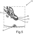
- the image section 12 of the camera image 10 is shown in a further representation, in addition to the already in connection with the 2 schematically indicated front edge 7, another front edge 13 of the ball head coupling have been optically marked or highlighted.
- the trailer coupling assistant 8 detects these curved front edges 7, 13 of the ball coupling 5 of the trailer 2 within the delimited image section 12.
- the image section 12 is first converted into a grayscale image.
- the detection of edges within the image section 12 and in particular the detection of the front edges 7, 13 is preferably carried out using the so-called Canny algorithm. This presupposes that the image section 12 is available as a grayscale image.
- the Canny algorithm is widely used in digital image processing Common, robust algorithm for edge detection. Using this algorithm, an image can be delivered which ideally only contains edges of the original image, ie of the image detail 12 .
- other image processing algorithms for edge detection are also possible.
- Multiple image processing operations are preferably used to detect different edges within the image detail 12 . All of these edges are filtered by various parameters in order ultimately to detect the two front edges 7, 13 that are optically highlighted here. For example, information regarding specific geometric features of the front edges 7, 13, such as specific curvatures and also their continuity, can be used to distinguish the front edges 7, 13 from other edges in the image section 12.
- the respective curvatures of the front edges 7, 13 are determined.
- An overall center point M of the leading edges 7, 13 is determined on the basis of the curvatures determined. This overall center point M is then set as the latching position P for the ball head 6 on the vehicle side.
- the respective center points of the curved front edges 7, 13, which are not described in any more detail here, are determined.
- an alignment of the trailer 2 to the motor vehicle 1, in particular to the reversing camera 9, can be taken into account in order to determine the overall center point M and thus ultimately the latching position P.
- the reversing camera 9 will only provide a pure top view of the ball head coupling 5 of the trailer 2 in the rarest of cases.
- the overall center point M can be determined with the aid of the detected front edges 7, 13, which then corresponds at least essentially to the overall center point of the spherically curved underside of the ball head coupling 5 of the trailer 2.
- a target position for the motor vehicle 1 can then be specified.
- the trailer coupling assistant 8 is designed to reverse the motor vehicle 1 semi-autonomously or fully autonomously towards the trailer 2, namely until the ball head 6 on the vehicle side has been positioned in the specific latching position P below the ball head coupling 5 of the trailer 2. Then the drawbar 4 only has to be moved downwards until the ball head 6 of the motor vehicle 1 has snapped into the ball head coupling 5 of the trailer 2 .
- a coupling process of the motor vehicle 1 to the trailer 2 when the motor vehicle 1 is driving backwards towards the trailer 2 can be particularly precisely supported.
- the invention is not limited purely to the use of the overall center point M of the front edges 7, 13, but generally includes the use of one or more front edges 7, 13 in a front area of the ball head coupling 5 of the trailer 2 as a reference for determining the exact latching position P for the ball head 6 of the motor vehicle 1.
Landscapes
- Engineering & Computer Science (AREA)
- Mechanical Engineering (AREA)
- Transportation (AREA)
- Physics & Mathematics (AREA)
- General Physics & Mathematics (AREA)
- Theoretical Computer Science (AREA)
- Multimedia (AREA)
- Computer Vision & Pattern Recognition (AREA)
- Length Measuring Devices By Optical Means (AREA)
- Image Analysis (AREA)
- Image Processing (AREA)
Description
- Die Erfindung betrifft ein Verfahren und einen Anhängerankuppelassistenten zum Unterstützen eines Ankuppelvorgangs eines rückwärts an einen Anhänger heranfahrenden Kraftfahrzeugs.
- Zum Ankuppeln eines Anhängers ist es notwendig, zielgerichtet mit einem Kraftfahrzeug zur Deichsel des Anhängers zu fahren. Bei leichten Anhängern reicht es aus, dass man grob in die Nähe der Deichsel fährt und dann den Anhänger zum Kraftfahrzeug schiebt, bis die Deichsel des Anhängers, genauer die so genannte Kugelkopfkupplung des Anhängers über einem so genannten Kugelkopf des Kraftfahrzeugs angeordnet ist, um dann den Anhänger anzukoppeln. Bei schwereren Anhängern ist eine solche Vorgehensweise nicht möglich. Das heißt, das Kraftfahrzeug muss zielgerichtet rückwärts an den Anhänger herangefahren werden, bis sich die Kugelkopfkupplung des Anhängers exakt über dem Kugelkopf des Kraftfahrzeugs befindet.
- Wesentlich hierbei ist die Bestimmung einer Einrastposition für den Kugelkopf des Kraftfahrzeugs, also einer entsprechenden Zielposition. Hieran werden hohe Anforderungen an die Genauigkeit gestellt. Der Kugelkopf der fahrzeugseitigen Anhängerkupplung hat üblicherweise einen Durchmesser von 5 Zentimetern. Das heißt, am Ende eines Rangiervorgangs muss die betreffende Anhängerdeichsel mindestens mit 2,5 Zentimeter Abstand zur fahrzeugseitigen Anhängerkupplung stehen, damit beim Herunterkurbeln der Anhängerdeichsel diese mit ihrer Kugelkopfkupplung direkt am Kugelkopf der Anhängerkupplung des Kraftfahrzeugs einrasten kann. Hierbei reicht die reine Erkennung der Deichsel an sich nicht aus. Es muss auch direkt die richtige Stelle der Anhängerdeichsel gefunden werden, an der der Kugelkopf der Anhängerkupplung des Kraftfahrzeugs einrasten kann.
- Verfahren zur Unterstützung eines Fahrers eines Kraftfahrzeugs bei einer Rückwärtsfahrt zum Ankuppeln eines Anhängers sind an sich schon bekannt. So zeigt beispielsweise die
DE 10 2014 212 041 A1 ein derartiges Verfahren. Dabei ist es vorgesehen, ein Kamerabild einer Rückfahrkamera anzuzeigen, wobei in Abhängigkeit von einem Lenkwinkel des Kraftfahrzeugs eine zugehörige Trajektorie so eingeblendet wird, dass ein Fahrer des Kraftfahrzeugs erkennen kann, ob jeweilige fahrzeugseitige und anhängerseitige Kupplungskomponenten nach der Rückwärtsfahrt übereinander zum Liegen kommen oder nicht. - Die
DE 10 2010 004 920 A1 beschreibt ein Verfahren zur Unterstützung eines Ankuppelvorgangs eines Anhängers an einer fahrzeugseitigen Anhängerkupplung eines Kraftfahrzeugs. Dabei ist es vorgesehen, eine Relativposition der Anhängerkupplung des Anhängers zur fahrzeugseitigen Anhängerkupplung des Kraftfahrzeugs durch Triangulation aus von mindestens zwei Abstandsmessgeräten gemessenen Abständen der Anhängerkupplung des Anhängers zu ermitteln. - Die
DE 10 2016 122 916 A1 zeigt ebenfalls ein Verfahren zur Unterstützung eines Ankuppelvorgangs eines Kraftfahrzeugs an einem Anhänger. Mittels einer Kamera wird dabei eine Position einer Anhängerkupplung des Anhängers im freien Raum in Bezug zu einem Kugelkopf einer fahrzeugseitigen Anhängerkupplung bestimmt. In diesem Zusammenhang ist es vorgesehen, mittels einer Positioniervorrichtung, bei welcher es sich um eine Lichtbarke zum Aussenden von Lichtsignalen oder um einen Schallwellensender zum Aussenden von Schallwellen handelt, für die Kamera erfassbare Positionssignale auszugeben. - Die
GB 2 513 393 A - Die
DE 10 2016 122 916 A1 betrifft ein geführtes Anhängerkupplungssteuerungssystem. Eine bildliche Erfassung einer Komponente wie zum Beispiel der Anhängerkupplung und der Kupplungskugel erfolgt mit einem Vorwissen der physikalischen Größe und relativen Positionierung des abgebildeten Ziels sowie der Messung der linearen Abstände zwischen den wichtigen Positionen auf dem erfassten Bild. Ein Prozessor kann einen linearen Abstand mit einem kalibrierten Pixelabstand zwischen identifizierten Kanten der dynamischen Pixelbilder messen. - Die
DE 10 2012 001 380 A1 betrifft ein Assistenzverfahren und ein Fahrerassistenzsystem für ein Ankuppelmanöver eines Kraftfahrzeugs. Dabei wird eine Bildauswerteeinheit zur Erkennung einer Kupplungspfanne verwendet. - Die
WO 2012/103193 A1 betrifft ein Rückblicksystem für ein Fahrzeug, das eine nach hinten gerichtete Kamera umfasst, die an einem hinteren Teil eines mit dem Rückblicksystem ausgestatteten Fahrzeugs angeordnet ist. Die nach hinten gerichtete Kamera ist in der Lage, Bilder hinter dem derart ausgestatteten Fahrzeug zu erfassen. Wenn sich ein Anhänger in der Nähe und/oder an dem derart ausgestatteten Fahrzeug befindet, kann ein Prozessor die aufgenommenen Bilder verarbeiten und zumindest teilweise als Reaktion auf diese Verarbeitung einen Anhängerwinkel des Anhängers relativ zu einer Längsachse des ausgerüsteten Fahrzeugs bestimmen. Ferner beschreibt dieWO 2012/103193 A1 eine Detektion von Rändern. Nachdem die Ränder detektiert wurden, wird eine Hough-Transformation verwendet, um Kreise zu detektieren. - Die
US 2009/0236825 A1 betrifft ein System zur Unterstützung der Ausrichtung eines am Heck eines Fahrzeugs montierten Kupplungsbolzens mit einer an der Vorderseite eines Anhängers montierten Kupplungsdose. Das System umfasst eine Kamera, die an dem Fahrzeug angebracht und so positioniert ist, dass sie ein Bild von der Rückseite des Fahrzeugs aufnimmt. Im Fahrzeug befindet sich ein Videodisplay, das das von der Kamera aufgenommene Bild anzeigt. Im Bild wird manuell eine Kupplungsdose gesucht und von einem Fadenkreuz ausgerichtet. Im Fahrzeug befindet sich auch ein Prozessor, der einen bevorzugten Fahrweg des Fahrzeugs berechnet, um den Kupplungsbolzen in Ausrichtung mit dem Kupplungssockel zu positionieren. Der Prozessor ist so programmiert, dass er dem Fahrer des Fahrzeugs Anweisungen für die erforderliche Lenkung gibt, um das Fahrzeug auf dem bevorzugten Fahrweg zu halten. Der Prozessor berechnet den bevorzugten Fahrweg immer dann neu, wenn das Fahrzeug um einen voreingestellten Schwellenwert vom bevorzugten Fahrweg abweicht. - Es ist die Aufgabe der vorliegenden Erfindung, eine Möglichkeit bereitzustellen, mittels welcher ein Ankuppelvorgang eines rückwärts an einen Anhänger heranfahrenden Kraftfahrzeugs besonders exakt erfolgen kann.
- Diese Aufgabe wird durch ein Verfahren sowie durch einen Anhängerankupplungsassistenten zum Unterstützen eines Ankuppelvorgangs mit den Merkmalen der unabhängigen Patentansprüche gelöst. Vorteilhafte Ausgestaltungen mit zweckmäßigen und nicht-trivialen Weiterbildungen der Erfindung sind in den abhängigen Ansprüchen angegeben.
- Bei dem erfindungsgemäßen Verfahren zum Unterstützen eines Ankuppelvorgangs eines rückwärts an einen Anhänger heranfahrenden Kraftfahrzeugs wird eine Kugelkopfkupplung des Anhängers anhand eines mittels einer Kamera des Kraftfahrzeugs aufgezeichneten Kamerabilds erfasst. Das Kamerabild wird danach auf einen Bildausschnitt eingegrenzt, in welchem sich die Kugelkopfkupplung befindet. Wenigstens eine gekrümmte Vorderkante der Kugelkopfkupplung wird innerhalb des eingegrenzten Bildausschnitts detektiert, wobei die Einrastposition für einen fahrzeugseitigen Kugelkopf anhand der wenigstens einen detektierten gekrümmten Vorderkante der Kugelkopfkupplung bestimmt wird.
- Die wenigstens eine detektierte Vorderkante der anhängerseitigen Kugelkopfkupplung dient also mit anderen Worten als Referenzgeometrie bei der Bestimmung der Einrastposition für den fahrzeugseitigen Kugelkopf. Mittels der fahrzeugseitigen Kamera wird eine Deichsel und die daran angeordnete Kugelkopfkupplung automatisch erkannt, um basierend darauf automatisch die besagte Einrastposition für den fahrzeugseitigen Kugelkopf zu bestimmen. In einem ersten Schritt wird eine grobe Position des Anhängers und somit der Kugelkopfkupplung des Anhängers bestimmt. Dies erfolgt vorzugsweise basierend auf einer Eckenerkennung. Dies reicht aus, um mit dem Kraftfahrzeug rückwärts an den Anhänger heranzufahren und einen Abstand zwischen der Kugelkopfkupplung des Anhängers und dem fahrzeugseitigen Kugelkopf auf wenige Dezimeter zu verringern, jedoch noch nicht, um das Kraftfahrzeug so zu positionieren, dass ein Einrasten des Kugelkopfs der fahrzeugseitigen Anhängerkupplung zuverlässig erfolgen kann. Daher wird in einem weiteren Schritt die zuvor grob bestimmte Position der Kugelkopfkupplung des Anhängers verwendet, um den Bildausschnitt, in dem sich die Kugelkopfkupplung befindet, einzugrenzen. Mit anderen Worten erfolgt also die Eingrenzung des Kamerabilds auf den Bildausschnitt auf Basis der zuvor erfassten Kugelkopfkupplung des Anhängers.
- In diesem Bildausschnitt werden nun mit Hilfe einer Bildverarbeitungsoperation, vorzugsweise mittels mehrerer Bildverarbeitungsoperationen, verschiedenste Kanten detektiert. Diese Kanten werden durch verschiedene Parameter gefiltert, um letztlich die wenigstens eine gekrümmte Vorderkante der Kugelkopfkupplung innerhalb des eingegrenzten Bildausschnitts zu detektieren. Beispielsweise werden hierzu ganz bestimmte geometrische Eigenschaften der gekrümmten Vorderkante, wie beispielsweise eine bestimmte Krümmung eines Kurvenverlaufs der gekrümmten Vorderkante sowie eine bestimmte Stetigkeit der Krümmung genutzt. Mit Hilfe der wenigstens einen detektierten gekrümmten Vorderkante der Kugelkopfkupplung des Anhängers wird sodann die exakte Einrastposition für den fahrzeugseitigen Kugelkopf bestimmt. Diese bestimmte Einrastposition für den fahrzeugseitigen Kugelkopf kann dann als exakte Zielposition für das Kraftfahrzeug verwendet werden. Beispielsweise ist es möglich, einen automatischen Rangiervorgang des Kraftfahrzeugs in Abhängigkeit von der bestimmten Einrastposition für den fahrzeugseitigen Kugelkopf durchzuführen. In dem Fall wäre es möglich, dass das Kraftfahrzeug teilautonom oder vollautonom rückwärts an den anzukuppelnden Anhänger heranfährt, bis der fahrzeugseitige Kugelkopf der fahrzeugseitigen Anhängerkupplung die bestimmte Einrastposition erreicht hat.
- Es ist also erfindungsgemäß vorgesehen, einen Zusammenhang zwischen der wenigstens einen gekrümmten, also kurvenförmigen Vorderkante der Kugelkopfkupplung oder auch anderer Kanten in einem vorderen Bereich der Kugelkopfkupplung und der Einrastposition für den fahrzeugseitigen Kugelkopf herzustellen, um letztlich die exakte Einrastposition für den fahrzeugseitigen Kugelkopf zu bestimmen. Mittels des erfindungsgemäßen Verfahrens ist es auf besonders exakte Weise möglich, die besagte Einrastposition für den fahrzeugseitigen Kugelkopf zu bestimmen. Insbesondere schwere Anhänger, welche nicht manuell an das Kraftfahrzeug herangeschoben werden können, können mittels des erfindungsgemäßen Verfahrens besonders exakt angekuppelt werden. Denn in Kenntnis der bestimmten Einrastposition für den fahrzeugseitigen Kugelkopf ist es auf einfache Weise möglich, eine Zielposition für das Kraftfahrzeug beim Heranfahren an den anzuhängenden Anhänger vorzugeben.
- Eine vorteilhafte Ausführungsform der Erfindung sieht vor, dass das Kamerabild erst auf den Bildausschnitt eingegrenzt wird, sobald ein vorgegebener Abstand zwischen der Kugelkopfkupplung und dem Kraftfahrzeug durch Heranbewegen des Kraftfahrzeugs unterschritten worden ist. Beispielsweise ist es möglich, diesen Abstand mit 10, 20 oder 30 Zentimetern vorzugeben. Grundsätzlich wird der Abstand so vorgegeben, dass eine gewisse Genauigkeit beim Detektieren der wenigstens einen gekrümmten Vorderkante der Kugelkopfkupplung möglich ist. Wenn das Kraftfahrzeug also rückwärts nah genug an die Kugelkopfkupplung herangefahren ist, erfolgt die Eingrenzung des Kamerabilds auf den Bildausschnitt. Denn je näher das Kraftfahrzeug rückwärts an den Anhänger heranfährt, desto mehr ergibt sich eine Draufsicht auf die Kugelkopfkupplung des Anhängers, aufgrund der üblicherweise vorgesehenen Positionierung der Kamera, bei welcher es sich vorzugsweise um eine Rückfahrkamera des Kraftfahrzeugs handelt. Dadurch, dass der Bildausschnitt erst dann eingegrenzt wird, sobald der vorgegebene Abstand zwischen der Kugelkopfkupplung und dem Kraftfahrzeug unterschritten worden ist, kann sichergestellt werden, dass die Perspektive des Kamerabilds zumindest im Wesentlichen einer Draufsicht auf die Kugelkopfkupplung des Anhängers gleicht. Dies ermöglicht eine besonders exakte Bestimmung der Einrastposition für den fahrzeugseitigen Kugelkopf.
- Erfindungsgemäß ist vorgesehen, dass eine Krümmung der wenigstens einen Vorderkante ermittelt und die Einrastposition in Abhängigkeit von der ermittelten Krümmung bestimmt wird. Der Erfindung liegt dabei die Erkenntnis zugrunde, dass die Krümmung der wenigstens einen Vorderkante mit der Einrastposition für den fahrzeugseitigen Kugelkopf relativ zur Kugelkopfkupplung des Anhängers korreliert. Durch die Berücksichtigung der Krümmung der wenigstens einen Vorderkante bei der Bestimmung der Einrastposition kann diese besonders exakt ermittelt werden.
- Erfindungsgemäß ist weiter vorgesehen, dass anhand der ermittelten Krümmung der wenigstens einen Vorderkante ein Mittelpunkt der Vorderkante bestimmt und dieser als die Einrastposition für den fahrzeugseitigen Kugelkopf festgelegt wird. Insbesondere wird der Mittelpunkt bezogen auf eine Querrichtung und Längsrichtung der Kugelkopfkupplung des Anhängers bestimmt, sodass sich die Einrastposition für den fahrzeugseitigen Kugelkopf zumindest im Wesentlichen mittig unter der vorzugsweise kugelschalenförmigen Kugelkopfkupplung des Anhängers befindet.
- In weiterer vorteilhafter Ausgestaltung der Erfindung ist es vorgesehen, dass statische Bereiche des Kamerabilds, insbesondere eine Heckstoßstange des Kraftfahrzeugs, maskiert werden. Solche statischen Bereiche des Kamerabilds, beispielsweise in Form der Heckstoßstange des Kraftfahrzeugs, sind bei der Bestimmung der Einrastposition für den fahrzeugseitigen Kugelkopf nicht wichtig und können gegebenenfalls sogar störend sein. Daher ist es von Vorteil, wenn solche statischen Bereiche des Kamerabilds maskiert werden, sodass solche Bereiche die Bestimmung der Einrastposition für den fahrzeugseitigen Kugelkopf nicht beeinflussen beziehungsweise stören.
- Eine weitere vorteilhafte Ausführungsform der Erfindung sieht vor, dass der Bildausschnitt in ein Graustufenbild umgewandelt wird, bevor die wenigstens eine Vorderkante detektiert wird. Dies ist insbesondere ein Vorteil im Hinblick auf verschiedenste Bildverarbeitungsalgorithmen zur Kantendetektion. Denn gewisse Bildverarbeitungsalgorithmen funktionieren erst oder zumindest besser, wenn das auszuwertende Bild nur in Graustufen vorliegt. Dadurch kann die Einrastposition für den fahrzeugseitigen Kugelkopf besonders exakt bestimmt werden.
- In weiterer vorteilhafter Ausgestaltung der Erfindung ist es vorgesehen, dass die wenigstens eine Vorderkante mittels des Canny-Algorithmus detektiert wird. Der Canny-Algorithmus ist ein in der digitalen Bildverarbeitung weit verbreiteter, robuster Algorithmus zur Kantendetektion. Er gliedert sich in verschiedene Faltungsoperationen und liefert ein Bild, welches idealerweise nur noch die Kanten des Ausgangsbildes enthält. Mittels des Canny-Algorithmus kann die zumindest eine Vorderkante der Kugelkopfkupplung besonders zuverlässig detektiert werden. Infolgedessen kann unter Verwendung des Canny-Algorithmus auch die Einrastposition für den fahrzeugseitigen Kugelkopf besonders exakt bestimmt werden. Es sind jedoch auch andere Bildverarbeitungsalgorithmen zur Kantenerkennung möglich.
- Erfindungsgemäß ist vorgesehen, dass zumindest eine weitere Vorderkante der Kugelkopfkupplung innerhalb des eingegrenzten Bildausschnitts detektiert und die Einrastposition für den fahrzeugseitigen Kugelkopf anhand der beiden detektierten Vorderkanten bestimmt wird. Dabei werden jeweilige Krümmungen der Vorderkanten ermittelt, anhand der ermittelten Krümmungen ein Gesamtmittelpunkt der Vorderkanten bestimmt und dieser Gesamtmittelpunkt als die Einrastposition für den fahrzeugseitigen Kugelkopf festgelegt. Es ist von Vorteil, mehrere Vorderkanten der Kugelkopfkupplung bei der Bestimmung der Einrastposition für den fahrzeugseitigen Kugelkopf zu berücksichtigen. Insbesondere wenn Krümmungen von mehreren Vorderkanten ermittelt und basierend darauf der besagte Gesamtmittelpunkt der Vorderkanten bestimmt sowie dieser Gesamtmittelpunkt als die Einrastposition für den fahrzeugseitigen Kugelkopf festgelegt wird, kann die Einrastposition für den fahrzeugseitigen Kugelkopf besonders exakt bestimmt werden. Beispielsweise können so aufgrund der Position der fahrzeugseitigen Kamera vorhandene perspektivische Verzerrungen beim Erfassen der Kugelkopfkupplung und letztlich der Vorderkanten der Kugelkopfkupplungen gegebenenfalls kompensiert werden, sodass die Einrastposition für den fahrzeugseitigen Kugelkopf besonders exakt bestimmt werden kann.
- Der erfindungsgemäße Anhängerankuppelassistent für ein Kraftfahrzeug ist dazu eingerichtet, das erfindungsgemäße Verfahren und eine vorteilhafte Ausführungsform des erfindungsgemäßen Verfahrens durchzuführen. Vorteilhafte Ausgestaltungen des erfindungsgemäßen Verfahrens sind als vorteilhafte Ausgestaltungen des erfindungsgemäßen Anhängerankuppelassistenten und umgekehrt anzusehen, wobei der Anhängerankuppelassistent insbesondere Mittel zur Durchführung der Verfahrensschritte aufweist. Ferner kann der Anhängerankuppelassistent eine Bildverarbeitungseinrichtung aufweisen, welche dazu eingerichtet ist, die Verfahrensschritte durchzuführen. Der Anhängerankuppelassistent weist vorzugsweise eine Datenschnittstelle auf, um Bilddaten von der fahrzeugseitigen Kamera zu empfangen. Auch kann der Anhängerankuppelassistent beispielsweise als Nachrüstlösung ausgebildet sein, welche - entsprechende fahrzeugseitige Schnittstellen vorausgesetzt - einfach in beliebigen Kraftfahrzeugen nachgerüstet werden kann. Natürlich ist es auch möglich, dass der Anhängerankuppelassistent von vornerein bei der Produktion eines Kraftfahrzeugs vorgesehen wird.
- Das erfindungsgemäße Kraftfahrzeug umfasst den erfindungsgemäßen Anhängerankuppelassistenten oder eine vorteilhafte Ausführungsform des erfindungsgemäßen Anhängerankuppelassistenten.
- Weitere Vorteile, Merkmale und Einzelheiten der Erfindung ergeben sich aus der nachfolgenden Beschreibung eines bevorzugten Ausführungsbeispiels sowie anhand der Zeichnung. Die vorstehend in der Beschreibung genannten Merkmale und Merkmalskombinationen sowie die nachfolgend in der Figurenbeschreibung genannten und/oder in den Figuren alleine gezeigten Merkmale und Merkmalskombinationen sind nicht nur in der jeweils angegebenen Kombination, sondern auch in anderen Kombinationen oder in Alleinstellung verwendbar, ohne den Rahmen der Erfindung zu verlassen.
- Die Zeichnung zeigt in:
- Fig. 1
- eine Draufsicht auf einen Ankuppelvorgang eines rückwärts an einen Anhänger heranfahrenden Kraftfahrzeugs;
- Fig. 2
- eine Seitenansicht des Kraftfahrzeugs, nachdem dieses an den Anhänger angekuppelt worden ist;
- Fig. 3
- ein mittels einer Rückfahrkamera des Kraftfahrzeugs aufgezeichnetes Kamerabild während das Kraftfahrzeug rückwärts an den Anhänger heranfährt;
- Fig. 4
- einen eingegrenzten Bildausschnitt des mittels der Rückfahrkamera aufgezeichneten Kamerabilds, in welchem eine Kugelkopfkupplung des Anhängers und ein fahrzeugseitiger Kugelkopf zu erkennen sind; und in
- Fig. 5
- eine weitere Darstellung des eingegrenzten Bildausschnitts, wobei zwei detektierte Vorderkanten der Kugelkopfkupplung des Anhängers optisch hervorgehoben sind, die zur Bestimmung einer Einrastposition für den fahrzeugseitigen Kugelkopf dienen.
- In den Figuren sind gleiche oder funktionsgleiche Elemente mit den gleichen Bezugszeichen versehen worden.
- Ein Ankuppelvorgang eines rückwärtsfahrenden Kraftfahrzeugs 1 an einen Anhänger 2 ist in einer Draufsicht in
Fig. 1 gezeigt. Das Kraftfahrzeug 1 fährt dabei eine schematisch angedeutete Trajektorie 3 ab, um sich einer Deichsel 4 des Anhängers 2 zu nähern, an deren Vorderseite eine Kugelkopfkupplung 5 angeordnet ist. Im vorliegend gezeigten Ausführungsbeispiel soll davon ausgegangen werden, dass der Anhänger 2 so schwer ist, dass dieser nicht ohne weiteres manuell, also von Hand, rangiert werden kann. Daher ist es erforderlich, dass das Kraftfahrzeug 1 ganz exakt an die Kugelkopfkupplung 5 des Anhängers 2 herangefahren wird, sodass die Deichsel 4 danach lediglich noch abgesenkt werden muss, um den Anhänger 2 an das Kraftfahrzeug 1 anzukuppeln. - In
Fig. 2 ist das Kraftfahrzeug 1 nach dem Ankuppeln an den Anhänger 2 in einer Seitenansicht gezeigt. Ein fahrzeugseitiger Kugelkopf 6 ist dabei in einer Einrastposition P unterhalb der Deichsel 4 positioniert worden, sodass die Deichsel 4 mit ihrer vorliegend nicht dargestellten Kugelkopfkupplung 5 lediglich noch abgesenkt werden musste, damit der fahrzeugseitige Kugelkopf 6 in die Kugelkopfkupplung 5 des Anhängers 2 einrasten beziehungsweise einschnappen konnte. Eine Vorderkante 7 der hier nicht näher bezeichneten Kugelkopfkupplung 5 des Anhängers 2 ist zudem noch schematisch angedeutet. - Um die besagte Einrastposition P für den fahrzeugseitigen Kugelkopf 6 besonders exakt bestimmen zu können, weist das Kraftfahrzeug 1 einen Anhängerankuppelassistenten 8 auf, welcher dazu eingerichtet ist, die Einrastposition P für den fahrzeugseitigen Kugelkopf 6 zu bestimmen. Des Weiteren ist eine Rückfahrkamera 9 des Kraftfahrzeugs 1 schematisch angedeutet. Der Anhängerankuppelassistent 8 und die Rückfahrkamera 9 sind signaltechnisch miteinander verbunden, sodass der Anhängerankuppelassistent 8 Bildsignale von der Rückfahrkamera 9 empfangen und auswerten kann. Anhand der nachfolgenden Figuren wird ein Verfahren zum Unterstützen des Ankuppelvorgangs des Anhängers 2 an das Kraftfahrzeug 1 näher beschrieben.
- In
Fig. 3 ist ein mittels der Rückfahrkamera 9 aufgezeichnetes Kamerabild 10 gezeigt. In dem Kamerabild 10 ist der rückseitig mit dem Kraftfahrzeug 1 angeordnete Anhänger 2 mitsamt seiner Deichsel 4 und der daran angeordneten Kugelkopfkupplung 5 zu erkennen. Ferner kann man noch den fahrzeugseitigen Kugelkopf 6 innerhalb des Kamerabilds 10 sowie eine Heckstoßstange 11 des Kraftfahrzeugs 1 sehen. Mittels des Anhängerankuppelassistenten 8 wird anhand des mittels der Rückfahrkamera 9 aufgezeichneten Kamerabilds 10 die Kugelkopfkupplung 5 des Anhängers 2 und insbesondere auch die Position der Kugelkopfkupplung 5 erfasst beziehungsweise ermittelt. Statische Bereiche des Kamerabilds 10, insbesondere die Heckstoßstange 11, werden anschließend maskiert. Denn die Heckstoßstange 11 oder auch andere Komponenten des Kraftfahrzeugs 1 sind bei der Ermittlung der Einrastposition P für den fahrzeugseitigen Kugelkopf 6 nicht weiter von Interesse und können sogar störend sein. Daher werden solche statischen Bereiche maskiert beziehungsweise anderweitig ausgeblendet. - In
Fig. 4 ist ein Bildausschnitt 12 des Kamerabilds 10 gezeigt. Sobald das Kraftfahrzeug 1 einen vorgegebenen Abstand zu der erfassten Kugelkopfkupplung 5 unterschritten hat, wird das Kamerabild 10 auf den hier inFig. 4 gezeigten Bildausschnitt 12 eingegrenzt. Dies kann beispielsweise dann erfolgen, wenn ein Abstand zwischen dem fahrzeugseitigen Kugelkopf 6 und der Kugelkopfkupplung 5, 10, 20 oder 30 Zentimeter unterschritten hat. Der Abstand, ab welchem das Kamerabild 10 auf den Bildausschnitt 12 eingegrenzt wird, kann beispielsweise in Abhängigkeit von der Positionierung der Rückfahrkamera 9 des Kraftfahrzeugs 1 festgelegt werden. Wichtig für die exakte Bestimmung der korrekten Einrastposition P des fahrzeugseitigen Kugelkopfs 6 ist dabei unter anderem, wie stark beziehungsweise wie sehr in dem Bildausschnitt 12 des Kamerabilds 10 die Kugelkopfkupplung 5 in einer Draufsicht erkennbar ist. Je näher nämlich das Kraftfahrzeug 1 rückwärts an den Anhänger 2 heranfährt, desto mehr verändert sich die Perspektive des Kamerabilds 10 zu einer Draufsicht auf die Kugelkopfkupplung 5. - In
Fig. 5 ist der Bildausschnitt 12 des Kamerabilds 10 in einer weiteren Darstellung gezeigt, wobei neben der bereits in Zusammenhang mit derFig. 2 schematisch angedeuteten Vorderkante 7 noch eine weitere Vorderkante 13 der Kugelkopfkupplung optisch markiert beziehungsweise hervorgehoben worden sind. Der Anhängerankuppelassistent 8 detektiert diese gekrümmten Vorderkanten 7, 13 der Kugelkopfkupplung 5 des Anhängers 2 innerhalb des eingegrenzten Bildausschnitts 12. Um diese Vorderkanten 7, 13 besonders zuverlässig erkennen zu können, wird der Bildausschnitt 12 zunächst in ein Graustufenbild umgewandelt. Die Erkennung von Kanten innerhalb des Bildausschnitts 12 und insbesondere die Erkennung der Vorderkanten 7, 13 erfolgt vorzugsweise mittels des so genannten Canny-Algorithmus. Dieser setzt voraus, dass der Bildausschnitt 12 als Graustufenbild vorliegt. Der Canny-Algorithmus ist ein in der digitalen Bildverarbeitung weit verbreiteter, robuster Algorithmus zur Kantendetektion. Unter Verwendung dieses Algorithmus kann ein Bild geliefert werden, welches idealerweise nur noch Kanten des Ausgangsbildes, also des Bildausschnitts 12, enthält. Andere Bildverarbeitungsalgorithmen zur Kantendetektion sind aber ebenfalls möglich. - Vorzugsweise werden mehrere Bildverarbeitungsoperationen verwendet, um verschiedene Kanten innerhalb des Bildausschnitts 12 zu detektieren. Die Gesamtheit dieser Kanten wird durch verschiedene Parameter gefiltert, um letztlich die beiden hier optisch hervorgehobenen Vorderkanten 7, 13 zu detektieren. Dabei können beispielsweise Informationen hinsichtlich bestimmter geometrischer Merkmale der Vorderkanten 7, 13, wie z.B. bestimmte Krümmungen und auch ihre Stetigkeiten, genutzt werden, um die Vorderkanten 7, 13 von anderen Kanten im Bildausschnitt 12 zu unterscheiden.
- Innerhalb des Bildausschnitts 12 werden jeweilige Krümmungen der Vorderkanten 7, 13 ermittelt. Anhand der ermittelten Krümmungen wird ein Gesamtmittelpunkt M der Vorderkanten 7, 13 bestimmt. Dieser Gesamtmittelpunkt M wird dann als die Einrastposition P für den fahrzeugseitigen Kugelkopf 6 festgelegt.
- Dafür werden beispielsweise jeweilige, hier nicht näher bezeichnete Mittelpunkte der kurvenförmigen Vorderkanten 7, 13 bestimmt. Zudem kann beispielsweise auch eine Ausrichtung des Anhängers 2 zum Kraftfahrzeug 1, insbesondere zur Rückfahrkamera 9, berücksichtigt werden, um den Gesamtmittelpunkt M und somit letztlich die Einrastposition P zu bestimmen. Denn die Rückfahrkamera 9 wird in den seltensten Fällen eine reine Draufsicht auf die Kugelkopfkupplung 5 des Anhängers 2 liefern. Unter Berücksichtigung der Kameraperspektive der Rückfahrkamera 9 kann unter Zuhilfenahme der erkannten Vorderkanten 7, 13 der Gesamtmittelpunkt M bestimmt werden, welcher dann zumindest im Wesentlichen dem Gesamtmittelpunkt der kugelförmig gekrümmten Unterseite der Kugelkopfkupplung 5 des Anhängers 2 entspricht.
- In Kenntnis der so bestimmten Einrastposition P kann dann eine Zielposition für das Kraftfahrzeug 1 vorgegeben werden. Beispielsweise ist es denkbar, dass der Anhängerankuppelassistent 8 dazu ausgelegt ist, das Kraftfahrzeug 1 teilautonom oder vollautonom rückwärts an den Anhänger 2 heranzufahren, und zwar bis der fahrzeugseitige Kugelkopf 6 in der bestimmten Einrastposition P unterhalb von der Kugelkopfkupplung 5 des Anhängers 2 positioniert worden ist. Anschließend muss die Deichsel 4 lediglich noch nach unten bewegt werden, bis der Kugelkopf 6 des Kraftfahrzeugs 1 in die Kugelkopfkupplung 5 des Anhängers 2 eingerastet ist.
- Mit Hilfe des beschriebenen Verfahrens und des beschriebenen Anhängerankuppelassistenten 8 kann also ein Ankuppelvorgang des Kraftfahrzeugs 1 an den Anhänger 2 beim rückwärts Heranfahren des Kraftfahrzeugs 1 an den Anhänger 2 besonders exakt unterstützt werden. Die Erfindung beschränkt sich dabei nicht rein auf die Verwendung des Gesamtmittelpunkts M der Vorderkanten 7, 13, sondern beinhaltet allgemein die Verwendung einer oder auch mehrerer Vorderkanten 7, 13 in einem vorderen Bereich der Kugelkopfkupplung 5 des Anhängers 2 als Referenz zur Bestimmung der genauen Einrastposition P für den Kugelkopf 6 des Kraftfahrzeugs 1.
-
- 1
- Kraftfahrzeug
- 2
- Anhänger
- 3
- Trajektorie
- 4
- Anhängerdeichsel
- 5
- Kugelkopfkupplung des Anhängers
- 6
- Kugelkopf des Kraftfahrzeugs
- 7
- Vorderkante der Kugelkopfkupplung
- 8
- Anhängerankuppelassistent
- 9
- Rückfahrkamera
- 10
- Kamerabild der Rückfahrkamera
- 11
- Heckstoßstange des Kraftfahrzeugs
- 12
- Bildausschnitt des Kamerabilds der Rückfahrkamera
- 13
- Vorderkante der Kugelkopfkupplung
- M
- Gesamtmittelpunkt
- P
- Einrastposition für den Kugelkopf des Kraftfahrzeugs
Claims (7)
- Verfahren zum Unterstützen eines Ankuppelvorgangs eines rückwärts an einen Anhänger (2) heranfahrenden Kraftfahrzeugs (1), mit den Schritten:- Erfassen einer Kugelkopfkupplung (5) des Anhängers (2) anhand eines mittels einer Kamera des Kraftfahrzeugs (1) aufgezeichneten Kamerabilds (10);- Eingrenzen des Kamerabilds (10) auf einen Bildausschnitt (12), in welchem sich die Kugelkopfkupplung (5) befindet;
gekennzeichnet durch folgende weiteren Schritte:- Detektieren wenigstens einer gekrümmten Vorderkante (7) der Kugelkopfkupplung (5) innerhalb des eingegrenzten Bildausschnitts (12), wobei zunächst mittels mindestens einer Bildverarbeitungsoperation Kanten detektiert werden und diese anschließend durch verschiedene Parameter gefiltert werden;- Bestimmen der Einrastposition (P) für einen fahrzeugseitigen Kugelkopf (6) anhand der wenigstens einen detektierten gekrümmten Vorderkante (7, 13) der Kugelkopfkupplung (5), wobei eine Krümmung der wenigstens einen Vorderkante (7) ermittelt und die Einrastposition (P) in Abhängigkeit von der ermittelten Krümmung bestimmt wird, wobei anhand der ermittelten Krümmung der wenigstens einen Vorderkante (7) ein Mittelpunkt der Vorderkante (7, 13) bestimmt und dieser als die Einrastposition (P) für den fahrzeugseitigen Kugelkopf (6) festgelegt wird;- wobei zumindest eine weitere Vorderkante (13) der Kugelkopfkupplung (5) innerhalb des eingegrenzten Bildausschnitts (12) detektiert und die Einrastposition (P) für den fahrzeugseitigen Kugelkopf (6) anhand der beiden detektierten Vorderkanten (7, 13) bestimmt wird, und- wobei jeweilige Krümmungen der Vorderkanten (7, 13) ermittelt werden, anhand der ermittelten Krümmungen ein Gesamtmittelpunkt (M) der Vorderkanten (7, 13) bestimmt und dieser Gesamtmittelpunkt (M) als die Einrastposition (P) für den fahrzeugseitigen Kugelkopf (6) festgelegt wird. - Verfahren nach Anspruch 1,
dadurch gekennzeichnet, dass
das Kamerabild (10) erst auf den Bildausschnitt (12) eingegrenzt wird, sobald ein vorgegebener Abstand zwischen der Kugelkopfkupplung (5) und dem Kraftfahrzeug (1) durch Heranbewegen des Kraftfahrzeugs (1) unterschritten worden ist. - Verfahren nach einem der vorhergehenden Ansprüche,
dadurch gekennzeichnet, dass
statische Bereiche des Kamerabilds (10), insbesondere eine Heckstoßstange (11) des Kraftfahrzeugs (1), maskiert werden. - Verfahren nach einem der vorhergehenden Ansprüche,
dadurch gekennzeichnet, dass
der Bildausschnitt (12) in ein Graustufenbild umgewandelt wird, bevor die wenigstens eine Vorderkante (7) detektiert wird. - Verfahren nach Anspruch 4,
dadurch gekennzeichnet, dass
die wenigstens eine Vorderkante (7) mittels des Canny-Algorithmus detektiert wird. - Anhängerankuppelassistent (8) für ein Kraftfahrzeug (1), umfassend Mittel zur Ausführung des Verfahrens nach einem der vorhergehenden Ansprüche.
- Kraftfahrzeug (1) mit einem Anhängerankuppelassistenten (8) nach Anspruch 6.
Applications Claiming Priority (2)
| Application Number | Priority Date | Filing Date | Title |
|---|---|---|---|
| DE102017220459.1A DE102017220459B4 (de) | 2017-11-16 | 2017-11-16 | Verfahren und Anhängerankuppelassistent zum Unterstützen eines Ankuppelvorgangs eines rückwärts an einen Anhänger heranfahrenden Kraftfahrzeugs, sowie Kraftfahrzeug |
| PCT/EP2018/080967 WO2019096746A1 (de) | 2017-11-16 | 2018-11-12 | Verfahren und anhängerankuppelassistent zum unterstützen eines ankuppelvorgangs eines rückwärts an einen anhänger heranfahrenden kraftfahrzeugs |
Publications (2)
| Publication Number | Publication Date |
|---|---|
| EP3710288A1 EP3710288A1 (de) | 2020-09-23 |
| EP3710288B1 true EP3710288B1 (de) | 2023-04-05 |
Family
ID=64316532
Family Applications (1)
| Application Number | Title | Priority Date | Filing Date |
|---|---|---|---|
| EP18803622.2A Active EP3710288B1 (de) | 2017-11-16 | 2018-11-12 | Verfahren und anhängerankuppelassistent zum unterstützen eines ankuppelvorgangs eines rückwärts an einen anhänger heranfahrenden kraftfahrzeugs |
Country Status (4)
| Country | Link |
|---|---|
| US (1) | US11186224B2 (de) |
| EP (1) | EP3710288B1 (de) |
| DE (1) | DE102017220459B4 (de) |
| WO (1) | WO2019096746A1 (de) |
Families Citing this family (6)
| Publication number | Priority date | Publication date | Assignee | Title |
|---|---|---|---|---|
| DE102019213223A1 (de) * | 2019-09-02 | 2021-03-04 | Volkswagen Aktiengesellschaft | Kollisionsvermeidung bei Annäherung eines Fahrzeugs an eine Anhängerdeichsel |
| US12286156B2 (en) * | 2020-05-08 | 2025-04-29 | Ford Global Technologies, Llc | Trailer GPS location storage and recall for hitch assist operation |
| DE102020003141A1 (de) * | 2020-05-26 | 2021-12-02 | Jost-Werke Deutschland Gmbh | Fahrerassistenzsystem und Verfahren zum Ankuppeln eines Anhängers an ein Zugfahrzeug |
| DE102020211549A1 (de) | 2020-09-15 | 2022-03-17 | Volkswagen Aktiengesellschaft | Automatisches Auswählen einer aus einer Mehrzahl von Parkassistenzfunktionen bei einem Kraftfahrzeug |
| US11676300B2 (en) * | 2020-12-09 | 2023-06-13 | Continental Autonomous Mobility US, LLC | Method for real-time tow ball detection |
| DE102021212176B3 (de) * | 2021-10-28 | 2022-10-06 | Volkswagen Aktiengesellschaft | Verfahren zum Bereitstellen einer Anzeige in einem Kraftfahrzeug sowie Kraftfahrzeug |
Citations (2)
| Publication number | Priority date | Publication date | Assignee | Title |
|---|---|---|---|---|
| US20090236825A1 (en) * | 2008-03-20 | 2009-09-24 | Toyota Motor Engineering & Manufacturing North America, Inc. | System for assisting the attachment of a trailer to a vehicle |
| WO2012103193A1 (en) * | 2011-01-26 | 2012-08-02 | Magna Electronics Inc. | Rear vision system with trailer angle detection |
Family Cites Families (25)
| Publication number | Priority date | Publication date | Assignee | Title |
|---|---|---|---|---|
| US7568716B2 (en) * | 2005-05-13 | 2009-08-04 | Dietz Dan L | Method and apparatus for alignment of trailer hitch |
| US20070216136A1 (en) * | 2006-03-15 | 2007-09-20 | Dietz Dan L | Single camera apparatus and methods for alignment of a trailer hitch |
| US8888121B2 (en) * | 2007-01-25 | 2014-11-18 | Target Hitch Llc | Towing vehicle guidance for trailer hitch connection |
| WO2009006529A1 (en) | 2007-07-03 | 2009-01-08 | Ramsey J Edward | Trailer hitch alignment device and method |
| DE102009029439A1 (de) | 2009-09-14 | 2011-03-24 | Robert Bosch Gmbh | Verfahren und Vorrichtung zur Darstellung von Hindernissen in einem Einparkhilfesystem von Kraftfahrzeugen |
| DE102010004920A1 (de) | 2010-01-19 | 2011-07-21 | ZF Lenksysteme GmbH, 73527 | Vorrichtung zur Unterstützung des Ankuppelns eines Anhängers an eine Anhängerkupplung eines Kraftfahrzeugs und Verfahren |
| DE102012001380A1 (de) | 2012-01-24 | 2012-08-02 | Daimler Ag | Assistenzverfahren und Fahrerassistenzsystem für ein Ankuppelmanöver eines Kraftfahrzeugs |
| DE102012005707A1 (de) | 2012-03-20 | 2012-10-18 | Daimler Ag | Anhängerankuppelverfahren eines Kraftfahrzeugs unter automatischem Querführen des Kraftfahrzeugs |
| US20140125795A1 (en) * | 2012-11-05 | 2014-05-08 | James Arnold Yerke | Trailer Coupling Assistant |
| GB2513393B (en) | 2013-04-26 | 2016-02-03 | Jaguar Land Rover Ltd | Vehicle hitch assistance system |
| US20150115571A1 (en) * | 2013-10-24 | 2015-04-30 | GM Global Technology Operations LLC | Smart tow |
| CN105082910B (zh) * | 2014-05-07 | 2018-01-26 | 通用汽车环球科技运作有限责任公司 | 辅助将运载工具联接至拖车的系统和方法 |
| DE102014212041A1 (de) | 2014-06-24 | 2015-12-24 | Robert Bosch Gmbh | Verfahren zur Unterstützung des Fahrers eines Kraftfahrzeugs bei einer Rückwärtsfahrt zum Ankuppeln eines Anhängers |
| US10259453B2 (en) * | 2015-04-10 | 2019-04-16 | Continental Automotive Systems, Inc. | Collision avoidance based on front wheel off tracking during reverse operation |
| CN106203237A (zh) * | 2015-05-04 | 2016-12-07 | 杭州海康威视数字技术股份有限公司 | 集装箱拖车编号的识别方法和装置 |
| US20160375831A1 (en) * | 2015-06-23 | 2016-12-29 | GM Global Technology Operations LLC | Hitching assist with pan/zoom and virtual top-view |
| US9696723B2 (en) * | 2015-06-23 | 2017-07-04 | GM Global Technology Operations LLC | Smart trailer hitch control using HMI assisted visual servoing |
| US9731568B2 (en) | 2015-12-01 | 2017-08-15 | GM Global Technology Operations LLC | Guided tow hitch control system and method |
| US10155478B2 (en) * | 2015-12-17 | 2018-12-18 | Ford Global Technologies, Llc | Centerline method for trailer hitch angle detection |
| US10259390B2 (en) * | 2016-05-27 | 2019-04-16 | GM Global Technology Operations LLC | Systems and methods for towing vehicle and trailer with surround view imaging devices |
| DE102017211395B4 (de) | 2016-08-05 | 2024-03-14 | Volkswagen Aktiengesellschaft | Verfahren zur Unterstützung eines Ankuppelvorgangs sowie Unterstützungssystem |
| US10046800B2 (en) * | 2016-08-10 | 2018-08-14 | Ford Global Technologies, Llc | Trailer wheel targetless trailer angle detection |
| US11014561B2 (en) * | 2017-02-01 | 2021-05-25 | Magna Electronics Inc. | Vehicle trailer hitch assist system |
| US10654415B2 (en) * | 2017-04-28 | 2020-05-19 | GM Global Technology Operations LLC | System and method for determining a starting point of a guidance line for attaching a trailer to a trailer hitch mounted in a cargo bed of a vehicle |
| US10266023B2 (en) * | 2017-05-01 | 2019-04-23 | Ford Global Technologies, Llc | System to automate hitching a trailer |
-
2017
- 2017-11-16 DE DE102017220459.1A patent/DE102017220459B4/de not_active Expired - Fee Related
-
2018
- 2018-11-12 EP EP18803622.2A patent/EP3710288B1/de active Active
- 2018-11-12 US US16/764,549 patent/US11186224B2/en active Active
- 2018-11-12 WO PCT/EP2018/080967 patent/WO2019096746A1/de not_active Ceased
Patent Citations (2)
| Publication number | Priority date | Publication date | Assignee | Title |
|---|---|---|---|---|
| US20090236825A1 (en) * | 2008-03-20 | 2009-09-24 | Toyota Motor Engineering & Manufacturing North America, Inc. | System for assisting the attachment of a trailer to a vehicle |
| WO2012103193A1 (en) * | 2011-01-26 | 2012-08-02 | Magna Electronics Inc. | Rear vision system with trailer angle detection |
Also Published As
| Publication number | Publication date |
|---|---|
| WO2019096746A1 (de) | 2019-05-23 |
| DE102017220459A1 (de) | 2019-05-16 |
| DE102017220459B4 (de) | 2023-10-19 |
| US11186224B2 (en) | 2021-11-30 |
| US20200276934A1 (en) | 2020-09-03 |
| EP3710288A1 (de) | 2020-09-23 |
Similar Documents
| Publication | Publication Date | Title |
|---|---|---|
| EP3710288B1 (de) | Verfahren und anhängerankuppelassistent zum unterstützen eines ankuppelvorgangs eines rückwärts an einen anhänger heranfahrenden kraftfahrzeugs | |
| DE102004029129B4 (de) | Verfahren und Vorrichtung zur Ankupplung eines Anhängers an ein Kraftfahrzeug | |
| DE102011120814B4 (de) | Verfahren und Vorrichtung zur Bestimmung eines Winkels zwischen einem Zugfahrzeug und einem damit gekoppelten Anhänger | |
| EP2987663B1 (de) | Fahrerassistenzsystem für ein nutzfahrzeuggespann sowie verfahren zur durchführung eines ankuppelvorgangs | |
| DE102010006323B4 (de) | Stereokamera für Fahzeuge mit Anhänger | |
| EP2272691B1 (de) | Verfahren zum Bestimmen einer Position eines an einem Fahrzeug angehängten Anhängers relativ zum Fahrzeug sowie Fahrerassistenzsystem für ein Farhzeug | |
| DE102016011324A1 (de) | Verfahren zur Steuerung eines Zugfahrzeugs bei dessen Heranfahren und Ankuppeln an ein Anhängerfahrzeug | |
| DE102004050149A1 (de) | Verfahren zur Bestimmung von Deichsel- und Trailerwinkel | |
| WO2006042665A1 (de) | Verfahren zur bestimmung von deichsel- und trailerwinkel | |
| EP2581892B1 (de) | Abstandsmesssystem sowie Verfahren zur Abstandsmessung insbesondere eines Fahrzeugs zu seiner Umgebung | |
| DE102016116859A1 (de) | Sensoranordnung für ein autonom betriebenes Nutzfahrzeug und ein Verfahren zur Rundumbilderfassung | |
| DE102016111618A1 (de) | Fahrzeug mit Rangiersystem | |
| EP3284649B1 (de) | Unterstützung eines fahrers eines kraftfahrzeugs mit einem angehängten anhänger beim einparken durch virtuelle sensoren | |
| DE102014223141B4 (de) | Bestimmung einer Position eines Anhängerkupplungskopfes | |
| EP3915838B1 (de) | Fahrerassistenzsystem und verfahren zum ankuppeln eines anhängers an ein zugfahrzeug | |
| EP3477249B1 (de) | Verfahren zur formerkennung eines objekts in einem aussenbereich eines kraftfahrzeugs sowie kraftfahrzeug | |
| DE102021102162A1 (de) | Fahrzeugspiegelsystem mit anhängerschleppeinstellung | |
| DE102011086391A1 (de) | Vorrichtung und Verfahren zum Verbessern des Ankuppelvorgangs eines Fahrzeugs mit einer Anhängerkupplung | |
| EP2620326B2 (de) | Verfahren und Vorrichtung zum Unterstützen eines Ankuppelns eines Anhängers | |
| DE102015203882B4 (de) | Radbefestigungseinheit für Autosensorkalibrierung und diese verwendende Kalibrierungsvorrichtung | |
| DE102018005118A1 (de) | Verfahren zum Bestimmen eines Knickwinkels | |
| EP3476696B1 (de) | Verfahren zum ermitteln von objektgrenzen eines objekts in einem aussenbereich eines kraftfahrzeugs sowie steuervorrichtung und kraftfahrzeug | |
| EP3599115A1 (de) | Verfahren und system zum automatischen erkennen eines ankuppelmanövers eines kraftfahrzeugs an einen anhänger | |
| EP4344908A2 (de) | Ausrichtsystem zur annäherung eines fahrzeugs an ein hierzu räumlich beabstandetes zielobjekt | |
| EP4331872A1 (de) | Kupplungsvorrichtung für ein zugfahrzeug mit einem daran angebrachten objekterkennungsmittel |
Legal Events
| Date | Code | Title | Description |
|---|---|---|---|
| STAA | Information on the status of an ep patent application or granted ep patent |
Free format text: STATUS: UNKNOWN |
|
| STAA | Information on the status of an ep patent application or granted ep patent |
Free format text: STATUS: THE INTERNATIONAL PUBLICATION HAS BEEN MADE |
|
| PUAI | Public reference made under article 153(3) epc to a published international application that has entered the european phase |
Free format text: ORIGINAL CODE: 0009012 |
|
| STAA | Information on the status of an ep patent application or granted ep patent |
Free format text: STATUS: REQUEST FOR EXAMINATION WAS MADE |
|
| 17P | Request for examination filed |
Effective date: 20200616 |
|
| AK | Designated contracting states |
Kind code of ref document: A1 Designated state(s): AL AT BE BG CH CY CZ DE DK EE ES FI FR GB GR HR HU IE IS IT LI LT LU LV MC MK MT NL NO PL PT RO RS SE SI SK SM TR |
|
| AX | Request for extension of the european patent |
Extension state: BA ME |
|
| DAV | Request for validation of the european patent (deleted) | ||
| DAX | Request for extension of the european patent (deleted) | ||
| STAA | Information on the status of an ep patent application or granted ep patent |
Free format text: STATUS: EXAMINATION IS IN PROGRESS |
|
| 17Q | First examination report despatched |
Effective date: 20210702 |
|
| GRAP | Despatch of communication of intention to grant a patent |
Free format text: ORIGINAL CODE: EPIDOSNIGR1 |
|
| STAA | Information on the status of an ep patent application or granted ep patent |
Free format text: STATUS: GRANT OF PATENT IS INTENDED |
|
| INTG | Intention to grant announced |
Effective date: 20221117 |
|
| GRAJ | Information related to disapproval of communication of intention to grant by the applicant or resumption of examination proceedings by the epo deleted |
Free format text: ORIGINAL CODE: EPIDOSDIGR1 |
|
| STAA | Information on the status of an ep patent application or granted ep patent |
Free format text: STATUS: EXAMINATION IS IN PROGRESS |
|
| GRAP | Despatch of communication of intention to grant a patent |
Free format text: ORIGINAL CODE: EPIDOSNIGR1 |
|
| INTC | Intention to grant announced (deleted) | ||
| STAA | Information on the status of an ep patent application or granted ep patent |
Free format text: STATUS: GRANT OF PATENT IS INTENDED |
|
| GRAS | Grant fee paid |
Free format text: ORIGINAL CODE: EPIDOSNIGR3 |
|
| GRAA | (expected) grant |
Free format text: ORIGINAL CODE: 0009210 |
|
| STAA | Information on the status of an ep patent application or granted ep patent |
Free format text: STATUS: THE PATENT HAS BEEN GRANTED |
|
| INTG | Intention to grant announced |
Effective date: 20230223 |
|
| AK | Designated contracting states |
Kind code of ref document: B1 Designated state(s): AL AT BE BG CH CY CZ DE DK EE ES FI FR GB GR HR HU IE IS IT LI LT LU LV MC MK MT NL NO PL PT RO RS SE SI SK SM TR |
|
| REG | Reference to a national code |
Ref country code: GB Ref legal event code: FG4D Free format text: NOT ENGLISH |
|
| REG | Reference to a national code |
Ref country code: DE Ref legal event code: R096 Ref document number: 502018011922 Country of ref document: DE |
|
| REG | Reference to a national code |
Ref country code: CH Ref legal event code: EP |
|
| REG | Reference to a national code |
Ref country code: AT Ref legal event code: REF Ref document number: 1557966 Country of ref document: AT Kind code of ref document: T Effective date: 20230415 |
|
| REG | Reference to a national code |
Ref country code: IE Ref legal event code: FG4D Free format text: LANGUAGE OF EP DOCUMENT: GERMAN |
|
| P01 | Opt-out of the competence of the unified patent court (upc) registered |
Effective date: 20230524 |
|
| REG | Reference to a national code |
Ref country code: LT Ref legal event code: MG9D |
|
| REG | Reference to a national code |
Ref country code: NL Ref legal event code: MP Effective date: 20230405 |
|
| PG25 | Lapsed in a contracting state [announced via postgrant information from national office to epo] |
Ref country code: NL Free format text: LAPSE BECAUSE OF FAILURE TO SUBMIT A TRANSLATION OF THE DESCRIPTION OR TO PAY THE FEE WITHIN THE PRESCRIBED TIME-LIMIT Effective date: 20230405 |
|
| PG25 | Lapsed in a contracting state [announced via postgrant information from national office to epo] |
Ref country code: SE Free format text: LAPSE BECAUSE OF FAILURE TO SUBMIT A TRANSLATION OF THE DESCRIPTION OR TO PAY THE FEE WITHIN THE PRESCRIBED TIME-LIMIT Effective date: 20230405 Ref country code: PT Free format text: LAPSE BECAUSE OF FAILURE TO SUBMIT A TRANSLATION OF THE DESCRIPTION OR TO PAY THE FEE WITHIN THE PRESCRIBED TIME-LIMIT Effective date: 20230807 Ref country code: NO Free format text: LAPSE BECAUSE OF FAILURE TO SUBMIT A TRANSLATION OF THE DESCRIPTION OR TO PAY THE FEE WITHIN THE PRESCRIBED TIME-LIMIT Effective date: 20230705 Ref country code: ES Free format text: LAPSE BECAUSE OF FAILURE TO SUBMIT A TRANSLATION OF THE DESCRIPTION OR TO PAY THE FEE WITHIN THE PRESCRIBED TIME-LIMIT Effective date: 20230405 |
|
| PG25 | Lapsed in a contracting state [announced via postgrant information from national office to epo] |
Ref country code: RS Free format text: LAPSE BECAUSE OF FAILURE TO SUBMIT A TRANSLATION OF THE DESCRIPTION OR TO PAY THE FEE WITHIN THE PRESCRIBED TIME-LIMIT Effective date: 20230405 Ref country code: PL Free format text: LAPSE BECAUSE OF FAILURE TO SUBMIT A TRANSLATION OF THE DESCRIPTION OR TO PAY THE FEE WITHIN THE PRESCRIBED TIME-LIMIT Effective date: 20230405 Ref country code: LV Free format text: LAPSE BECAUSE OF FAILURE TO SUBMIT A TRANSLATION OF THE DESCRIPTION OR TO PAY THE FEE WITHIN THE PRESCRIBED TIME-LIMIT Effective date: 20230405 Ref country code: LT Free format text: LAPSE BECAUSE OF FAILURE TO SUBMIT A TRANSLATION OF THE DESCRIPTION OR TO PAY THE FEE WITHIN THE PRESCRIBED TIME-LIMIT Effective date: 20230405 Ref country code: IS Free format text: LAPSE BECAUSE OF FAILURE TO SUBMIT A TRANSLATION OF THE DESCRIPTION OR TO PAY THE FEE WITHIN THE PRESCRIBED TIME-LIMIT Effective date: 20230805 Ref country code: HR Free format text: LAPSE BECAUSE OF FAILURE TO SUBMIT A TRANSLATION OF THE DESCRIPTION OR TO PAY THE FEE WITHIN THE PRESCRIBED TIME-LIMIT Effective date: 20230405 Ref country code: GR Free format text: LAPSE BECAUSE OF FAILURE TO SUBMIT A TRANSLATION OF THE DESCRIPTION OR TO PAY THE FEE WITHIN THE PRESCRIBED TIME-LIMIT Effective date: 20230706 Ref country code: AL Free format text: LAPSE BECAUSE OF FAILURE TO SUBMIT A TRANSLATION OF THE DESCRIPTION OR TO PAY THE FEE WITHIN THE PRESCRIBED TIME-LIMIT Effective date: 20230405 |
|
| PG25 | Lapsed in a contracting state [announced via postgrant information from national office to epo] |
Ref country code: FI Free format text: LAPSE BECAUSE OF FAILURE TO SUBMIT A TRANSLATION OF THE DESCRIPTION OR TO PAY THE FEE WITHIN THE PRESCRIBED TIME-LIMIT Effective date: 20230405 |
|
| REG | Reference to a national code |
Ref country code: DE Ref legal event code: R097 Ref document number: 502018011922 Country of ref document: DE |
|
| PG25 | Lapsed in a contracting state [announced via postgrant information from national office to epo] |
Ref country code: SK Free format text: LAPSE BECAUSE OF FAILURE TO SUBMIT A TRANSLATION OF THE DESCRIPTION OR TO PAY THE FEE WITHIN THE PRESCRIBED TIME-LIMIT Effective date: 20230405 |
|
| PG25 | Lapsed in a contracting state [announced via postgrant information from national office to epo] |
Ref country code: SM Free format text: LAPSE BECAUSE OF FAILURE TO SUBMIT A TRANSLATION OF THE DESCRIPTION OR TO PAY THE FEE WITHIN THE PRESCRIBED TIME-LIMIT Effective date: 20230405 Ref country code: SK Free format text: LAPSE BECAUSE OF FAILURE TO SUBMIT A TRANSLATION OF THE DESCRIPTION OR TO PAY THE FEE WITHIN THE PRESCRIBED TIME-LIMIT Effective date: 20230405 Ref country code: RO Free format text: LAPSE BECAUSE OF FAILURE TO SUBMIT A TRANSLATION OF THE DESCRIPTION OR TO PAY THE FEE WITHIN THE PRESCRIBED TIME-LIMIT Effective date: 20230405 Ref country code: EE Free format text: LAPSE BECAUSE OF FAILURE TO SUBMIT A TRANSLATION OF THE DESCRIPTION OR TO PAY THE FEE WITHIN THE PRESCRIBED TIME-LIMIT Effective date: 20230405 Ref country code: DK Free format text: LAPSE BECAUSE OF FAILURE TO SUBMIT A TRANSLATION OF THE DESCRIPTION OR TO PAY THE FEE WITHIN THE PRESCRIBED TIME-LIMIT Effective date: 20230405 Ref country code: CZ Free format text: LAPSE BECAUSE OF FAILURE TO SUBMIT A TRANSLATION OF THE DESCRIPTION OR TO PAY THE FEE WITHIN THE PRESCRIBED TIME-LIMIT Effective date: 20230405 |
|
| PLBE | No opposition filed within time limit |
Free format text: ORIGINAL CODE: 0009261 |
|
| STAA | Information on the status of an ep patent application or granted ep patent |
Free format text: STATUS: NO OPPOSITION FILED WITHIN TIME LIMIT |
|
| 26N | No opposition filed |
Effective date: 20240108 |
|
| PG25 | Lapsed in a contracting state [announced via postgrant information from national office to epo] |
Ref country code: SI Free format text: LAPSE BECAUSE OF FAILURE TO SUBMIT A TRANSLATION OF THE DESCRIPTION OR TO PAY THE FEE WITHIN THE PRESCRIBED TIME-LIMIT Effective date: 20230405 |
|
| PG25 | Lapsed in a contracting state [announced via postgrant information from national office to epo] |
Ref country code: SI Free format text: LAPSE BECAUSE OF FAILURE TO SUBMIT A TRANSLATION OF THE DESCRIPTION OR TO PAY THE FEE WITHIN THE PRESCRIBED TIME-LIMIT Effective date: 20230405 Ref country code: IT Free format text: LAPSE BECAUSE OF FAILURE TO SUBMIT A TRANSLATION OF THE DESCRIPTION OR TO PAY THE FEE WITHIN THE PRESCRIBED TIME-LIMIT Effective date: 20230405 |
|
| REG | Reference to a national code |
Ref country code: CH Ref legal event code: PL |
|
| PG25 | Lapsed in a contracting state [announced via postgrant information from national office to epo] |
Ref country code: MC Free format text: LAPSE BECAUSE OF FAILURE TO SUBMIT A TRANSLATION OF THE DESCRIPTION OR TO PAY THE FEE WITHIN THE PRESCRIBED TIME-LIMIT Effective date: 20230405 |
|
| PG25 | Lapsed in a contracting state [announced via postgrant information from national office to epo] |
Ref country code: LU Free format text: LAPSE BECAUSE OF NON-PAYMENT OF DUE FEES Effective date: 20231112 |
|
| PG25 | Lapsed in a contracting state [announced via postgrant information from national office to epo] |
Ref country code: CH Free format text: LAPSE BECAUSE OF NON-PAYMENT OF DUE FEES Effective date: 20231130 |
|
| PG25 | Lapsed in a contracting state [announced via postgrant information from national office to epo] |
Ref country code: MC Free format text: LAPSE BECAUSE OF FAILURE TO SUBMIT A TRANSLATION OF THE DESCRIPTION OR TO PAY THE FEE WITHIN THE PRESCRIBED TIME-LIMIT Effective date: 20230405 Ref country code: LU Free format text: LAPSE BECAUSE OF NON-PAYMENT OF DUE FEES Effective date: 20231112 Ref country code: CH Free format text: LAPSE BECAUSE OF NON-PAYMENT OF DUE FEES Effective date: 20231130 |
|
| REG | Reference to a national code |
Ref country code: BE Ref legal event code: MM Effective date: 20231130 |
|
| REG | Reference to a national code |
Ref country code: IE Ref legal event code: MM4A |
|
| PG25 | Lapsed in a contracting state [announced via postgrant information from national office to epo] |
Ref country code: IE Free format text: LAPSE BECAUSE OF NON-PAYMENT OF DUE FEES Effective date: 20231112 |
|
| PG25 | Lapsed in a contracting state [announced via postgrant information from national office to epo] |
Ref country code: BE Free format text: LAPSE BECAUSE OF NON-PAYMENT OF DUE FEES Effective date: 20231130 |
|
| PG25 | Lapsed in a contracting state [announced via postgrant information from national office to epo] |
Ref country code: IE Free format text: LAPSE BECAUSE OF NON-PAYMENT OF DUE FEES Effective date: 20231112 Ref country code: BE Free format text: LAPSE BECAUSE OF NON-PAYMENT OF DUE FEES Effective date: 20231130 |
|
| PG25 | Lapsed in a contracting state [announced via postgrant information from national office to epo] |
Ref country code: BG Free format text: LAPSE BECAUSE OF FAILURE TO SUBMIT A TRANSLATION OF THE DESCRIPTION OR TO PAY THE FEE WITHIN THE PRESCRIBED TIME-LIMIT Effective date: 20230405 |
|
| PG25 | Lapsed in a contracting state [announced via postgrant information from national office to epo] |
Ref country code: BG Free format text: LAPSE BECAUSE OF FAILURE TO SUBMIT A TRANSLATION OF THE DESCRIPTION OR TO PAY THE FEE WITHIN THE PRESCRIBED TIME-LIMIT Effective date: 20230405 |
|
| REG | Reference to a national code |
Ref country code: AT Ref legal event code: MM01 Ref document number: 1557966 Country of ref document: AT Kind code of ref document: T Effective date: 20231112 |
|
| PG25 | Lapsed in a contracting state [announced via postgrant information from national office to epo] |
Ref country code: AT Free format text: LAPSE BECAUSE OF NON-PAYMENT OF DUE FEES Effective date: 20231112 |
|
| PG25 | Lapsed in a contracting state [announced via postgrant information from national office to epo] |
Ref country code: AT Free format text: LAPSE BECAUSE OF NON-PAYMENT OF DUE FEES Effective date: 20231112 |
|
| PG25 | Lapsed in a contracting state [announced via postgrant information from national office to epo] |
Ref country code: CY Free format text: LAPSE BECAUSE OF FAILURE TO SUBMIT A TRANSLATION OF THE DESCRIPTION OR TO PAY THE FEE WITHIN THE PRESCRIBED TIME-LIMIT; INVALID AB INITIO Effective date: 20181112 |
|
| PG25 | Lapsed in a contracting state [announced via postgrant information from national office to epo] |
Ref country code: HU Free format text: LAPSE BECAUSE OF FAILURE TO SUBMIT A TRANSLATION OF THE DESCRIPTION OR TO PAY THE FEE WITHIN THE PRESCRIBED TIME-LIMIT; INVALID AB INITIO Effective date: 20181112 |
|
| PG25 | Lapsed in a contracting state [announced via postgrant information from national office to epo] |
Ref country code: TR Free format text: LAPSE BECAUSE OF FAILURE TO SUBMIT A TRANSLATION OF THE DESCRIPTION OR TO PAY THE FEE WITHIN THE PRESCRIBED TIME-LIMIT Effective date: 20230405 |
|
| PGFP | Annual fee paid to national office [announced via postgrant information from national office to epo] |
Ref country code: DE Payment date: 20251130 Year of fee payment: 8 |
|
| PGFP | Annual fee paid to national office [announced via postgrant information from national office to epo] |
Ref country code: GB Payment date: 20251125 Year of fee payment: 8 |
|
| PGFP | Annual fee paid to national office [announced via postgrant information from national office to epo] |
Ref country code: FR Payment date: 20251124 Year of fee payment: 8 |