EP3709900B1 - Chirurgische klammer - Google Patents
Chirurgische klammer Download PDFInfo
- Publication number
- EP3709900B1 EP3709900B1 EP18812518.1A EP18812518A EP3709900B1 EP 3709900 B1 EP3709900 B1 EP 3709900B1 EP 18812518 A EP18812518 A EP 18812518A EP 3709900 B1 EP3709900 B1 EP 3709900B1
- Authority
- EP
- European Patent Office
- Prior art keywords
- surgical clip
- leg member
- leg
- end portion
- locking member
- Prior art date
- Legal status (The legal status is an assumption and is not a legal conclusion. Google has not performed a legal analysis and makes no representation as to the accuracy of the status listed.)
- Active
Links
- 230000007246 mechanism Effects 0.000 claims description 47
- 239000002861 polymer material Substances 0.000 claims 1
- 210000001519 tissue Anatomy 0.000 description 41
- 239000000463 material Substances 0.000 description 7
- 230000007704 transition Effects 0.000 description 7
- 210000004204 blood vessel Anatomy 0.000 description 5
- 238000010521 absorption reaction Methods 0.000 description 4
- 230000015556 catabolic process Effects 0.000 description 4
- 230000006835 compression Effects 0.000 description 4
- 238000007906 compression Methods 0.000 description 4
- 238000006731 degradation reaction Methods 0.000 description 4
- 230000002349 favourable effect Effects 0.000 description 3
- 230000005012 migration Effects 0.000 description 3
- 238000013508 migration Methods 0.000 description 3
- 210000003101 oviduct Anatomy 0.000 description 3
- -1 polyethylene terephthalate Polymers 0.000 description 3
- 229920006324 polyoxymethylene Polymers 0.000 description 3
- 229930040373 Paraformaldehyde Natural products 0.000 description 2
- 229920000954 Polyglycolide Polymers 0.000 description 2
- 210000005003 heart tissue Anatomy 0.000 description 2
- 230000002452 interceptive effect Effects 0.000 description 2
- 210000001165 lymph node Anatomy 0.000 description 2
- 238000004519 manufacturing process Methods 0.000 description 2
- 238000012986 modification Methods 0.000 description 2
- 230000004048 modification Effects 0.000 description 2
- 210000005036 nerve Anatomy 0.000 description 2
- 229920003229 poly(methyl methacrylate) Polymers 0.000 description 2
- 229920001707 polybutylene terephthalate Polymers 0.000 description 2
- 229920000139 polyethylene terephthalate Polymers 0.000 description 2
- 239000005020 polyethylene terephthalate Substances 0.000 description 2
- 239000004633 polyglycolic acid Substances 0.000 description 2
- 239000004926 polymethyl methacrylate Substances 0.000 description 2
- 206010002329 Aneurysm Diseases 0.000 description 1
- 229930182556 Polyacetal Natural products 0.000 description 1
- 210000001367 artery Anatomy 0.000 description 1
- 239000000560 biocompatible material Substances 0.000 description 1
- 238000010276 construction Methods 0.000 description 1
- 229920001577 copolymer Polymers 0.000 description 1
- 230000001419 dependent effect Effects 0.000 description 1
- 239000012530 fluid Substances 0.000 description 1
- 230000002439 hemostatic effect Effects 0.000 description 1
- 229920001519 homopolymer Polymers 0.000 description 1
- 238000011065 in-situ storage Methods 0.000 description 1
- 230000003993 interaction Effects 0.000 description 1
- 230000013011 mating Effects 0.000 description 1
- 229910052751 metal Inorganic materials 0.000 description 1
- 239000002184 metal Substances 0.000 description 1
- 150000002739 metals Chemical class 0.000 description 1
- 230000000116 mitigating effect Effects 0.000 description 1
- 230000017074 necrotic cell death Effects 0.000 description 1
- 239000004626 polylactic acid Substances 0.000 description 1
- 229920000642 polymer Polymers 0.000 description 1
- 230000003014 reinforcing effect Effects 0.000 description 1
- 238000002271 resection Methods 0.000 description 1
- 238000001356 surgical procedure Methods 0.000 description 1
- 239000012815 thermoplastic material Substances 0.000 description 1
- 230000002792 vascular Effects 0.000 description 1
- 210000003462 vein Anatomy 0.000 description 1
Images


Classifications
-
- A—HUMAN NECESSITIES
- A61—MEDICAL OR VETERINARY SCIENCE; HYGIENE
- A61B—DIAGNOSIS; SURGERY; IDENTIFICATION
- A61B17/00—Surgical instruments, devices or methods, e.g. tourniquets
- A61B17/12—Surgical instruments, devices or methods, e.g. tourniquets for ligaturing or otherwise compressing tubular parts of the body, e.g. blood vessels, umbilical cord
- A61B17/122—Clamps or clips, e.g. for the umbilical cord
- A61B17/1227—Spring clips
-
- A—HUMAN NECESSITIES
- A61—MEDICAL OR VETERINARY SCIENCE; HYGIENE
- A61B—DIAGNOSIS; SURGERY; IDENTIFICATION
- A61B17/00—Surgical instruments, devices or methods, e.g. tourniquets
- A61B2017/00004—(bio)absorbable, (bio)resorbable, resorptive
-
- A—HUMAN NECESSITIES
- A61—MEDICAL OR VETERINARY SCIENCE; HYGIENE
- A61B—DIAGNOSIS; SURGERY; IDENTIFICATION
- A61B17/00—Surgical instruments, devices or methods, e.g. tourniquets
- A61B2017/00831—Material properties
- A61B2017/00862—Material properties elastic or resilient
-
- A—HUMAN NECESSITIES
- A61—MEDICAL OR VETERINARY SCIENCE; HYGIENE
- A61B—DIAGNOSIS; SURGERY; IDENTIFICATION
- A61B17/00—Surgical instruments, devices or methods, e.g. tourniquets
- A61B17/12—Surgical instruments, devices or methods, e.g. tourniquets for ligaturing or otherwise compressing tubular parts of the body, e.g. blood vessels, umbilical cord
- A61B2017/12004—Surgical instruments, devices or methods, e.g. tourniquets for ligaturing or otherwise compressing tubular parts of the body, e.g. blood vessels, umbilical cord for haemostasis, for prevention of bleeding
Definitions
- the present invention relates generally to medical devices, and more particularly, to surgical clips for ligation of tissue.
- tissue e.g., blood vessels, lymph nodes, nerves, fallopian tubes, or cardiac tissue
- tissue e.g., blood vessels, lymph nodes, nerves, fallopian tubes, or cardiac tissue
- the temporary ligation of blood vessels e.g., veins or arteries
- the ligation of fallopian tubes is often desired to be more permanent.
- Ligation clips are relatively quick and easy to apply, so they have grown in popularity.
- the present inventors recognize that there is a need to improve one or more features of the ligation clips.
- Current ligation clips often do not provide sufficient strength to ensure that the clip remains closed during its intended use. This is especially problematic with ligation clips formed of absorbable materials, which can be substantially weaker than non-absorbable materials. The weaker materials may potentially lead the implanted surgical clip to wear and/or break, causing the ligation clip to open. For example, uneven absorption and/or degradation of the material can cause the ligation clip to open prior to the desired tissue necrosis of vascular tissue. It would be desirable to provide a ligation clip having an improved locking mechanism to ensure that the clip remains closed during its intended use.
- US 9220507 B1 discloses a surgical clip including a pair of opposed arms joined at one end by an integrally formed flexible hinge and a hinge lock. A male head element near the free end of one arm is configured to spread tissue when the male head element is urged towards a head mating element near the end of the opposite arm.
- the present invention is generally directed to a surgical clip configured to ligate tissue (e.g., a blood vessel).
- the surgical clip includes first and second leg members configured to pivot between an open configuration and a closed configuration.
- the surgical clip also has first and second locking mechanisms along the length of surgical clip to provide strength and ensure that the clip remains in the closed configuration.
- the surgical clip includes a first latching or locking mechanism on a distal end portion of the surgical clip, and a second latching or locking mechanism between the distal end portion and a proximal end portion.
- Each of the first and second locking mechanisms includes latching, interlocking, and/or interfering members that collectively secure the surgical clip in the closed configuration.
- the first locking mechanism may include a hook on the first leg member configured to deflect around a tip member on the second leg member.
- the second locking mechanism includes one or more arcuate elongate member on the first leg member configured to engage the second leg member.
- the arcuate elongate member may pass through a channel in the second leg member and produce an interference fit with an undercut of the channel when in the closed configuration.
- the second locking mechanism may include a portion of a barrel of a hinge portion of the first leg member, and the barrel may be configured to releasably receive a pivot pin of the second leg member.
- the second locking member may include first and second arcuate elongate members extending from side surfaces of the first leg member and configured to engage an outer surface of the second leg member.
- the second locking mechanism includes interfering members (e.g., the elongate member(s) and/or a surface of the second leg member) spaced apart from each other in the closed configuration to allow for flexibility along the length of the surgical clip and/or to accommodate for different thicknesses of tissue, while reinforcing the first locking mechanism.
- the surgical clip may be particularly useful as a hemostatic clip configured to be latched around a vessel to thereby reduce and/or stop the flow of fluid through the vessel.
- the embodiments of the surgical clip may have non-surgical applications, such as to clasp hair.
- proximal end portion refers to the specified end portion of the surgical clip and/or related component which is generally closer to the medical personnel handling or manipulating the device as it is intended to be used
- distal end portion shall refer to the specified end portion of the surgical clip and/or related component which is opposite the proximal end portion.
- longitudinal is directed to the dimension which extends along the length of the surgical clip and/or related components, as would be commonly understood by one of skill in the art.
- transverse is directed to any axis or direction which is orthogonal to the longitudinal length of the surgical clip and/or related components.
- FIGS. 1-4 illustrate a first exemplary embodiment of a surgical clip 100 of the present invention.
- the surgical clip 100 has a proximal end portion 100A and a distal end portion 100B.
- the surgical clip 100 further includes a first leg member 102 having a proximal end portion 102A and a distal end portion 102B, and a second leg member 104 having a proximal end portion 104A and a distal end portion 104B.
- the proximal end portions 102A, 104A may be connected by a hinge portion 106.
- the first and second leg members 102, 104 include surfaces having curved portions.
- the first leg member 102 may include a first inner surface 108 and a first outer surface 110
- the second leg member 104 may include a second inner surface 112 and a second outer surface 114.
- the first inner surface 108 has a concave configuration
- the first outer surface 110 may have a convex configuration
- the second inner surface 112 has a convex configuration
- the second outer surface 114 may have a concave configuration.
- the first and second inner surfaces 108, 112 may be approximated in a closed configuration, and may be resiliently flexible along its length to distribute pressure over a width of the tissue as the tissue is ligated.
- the first and second inner surfaces 108, 112 may each have a continuous curvature between proximal and distal end portions to provide a favorable compression of tissue.
- the hinge portion 106 may have a concave inner surface 116 and a convex outer surface 118.
- the concave inner surface 116 of hinge portion 106 may continuously join the first inner surface 108 of the first leg member 102 and the second inner surface 112 of the second leg member 104.
- the convex outer surface 118 of the hinge portion 106 may join the first outer surface 110 of the first leg member 102 and the second outer surface 114 of the second leg member 104.
- the hinge portion 106 may also include a curved slot 120 located between the curved hinge surfaces 116, 118, and the curved slot 120 may be positioned closer to the concave inner surface 116 than to the convex outer surface 118.
- the curved slot 120 may extend completely through the hinge portion 106 from side to side and its opposite ends 122, 124 may extend into the proximal end portions 102A, 104A of the first and second leg members 102, 104, respectively.
- the curved slot 120 may provide added flexibility and resiliency to the hinge portion 106, but the concave inner surface 116 may prevent any portion of a clamped vessel from being trapped within the curved slot 120.
- the hinge portion 106 may be resilient and integral to the proximal end portions 102A, 104A of the first and second leg members 102, 104.
- the hinge portion 106 may bias the surgical clip 100 into an open configuration ( e.g ., FIG. 1 ).
- the surgical clip 100 also includes two latching or locking mechanisms.
- the first leg member 102 may transition to a hook section 126 at its distal end portion 102B
- the second leg member 104 may transition to a pointed tip portion 128 at its distal end 104B.
- a distal end portion of the hook section 126 may curve inwardly and point generally toward the concave inner surface 116 of the hinge portion 106.
- the hook section 126 may have one or more transverse beveled surfaces 130 and a concave inner surface which merges with the first inner surface 108 to define a recess 132.
- the tip portion 128 may be V-shaped defining a slot configured to receive the beveled surfaces 130, as the hook section 126 deflects around the tip portion 128.
- the hook section 126 and the tip portion 128 may engage to form a first latching or locking mechanism.
- the recess 132 may engage with the tip portion 128 in the course of compressing the surgical clip 100 into the closed configuration (e.g., FIGS. 3-4 ) that may be secured position around a vessel or other tissue.
- the surgical clip 100 also includes a second latching or locking mechanism As depicted in FIGS. 1-4 , an elongate member 156 extends from the first inner surface 108 of the first leg member 102, between the proximal end portion 102A and the distal end portion 102B.
- the elongate member 156 may be positioned anywhere on the length of the first leg member 102. In some embodiments, the elongate member 156 may be positioned closer to the proximal end portion 102A than the distal end portion 102B (e.g., on the proximal half of the first leg member 102) in order to secure the proximal end portion 100A of the surgical clip 100.
- the elongate member 156 may be positioned closer to the proximal end portion 102A than a centerline of the first leg member 102 (e.g., on the proximal quarter of the first leg member 102) in order to distribute the latching force along the length of the surgical clip 100.
- the elongate member 156 extends in an arcuate configuration from the first leg member 102 approximating the arcuate path of the second leg member 104 relative to the first leg member 102.
- the elongate member 156 may be received in an aperture or channel 158 through at least a portion of the thickness of the second leg member 104. As depicted in FIG.
- the channel 158 may have a width substantially equal to or greater than a width of the remaining portion of the second leg member 104, such that the width of the portion of second leg member 104 through which the channel 158 extends may be greater than the width of the remaining portion of the second leg member 104 configured to engage tissue.
- FIGS. 1-4 illustrate the elongate member 156 on the first leg member 102 and the channel 158 on the second leg member 104
- the surgical clip 100 may, additionally, include an elongated member 156 on the second leg member 104 and a channel 158 on the first leg member 102. It is further contemplated that the surgical clip 100 may include a plurality of elongated members 156 on the first leg member 102 and/or second leg member 104 and a plurality of corresponding channels 158 on the opposite leg member 102, 104.
- the elongate member 156 includes a tooth or protrusion 160 configured to engage an undercut 162 of the channel 158 to provide the second latching or locking mechanism
- the protrusion 160 is spaced from the undercut 162 when the surgical clip 100 is in the closed configuration and in the absence of tissue (e.g., FIGS. 3-4 ).
- the first locking mechanism may be engaged in the closed configuration, while the second locking mechanism may not be engaged.
- the spacing between the protrusion 160 and undercut 162 in the closed configuration may allow flexibility of the surgical clip 100 along its length to accommodate different thicknesses of tissue and to distribute pressure over a width of the tissue as it is ligated.
- the second locking mechanism may also reinforce the first locking mechanism
- the second locking mechanism may prevent the surgical clip 100 from opening when the surgical clip 100 (e.g., the first locking mechanism) wears and/or breaks, such as when uneven absorption and/or degradation of the surgical clip 100 causes the first locking mechanism to disengage.
- the elongate member 156 may include only a single protrusion 160, without any type of ratcheting or tightening mechanism
- the channel 158 may extend through the entire thickness of the second leg member 104.
- the elongate member 156 may have a length greater than a length of the channel 158, in order to provide an exposed distal end portion 159 of the elongate member 156.
- the exposed distal end portion 159 of the elongate member 156 may be engaged and deflected proximally to release the second locking mechanism.
- the elongate member 156 may also be atraumatic with an atraumatic end and provide a stop to prevent the tissue from being pinched by the hinge portion 106.
- the surgical clip 100 may include a first plurality of teeth 134 protruding on the first inner surface 108, and a second plurality of teeth 136 protruding on the second inner surface 112.
- the teeth 134, 136 may maximize security of compressed tissue and minimize migration.
- the teeth 134, 136 may be angled toward the proximal end portion 102A of the surgical clip 100 in order to secure the tissue toward the hinge portion 106.
- the first and second plurality of teeth 134, 136 may include two or more staggered rows of teeth collectively extending the width of the inner surfaces 108, 112. As further depicted in FIGS.
- the first plurality of teeth 134 may not engage the second plurality of teeth 136 in the closed configuration to increase the discrete contact points along the length of the surgical clip 100 and enhance security.
- one or more of the teeth 134, 136 may be omitted.
- the leg members 102, 104 may include one or more bosses along their length to engage a clip applier.
- the first leg member 102 may include cylindrical bosses 146, 148 (e.g., as depicted in FIGS. 1 and 3 ) protruding perpendicular to each of the opposed side surfaces 138, 140 adjacent to distal end portion 102B of first leg member 102 and immediately inward of hook section 126.
- the bosses 146, 148 may be cylindrical and project outwardly beyond the first outer surface 110 of first leg member 102.
- the bosses 146, 148 may also be coupled together by a bridge section 150.
- the second leg member 104 may also include bosses 152, 154 at the distal end portion 104B.
- the bosses 152, 154 may be cylindrical and protrude perpendicular to each of opposed side surfaces 142, 144 of second leg member 104, extending longitudinally forward beyond the point of tip portion 128.
- the surgical clip 100 may be designed to be compressed into a latched or locked configuration around the vessel through the use of an appropriate clip applier, such as described in U.S. Pat. No. 5100416 .
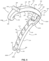
- FIGS. 5-8 illustrate a second exemplary embodiment of a surgical clip 200 of the present invention.
- the surgical clip 200 has a proximal end portion 200A and a distal end portion 200B.
- the surgical clip 200 further includes a first leg member 202 having a proximal end portion 202A and a distal end portion 202B, and a second leg member 204 having a proximal end portion 204A and a distal end portion 204B.
- the proximal end portions 202A, 204A of the first and second leg members 202, 204 may be releasably connected at a hinge portion 206.
- the surgical clip 200 may have elements and/or aspects similar to the surgical clip 100, and may be similarly represented in FIGS. 5-8 . For the sake of brevity, the elements and/or aspects similar to those of the surgical clip 100 may not be discussed with reference to the surgical clip 200.
- the first and second leg members 202, 204 include surfaces having curved portions.
- the first leg member 202 includes a first inner surface 208 and a first outer surface 210
- the second leg member 204 includes a second inner surface 212 and a second outer surface 214.
- the first inner surface 208 has a concave configuration
- the first outer surface 210 may have a convex configuration.
- the second inner surface 212 has a convex configuration
- the second outer surface 214 may have a concave configuration.
- the first and second inner surfaces 208, 212 may be approximated in a closed configuration, and may be resiliently flexible along its length to distribute pressure over a width of the tissue as the tissue is ligated.
- the first and second inner surfaces 208, 212 may each have a continuous curvature between proximal and distal end portions to provide a favorable compression of tissue.
- the surgical clip 200 also includes two latching or locking mechanisms.
- the first leg member 202 may transition to a hook section 226 at its distal end portion 202B
- the second leg member 204 may transition to a pointed tip portion 228 at its distal end 204B.
- a distal end portion of the hook section 226 may curve inwardly and point generally toward the concave inner surface 216 of the hinge portion 206.
- the hook section 226 may have one or more transverse beveled surfaces 230 and a concave inner surface which merges with the first inner surface 208 to define a recess 232.
- the tip portion 228 may be V-shaped defining a slot configured to receive the beveled surfaces 230, as the hook section 226 deflects around the tip portion 228.
- the hook section 226 and the tip portion 228 may engage to form a first latching or locking mechanism.
- the recess 232 may engage with the tip portion 228 in the course of compressing the surgical clip 200 into the closed configuration (e.g., FIGS. 7-8 ) that may be secured position around a vessel or other tissue.
- the first and second leg members 202, 204 of the surgical clip 200 may be separable.
- the proximal end portions 202A, 204A of the first and second leg members 202, 204 may be separable at the hinge portion 206.
- the proximal end portion 202A of the first leg member 202 includes a barrel 264 formed from a proximal elongate member 266 and a distal elongate member 268.
- the proximal elongate member 266 may form at least a portion of the proximal end portion 202A of the first leg member 202.
- One or more of the elongate members 266, 268 of the barrel 264 is arcuate in opposite direction and spaced to form a slot 270 with an opening 272.
- the slot 270 may have a recessed concave portion with a substantially circular cross-section.
- the slot 270 and the opening 272 may extend the entire width of the first leg member 202, and may be sized to receive a hinge pin 274 on the proximal end portion 204A of the second leg member 204.
- the hinge pin 274 may include side surfaces 276 on opposite sides of the hinge pin 274.
- the side surfaces 276 may be substantially flat and allow the surgical clip 200 to be selectively assembled or disassembled when the hinge pin 274 is passed through the opening 272 at a predetermined angle. In other words, the hinge pin 274 may not fit into the opening 272 at any angle other than the predetermined angle. In the example as depicted in FIG. 5 , the side surfaces 276 may be disposed at an angle between about 90° and 135° relative to a longitudinal axis of the second leg member 204, such that assembly or disassembly of the surgical clip 200 may be performed when the opening 272 of the second leg member 204 is disposed at the angle relative to the hinge pin 274 of the second leg member 204.
- the selective assembly/disassembly of the surgical clip 200 may prevent disassembly during the ordinary course of use of the surgical clip 200.
- the side surfaces 276 may be substantially offset of the opening 272 ( e.g. , by at least about 90°) when the surgical clip 200 in the closed configuration to prevent the surgical clip 200 from disassembling.
- the surgical clip 200 may be assembled in situ , for example, immediately prior to compression of the surgical clip 200 onto tissue.
- the surgical clip 200 may be assembled by the barrel 264 of the first leg member 202 being received in a channel 278 of the second leg member 204.
- the channel 278 may be defined by the hinge pin 274, a proximal surface 280 of the second leg member 204, and first and second leg extension members 282 extending between main body of the second leg member 204 and the hinge pin 274.
- the channel 278 may allow passage of the distal elongate member 268 to transition the surgical clip 200 from the open configuration ( e.g. , FIG. 5 ) to the closed configuration ( e.g., FIGS. 7-8 ).
- the interaction of the distal elongate member 268 and the channel 278 provides a second latching or locking mechanism to secure the surgical clip 200 in the closed configuration.
- the distal elongate member 268 includes a tooth or protrusion 284 that engages an undercut 286 on the proximal surface 280 of the second leg member 204.
- One or more of the protrusion 284 and the undercut 286 may deflect as the protrusion 284 passes through the channel 278, and the protrusion 284 and the undercut 286 may then provide a latching, interlocking, and/or interference fit to prevent the surgical clip 200 from pivoting to the open configuration ( e.g. , FIGS. 5-6 ) from the closed configuration ( e.g. , FIGS. 7-8 ).
- the protrusion 284 is spaced from the undercut 286 when the surgical clip 200 is in the closed configuration and in the absence of tissue.
- the first locking mechanism may be engaged in the closed configuration, while the second locking mechanism may not be engaged.
- the spacing between the protrusion 284 and undercut 286 in the closed configuration may allow flexibility of the surgical clip 200 along its length to accommodate different thicknesses of tissue and to distribute pressure over a width of the tissue as it is ligated.
- the second locking mechanism may also reinforce the first locking mechanism
- the second locking mechanism may prevent the surgical clip 200 from opening when the surgical clip 200 (e.g., the first locking mechanism) wears and/or breaks, such as when uneven absorption and/or degradation of the surgical clip 200 causes the first locking mechanism to disengage.
- the elongated member 268 may include only a single protrusion 284, without any type of ratcheting or tightening mechanism
- the surgical clip 200 may include a first plurality of teeth 234 protruding on the first inner surface 208, and a second plurality of teeth 236 protruding on the second inner surface 212.
- the teeth 234, 236 may maximize security of compressed tissue and minimize migration.
- the teeth 234, 236 may be angled toward the proximal end portion 202A of the surgical clip 200 in order to secure the tissue toward the hinge portion 206.
- the first and second plurality of teeth 234, 236 may include two or more staggered rows of teeth collectively extending the width of the inner surfaces 208, 212.
- the first plurality of teeth 234 may not engage the second plurality of teeth 236 in the closed configuration to increase the discrete contact points along the length of the surgical clip 200 and enhance security.
- one or more of the teeth 234, 236 may be omitted.
- the leg members 202, 204 may include one or more bosses along their length to engage a clip applier.
- the first leg member 202 may include cylindrical bosses 246, 248 protruding perpendicular to each of the opposed side surfaces 238, 240 adjacent to distal end portion 202B of first leg member 202 and immediately inward of hook section 226.
- the bosses 246, 248 may be cylindrical and project outwardly beyond the first outer surface 210 of first leg member 202.
- the bosses 246, 248 may also be coupled together by a bridge section 250.
- the second leg member 104 may also include bosses 252, 254 at the distal end portion 204B.
- the bosses 252, 254 may be cylindrical and protrude perpendicular to each of opposed side surfaces 242, 244 of second leg member 204, extending longitudinally forward beyond the point of tip portion 228.
- the surgical clip 200 may be designed to be compressed into a latched or locked configuration around the vessel through the use of an appropriate clip applier, such as described in U.S. Pat. No. 5,100,416 .
- FIGS. 9-11 illustrate a third exemplary embodiment of a surgical clip 300 of the present invention.
- the surgical clip 300 may has a proximal end portion 300A and a distal end portion 300B.
- the surgical clip 300 further includes a first leg member 302 having a proximal end portion 302A and a distal end portion 302B, and a second leg member 304 having a proximal end portion 304A and a distal end portion 304B.
- the proximal end portions 302A, 304A of the first and second leg members 302, 304 may be connected by a hinge portion 306.
- the surgical clip 300 may have elements similar to at least one of the surgical clips 100, 200, and may be similarly represented in FIGS. 9-11 . For the sake of brevity, the elements and/or aspects of the elements similar to those of the surgical clip 100, 200 may not be discussed with reference to the surgical clip 300.
- the first and second leg members 302, 304 include surfaces having curved portions.
- the first leg member 302 includes a first inner surface 208 and a first outer surface 310
- the second leg member 304 includes a second inner surface 312 and a second outer surface 314.
- the first inner surface 308 has a concave configuration
- the first outer surface 310 may have a convex configuration
- the second inner surface 312 has a convex configuration
- the second outer surface 314 may have a concave configuration.
- the first and second inner surfaces 308, 312 may be approximated in a closed configuration, and may be resiliently flexible along its length to distribute pressure over a width of the tissue as the tissue is ligated.
- the first and second inner surfaces 308, 312 may each have a continuous curvature between proximal and distal end portions to provide a favorable compression of tissue.
- the hinge portion 306 may have a concave inner surface 316 and a convex outer surface 318.
- the concave inner surface 316 of hinge portion 306 may continuously join the first inner surface 308 of the first leg member 302 and the second inner surface 312 of the second leg member 304.
- the convex outer surface 318 of the hinge portion 306 may join the first outer surface 310 of the first leg member 302 and the second outer surface 314 of the second leg member 304.
- the hinge portion 306 may also include a curved slot 320 located between the curved hinge surfaces 316, 318, and the curved slot 320 may be positioned closer to the concave inner surface 316 than to the convex outer surface 318.
- the curved slot 320 may extend completely through the hinge portion 306 from side to side and its opposite ends 322, 324 may extend into the proximal end portions 302A, 304A of the first and second leg members 302, 304, respectively.
- the curved slot 320 may provide added flexibility and resiliency to the hinge portion 306, but the concave inner surface 316 may prevent any portion of a clamped vessel from being trapped within the curved slot 320.
- the hinge portion 306 may be resilient and integral to the proximal end portions 302A, 304A of the first and second leg members 302, 304. For example, the hinge portion 306 may bias the surgical clip 300 into an open configuration.
- the surgical clip 300 includes two latching or locking mechanisms.
- the first leg member 302 may transition to a hook section 326 at its distal end portion 302B
- the second leg member 304 may transition to a pointed tip portion 328 at its distal end 304B.
- a distal end portion of the hook section 326 may curve inwardly and point generally toward the concave inner surface 316 of the hinge portion 306.
- the hook section 326 may have one or more transverse beveled surfaces 330 and a concave inner surface which merges with the first inner surface 308 to define a recess 332.
- the tip portion 328 may be V-shaped defining a slot configured to receive the beveled surfaces 330, as the hook section 326 deflects around the tip portion 328.
- the hook section 326 and the tip portion 328 may engage to form a first latching or locking mechanism.
- the recess 332 may engage with the tip portion 328 in the course of compressing the surgical clip 300 into the closed configuration (e.g., FIG. 11 ) that may be secured position around a vessel or other tissue.
- the surgical clip 300 also includes a second latching or locking mechanism.
- one or more elongate members 390 extend from the first leg member 302, from a length between the proximal end portion 302A and the distal end portion 302B.
- the one or more elongated members 390 may include first and second elongated members 390 extending from opposing sides 338, 340 of the first leg member 302, in an external or "out-board" configuration, and configured to receive the second leg member 304 therebetween.
- the elongate member(s) 390 may be positioned anywhere on the length of the first leg member 302.
- the elongate member(s) 390 may be positioned closer to the proximal end portion 302A than the distal end portion 302B (e.g., on the proximal half of the first leg member 302) in order to secure the proximal end portion 300A of the surgical clip 300. In some embodiments, the elongate member(s) 390 may be positioned closer to the proximal end portion 302A than a centerline of the first leg member 302 (e.g., on the proximal quarter of the first leg member 302) in order to distribute the latching force along the length of the surgical clip 300.
- the elongate member(s) 390 extend in an arcuate configuration from the first leg member 302 approximating the arcuate path of the second leg member 304 relative to the first leg member 302.
- FIGS. 8-11 illustrate the elongate member(s) 390 on the first leg member 302
- the surgical clip 300 may, additionally, include one or more elongated members 390 on the second leg member 304.
- the elongate member(s) 390 include a tooth or protrusion 392 configured to engage an outer surface 314 of the second leg member 304 to provide the second latching or locking mechanism
- the protrusion 392 is spaced from the outer surface 314 when the surgical clip 300 is in the closed configuration and in the absence of tissue ( e.g. , FIG. 11 ).
- the first locking mechanism may be engaged in the closed configuration, while the second locking mechanism may not be engaged.
- the spacing between the protrusion 392 and outer surface 314 in the closed configuration may allow flexibility of the surgical clip 300 along its length to accommodate different thicknesses of tissue and to distribute pressure over a width of the tissue as it is ligated.
- the second locking mechanism may also reinforce the first locking mechanism
- the second locking mechanism may prevent the surgical clip 300 from opening when the surgical clip 300 (e.g. , the first locking mechanism) wears and/or breaks, such as when uneven absorption and/or degradation of the surgical clip 300 causes the first locking mechanism to disengage.
- each of the elongate member(s) 390 may include only a single protrusion 392, without any type of ratcheting or tightening mechanism.
- the surgical clip 300 may include a first plurality of teeth 334 protruding on the first inner surface 308, and a second plurality of teeth 336 protruding on the second inner surface 312.
- the teeth 334, 336 may maximize security of compressed tissue and minimize migration.
- the teeth 334, 336 may be angled toward the proximal end portion 302A of the surgical clip 300 in order to secure the tissue toward the hinge portion 306.
- the first and second plurality of teeth 334, 336 may include two or more staggered rows of teeth collectively extending the width of the inner surfaces 308, 312.
- the first plurality of teeth 334 may not engage the second plurality of teeth 336 in the closed configuration to increase the discrete contact points along the length of the surgical clip 300 and enhance security.
- one or more of the teeth 334, 336 may be omitted.
- the leg members 302, 304 may include one or more bosses along their length to engage a clip applier.
- the first leg member 302 may include cylindrical bosses 346, 348 protruding perpendicular to each of the opposed side surfaces 338, 340 adjacent to distal end portion 302B of first leg member 302 and immediately inward of hook section 326.
- the bosses 346, 348 may be cylindrical and project outwardly beyond the first outer surface 310 of first leg member 302.
- the bosses 346, 348 may also be coupled together by a bridge section 350.
- the second leg member 304 may also include bosses 352, 354 at the distal end portion 304B.
- the bosses 352, 354 may be cylindrical and protrude perpendicular to each of opposed side surfaces 342, 344 of second leg member 304, extending longitudinally forward beyond the point of tip portion 328.
- the surgical clip 300 may be designed to be compressed into a latched or locked configuration around the vessel through the use of an appropriate clip applier, such as described in U.S. Pat. No. 5100416 .
- the surgical clips 100, 200, 300 may be made of any suitable size and may be applied to any number of tissues, such as blood vessels, lymph nodes, nerves, fallopian tubes, or cardiac tissue.
- the surgical clip 100, 200, 300 may be constructed from any suitable biocompatible material, such as certain metals and polymers.
- the surgical clip 100, 200, 300 may include absorbable and/or non-absorbable polymeric materials.
- Exemplary polymeric materials include homopolymers or co-polymers of one or more of polyacetal, polyethylene terephthalate (PET), polybutylene terephthalate (PBT), polyoxymethylene (POM), polymethyl methacrylate (PMMA), polylactic acid (PLA), polyglycolic acid (PGA), and other thermoplastic materials having similar properties that can be injection-molded, extruded or otherwise processed into like articles.
- the surgical clips 100, 200, 300 of the present invention are especially suitable for absorbable material that are weaker and degrade, sometimes at an uneven rate.
- the surgical clip 100, 300 may be a one-piece integral polymeric body to facilitate manufacturing. It is also contemplated that each of the leg members 202, 204 of the surgical clip 200 may be a one-piece integral polymeric body to facilitate manufacturing.
Claims (15)
- Chirurgische Klammer (100), die dazu konfiguriert ist, Gewebe abzubinden, wobei die chirurgische Klammer Folgendes umfasst:ein erstes Schenkelelement (102, 202, 302) und ein zweites Schenkelelement (104, 204, 304), wobei das erste Schenkelelement eine innere Oberfläche (108, 208, 308) mit einer konkaven Krümmung entlang ihrer Länge aufweist und das zweite Schenkelelement eine innere Oberfläche (112, 212, 312) mit einer konvexen Krümmung entlang ihrer Länge aufweist, wobei das erste und das zweite Schenkelelement dazu konfiguriert sind, sich zwischen einer offenen Konfiguration, in der die inneren Oberflächen voneinander beabstandet sind, und einer geschlossenen Konfiguration, in der die inneren Oberflächen aneinander angenähert sind, zu bewegen;ein erstes Verriegelungselement (126, 226, 326), das an einem distalen Endabschnitt (102B, 202B, 302B) des ersten Schenkelelements positioniert ist, und ein zweites Verriegelungselement (128, 228, 328), das an einem distalen Endabschnitt (104B, 204B, 304B) des zweiten Schenkelelements positioniert ist, wobei das erste und das zweite Verriegelungselement dazu konfiguriert sind, zu interagieren, um das erste und das zweite Schenkelelement in der geschlossenen Konfiguration zu fixieren; undein drittes Verriegelungselement (156, 268, 392), das zwischen einem proximalen Endabschnitt (102A, 202A, 302A) und dem distalen Endabschnitt (102B, 202B, 302B) des ersten Schenkelelements (102, 202, 302) positioniert ist, und ein viertes Verriegelungselement (158, 278, 314), das zwischen einem proximalen Endabschnitt (104A, 204A, 304A) und dem distalen Endabschnitt (104B, 204B, 304B) des zweiten Schenkelelements (104, 204, 304) positioniert ist, wobei das dritte und das vierte Verriegelungselement dazu konfiguriert sind, zu interagieren, um das erste und das zweite Schenkelelement in der geschlossenen Konfiguration zu fixieren, wobei das dritte Verriegelungselement ein langgestrecktes Element (156, 268, 390) umfasst, das sich von dem ersten Schenkelelement in einer bogenförmigen Konfiguration erstreckt und das einen Vorsprung (160, 284, 392) umfasst, der dazu konfiguriert ist, das vierte Verriegelungselement in Eingriff zu nehmen,dadurch gekennzeichnet, dass der Vorsprung in der geschlossenen Konfiguration und in Abwesenheit von Gewebe von dem vierten Verriegelungselement beabstandet ist.
- Chirurgische Klammer nach Anspruch 1, wobei das erste Verriegelungselement einen Haken (126, 226, 326) umfasst und das zweite Verriegelungselement eine Aussparung (132, 232, 332) umfasst, wobei der Haken dazu konfiguriert ist, um den distalen Endabschnitt des zweiten Schenkelelements ausgelenkt zu werden und in der Aussparung aufgenommen wird.
- Chirurgische Klammer nach mindestens einem der vorangehenden Ansprüche, wobei das vierte Verriegelungselement einen eine Hinterschneidung (162, 286) aufweisenden Durchgang (158, 278) umfasst, wobei der Durchgang dazu konfiguriert ist, das langgestreckte Element aufzunehmen, und die Hinterschneidung dazu konfiguriert ist, den Vorsprung in Eingriff zu nehmen, und der Vorsprung in der geschlossenen Konfiguration von der Hinterschneidung beabstandet ist.
- Chirurgische Klammer nach mindestens einem der vorangehenden Ansprüche, wobei das dritte Verriegelungselement einen einzigen Vorsprung ohne einen Rastmechanismus umfasst.
- Chirurgische Klammer nach Anspruch 3, wobei sich der Durchgang durch ein erstes Segment des zweiten Schenkelements erstreckt, wobei das erste Segment eine Breite aufweist, die größer als eine Breite eines zweiten Segments des zweiten Schenkelelements ist.
- Chirurgische Klammer nach Anspruch 5, wobei das zweite Segment des zweiten Schenkelelements dazu konfiguriert ist, Gewebe in Eingriff zu nehmen.
- Chirurgische Klammer nach mindestens einem der vorangehenden Ansprüche, wobei das dritte Verriegelungselement ein atraumatisches Ende umfasst.
- Chirurgische Klammer nach mindestens einem der vorangehenden Ansprüche, wobei das dritte Verriegelungselement auf einer proximalen Hälfte der inneren Oberfläche des ersten Schenkelelements positioniert ist.
- Chirurgische Klammer nach mindestens einem der vorangehenden Ansprüche, ferner umfassend einen Gelenkabschnitt (106, 206, 306), der die proximalen Endabschnitte des ersten und des zweiten Schenkelelements verbindet, wobei der Gelenkabschnitt dazu konfiguriert ist, das erste Schenkelelement relativ zu dem zweiten Schenkelelement zu schwenken, und das dritte Verriegelungselement einen Abschnitt des Gelenkabschnitts bildet.
- Chirurgische Klammer nach Anspruch 9, wobei der Gelenkabschnitt einen an dem proximalen Ende des ersten Schenkelelements positionierten Hohlzylinder (264) umfasst, der dazu konfiguriert ist, sich um einen an dem proximalen Endabschnitt des zweiten Schenkelelements positionierten Gelenkzapfen (274) zu drehen, wobei der Hohlzylinder das dritte Verriegelungselement umfasst, wobei das dritte Verriegelungselement den Vorsprung (284) an dem Hohlzylinder umfasst und es sich bei dem vierten Verriegelungselement um eine Hinterschneidung (286) in dem proximalen Endabschnitt des zweiten Schenkelelements handelt und der Vorsprung in der geschlossenen Konfiguration von der Hinterschneidung beabstandet ist.
- Chirurgische Klammer nach Anspruch 10, wobei der Hohlzylinder eine Öffnung (272) zwischen einem Ende des dritten Verriegelungselements und einem proximalen Endabschnitt des ersten Schenkelelements umfasst und der Gelenkzapfen mindestens eine flache Oberfläche (276) umfasst,
wobei die Öffnung im Wesentlichen von der mindestens einen flachen Oberfläche versetzt ist, wenn sich die chirurgische Klammer in der geschlossenen Konfiguration befindet, und die mindestens eine flache Oberfläche unter einem Winkel von etwa 135° von einer Längsachse des zweiten Schenkelelements angeordnet ist. - Chirurgische Klammer nach mindestens einem der vorangehenden Ansprüche, ferner umfassend einen runden Vorsprung (146, 148, 152, 154, 246, 248, 252, 254, 346, 348, 352, 354), der an dem distalen Endabschnitt des ersten und/oder des zweiten Schenkelelements positioniert ist.
- Chirurgische Klammer nach mindestens einem der vorangehenden Ansprüche, wobei die Klammer an absorbierbares Polymermaterial umfasst.
- Chirurgische Klammer nach mindestens einem der vorangehenden Ansprüche, wobei mindestens eine der inneren Oberfläche des ersten und des zweiten Schenkelelements eine Vielzahl von Zähnen (134, 136, 234, 236, 334, 336) umfasst, die in Richtung eines proximalen Endabschnitts der chirurgischen Klammer schräggestellt sind, und die Vielzahl von Zähnen in der geschlossenen Konfiguration distal des dritten Verriegelungselements positioniert ist.
- Chirurgische Klammer nach mindestens einem der vorangehenden Ansprüche, wobei das dritte Verriegelungselement ein erstes und ein zweites langgestrecktes Element (390) umfasst, die sich von gegenüberliegenden Seitenoberflächen (338, 340) des ersten Schenkelelements erstrecken, und das vierte Verriegelungselement eine äußere Oberfläche (314) des zweiten Schenkelelements umfasst und das erste und das zweite langgestreckte Element jeweils einen Vorsprung (392) umfassen, der dazu konfiguriert ist, die äußere Oberfläche des zweiten Schenkelelements in Eingriff zu nehmen.
Applications Claiming Priority (2)
| Application Number | Priority Date | Filing Date | Title |
|---|---|---|---|
| US201762585795P | 2017-11-14 | 2017-11-14 | |
| PCT/US2018/060946 WO2019099462A1 (en) | 2017-11-14 | 2018-11-14 | Surgical clip |
Publications (2)
| Publication Number | Publication Date |
|---|---|
| EP3709900A1 EP3709900A1 (de) | 2020-09-23 |
| EP3709900B1 true EP3709900B1 (de) | 2024-04-10 |
Family
ID=64572548
Family Applications (1)
| Application Number | Title | Priority Date | Filing Date |
|---|---|---|---|
| EP18812518.1A Active EP3709900B1 (de) | 2017-11-14 | 2018-11-14 | Chirurgische klammer |
Country Status (7)
| Country | Link |
|---|---|
| US (2) | US11648014B2 (de) |
| EP (1) | EP3709900B1 (de) |
| JP (2) | JP7174048B2 (de) |
| KR (2) | KR20230003454A (de) |
| CN (2) | CN111432737B (de) |
| AU (2) | AU2018369752B2 (de) |
| WO (1) | WO2019099462A1 (de) |
Families Citing this family (8)
| Publication number | Priority date | Publication date | Assignee | Title |
|---|---|---|---|---|
| JP7068355B2 (ja) | 2017-06-22 | 2022-05-16 | テレフレックス メディカル インコーポレイテッド | 外科用クリップ |
| US11648014B2 (en) * | 2017-11-14 | 2023-05-16 | Teleflex Medical Incorporated | Surgical clip |
| US11707282B2 (en) * | 2019-07-02 | 2023-07-25 | Covidien Lp | Multi-piece ligation clip |
| US20210137524A1 (en) * | 2019-11-13 | 2021-05-13 | Covidien Lp | Multi-Part Ligation Clip |
| US11696764B2 (en) * | 2020-01-31 | 2023-07-11 | Covidien Lp | Ligation clip with controlled tissue compression |
| WO2021254151A1 (zh) * | 2020-06-17 | 2021-12-23 | 苏州英途康医疗科技有限公司 | 一种组织夹及止血装置 |
| US11246600B1 (en) * | 2020-08-13 | 2022-02-15 | Geoff Brown | Surgical ligation clip with advanced incising means and bifurcated guide track |
| CN113040856B (zh) * | 2021-04-27 | 2022-08-09 | 浙江微度医疗器械有限公司 | 增强型结扎夹 |
Family Cites Families (247)
| Publication number | Priority date | Publication date | Assignee | Title |
|---|---|---|---|---|
| US1728322A (en) | 1928-02-22 | 1929-09-17 | Badrian Max | Device for elastically clamping off the male urethra |
| US2384697A (en) | 1944-10-18 | 1945-09-11 | Riccardi Peter | Umbilical clip |
| US2498372A (en) | 1946-10-04 | 1950-02-21 | Jr Frederick F Kortlucke | Clamping device |
| US2635238A (en) | 1949-07-11 | 1953-04-21 | Garland Mather | Apparatus for clamping umbilical cords and the like |
| US2626608A (en) | 1949-12-08 | 1953-01-27 | Garland Mather | Clamp for umbilical cords and the like |
| US2598901A (en) | 1950-03-10 | 1952-06-03 | Garland Mather | Clamp for constricting flexible tubular elements and the like |
| US3171184A (en) * | 1962-10-30 | 1965-03-02 | Posse Nils Lage Wilhelm | Clamp |
| US3503397A (en) | 1967-09-21 | 1970-03-31 | American Hospital Supply Corp | Atraumatic surgical clamp |
| US3766925A (en) | 1971-05-25 | 1973-10-23 | Eljay Hospital Prod Corp | Surgical clamp with cam-action lever |
| US3867944A (en) | 1972-10-27 | 1975-02-25 | Wood Ernest C | Hemostatic clip and applicator therefor |
| US3924629A (en) | 1973-01-20 | 1975-12-09 | Taichiro Akiyama | Method for closing a cut end of a blood vessel |
| US3874042A (en) | 1973-01-22 | 1975-04-01 | Biospectrum Inc | Clamp for thin walled tubing |
| US3825012A (en) | 1973-04-13 | 1974-07-23 | H Nicoll | Reusable umbilical cord clamp for veterinary use |
| US4340061A (en) | 1977-10-25 | 1982-07-20 | Mayfield Education And Research Fund | Aneurysm clip |
| US4337774A (en) | 1978-06-14 | 1982-07-06 | Metatech Corporation | Micro surgical clip |
| US4212303A (en) | 1978-07-17 | 1980-07-15 | Hollister Incorporated | Umbilical cord clamp |
| US4390019A (en) | 1979-02-28 | 1983-06-28 | Leveen Harry H | Blood vessel clamp |
| US4434795A (en) | 1979-06-18 | 1984-03-06 | Ethicon, Inc. | Instrument for applying ligating clips |
| US4527562A (en) | 1979-06-18 | 1985-07-09 | Ethicon, Inc. | Non-metallic, bio-compatible hemostatic clips |
| CA1157335A (en) | 1979-06-18 | 1983-11-22 | Namassivaya Doddi | Plastic ligating clips |
| US4418694A (en) | 1979-06-18 | 1983-12-06 | Ethicon, Inc. | Non-metallic, bio-compatible hemostatic clips |
| US4638804A (en) | 1980-02-25 | 1987-01-27 | Ethicon, Inc. | Double-latched non-metallic, bio-compatible hemostatic clip |
| MX151148A (es) | 1980-02-25 | 1984-10-04 | Johnson & Johnson | Mejoras en pinzas hemostaticas |
| US4345600A (en) | 1980-08-04 | 1982-08-24 | Senco Products, Inc. | Purse-stringer |
| US4346869A (en) | 1981-03-12 | 1982-08-31 | Macneill Robert L | Tube clamp |
| US4449531A (en) | 1981-08-27 | 1984-05-22 | Ethicon, Inc. | Non-metallic, bio-compatible hemostatic clips with interlocking latch means |
| US4550729A (en) | 1981-08-27 | 1985-11-05 | Ethicon, Inc. | Non-metallic, bio-compatible hemostatic clips with interlocking latch means |
| US4476865A (en) | 1982-02-12 | 1984-10-16 | Ethicon, Inc. | Non-metallic, bio-compatible hemostatic clips |
| US4450840A (en) | 1982-02-26 | 1984-05-29 | Ethicon, Inc. | Ligating clip with flanged base having a recessed engaging face |
| US4487205A (en) | 1982-04-26 | 1984-12-11 | Ethicon, Inc. | Non-metallic, bio-compatible hemostatic clips |
| US4458682A (en) | 1982-08-02 | 1984-07-10 | Ethicon, Inc. | Non-metallic, bio-compatible hemostatic clips (ring lock clips) |
| US4519392A (en) | 1982-10-12 | 1985-05-28 | Lingua Robert W | Hemostasing muscle clips for needleless surgery |
| US4558699A (en) | 1983-01-03 | 1985-12-17 | Bashour Samuel B | Method of and apparatus for restricting the passage of food through the stomach |
| JPS59168848A (ja) | 1983-03-11 | 1984-09-22 | エチコン・インコ−ポレ−テツド | 非金属製の生物に適合性の無菌の外科装置 |
| US4579118A (en) | 1983-06-01 | 1986-04-01 | Ethicon, Inc. | Hemostatic clip with penetration means |
| US5127915A (en) | 1984-10-29 | 1992-07-07 | Mattson Philip D | Surgical instrument for severing and clamping an umbilical cord |
| US4589626A (en) | 1985-03-13 | 1986-05-20 | Bioresearch Inc. | Hose clamp |
| US4588160A (en) | 1985-03-27 | 1986-05-13 | Sherwood Medical Company | Tube clamping device |
| US4673161A (en) | 1985-03-27 | 1987-06-16 | Sherwood Medical Company | Tube clamping device |
| JPH0657218B2 (ja) | 1985-05-10 | 1994-08-03 | エチコン・インコ−ポレ−テツド | 結紮クリツプ及びクリツプ適用器具 |
| US5047038A (en) | 1985-07-01 | 1991-09-10 | Edward Weck Incorporated | Automatic hemostatic clip applier |
| US4712549A (en) | 1985-07-01 | 1987-12-15 | Edward Weck & Co. | Automatic hemostatic clip applier |
| US4807622A (en) | 1985-09-20 | 1989-02-28 | Kato Hatsujo Kaisha, Ltd. | Tube cutting and separating implement for conduit of blood or the like |
| US4667671A (en) | 1985-11-15 | 1987-05-26 | Danzig Fred G | Apparatus for ligating blood vessels, nerves and other anatomical structures |
| US4716886A (en) | 1986-05-01 | 1988-01-05 | Norman Schulman | Umbilical cord clamp and cutters |
| US4938215A (en) | 1986-05-01 | 1990-07-03 | Norman M. Schulman | Umbilical cord clamp and cutters |
| US4726372A (en) | 1986-09-19 | 1988-02-23 | Metatech Corporation | Hemostatic clip |
| US4844066A (en) | 1987-04-06 | 1989-07-04 | Richard-Allan Medical Industries, Inc. | Surgical clip |
| US4822348A (en) * | 1987-05-13 | 1989-04-18 | Donn Casey | Surgical clips |
| US5366459A (en) | 1987-05-14 | 1994-11-22 | Inbae Yoon | Surgical clip and clip application procedures |
| US4834096A (en) | 1987-10-26 | 1989-05-30 | Edward Weck Incorporated | Plastic ligating clips |
| GB2212201B (en) * | 1987-11-10 | 1992-06-03 | Donn Casey | Surgical clip |
| US4870965A (en) | 1988-03-04 | 1989-10-03 | Jahanger Mohammed S | Umbilical cord cutting and clamping device |
| US4955897A (en) | 1988-08-22 | 1990-09-11 | Ship Arthur G | Tissue forceps |
| US4942886A (en) | 1989-02-22 | 1990-07-24 | Timmons John W | External incontinency device |
| US5062846A (en) | 1989-03-28 | 1991-11-05 | Edward Weck Incorporated | Penetrating plastic ligating clip |
| US4976722A (en) | 1989-05-22 | 1990-12-11 | Ethicon, Inc. | Surgical hemostatic clips |
| US4938765A (en) | 1989-06-22 | 1990-07-03 | Life Centers, Inc. | Surgical silicon loops |
| US5104395A (en) | 1989-07-03 | 1992-04-14 | Edward Weck Incorporated | Automatic hemostatic clip applicator |
| US4950275A (en) | 1989-07-19 | 1990-08-21 | Cyanamid Italia S.P.A. | Bowel-anastomosis-ring holder pincers |
| US4936447A (en) | 1989-09-26 | 1990-06-26 | Horizon Surgical Inc. | Hemostatic clip holder |
| US4972949A (en) | 1989-09-26 | 1990-11-27 | Horizon Surgical, Inc. | Hemostatic clip holder for small clips |
| US5100416A (en) | 1989-10-17 | 1992-03-31 | Edward Weck Incorporated | Ligating clip applying instrument |
| US5009657A (en) | 1989-12-14 | 1991-04-23 | Mohammed S. Jahanger | Umbilical cord cutting and clamping device |
| US5222961A (en) | 1989-12-26 | 1993-06-29 | Naomi Nakao | Endoscopic stapling device and related staple |
| US4961499A (en) | 1990-01-04 | 1990-10-09 | Pilling Co. | Hemostatic clip cartridge |
| US5078731A (en) | 1990-06-05 | 1992-01-07 | Hayhurst John O | Suture clip |
| US5026382A (en) | 1990-08-27 | 1991-06-25 | Horizon Surgical, Inc. | Hemostatic clip |
| US5201416A (en) | 1990-10-22 | 1993-04-13 | Edward Weck Incorporated | Hemostatic clip cartridge |
| US5046611A (en) | 1990-10-22 | 1991-09-10 | Edward Weck Incorporated | Hemostatic clip cartridge |
| US5366458A (en) | 1990-12-13 | 1994-11-22 | United States Surgical Corporation | Latchless surgical clip |
| USRE36720E (en) | 1990-12-13 | 2000-05-30 | United States Surgical Corporation | Apparatus and method for applying latchless surgical clips |
| US5171252A (en) | 1991-02-05 | 1992-12-15 | Friedland Thomas W | Surgical fastening clip formed of a shape memory alloy, a method of making such a clip and a method of using such a clip |
| US5171253A (en) | 1991-03-22 | 1992-12-15 | Klieman Charles H | Velcro-like closure system with absorbable suture materials for absorbable hemostatic clips and surgical strips |
| US5112343A (en) | 1991-04-05 | 1992-05-12 | Edward Weck Incorporated | Endoscopic clip appliers |
| US5160339A (en) | 1991-06-18 | 1992-11-03 | Ethicon, Inc. | Endoscopic suture clip |
| US5242456A (en) | 1991-11-21 | 1993-09-07 | Kensey Nash Corporation | Apparatus and methods for clamping tissue and reflecting the same |
| US5259405A (en) | 1992-01-29 | 1993-11-09 | Hua Chou Kuo | Structure of a barette |
| US5171251A (en) | 1992-03-02 | 1992-12-15 | Ethicon, Inc. | Surgical clip having hole therein and method of anchoring suture |
| CA2094463A1 (en) | 1992-04-28 | 1993-10-29 | Claude Vidal | Vessel clips |
| US5279416A (en) | 1992-06-05 | 1994-01-18 | Edward Weck Incorporated | Ligating device cartridge with separable retainer |
| US5234449A (en) | 1992-07-16 | 1993-08-10 | Ethicon, Inc. | Suture clip with reduced hinge mass |
| US5330442A (en) | 1992-10-09 | 1994-07-19 | United States Surgical Corporation | Suture retaining clip |
| US5330487A (en) | 1992-12-17 | 1994-07-19 | Tfi Acquistion Corp. | Drive mechanism for surgical instruments |
| WO1994015535A1 (en) | 1993-01-07 | 1994-07-21 | Hayhurst, John, O. | Clip for suture |
| CA2120828C (en) | 1993-04-16 | 1999-11-02 | Paul J. Phillips | Surgical hemostatic clip |
| US5549621A (en) | 1993-05-14 | 1996-08-27 | Byron C. Sutherland | Apparatus and method for performing vertical banded gastroplasty |
| DK110193A (da) | 1993-09-30 | 1995-03-31 | Per Baunsgaard | Klemmeanordning |
| US5462555A (en) | 1993-12-30 | 1995-10-31 | United States Surgical Corporation | Umbilical cord clip and applicator |
| GB9400739D0 (en) | 1994-01-15 | 1994-03-16 | Femcare Ltd | Medical clip |
| US5501693A (en) | 1994-07-06 | 1996-03-26 | United States Surgical Corporation | Surgical hemostatic clip |
| US5487746A (en) | 1994-11-23 | 1996-01-30 | Yu; George W. | Surgical clip having a longitudinal opening through which clamped tissue protrudes |
| US5695505A (en) | 1995-03-09 | 1997-12-09 | Yoon; Inbae | Multifunctional spring clips and cartridges and applicators therefor |
| US5667516A (en) | 1995-05-01 | 1997-09-16 | Allen; Sean A. | Mechanism for cutting an umbilical cord |
| US5908430A (en) | 1995-06-07 | 1999-06-01 | Appleby; Timothy | Easy loading hemostatic clip and cartridge |
| US5676676A (en) | 1995-08-30 | 1997-10-14 | Porter; Wayne | Ligating clip having ramp-shaped vessel-clamping members |
| US5713912A (en) | 1995-08-30 | 1998-02-03 | Stress Management, Inc. | Ligating clip having ramp-shaped vessel clamping members and tool for applying same |
| US5810853A (en) | 1996-01-16 | 1998-09-22 | Yoon; Inbae | Knotting element for use in suturing anatomical tissue and methods therefor |
| US6015417A (en) | 1996-01-25 | 2000-01-18 | Reynolds, Jr.; Walker | Surgical fastener |
| US5846255A (en) | 1996-01-31 | 1998-12-08 | Casey Medical Products Limited | Surgical clip |
| US5925052A (en) | 1996-06-26 | 1999-07-20 | Simmons; Paul L. | Umbilical surgical scissors |
| US5722982A (en) | 1996-09-26 | 1998-03-03 | University Technology Corporation | Strabismus surgery apparatus and method |
| US5713911A (en) | 1996-10-03 | 1998-02-03 | United States Surgical Corporation | Surgical clip |
| US20030236537A1 (en) | 1999-08-09 | 2003-12-25 | Applied Medical Resources Corporation | Surgical instruments with improved traction |
| US5921991A (en) * | 1997-10-23 | 1999-07-13 | Biomax Technologies Inc. | Multi-colored umbilical cord clamp |
| US6007552A (en) | 1997-12-18 | 1999-12-28 | Minumys | Vascular clamps and surgical retractors with directional filaments for tissue engagement |
| US6131576A (en) | 1998-03-23 | 2000-10-17 | Davis; Paul K. | Male incontinence clamp, kit and method of use |
| US5997548A (en) | 1998-07-22 | 1999-12-07 | Jahanger; Mohammed S. | Umbilical cord cutting and clamping device |
| US6099539A (en) | 1998-07-27 | 2000-08-08 | Thomas J. Fogarty | Surgical clamp pad with interdigitating teeth |
| DE19858581C2 (de) | 1998-12-18 | 2001-03-08 | Aesculap Ag & Co Kg | Gefäßclip |
| US6210419B1 (en) * | 1998-12-18 | 2001-04-03 | Aesculap Ag & Co. Kg | Surgical clip |
| US6217590B1 (en) | 1999-01-22 | 2001-04-17 | Scion International, Inc. | Surgical instrument for applying multiple staples and cutting blood vessels and organic structures and method therefor |
| GB2353710A (en) | 1999-08-06 | 2001-03-07 | Henleys Medical Supplies Ltd | Umbilical cord clamp |
| US6273903B1 (en) | 1999-11-08 | 2001-08-14 | Peter J. Wilk | Endoscopic stapling device and related staple |
| IL132913A (en) | 1999-11-14 | 2004-09-27 | Porat Michael | Device and method for clamping and cutting a flexible deformable tube |
| GB9927040D0 (en) | 1999-11-17 | 2000-01-12 | Femcare Ltd | Medical clips |
| US6695854B1 (en) | 1999-11-29 | 2004-02-24 | General Surgical Innovations, Inc. | Blood vessel clip and applicator |
| US7963964B2 (en) | 2000-02-10 | 2011-06-21 | Santilli Albert N | Surgical clamp assembly with electrodes |
| US6610074B2 (en) | 2000-02-10 | 2003-08-26 | Albert N. Santilli | Aorta cross clamp assembly |
| US6305387B1 (en) | 2000-03-14 | 2001-10-23 | Becky K. Atchison | Hair styling tool |
| US6419682B1 (en) | 2000-03-24 | 2002-07-16 | Timothy Appleby | Hemostatic clip cartridge |
| US6391035B1 (en) | 2000-03-24 | 2002-05-21 | Timothy Appleby | Hemostatic clip removal instrument |
| US6485503B2 (en) | 2000-05-19 | 2002-11-26 | Coapt Systems, Inc. | Multi-point tissue tension distribution device, a brow and face lift variation, and a method of tissue approximation using the device |
| US6349727B1 (en) | 2000-05-25 | 2002-02-26 | Pos-T-Vac, Inc. | Penile clamp for inhibiting incontinence |
| US6348057B1 (en) | 2000-08-18 | 2002-02-19 | Kencap Ltd. | Umbilical cord clamp and cutter |
| US6719766B1 (en) | 2000-08-24 | 2004-04-13 | Novare Surgical Systems, Inc. | Surgical clamp pads having surface overlay |
| US7232445B2 (en) | 2000-12-06 | 2007-06-19 | Id, Llc | Apparatus for the endoluminal treatment of gastroesophageal reflux disease (GERD) |
| US6981505B2 (en) | 2001-02-13 | 2006-01-03 | Krause William R | Urological device for the incontinent male |
| JP2002345828A (ja) | 2001-05-23 | 2002-12-03 | Asahi Optical Co Ltd | 内視鏡用クリップ装置 |
| US6824547B2 (en) | 2001-07-13 | 2004-11-30 | Pilling Weck Incorporated | Endoscopic clip applier and method |
| AUPR668901A0 (en) | 2001-07-31 | 2001-08-23 | Research Surgical Pty Ltd | Surgical clamps |
| US7338503B2 (en) | 2002-08-08 | 2008-03-04 | Interrad Medical, Inc. | Non-invasive surgical ligation clip system and method of using |
| US6638282B2 (en) | 2001-10-16 | 2003-10-28 | Cetus, Lc | Umbilical cord cutting and clamping device |
| US20050149069A1 (en) | 2001-12-04 | 2005-07-07 | Bertolero Arthur A. | Left atrial appendage devices and methods |
| WO2003063945A1 (en) | 2002-01-31 | 2003-08-07 | Baxter International Inc. | Irreversibly closable flow control clamp |
| US8262639B2 (en) | 2002-01-31 | 2012-09-11 | Fenwal, Inc. | Irreversible flow control clamp |
| US7131977B2 (en) | 2002-08-27 | 2006-11-07 | Pilling Weck Incorporated | Apparatus and method for removing a clip |
| US6880699B2 (en) | 2002-08-27 | 2005-04-19 | Pilling Weck Incorporated | Cartridge for holding asymmetric surgical clips |
| US7211091B2 (en) | 2002-08-27 | 2007-05-01 | Pilling Weck Incorporated | Fingertip-actuated surgical clip applier and related methods |
| US6863675B2 (en) | 2002-09-20 | 2005-03-08 | Pilling Weck Incorporated | Ligating clip with integral penetrating hook |
| WO2004043225A2 (en) | 2002-11-08 | 2004-05-27 | Maternus Partners, Ltd. | Umbilical cord clamp and cutter |
| US7211092B2 (en) | 2002-11-19 | 2007-05-01 | Pilling Weck Incorporated | Automated-feed surgical clip applier and related methods |
| US7052504B2 (en) | 2002-11-19 | 2006-05-30 | Teleflex Incorporated | Automated-feed surgical clip applier and related methods |
| US7107995B2 (en) | 2002-12-11 | 2006-09-19 | C&L Medical Supply Corporation | Urinary-control device |
| US6843253B2 (en) | 2002-12-11 | 2005-01-18 | C&L Medical Supply Corporation | Urinary-control device |
| WO2004058079A2 (en) | 2002-12-17 | 2004-07-15 | Applied Medical Resources Corporation | Surgical staple-clip and applier |
| GB0302098D0 (en) | 2003-01-29 | 2003-02-26 | Univ London | Improvements in and relating to surgical clips |
| GB0305976D0 (en) | 2003-03-14 | 2003-04-23 | Wild Andrew M | Surgical clip |
| US7316696B2 (en) | 2004-01-22 | 2008-01-08 | Teleflex Medical Incorporated | Ligating clip with integral interlocking latch mechanism |
| US7326223B2 (en) | 2004-01-22 | 2008-02-05 | Teleflex Medical Incorporated | Ligating clip with integral cutting guide |
| US20050165429A1 (en) | 2004-01-23 | 2005-07-28 | Peter Douglas | Surgical clamp possessing a combined parallel and scissor style clamp head |
| US20050165423A1 (en) | 2004-01-23 | 2005-07-28 | Pilling Weck Incorporated | Ligating clip with integral tissue-securing mechanism |
| US7001412B2 (en) * | 2004-01-28 | 2006-02-21 | Pilling Weck Incorporated | Surgical clip with integral suture-securing mechanism |
| US7585304B2 (en) | 2004-02-02 | 2009-09-08 | Teleflex Medical Incorporated | Endoscopic clip applying apparatus with improved aperture for clip release and related method |
| US7645285B2 (en) | 2004-05-26 | 2010-01-12 | Idx Medical, Ltd | Apparatus and methods for occluding a hollow anatomical structure |
| US20050273122A1 (en) | 2004-06-02 | 2005-12-08 | Microline, Inc. | Clip with enhanced gripping arrangement |
| BRMU8401529U (pt) | 2004-07-02 | 2006-02-21 | Milton Tatsuo Tanaka | clip cirúrgico curvo laparoscópico |
| CA2604216A1 (en) | 2005-03-24 | 2006-09-28 | Teleflex Medical Incorporated | Reduced closure force ligating clip |
| US20060217749A1 (en) | 2005-03-24 | 2006-09-28 | Pilling Weck Incorporated | Reduced closure force ligating clip |
| US20080045981A1 (en) | 2005-04-22 | 2008-02-21 | Ilya Margolin | Ligating clip and ligating clip applicator |
| US8945151B2 (en) | 2005-07-13 | 2015-02-03 | Atricure, Inc. | Surgical clip applicator and apparatus including the same |
| AU2006267056C1 (en) | 2005-07-14 | 2013-03-28 | Atricure, Inc. | Apparatus and methods for occluding a hollow anatomical structure |
| US20070083218A1 (en) | 2005-10-12 | 2007-04-12 | A Morris Steven | Coated ligating clip |
| US20070118161A1 (en) | 2005-11-22 | 2007-05-24 | Kennedy Daniel L | Non-snag polymer ligating clip |
| US9486225B2 (en) | 2005-12-22 | 2016-11-08 | Robert E. Michler | Exclusion of the left atrial appendage |
| US9480480B2 (en) | 2005-12-22 | 2016-11-01 | Albert N. Santilli | Vascular and intestinal occlusion |
| DE202006000329U1 (de) | 2006-01-11 | 2006-03-02 | Aesculap Ag & Co. Kg | Chirurgischer Ligaturclip |
| US20070173866A1 (en) | 2006-01-23 | 2007-07-26 | Tyco Healthcare Group, Lp | Surgical hemostatic clip |
| US7635374B2 (en) | 2006-03-09 | 2009-12-22 | Niti Surgical Solutions Ltd. | Endoscopic full thickness resection using surgical compression clips |
| US7892244B2 (en) | 2006-03-09 | 2011-02-22 | Niti Surgical Solutions Ltd. | Surgical compression clips |
| JP5148598B2 (ja) | 2006-05-03 | 2013-02-20 | ラプトール リッジ, エルエルシー | 組織閉鎖のシステムおよび方法 |
| US20080039879A1 (en) | 2006-08-09 | 2008-02-14 | Chin Albert K | Devices and methods for atrial appendage exclusion |
| US20080103512A1 (en) | 2006-10-23 | 2008-05-01 | G&L Consulting, Llc | Clamping system and method for fusing vertebral elements in a spine |
| US20080208324A1 (en) | 2007-02-23 | 2008-08-28 | Glithero Jason I | Method and apparatus for occluding an anatomical structure |
| US20080287976A1 (en) | 2007-05-14 | 2008-11-20 | Weaner Lauren S | Gastric band with engagement member |
| US8118826B2 (en) | 2007-09-27 | 2012-02-21 | Swan Valley Medical, Incorporated | Method of performing a suprapubic transurethral cystostomy and associated procedures and apparatus therefor |
| US9445820B2 (en) | 2007-12-31 | 2016-09-20 | Teleflex Medical Incorporated | Ligation clip with flexible clamping feature |
| US8366726B2 (en) | 2008-03-21 | 2013-02-05 | Gyrx Llc | Vessel occlusion clip and application thereof |
| US20100114131A1 (en) | 2008-11-05 | 2010-05-06 | Adam Rotunda | Skin tag removal system |
| DE102008057213A1 (de) | 2008-11-06 | 2010-05-12 | Aesculap Ag | Medizintechnisches Produkt, ein chirurgisches Kit sowie ein Herstellungsverfahren für das medizintechnische Produkt |
| GB2465560A (en) | 2008-11-19 | 2010-05-26 | Frank Vinzenz Benedikt | Absorbable veterinary sterilisation clamp |
| US8690911B2 (en) | 2009-01-08 | 2014-04-08 | Coherex Medical, Inc. | Medical device for modification of left atrial appendage and related systems and methods |
| US20100211080A1 (en) * | 2009-02-13 | 2010-08-19 | Dean Trivisani | Umbiliguard |
| CN101507646B (zh) | 2009-03-26 | 2012-08-22 | 杭州康基医疗器械有限公司 | 一种血管夹模具 |
| US20100274268A1 (en) | 2009-04-24 | 2010-10-28 | Singh Errol O | Squeeze-to-set medical clamp |
| CN101543418B (zh) | 2009-04-30 | 2011-01-05 | 何定甫 | 单面脐带夹 |
| BRMU8901448U2 (pt) | 2009-07-23 | 2010-10-05 | Fernando Cesar Tomazzi Lissa | disposição construtiva aplicada a clipe cirúrgico |
| EP3069662B1 (de) | 2009-09-25 | 2020-09-02 | Boston Scientific Scimed, Inc. | Vorrichtungen zur annäherung von gewebe |
| US10136898B2 (en) | 2010-03-09 | 2018-11-27 | Teleflex Medical Incorporated | Narrow profile surgical ligation clip |
| US8858577B2 (en) | 2010-05-19 | 2014-10-14 | University Of Utah Research Foundation | Tissue stabilization system |
| US20110295291A1 (en) | 2010-05-28 | 2011-12-01 | Dean Trivisani | Novel Vascular Clamp |
| US10335157B2 (en) | 2010-10-02 | 2019-07-02 | Covidien Lp | Asymmetrical surgical clip with penetrating lock, non-slip clamping surface, severable hinge, hinge boss and pivoting applicator tip |
| RU2485908C2 (ru) | 2010-12-07 | 2013-06-27 | Компания с ограниченной ответственностью Глобитек 2000 | Способ создания гемостаза с возможностью восстановления кровотока в трубчатых эластичных структурах организма и устройства для его осуществления |
| CN102028517A (zh) | 2011-01-21 | 2011-04-27 | 常州市三联星海医疗器械制造有限公司 | 组织夹 |
| US9801638B2 (en) | 2011-03-21 | 2017-10-31 | The Administrator Of The Tulane Educational Fund | Multi-component detachable jaw tools and methods of using and making same |
| WO2012135530A1 (en) | 2011-03-29 | 2012-10-04 | Ocunetics, Inc. | Fasteners, deployment systems, and methods for ophthalmic tissue closure and fixation of ophthalmic prostheses and other uses |
| US9289209B2 (en) * | 2011-06-09 | 2016-03-22 | Covidien Lp | Surgical fastener applying apparatus |
| US9451959B2 (en) * | 2011-06-09 | 2016-09-27 | Covidien Lp | Surgical fastener applying apparatus |
| JP2014531246A (ja) * | 2011-09-14 | 2014-11-27 | テレフレックス メディカル インコーポレイテッドTeleflex Medical Incorporated | 細い外科用結紮クリップ |
| WO2013040378A1 (en) | 2011-09-15 | 2013-03-21 | Teleflex Medical Incorporated | Automatic surgical ligation clip applier |
| CN104039248A (zh) | 2011-09-15 | 2014-09-10 | 泰利福医疗公司 | 手动外科结扎夹钳施用器 |
| JP6754169B2 (ja) | 2011-10-20 | 2020-09-09 | テレフレックス ライフ サイエンシーズ アンリミテッド カンパニー | 結紮クリップ |
| US9084596B2 (en) | 2012-02-27 | 2015-07-21 | Cook Medical Technologies Llc | Suture clamp and gastrointestinal suture anchor set device using same |
| US20130226200A1 (en) | 2012-02-28 | 2013-08-29 | Boston Scientific Scimed, Inc. | Clip applier |
| US20130245653A1 (en) * | 2012-03-19 | 2013-09-19 | Craig Michael Litherland | Zero artifact vascular clip method and apparatus |
| US9282972B1 (en) | 2012-10-14 | 2016-03-15 | Innovative Urololy, Llc | Surgical clips with penetrating locking mechanism and non-slip clamping surfaces |
| US9220507B1 (en) | 2012-10-14 | 2015-12-29 | Manoj B. Patel | Tissue spreading vascular clips with locking mechanism and non-slip clamping surfaces |
| US20140018832A1 (en) | 2013-09-13 | 2014-01-16 | Ethicon Endo-Surgery, Inc. | Method For Applying A Surgical Clip Having A Compliant Portion |
| EP3065646A1 (de) * | 2013-11-04 | 2016-09-14 | Covidien LP | Vorrichtung zum anbringen eines chirurgischen befestigungselements |
| US9433493B2 (en) | 2013-11-04 | 2016-09-06 | Biomet Sports Medicine, Llc | Tissue contacting member |
| CN103919589A (zh) | 2014-03-10 | 2014-07-16 | 浙江微度医疗器械有限公司 | 一种防脱落的止血夹 |
| US10125906B2 (en) * | 2014-08-21 | 2018-11-13 | Nordson Corporation | Reusable clamp with latch release arm for connecting conduit sections and associated methods |
| JP6463850B2 (ja) | 2014-12-12 | 2019-02-06 | アトリキュア インクAtricure Inc. | 閉塞クリップ |
| KR102365594B1 (ko) * | 2015-03-26 | 2022-02-22 | 주식회사 메타바이오메드 | 외과용 클립 |
| EP3310270A4 (de) | 2015-06-16 | 2019-04-10 | Nanova Biomaterials, Inc. | Chirurgische antimigrationsligaturklammer |
| CN105054989B (zh) | 2015-07-03 | 2017-03-22 | 桐庐洲济医疗器械有限公司 | 一次性血管夹 |
| US10384049B2 (en) | 2015-07-07 | 2019-08-20 | Halkey-Roberts Corporation | Tubing clamp |
| US10327762B2 (en) | 2015-07-17 | 2019-06-25 | Suturegard Medical, Inc. | Suture locks |
| WO2017017587A2 (en) | 2015-07-24 | 2017-02-02 | Cliptip Medical Ltd | Thickness-adjustable hemostatic clips, clip appliers, and applications thereof |
| WO2017019865A1 (en) | 2015-07-30 | 2017-02-02 | Teleflex Medical Incorporated | Snap-on surgical clip cartridge |
| US10265079B2 (en) | 2016-04-28 | 2019-04-23 | Grena Usa Llc | Polymeric ligating clip |
| US10258345B2 (en) | 2016-05-25 | 2019-04-16 | Geoff Brown | Surgical ligation clip |
| CN109788947B (zh) | 2016-08-03 | 2022-02-22 | 泰利福医疗公司 | 手术结扎夹 |
| CN106264646A (zh) | 2016-08-29 | 2017-01-04 | 张大宏 | 强力防脱型止血夹 |
| US10201353B2 (en) | 2017-02-03 | 2019-02-12 | Pavel Menn | Ligation clip |
| WO2018175610A1 (en) | 2017-03-21 | 2018-09-27 | Teleflex Medical Incorporated | Surgical clip and clip applier |
| US11534177B2 (en) | 2017-03-21 | 2022-12-27 | Teleflex Medical Incorporated | Flexible stabilizing member for a clip applier |
| US11266408B2 (en) | 2017-03-21 | 2022-03-08 | Teleflex Medical Incorporated | Clip applier having stabilizing member |
| EP3600081A4 (de) | 2017-03-21 | 2021-04-07 | Teleflex Medical Incorporated | Clipapplikator mit auswechselbaren spitzen |
| US10722235B2 (en) | 2017-05-11 | 2020-07-28 | Covidien Lp | Spring-release surgical clip |
| JP7068355B2 (ja) | 2017-06-22 | 2022-05-16 | テレフレックス メディカル インコーポレイテッド | 外科用クリップ |
| US11291459B2 (en) | 2017-10-30 | 2022-04-05 | Teleflex Medical Incorporated | Latching wire clip |
| US11648014B2 (en) * | 2017-11-14 | 2023-05-16 | Teleflex Medical Incorporated | Surgical clip |
| WO2019169580A1 (en) | 2018-03-07 | 2019-09-12 | Covidien Lp | Ligation clip with retention features |
| US10932788B2 (en) | 2018-04-11 | 2021-03-02 | Covidien Lp | Ligation clip with latching and retention features |
| US10932789B2 (en) | 2018-04-11 | 2021-03-02 | Covidien Lp | Ligation clip with latching and retention features |
| KR102647625B1 (ko) | 2018-07-18 | 2024-03-14 | 텔리플렉스 메디컬 인코포레이티드 | 클립 어플라이어 및 카트리지 |
| US11317923B2 (en) | 2018-08-13 | 2022-05-03 | Covidien Lp | Ligation clip with improved hinge |
| US11304704B2 (en) | 2018-08-22 | 2022-04-19 | Covidien Lp | Surgical clip applier and ligation clips |
| JP7303877B2 (ja) | 2018-11-16 | 2023-07-05 | テレフレックス メディカル インコーポレイテッド | 手術クリップ |
| WO2020102697A1 (en) | 2018-11-16 | 2020-05-22 | Teleflex Medical Incorporated | Clip cartridge |
| WO2021062170A1 (en) | 2019-09-26 | 2021-04-01 | Teleflex Medical Incorporated | Clip applier |
| EP4076216A1 (de) | 2019-12-19 | 2022-10-26 | Teleflex Medical Incorporated | Chirurgische klammer |
| US20210298758A1 (en) | 2020-03-26 | 2021-09-30 | Covidien Lp | Interoperative clip loading device |
| US11744595B2 (en) | 2020-05-11 | 2023-09-05 | Grena Usa Llc | Ligating clip |
| WO2022010464A1 (en) | 2020-07-08 | 2022-01-13 | A2 Medical Systems LLC | Ligation clips with anti-migration features |
| US11246600B1 (en) | 2020-08-13 | 2022-02-15 | Geoff Brown | Surgical ligation clip with advanced incising means and bifurcated guide track |
-
2018
- 2018-11-14 US US16/762,442 patent/US11648014B2/en active Active
- 2018-11-14 EP EP18812518.1A patent/EP3709900B1/de active Active
- 2018-11-14 CN CN201880073853.4A patent/CN111432737B/zh active Active
- 2018-11-14 CN CN202311309130.9A patent/CN117357190A/zh active Pending
- 2018-11-14 KR KR1020227045410A patent/KR20230003454A/ko not_active Application Discontinuation
- 2018-11-14 JP JP2020526574A patent/JP7174048B2/ja active Active
- 2018-11-14 WO PCT/US2018/060946 patent/WO2019099462A1/en unknown
- 2018-11-14 AU AU2018369752A patent/AU2018369752B2/en active Active
- 2018-11-14 KR KR1020207016832A patent/KR102482377B1/ko active IP Right Grant
-
2021
- 2021-06-10 AU AU2021203827A patent/AU2021203827B2/en active Active
-
2022
- 2022-11-04 JP JP2022177045A patent/JP2023001233A/ja active Pending
-
2023
- 2023-05-12 US US18/196,979 patent/US20230277191A1/en active Pending
Also Published As
| Publication number | Publication date |
|---|---|
| JP2021502860A (ja) | 2021-02-04 |
| CN111432737B (zh) | 2023-10-27 |
| AU2018369752B2 (en) | 2021-03-11 |
| AU2018369752A1 (en) | 2020-05-21 |
| CN117357190A (zh) | 2024-01-09 |
| US20230277191A1 (en) | 2023-09-07 |
| AU2021203827B2 (en) | 2023-02-02 |
| KR20230003454A (ko) | 2023-01-05 |
| AU2021203827A1 (en) | 2021-07-08 |
| KR20200086334A (ko) | 2020-07-16 |
| CN111432737A (zh) | 2020-07-17 |
| US11648014B2 (en) | 2023-05-16 |
| WO2019099462A1 (en) | 2019-05-23 |
| US20200360021A1 (en) | 2020-11-19 |
| JP7174048B2 (ja) | 2022-11-17 |
| EP3709900A1 (de) | 2020-09-23 |
| JP2023001233A (ja) | 2023-01-04 |
| KR102482377B1 (ko) | 2022-12-29 |
Similar Documents
| Publication | Publication Date | Title |
|---|---|---|
| EP3709900B1 (de) | Chirurgische klammer | |
| US10925616B2 (en) | Clip applier with replaceable tips | |
| JP7416624B2 (ja) | 外科用クリップ及びクリップアプライヤ | |
| US20230190300A1 (en) | Surgical ligation clip | |
| JP7422804B2 (ja) | 外科用クリップ | |
| US20210186511A1 (en) | Surgical clip | |
| JP2023130387A (ja) | 手術クリップ | |
| JP2024056082A (ja) | 手術クリップ |
Legal Events
| Date | Code | Title | Description |
|---|---|---|---|
| STAA | Information on the status of an ep patent application or granted ep patent |
Free format text: STATUS: UNKNOWN |
|
| STAA | Information on the status of an ep patent application or granted ep patent |
Free format text: STATUS: THE INTERNATIONAL PUBLICATION HAS BEEN MADE |
|
| PUAI | Public reference made under article 153(3) epc to a published international application that has entered the european phase |
Free format text: ORIGINAL CODE: 0009012 |
|
| STAA | Information on the status of an ep patent application or granted ep patent |
Free format text: STATUS: REQUEST FOR EXAMINATION WAS MADE |
|
| 17P | Request for examination filed |
Effective date: 20200513 |
|
| AK | Designated contracting states |
Kind code of ref document: A1 Designated state(s): AL AT BE BG CH CY CZ DE DK EE ES FI FR GB GR HR HU IE IS IT LI LT LU LV MC MK MT NL NO PL PT RO RS SE SI SK SM TR |
|
| AX | Request for extension of the european patent |
Extension state: BA ME |
|
| DAV | Request for validation of the european patent (deleted) | ||
| DAX | Request for extension of the european patent (deleted) | ||
| STAA | Information on the status of an ep patent application or granted ep patent |
Free format text: STATUS: EXAMINATION IS IN PROGRESS |
|
| 17Q | First examination report despatched |
Effective date: 20230424 |
|
| P01 | Opt-out of the competence of the unified patent court (upc) registered |
Effective date: 20230621 |
|
| GRAP | Despatch of communication of intention to grant a patent |
Free format text: ORIGINAL CODE: EPIDOSNIGR1 |
|
| STAA | Information on the status of an ep patent application or granted ep patent |
Free format text: STATUS: GRANT OF PATENT IS INTENDED |
|
| INTG | Intention to grant announced |
Effective date: 20231023 |
|
| GRAS | Grant fee paid |
Free format text: ORIGINAL CODE: EPIDOSNIGR3 |
|
| GRAA | (expected) grant |
Free format text: ORIGINAL CODE: 0009210 |
|
| STAA | Information on the status of an ep patent application or granted ep patent |
Free format text: STATUS: THE PATENT HAS BEEN GRANTED |
|
| AK | Designated contracting states |
Kind code of ref document: B1 Designated state(s): AL AT BE BG CH CY CZ DE DK EE ES FI FR GB GR HR HU IE IS IT LI LT LU LV MC MK MT NL NO PL PT RO RS SE SI SK SM TR |
|
| REG | Reference to a national code |
Ref country code: GB Ref legal event code: FG4D |