EP3709782B1 - Mechanismus zum verhindern des rückflusses bei ausfall einer lüfterklappe - Google Patents
Mechanismus zum verhindern des rückflusses bei ausfall einer lüfterklappe Download PDFInfo
- Publication number
- EP3709782B1 EP3709782B1 EP19192069.3A EP19192069A EP3709782B1 EP 3709782 B1 EP3709782 B1 EP 3709782B1 EP 19192069 A EP19192069 A EP 19192069A EP 3709782 B1 EP3709782 B1 EP 3709782B1
- Authority
- EP
- European Patent Office
- Prior art keywords
- fan
- socket
- flap
- feature
- reflow device
- Prior art date
- Legal status (The legal status is an assumption and is not a legal conclusion. Google has not performed a legal analysis and makes no representation as to the accuracy of the status listed.)
- Active
Links
Images



Classifications
-
- F—MECHANICAL ENGINEERING; LIGHTING; HEATING; WEAPONS; BLASTING
- F04—POSITIVE - DISPLACEMENT MACHINES FOR LIQUIDS; PUMPS FOR LIQUIDS OR ELASTIC FLUIDS
- F04D—NON-POSITIVE-DISPLACEMENT PUMPS
- F04D29/00—Details, component parts, or accessories
- F04D29/60—Mounting; Assembling; Disassembling
- F04D29/601—Mounting; Assembling; Disassembling specially adapted for elastic fluid pumps
- F04D29/602—Mounting in cavities
- F04D29/604—Mounting in cavities means for removing without depressurising the cavity
-
- F—MECHANICAL ENGINEERING; LIGHTING; HEATING; WEAPONS; BLASTING
- F04—POSITIVE - DISPLACEMENT MACHINES FOR LIQUIDS; PUMPS FOR LIQUIDS OR ELASTIC FLUIDS
- F04D—NON-POSITIVE-DISPLACEMENT PUMPS
- F04D29/00—Details, component parts, or accessories
- F04D29/40—Casings; Connections of working fluid
- F04D29/403—Casings; Connections of working fluid especially adapted for elastic fluid pumps
-
- G—PHYSICS
- G06—COMPUTING OR CALCULATING; COUNTING
- G06F—ELECTRIC DIGITAL DATA PROCESSING
- G06F1/00—Details not covered by groups G06F3/00 - G06F13/00 and G06F21/00
- G06F1/16—Constructional details or arrangements
- G06F1/20—Cooling means
-
- H—ELECTRICITY
- H05—ELECTRIC TECHNIQUES NOT OTHERWISE PROVIDED FOR
- H05K—PRINTED CIRCUITS; CASINGS OR CONSTRUCTIONAL DETAILS OF ELECTRIC APPARATUS; MANUFACTURE OF ASSEMBLAGES OF ELECTRICAL COMPONENTS
- H05K7/00—Constructional details common to different types of electric apparatus
- H05K7/20—Modifications to facilitate cooling, ventilating, or heating
- H05K7/20009—Modifications to facilitate cooling, ventilating, or heating using a gaseous coolant in electronic enclosures
- H05K7/20136—Forced ventilation, e.g. by fans
- H05K7/20145—Means for directing air flow, e.g. ducts, deflectors, plenum or guides
-
- H—ELECTRICITY
- H05—ELECTRIC TECHNIQUES NOT OTHERWISE PROVIDED FOR
- H05K—PRINTED CIRCUITS; CASINGS OR CONSTRUCTIONAL DETAILS OF ELECTRIC APPARATUS; MANUFACTURE OF ASSEMBLAGES OF ELECTRICAL COMPONENTS
- H05K7/00—Constructional details common to different types of electric apparatus
- H05K7/20—Modifications to facilitate cooling, ventilating, or heating
- H05K7/20009—Modifications to facilitate cooling, ventilating, or heating using a gaseous coolant in electronic enclosures
- H05K7/20136—Forced ventilation, e.g. by fans
- H05K7/20172—Fan mounting or fan specifications
-
- H—ELECTRICITY
- H05—ELECTRIC TECHNIQUES NOT OTHERWISE PROVIDED FOR
- H05K—PRINTED CIRCUITS; CASINGS OR CONSTRUCTIONAL DETAILS OF ELECTRIC APPARATUS; MANUFACTURE OF ASSEMBLAGES OF ELECTRICAL COMPONENTS
- H05K7/00—Constructional details common to different types of electric apparatus
- H05K7/20—Modifications to facilitate cooling, ventilating, or heating
- H05K7/20009—Modifications to facilitate cooling, ventilating, or heating using a gaseous coolant in electronic enclosures
- H05K7/20136—Forced ventilation, e.g. by fans
- H05K7/20181—Filters; Louvers
-
- H—ELECTRICITY
- H05—ELECTRIC TECHNIQUES NOT OTHERWISE PROVIDED FOR
- H05K—PRINTED CIRCUITS; CASINGS OR CONSTRUCTIONAL DETAILS OF ELECTRIC APPARATUS; MANUFACTURE OF ASSEMBLAGES OF ELECTRICAL COMPONENTS
- H05K7/00—Constructional details common to different types of electric apparatus
- H05K7/20—Modifications to facilitate cooling, ventilating, or heating
- H05K7/20009—Modifications to facilitate cooling, ventilating, or heating using a gaseous coolant in electronic enclosures
- H05K7/20136—Forced ventilation, e.g. by fans
- H05K7/2019—Fan safe systems, e.g. mechanical devices for non stop cooling
-
- H—ELECTRICITY
- H05—ELECTRIC TECHNIQUES NOT OTHERWISE PROVIDED FOR
- H05K—PRINTED CIRCUITS; CASINGS OR CONSTRUCTIONAL DETAILS OF ELECTRIC APPARATUS; MANUFACTURE OF ASSEMBLAGES OF ELECTRICAL COMPONENTS
- H05K7/00—Constructional details common to different types of electric apparatus
- H05K7/20—Modifications to facilitate cooling, ventilating, or heating
- H05K7/20536—Modifications to facilitate cooling, ventilating, or heating for racks or cabinets of standardised dimensions, e.g. electronic racks for aircraft or telecommunication equipment
- H05K7/20554—Forced ventilation of a gaseous coolant
- H05K7/20572—Forced ventilation of a gaseous coolant within cabinets for removing heat from sub-racks, e.g. plenum
- H05K7/20581—Cabinets including a drawer for fans
-
- Y—GENERAL TAGGING OF NEW TECHNOLOGICAL DEVELOPMENTS; GENERAL TAGGING OF CROSS-SECTIONAL TECHNOLOGIES SPANNING OVER SEVERAL SECTIONS OF THE IPC; TECHNICAL SUBJECTS COVERED BY FORMER USPC CROSS-REFERENCE ART COLLECTIONS [XRACs] AND DIGESTS
- Y10—TECHNICAL SUBJECTS COVERED BY FORMER USPC
- Y10T—TECHNICAL SUBJECTS COVERED BY FORMER US CLASSIFICATION
- Y10T292/00—Closure fasteners
- Y10T292/42—Rigid engaging means
- Y10T292/438—Spring-arm catch
Definitions
- the present disclosure relates generally to a fan system. More particularly, aspects of this disclosure relate to an integrated fan wall system that includes a mechanism to prevent fan flap failure.
- Electronic devices such as servers, include numerous electronic components that are powered by a common power supply. Servers generate an enormous amount of heat due to the operation of internal electronic devices such as controllers, processors, and memory. Overheating from the inefficient removal of such heat has the potential to shut down or impede the operation of such devices. Thus, servers are designed to rely on air flow through the interior of the device to carry away heat generated from electronic components. Servers often include various heat sinks that are attached to the electronic components such as processing units. Heat sinks are typically composed of thermally conductive material. Heat sinks absorb the heat from the electronic components, thus transferring the heat away from the components. The heat from heat sinks must be vented away from the server. The air flow to vent away such heat is often generated by a fan system.
- a typical fan system will include multiple fans. Such fans may be grouped together in a fan wall to provide maximum cooling. Further, additional fans provide redundancy that allows for the operation of the server even if one of the fans in the fan wall fails.
- a fan wall is composed of modular fans, which may individually be replaced if one fails, thereby allowing for continued the operation of the fan wall and thus the associated server.
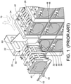
- FIG. 1 is a perspective view of a fan wall 20 that can be included as part of a computing device or system, such as a server.
- the components of the server are cooled by the fan wall 20 during server operation.
- the fan wall 20 in this example includes vertical walls 22, 24, and 26 that are formed from vertical sheets.
- the fan wall 20 also includes horizontal shelves 32, 34, and 36.
- a fan module such as fan module 40 may be removed from a respective socket 50.
- the socket 50 is defined by vertical walls 22 and 24, and shelf 32.
- the fan module 40 includes a rotatable bracket 52 that includes a knob 54.
- the bracket 52 rotates from an axis at the bottom edge of the fan module 40.
- the rotatable bracket 52 is moved to an upward position to lock the fan module 40 in place.
- a user can pull on the knob 54 and pull the bracket 52 down to release the fan module 40 from the socket 50.
- each of the sockets includes a fan flap in the respective sockets.
- An example fan flap is a fan flap 60 in the socket 50.
- the fan flap 60 is mounted on a hinge on the vertical wall 24. The fan flap 60 is normally forced by the insertion of the fan module 40 into the socket 50 to be rotated to a position flush against vertical wall 24.
- a removal of the fan module 40 from the socket 50 may occur if the example fan module 40 fails.
- the other fan modules 42, 44, 46, and 48 continue to operate to cool the server.
- the airflow from the other fans creates an air reflow, as shown by the arrows 70 creating a pressure drop.
- a spring mechanism causes the fan flap 60 to swing away from the vertical wall 24, as shown in FIG. 1 , to block the socket 50 formerly occupied by the fan module 40.
- the fan flap 60 therefore blocks air flow through the socket 50 that may impede the cooling generated by the air flow from the other fan modules.
- the fan flap 60 might move inwards toward the vertical wall 24 due to the pressure drop of the empty socket 50 overcoming the force of the spring mechanism.
- the fan flap 60 moves inward, it fails to block the socket 50, and air flow may occur through the socket 50, thereby impeding the cooling function of the fan wall 20.
- the fan flap fail rate increases as requirements for fan power grows dramatically in recent server systems. Thus, an effective anti-reflow mechanism to prevent fan flap failure is required.
- the US 2015/146381 A1 discloses an electronic device with a component detaching function including a casing, a cover and an electronic component.
- An opening is formed on the casing.
- the cover is adapted to shelter the opening.
- the cover is movably disposed on the casing close to the opening, and can move relative to the casing to be switched between a first position and a second portion.
- the cover includes a first connecting portion.
- the electronic component including a second connecting portion is detachably disposed on the opening.
- the second connecting portion is detachably assembled with the first connecting portion.
- the electronic component When the electronic component is separated from the casing, the electronic component utilizes an assembly of the first connecting portion and the second connecting portion to slide the cover relative to the casing, and the cover moves from the first position to the second portion.
- the US 2014/0313667 A1 discloses an electronic device includes a main body and a number of fan modules.
- the main body defines a number of vents in a top of the main body.
- the fan modules are mounted to the top of the main body.
- Each fan module includes a housing and a fan.
- the housing includes a side plate defining an opening aligned with the vents.
- a stop plate is pivotably connected to a first end of the opening, and is operable to cover the opening.
- the fan is mounted in the housing, and is near a second end of the opening opposite to the first end.
- the CN 106 714 529 A discloses a low-noise heat exchange equipment and a heat exchange system.
- the low-noise heat exchange equipment comprises a lower air passage, a base plate, a fan unit and an upper air passage, wherein the fan unit is detachably arranged in a space formed between the base plate and the upper air passage.
- the low-noise heat exchange equipment has the advantages that the noise influence to the external environment by the operation of the fan is effectively decreased; by adopting the detachable structure, the heat exchange equipment is easily replaced; especially when the fan fails, the quick replacement of the fan is guaranteed, and the influence to the normal running of a machine is avoided.
- an anti-reflow device for preventing failure of a swinging fan flap in a socket.
- the anti-reflow device comprises a plate, an attachment feature, an embossed feature, and a stopping feature.
- the plate has a proximal end and a distal end.
- the attachment feature is disposed at the proximal end of the plate, and is configured to attach the proximal end of the plate to a wall of the socket to allow the distal end of the plate to move relative to the wall.
- the embossed feature extends from the plate between the proximal end and the distal end.
- the embossed feature is configured to contact a fan module inserted into the socket.
- the stopping feature extends from the distal end of the plate and is configured to contact the swinging fan flap.
- the plate has a rectangular shape.
- the attachment feature includes one or more holes.
- Each of the one or more holes can be configured to receive at least one fastener to attach the plate to a wall of the socket.
- the plate is fabricated from metal, such as sheet metal or die cast metal, or from plastic.
- the stopping feature has a half-dome shape.
- the embossed feature has a rectangular shape.
- the anti-reflow device further comprises a relief cutout defined in the plate between the embossed feature and the stopping feature.
- the anti-reflow device is held by a fan module frame.
- the fan module frame comprises a side support, a bottom support, a top support, and a support tab.
- the side support has a top end and a bottom end.
- the top support has one end coupled to the top end of the side support.
- the bottom support has one end coupled to the bottom end of the side support.
- the support tab extends from the side support and is configured to hold the proximal end of the anti-reflow device.
- a modular fan assembly comprises a socket, a fan flap, and an anti-reflow device.
- the socket is configured to receive a fan module, and is defined by a first side wall, a second side wall, and a horizontal shelf.
- the fan flap is rotatably coupled to the first side wall and is configured to move in a curved path relative to the first side wall.
- the anti-reflow device is coupled to the second side wall and has a proximal end and a distal end.
- the anti-reflow device includes an attachment feature, an embossed feature, and a stopping feature.
- the attachment feature is disposed at the proximal end and is configured to attach the proximal end to the second side wall of the socket.
- the embossed feature is disposed between the proximal end and the distal end.
- the embossed feature is configured to contact a fan module responsive to the fan module being inserted into the socket.
- the stopping feature is disposed at the distal end and is configured to contact the swinging fan flap.
- the fan flap is configured to move in the curved path between a first position and a second position.
- a front edge of the fan flap is positioned between a front edge of the socket and the stopping feature.
- the front edge of the fan flap is positioned between the stopping feature and the first side wall.
- the stopping feature is configured to retain the fan flap in the first position when the fan module is removed from the socket.
- the socket is configured to receive the fan module between the first side wall and the second side wall.
- the anti-reflow device is coupled to a side of the second side wall opposite the fan module, such that the second side wall is positioned between the anti-reflow device and the fan module.
- a first aperture and a second aperture are defined in the second side wall.
- the embossed feature of the anti-reflow device extends through the first aperture defined in the second side wall.
- the stopping feature of the anti-reflow device extends through the second aperture defined in the second side wall, such that the stopping feature is positioned in the curved path of the fan flap.
- the fan module contacts the embossed feature responsive to the fan module being received in the socket.
- the contact between the fan module and the embossed feature causes the stopping feature to retract from the second aperture, such that the stopping feature is not positioned in the curved path of the fan flap.
- the fan flap rotates along the curved path to a first position responsive to the fan module being removed from the socket. In the first position, a front edge of the fan flap is disposed between the stopping feature and a front edge of the socket.
- the fan flap rotates along the curved path to a second position responsive to the fan module being fully inserted into the socket. In the second position, the front edge of the fan flap is disposed between the stopping feature and the second side wall.
- the stopping feature prevents the fan flap from rotating from the first position to the second position when the fan module is removed from the socket.
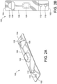
- FIG. 2A is a front perspective view of an example anti-reflow device 100 to prevent fan flaps from failing.
- FIG. 2B is a back view of the example anti-reflow device 100 shown in FIG. 2A .
- the anti-reflow device 100 is a roughly rectangular panel having a proximal end 102 and a distal end 104. Other shapes may also be used as long as the below described features are supported by the anti-reflow device.
- the anti-reflow device 100 is constructed of a flexible but strong material such as sheet metal, die cast metal, plastic, stainless steel (such as SUS304 stainless steel or SS304 stainless steel), copper alloys (such as beryllium copper) or any other suitable metal.
- the anti-reflow device could also be constructed of a flexible plastic.
- the anti-reflow device 100 has a front side 106 and an opposite back side 108.
- the anti-reflow device 100 includes one or more attachment features to mount the anti-reflow device to the socket wall.
- the one or more attachment features include two holes 110 and 112 defined near the proximal end 102 of the anti-reflow device.
- the holes 110 and 112 are configured to accommodate fasteners to attach to the socket wall.
- the fasteners can be, for example, rivets, pins, bolts, clamps, screws, nails, etc.
- An embossed feature 120 is formed near the center of the anti-reflow device 100 to extend from the front side 106.
- a relief cutout 130 can be formed near the distal end 104.
- the relief cutout 130 in this example is a semi-circular shape.
- a stopping feature 132 is formed to extend from the front side 106. In some implementations, the stopping feature 132 has a roughly half-dome shape, as shown in FIGs. 2A and 3B . However, the stopping feature 132 in other implementations may have different shapes.
- the anti-reflow device 100 does not include the relief cutout 130.
- FIG. 3A is a perspective view of a fan wall 200 and a corresponding socket 210 with the example anti-reflow device 100 of FIGs. 2A and 2B installed.
- FIG. 3B is a partially transparent perspective view of the socket 210 of FIG. 3A with the example anti-reflow device 100 of FIG. 2A installed.
- Air from the fan wall 200 cools the components of an electronic device such as a server.
- the fan wall 200 includes multiple fan modules-such as a fan module 212-that are inserted in sockets such as the socket 210.
- the fan wall 200 includes vertical walls 220 and 222.
- the vertical wall 220 is formed from two parallel side panels 224 and 226.
- the side panels 224 and 226 are joined at the top by a top panel 228.
- the opposite bottom of the side panels 224 and 226 are attached to a mounting bracket 230.
- a proximal panel 232 joins the front edges of the side panel 224 and 226.
- a distal panel 234 opposite the proximal panel 232 joins the back edges of the side panels 224 and 226.
- the side panel 226 includes an exterior surface 236 and an interior surface 238.
- the mounting bracket 230 is attached to a horizontal shelf 240.
- the vertical wall 222 also includes parallel side panels 250 and 252 that are attached to a proximal panel 254 and a top panel 256.
- the side panel 250 pivotably supports a fan flap 260.
- the vertical walls 220 and 222 and horizontal shelf 240 form the socket 210.
- a fan module may thus be inserted on the horizontal shelf 240 between the vertical walls 220 and 222.
- the fan module when inserted in the socket 210 pushes the fan flap 260 against the side panel 250.
- a spring mechanism forces the fan flap 260 to swing toward the exterior surface 236 of the side panel 224.
- the anti-reflow device 100 shown in FIGs. 2A-2B is mounted on the interior surface 238 of the side panel 226, as shown in detail in FIG. 3B .
- fasteners such as rivets (not shown) may be installed through holes 110 and 112 to attach the proximal end 102 of the anti-reflow device 100 to the proximal end of the side panel 226.
- the side panel 226 includes a forward aperture 270 and a rear aperture 272.
- the forward aperture 270 is shaped roughly the same as the embossed feature 120 of the anti-reflow device 100.
- the embossed feature 120 extends through the forward aperture 270, as shown in FIGs. 3A and 3B .
- the rear aperture 272 is shaped roughly the same as the stopping feature 132 of the anti-reflow device 100.
- the stopping feature 132 extends through the rear aperture 272, as shown in FIGs. 3A and 3B .
- the stopping feature 132 contacts the edge of the fan flap 260 and prevents the fan flap 260 from swinging inwardly (which would inadvertently stop the fan flap 260 from preventing reflow through the socket 210 when the fan module 212 is removed).
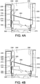
- FIG. 4A is a top view of a fan module 300 being initially inserted in the socket 210 in FIG. 3A with the anti-reflow device 100 in FIG. 2A installed.
- FIG. 4B is a top view of the fan module 300 continuing to be inserted into the socket 210 prior to the fan flap 260 swinging past the stopping feature 132 of the anti-reflow device 100.
- FIG. 4B thus shows the anti-reflow device 100 being forced away from the interior surface 238 of the side panel 226 towards the side panel 224 by the fan module 300.
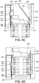
- FIG. 4C is a top view of the fan module 300 being still continuing to be inserted into the socket 210 after the fan flap 260 swings past the stopping feature 132 of the anti-reflow device 100.
- FIG. 4D is a top view of the fan module 300 being fully inserted into the socket 210 such that the fan flap 260 is flush against the exterior surface 258 of the side panel 250.
- a back edge of the fan flap 260 is attached to an exterior surface 258 of the side panel 250 via a hinge 310.
- a spring 312 is attached between the fan flap 260 and the exterior surface 258 of the side panel 250. The spring 312 forces the fan flap 260 to be rotated about the hinge 310 into a position blocking the socket 210.
- a front edge of the fan flap 260 includes a tab 320 that is positioned distally from the stopping feature 132 of the anti-reflow device 100 when the fan flap 260 blocks the socket 210, e.g., between a front edge of the socket 210 and the stopping feature 132.
- the stopping feature 132 extends outward from the exterior surface 236 of the side panel 226, through the rear aperture 272 and contacts the tab 320.
- the embossed feature 120 extends outward from the exterior surface 236 of the side panel 226 through the forward aperture 270.
- the stopping feature 132 prevents the fan flap 260 from rotating inward toward the exterior surface 258 of the side panel 250.
- the fan flap 260 blocks any airflow through the socket 210.
- the fan module 300 may be inserted into the socket 210 and onto the horizontal shelf 240 by pushing the fan module 300 into the socket 210. As the fan module 300 is inserted further in the socket 210 and onto the horizontal shelf 240 as shown in FIG. 4B , the side of the fan module 300 near the exterior surface 236 of the side panel 226 contacts the embossed feature 120 of the anti-reflow device 100, which extends out from the forward aperture 270. Since only the proximal end 102 of the anti-reflow device 100 is attached to the interior surface 238 of the side panel 226, the distal end 104 of the anti-reflow device 100 is pushed away from the interior surface 238 of the side panel 226.
- This curved path can be circular, or can generally have any suitable amount of curvature, e.g., can have any suitable radius of curvature. In some implementations, this path is straight, or comprises a series of straight paths.
- the position of the fan flap 260 and the tab 320 is also considered to be the first position, which is generally any position of the tab 320 and the fan flap 260 prior to swinging past the rear aperture 272.
- the fan module 300 As shown in FIG. 4C , as the fan module 300 continues to be inserted into the socket 210, the fan module 300 travels past the forward and rear apertures 270, 272 in the side panel 226 and the fan flap 260 continues to rotate towards the side panel 250. Because the stopping feature 132 has been forced away from the exterior surface 236 of the side panel 226, the stopping feature 132 no longer contacts the tab 320. This allows the fan flap 260 to be pushed past the rear aperture 272 to a second position. In this second position, the tab 320 of the fan flap 260 is positioned between (i) the stopping feature 132 and the rear aperture 272 from which the stopping feature 132 extends out of, and (ii) the exterior surface 258 of the side panel 250.
- the fan flap 260 can be rotated all the way towards the side panel 250 such that the fan flap 260 is flush against the exterior surface 258 of the side panel 250.
- This position as shown in FIG. 4D is also considered to be the second position, which is generally any position of the tab 320 and the fan flap 260 after the tab 320 swings past the rear aperture 272.
- the fan flap 260 no longer blocks the socket 210, allowing the fan module 300 to circulate air.
- FIG. 5A shows the socket 210 once the fan module has been completely removed from the socket 210.
- FIG. 5B shows a zoomed-in view of the circular dashed area of FIG. 5A , showing the stopping feature 132 and the tab 320 of the fan flap 260 when the fan module has been completely removed from the socket.
- the spring 312 forces the fan flap 260 to be rotated away from the exterior surface 258 of the side panel 250 via the hinge 310.
- the fan module 300 remains in contact with the embossed feature 120 of the anti-reflow device 100.
- the distal end 104 of the anti-reflow device 100 is still forced away from the interior surface 238 of the side panel 226, and the stopping feature 132 is still retracted from the rear aperture 272.
- the front edge of the fan flap 260 passes from the distal side of the rear aperture 272 (e.g., between the stopping feature 132 and the exterior surface 258 of the side panel 250) to the proximal side of the rear aperture 272 (e.g., between the stopping feature 132 and the front edge of the socket 210).
- the fan module 300 can be completely removed from the socket 210. Due to the force of the spring 312, the fan flap 260 will have swung to the first position between the stopping feature 132 and the front edge of the socket 210, thus covering the socket 210. However, because the fan module 300 no longer contacts the embossed feature 120 of the anti-reflow device, the distal end 104 of the anti-reflow device 100 is not forced away from the interior surface 238 of the side panel 226. The stopping feature 132 of the anti-reflow device 100 will thus again extend through the rear aperture 272 of the side panel 226.
- the tab 320 of the fan flap 260 will contact the stopping feature 132, which prevents the fan flap 260 from swinging back to the second position between the stopping feature 132 and the exterior surface 258 of the side panel 250. This in turn prevents air from reflowing back the socket 210.
- the stopping feature 132 thus retains the tab 320 of the fan flap 260 on the proximal side of the rear aperture 272, which prevents any air from flowing back through the socket 210.
- FIG. 6 is a back perspective view of the fan flap 260 being prevented from failure by the anti-reflow device 100 shown in the figures above.
- the fan flap 260 is supported by the hinge 310 that is attached to the side panel 250.
- the fan flap 260 swings to a position between the exterior surface of the side panel 250 and the exterior surface 236 of the side panel 226 to block the socket 210.
- the stopping feature 132 extends out of the rear aperture 272 from the exterior surface 236 of the side panel 226.
- the stopping feature 132 then contacts the tab 320 and prevents the fan flap 260 from rotating inwardly by air pressure (shown by arrow 500).
- the fan flap 260 prevents air flow through the vacant socket 210.
- FIG. 7 is a perspective view of an example support frame 600 that may be used to install the anti-reflow device in FIG. 2A into a socket, when the anti-reflow device 100 cannot be directly installed on one of the side panels of the socket.
- the support frame 600 includes a pair of side supports 612 and 614. The top ends of the side support 612 and the side support 614 are joined by a top support 616. A bottom support 618 is joined to the bottom end of the side support 612.
- the side support 612 has a relatively wider top edge that is attached to a wider end of the top support 616.
- the top support 616 tapers to a narrower edge that is attached to the other side support 614.
- the support frame 600 is made of a polymer, such as plastic, acrylonitrile butadiene styrene (ABS), high-density polyethylene (HDPE), low-density polyethylene (LDPE), or any other suitable polymer.
- ABS acrylonitrile butadiene styrene
- HDPE high-density polyethylene
- LDPE low-density polyethylene
- the support frame 600 can also be made of any suitable type of metal, rubber, silicon-like materials, or any other material that is flexible and can deform.
- the side support 612 includes a proximal mounting tab 620.
- the proximal end 102 of the anti-reflow device 100 can be attached to the proximal mounting tab 620.
- the proximal mounting tab 620 includes holes that align with the holes 110 and 112 of the anti-reflow device 100 (in FIGs. 2A and 2B ). Fasteners such as rivets or other mechanisms may be inserted through the holes 110 and 112 of the anti-reflow device 100 and the proximal mounting tab 620 to attach the anti-reflow device 100 to the proximal mounting tab 620.
- the anti-reflow device 100 extends from the proximal mounting tab 620 to allow the distal end 104 to be flexed away from the side support 612.
- the embossed feature 120 and the stopping feature 132 may be moved between a position that extends from the plane of the side support 612 to a position behind the plane of the side support 612.
- a distally extending tab 630 allows additional stability against the walls of a socket.
- the distally extending tab 630 includes a mounting hole 632.
- the top end of the side support 612 includes a mounting tab 640 with a mounting hole 642.
- the end of the bottom support 618 opposite from the end attached to the side support 612 includes a mounting tab 650 that can have a mounting hole 652.
- FIG. 8 is a perspective view of fan wall 700 that includes a socket 710 with the support frame 600 in FIG. 7 to allow the anti-reflow device 100 in FIG. 2A to be installed.
- the socket 710 is defined by two side walls 712 and 714, a top shelf 716, and a bottom shelf 718.
- the side walls 712 and 714 are mounted on the bottom shelf 718.
- the side walls 712 and 714 include corresponding exterior surfaces 722 and 724.
- a fan flap 730 is attached via a hinge to the exterior surface 724. The fan flap 730 swings between a position flush against the exterior surface 724 and a position between the exterior surfaces 722 and 724 to block the socket 710.
- the anti-reflow device 100 is attached to the support frame 600.
- the support frame 600 with the attached anti-reflow device 100 is then inserted in the socket 710.
- the side supports 612 and 614 are in contact with the side walls 712 and 714, respectively, while the top support 616 and the bottom support 618 are in contact with the shelves 716 and 718, respectively, to provide support for an inserted fan module.
- the support frame 600 deforms slightly when being inserted into the socket, and thus can snap into the socket 710 and be maintained in the socket 710 via a friction fit.
- clips, latches, rods, pins, barbed features, or other fasteners may be used to secure the support frame 600 in the socket 710.
- the anti-reflow device 100 When the support frame 600 is inserted in the socket 710, the anti-reflow device 100 is held between the exterior surface 722 of the side wall 712 and the proximal mounting tab 620 of the support frame 600.
- the distally extending tab 630 provides additional stability for the support of the anti-reflow device 100 when the support frame 600 is installed in the socket.
- the distal end 104 of the anti-reflow device 100 extends into the socket 710 and may be pushed back by the insertion of the fan module.
- the fan flap 730 rotates to block the socket 710.
- the stopping feature 132 of the anti-reflow device 100 prevents the fan flap 730 from failing by stopping any inward rotation of the fan flap 730.
- the fan flap 730 thus continues to block air flow through the socket 710 when the fan module is removed.
Landscapes
- Engineering & Computer Science (AREA)
- Microelectronics & Electronic Packaging (AREA)
- Physics & Mathematics (AREA)
- Thermal Sciences (AREA)
- General Engineering & Computer Science (AREA)
- Mechanical Engineering (AREA)
- Theoretical Computer Science (AREA)
- Aviation & Aerospace Engineering (AREA)
- Human Computer Interaction (AREA)
- General Physics & Mathematics (AREA)
- Cooling Or The Like Of Electrical Apparatus (AREA)
- Structures Of Non-Positive Displacement Pumps (AREA)
Claims (14)
- Rückflussverhinderungsvorrichtung (100), um ein Versagen einer schwingenden Lüfterklappe (260, 730) in einem Sockel (210, 710) zu verhindern, wobei die Rückflussverhinderungsvorrichtung (100) aufweist:eine Platte, die ein proximales Ende (102) und ein distales Ende (104) aufweist; undein Befestigungsmerkmal (110, 112), das an dem proximalen Ende (102) der Platte angeordnet ist, wobei das Befestigungsmerkmal (110, 112) so ausgestaltet ist, dass es das proximale Ende (102) der Platte an einer Wand (220, 712) des Sockels (210, 710) befestigt, damit sich das distale Ende (104) der Platte relativ zu der Wand (220, 712) bewegen kann; gekennzeichnet durchein geprägtes Merkmal (120), das sich von der Platte zwischen dem proximalen Ende (102) und dem distalen Ende (104) erstreckt, wobei das geprägte Merkmal (120) so ausgestaltet ist, dass es sich durch eine vordere Öffnung (270) an der Wand (220, 712) des Sockels (210, 710) erstreckt, um ein in den Sockel (210, 710) eingesetztes Lüftermodul (300) zu berühren; undein Anhalteelement (132), das sich von dem distalen Ende (104) der Platte erstreckt, wobei das Anhalteelement (132) so ausgestaltet ist, dass es sich durch eine hintere Öffnung (272) an der Wand (220, 712) des Sockels (210, 710) erstreckt, um die schwingende Lüfterklappe (260) zu berühren.
- Rückflussverhinderungsvorrichtung (100) nach Anspruch 1, wobei die Platte eine rechteckige Form aufweist und die Platte aus einem Metall oder einem Kunststoff hergestellt worden ist, wobei das Anhalteelement (132) eine Halbkuppelform aufweist und wobei das geprägte Merkmal (120) eine rechteckige Form aufweist.
- Rückflussverhinderungsvorrichtung (100) nach Anspruch 1 oder 2, wobei das Befestigungsmerkmal ein oder mehrere Löcher (110, 112) aufweist und wobei jedes des einen oder der mehreren Löcher (110, 112) so ausgestaltet ist, dass es mindestens ein Befestigungselement aufnehmen kann.
- Rückflussverhinderungsvorrichtung (100) nach einem der Ansprüche 1 bis 3, die ferner einen Reliefausschnitt (130) aufweist, der in der Platte zwischen dem geprägten Merkmal (120) und dem Anhalteelement (132) bestimmt ist.
- Modulare Lüfterbaugruppe mit der Rückflussverhinderungsvorrichtung (100) nach einem der Ansprüche 1 bis 4, wobei die modulare Lüfterbaugruppe aufweist:den Sockel (210), der durch eine erste Seitenwand (222), eine zweite Seitenwand (220) und einen horizontalen Boden (240) bestimmt ist, wobei der Sockel (210) so ausgestaltet ist, dass er das Lüftermodul zwischen der ersten Seitenwand (222) und der zweiten Seitenwand (220) aufnimmt;die Lüfterklappe (260), die drehbar mit der ersten Seitenwand (222) verbunden ist, wobei die Lüfterklappe (260) so ausgestaltet ist, dass sie sich zwischen einer ersten Position und einer zweiten Position bewegt; unddie Rückflussverhinderungsvorrichtung (100), die mit der zweiten Seitenwand (220) des Sockels (210) verbunden ist.
- Modulare Lüfterbaugruppe nach Anspruch 5, wobei, wenn sich die Lüfterklappe (260) in der ersten Position befindet, eine vordere Kante der Lüfterklappe (260) zwischen einer vorderen Kante des Sockels (210) und dem Anhalteelement (132) angeordnet ist.
- Modulare Lüfterbaugruppe nach Anspruch 5 oder 6, wobei, wenn sich die Lüfterklappe (260) in der zweiten Position befindet, die vordere Kante der Lüfterklappe (260) zwischen dem Anschlagelement (132) und der ersten Seitenwand (222) angeordnet ist.
- Modulare Lüfterbaugruppe nach einem der Ansprüche 5 bis 7, wobei das Anschlagelement (132) so ausgestaltet ist, dass es die Lüfterklappe (260) in der ersten Position hält, wenn das Lüftermodul (300) aus dem Sockel (210) entfernt wird.
- Modulare Lüfterbaugruppe nach einem der Ansprüche 5 bis 8, wobei die Rückflussverhinderungsvorrichtung (100) mit einer Seite der zweiten Seitenwand (220) gegenüber dem Lüftermodul (300) auf eine solche Weise verbunden ist, dass die zweite Seitenwand (220) zwischen der Rückflussverhinderungsvorrichtung (100) und dem Lüftermodul (300) angeordnet ist.
- Modulare Lüfterbaugruppe nach einem der Ansprüche 5 bis 9, wobei eine erste Öffnung und eine zweite Öffnung in der zweiten Seitenwand (220) bestimmt sind.
- Modulare Lüfterbaugruppe nach Anspruch 10, wobei das geprägte Merkmal der Rückflussverhinderungsvorrichtung (100) so ausgestaltet ist, dass es sich durch die erste Öffnung (270) in der zweiten Seitenwand (220) erstreckt, und wobei das Anhalteelement (132) der Rückflussverhinderungsvorrichtung (100) so ausgestaltet ist, dass es sich durch die zweite Öffnung (272) in der zweiten Seitenwand (220) auf eine solche Weise erstreckt, dass das Anhalteelement (132) in der gekrümmten Bahn der Lüfterklappe (260) angeordnet ist.
- Modulare Lüfterbaugruppe nach einem der Ansprüche 5 bis 11, wobei das Lüftermodul (300) das geprägte Merkmal (120) berührt, wenn das Lüftermodul (300) in den Sockel (210) aufgenommen ist.
- Modulare Lüfterbaugruppe nach einem der Ansprüche 12, wobei der Kontakt zwischen dem Lüftermodul (300) und dem geprägten Merkmal (120) bewirkt, dass sich das Anhalteelement (132) aus der zweiten Öffnung (272) auf eine solche Weise zurückzieht, dass das Anhalteelement (132) nicht in der gekrümmten Bahn der Lüfterklappe (260) angeordnet ist.
- Modulare Lüfterbaugruppe nach Anspruch 13, wobei sich die Lüfterklappe (260) entlang des gekrümmten Weges in eine erste Position auf eine solche Weise dreht, dass eine vordere Kante der Lüfterklappe (260) zwischen dem Anhalteelement (132) und einer vorderen Kante des Sockels (210) angeordnet ist, wenn das Lüftermodul (300) aus dem Sockel (210) entfernt wird, und wobei sich die Lüfterklappe (260) entlang des gekrümmten Weges in eine zweite Position auf eine solche Weise dreht, dass die vordere Kante der Lüfterklappe (260) zwischen dem Anhalteelement (132) und der zweiten Seitenwand (220) angeordnet ist, wenn das Lüftermodul (300) vollständig in den Sockel (210) eingesetzt ist, wobei das Anhalteelement (132) verhindert, dass sich die Lüfterklappe (260) von der ersten Position in die zweite Position dreht, wenn das Lüftermodul (300) aus dem Sockel (210) entfernt wird.
Applications Claiming Priority (1)
| Application Number | Priority Date | Filing Date | Title |
|---|---|---|---|
| US16/354,785 US11536292B2 (en) | 2019-03-15 | 2019-03-15 | Mechanism for preventing reflow for fan flap failure |
Publications (2)
| Publication Number | Publication Date |
|---|---|
| EP3709782A1 EP3709782A1 (de) | 2020-09-16 |
| EP3709782B1 true EP3709782B1 (de) | 2022-03-02 |
Family
ID=67659075
Family Applications (1)
| Application Number | Title | Priority Date | Filing Date |
|---|---|---|---|
| EP19192069.3A Active EP3709782B1 (de) | 2019-03-15 | 2019-08-16 | Mechanismus zum verhindern des rückflusses bei ausfall einer lüfterklappe |
Country Status (5)
| Country | Link |
|---|---|
| US (1) | US11536292B2 (de) |
| EP (1) | EP3709782B1 (de) |
| JP (1) | JP6829748B2 (de) |
| CN (1) | CN111692129B (de) |
| TW (1) | TWI699158B (de) |
Families Citing this family (4)
| Publication number | Priority date | Publication date | Assignee | Title |
|---|---|---|---|---|
| US12168249B1 (en) * | 2016-05-02 | 2024-12-17 | Jackie Robinson | Plumbing supply transport case and method of sanitizing and transporting plumbing supplies |
| CN115344098A (zh) | 2021-05-12 | 2022-11-15 | 富联精密电子(天津)有限公司 | 防风回流装置和服务器 |
| TWI771000B (zh) * | 2021-05-12 | 2022-07-11 | 新加坡商鴻運科股份有限公司 | 防風回流裝置與伺服器 |
| CN113391680A (zh) * | 2021-06-11 | 2021-09-14 | 上海顺诠科技有限公司 | 防回流机箱 |
Family Cites Families (18)
| Publication number | Priority date | Publication date | Assignee | Title |
|---|---|---|---|---|
| TWM246696U (en) * | 2003-11-18 | 2004-10-11 | Quanta Comp Inc | Removable fan module |
| US7530890B2 (en) * | 2004-06-30 | 2009-05-12 | Shuttle Inc. | Quickly detached cooling fan mounting bracket for computer |
| US8672734B2 (en) * | 2010-12-13 | 2014-03-18 | Robert Labrecque | Extraction fan assembly including a damper that closes firmly when the fan is not running and reduces the pressure drop when the fan is running at full speed |
| US8740560B2 (en) * | 2010-12-17 | 2014-06-03 | Hong Fu Jin Precision Industry (Shenzhen) Co., Ltd. | Fan module |
| CN102548344A (zh) * | 2010-12-24 | 2012-07-04 | 鸿富锦精密工业(深圳)有限公司 | 风扇组合 |
| TW201441488A (zh) * | 2013-04-22 | 2014-11-01 | Hon Hai Prec Ind Co Ltd | 電子裝置及其風扇模組 |
| JP2014232749A (ja) * | 2013-05-28 | 2014-12-11 | 富士通テレコムネットワークス株式会社 | 冷却装置 |
| TWI590032B (zh) * | 2013-09-09 | 2017-07-01 | 緯創資通股份有限公司 | 具有閉合功能之阻風門機構及其電子裝置 |
| TWI528884B (zh) * | 2013-11-26 | 2016-04-01 | 緯創資通股份有限公司 | 具有抽換元件功能的電子裝置 |
| US9913401B2 (en) * | 2014-05-29 | 2018-03-06 | Arris Enterprises Llc | Pivotable fan assembly and associated systems |
| CN104284536B (zh) * | 2014-10-28 | 2017-06-06 | 深圳绿色云图科技有限公司 | 服务器机柜及具有其的机柜组和液体浸没冷却服务器系统 |
| US9850908B2 (en) * | 2015-01-27 | 2017-12-26 | International Business Machines Corporation | Variable inlet vanes |
| US10470336B2 (en) * | 2015-08-07 | 2019-11-05 | Quanta Computer Inc. | Quick release fan module |
| TWM532715U (zh) * | 2016-07-15 | 2016-11-21 | Chenbro Micom Co Ltd | 機箱內之防回流擋板結構 |
| US10264711B2 (en) * | 2016-11-30 | 2019-04-16 | Data Marine, LLC | Data vessel integrated with cooling and docking station with ancillary service |
| CN106714529A (zh) * | 2017-03-10 | 2017-05-24 | 成都成广电视设备有限公司 | 一种低噪音热交换设备及热交换系统 |
| TWI658769B (zh) * | 2018-08-16 | 2019-05-01 | 緯創資通股份有限公司 | 具有可旋轉的氣流遮擋件的機箱及伺服器 |
| CN111142625B (zh) * | 2018-11-05 | 2021-08-24 | 纬联电子科技(中山)有限公司 | 固定架组与服务器 |
-
2019
- 2019-03-15 US US16/354,785 patent/US11536292B2/en active Active
- 2019-05-24 TW TW108118152A patent/TWI699158B/zh active
- 2019-06-06 CN CN201910489933.4A patent/CN111692129B/zh active Active
- 2019-07-16 JP JP2019131276A patent/JP6829748B2/ja active Active
- 2019-08-16 EP EP19192069.3A patent/EP3709782B1/de active Active
Also Published As
| Publication number | Publication date |
|---|---|
| CN111692129B (zh) | 2021-08-20 |
| EP3709782A1 (de) | 2020-09-16 |
| US11536292B2 (en) | 2022-12-27 |
| TW202037256A (zh) | 2020-10-01 |
| JP2020149659A (ja) | 2020-09-17 |
| CN111692129A (zh) | 2020-09-22 |
| JP6829748B2 (ja) | 2021-02-10 |
| US20200291962A1 (en) | 2020-09-17 |
| TWI699158B (zh) | 2020-07-11 |
Similar Documents
| Publication | Publication Date | Title |
|---|---|---|
| EP3709782B1 (de) | Mechanismus zum verhindern des rückflusses bei ausfall einer lüfterklappe | |
| US7800902B2 (en) | Air backflow prevention in an enclosure | |
| US6115250A (en) | Computer and an assembly and method for cooling a computer | |
| US6031717A (en) | Back flow limiting device for failed redundant parallel fan | |
| TWI741301B (zh) | 用於不同形式之卡的通用載體 | |
| US7416481B2 (en) | Blower exhaust backflow damper | |
| TWI505767B (zh) | 散熱裝置 | |
| EP1517221B1 (de) | Elektronische Baugruppe einschliesslich eines Gehäuses mit einem drehbaren Teil | |
| US9968006B2 (en) | Locking louver assembly for air-moving assembly | |
| US7755889B2 (en) | Air Manifold for electronic module enclosure | |
| CN102541222A (zh) | 机架式服务器系统 | |
| WO2002089549A1 (en) | Valve | |
| CN102300421A (zh) | 电子装置壳体 | |
| HK1220265A1 (zh) | 風扇板 | |
| US11425844B2 (en) | Riser module with an integrated cooling duct | |
| US10542634B2 (en) | Fan reconfiguration and displacement due to a failed or failing fan | |
| US7046517B2 (en) | Electrically isolated semi-locking hinge for cooling system | |
| EP2254019B1 (de) | Lüftereinheit | |
| US10660235B2 (en) | Fan with pivotable blades, and corresponding electronics cooling system and methods | |
| EP3505771B1 (de) | Kühlgebläseanordnung mit rückflussschutzvorrichtung | |
| US20070019382A1 (en) | Hot swappable cooling fan system | |
| CN215769638U (zh) | 导风罩及服务器 | |
| WO2000052695A1 (en) | Computer system with dummy drive for optimal cooling efficiency | |
| US11737245B2 (en) | Air flow control in data storage systems | |
| CN218273310U (zh) | 防回风装置及散热系统 |
Legal Events
| Date | Code | Title | Description |
|---|---|---|---|
| PUAI | Public reference made under article 153(3) epc to a published international application that has entered the european phase |
Free format text: ORIGINAL CODE: 0009012 |
|
| STAA | Information on the status of an ep patent application or granted ep patent |
Free format text: STATUS: REQUEST FOR EXAMINATION WAS MADE |
|
| 17P | Request for examination filed |
Effective date: 20200602 |
|
| AK | Designated contracting states |
Kind code of ref document: A1 Designated state(s): AL AT BE BG CH CY CZ DE DK EE ES FI FR GB GR HR HU IE IS IT LI LT LU LV MC MK MT NL NO PL PT RO RS SE SI SK SM TR |
|
| AX | Request for extension of the european patent |
Extension state: BA ME |
|
| GRAP | Despatch of communication of intention to grant a patent |
Free format text: ORIGINAL CODE: EPIDOSNIGR1 |
|
| STAA | Information on the status of an ep patent application or granted ep patent |
Free format text: STATUS: GRANT OF PATENT IS INTENDED |
|
| INTG | Intention to grant announced |
Effective date: 20211125 |
|
| GRAS | Grant fee paid |
Free format text: ORIGINAL CODE: EPIDOSNIGR3 |
|
| GRAA | (expected) grant |
Free format text: ORIGINAL CODE: 0009210 |
|
| STAA | Information on the status of an ep patent application or granted ep patent |
Free format text: STATUS: THE PATENT HAS BEEN GRANTED |
|
| AK | Designated contracting states |
Kind code of ref document: B1 Designated state(s): AL AT BE BG CH CY CZ DE DK EE ES FI FR GB GR HR HU IE IS IT LI LT LU LV MC MK MT NL NO PL PT RO RS SE SI SK SM TR |
|
| REG | Reference to a national code |
Ref country code: GB Ref legal event code: FG4D |
|
| REG | Reference to a national code |
Ref country code: CH Ref legal event code: EP Ref country code: AT Ref legal event code: REF Ref document number: 1473360 Country of ref document: AT Kind code of ref document: T Effective date: 20220315 |
|
| REG | Reference to a national code |
Ref country code: DE Ref legal event code: R096 Ref document number: 602019012042 Country of ref document: DE |
|
| REG | Reference to a national code |
Ref country code: IE Ref legal event code: FG4D |
|
| REG | Reference to a national code |
Ref country code: LT Ref legal event code: MG9D |
|
| REG | Reference to a national code |
Ref country code: NL Ref legal event code: MP Effective date: 20220302 |
|
| PG25 | Lapsed in a contracting state [announced via postgrant information from national office to epo] |
Ref country code: SE Free format text: LAPSE BECAUSE OF FAILURE TO SUBMIT A TRANSLATION OF THE DESCRIPTION OR TO PAY THE FEE WITHIN THE PRESCRIBED TIME-LIMIT Effective date: 20220302 Ref country code: RS Free format text: LAPSE BECAUSE OF FAILURE TO SUBMIT A TRANSLATION OF THE DESCRIPTION OR TO PAY THE FEE WITHIN THE PRESCRIBED TIME-LIMIT Effective date: 20220302 Ref country code: NO Free format text: LAPSE BECAUSE OF FAILURE TO SUBMIT A TRANSLATION OF THE DESCRIPTION OR TO PAY THE FEE WITHIN THE PRESCRIBED TIME-LIMIT Effective date: 20220602 Ref country code: LT Free format text: LAPSE BECAUSE OF FAILURE TO SUBMIT A TRANSLATION OF THE DESCRIPTION OR TO PAY THE FEE WITHIN THE PRESCRIBED TIME-LIMIT Effective date: 20220302 Ref country code: HR Free format text: LAPSE BECAUSE OF FAILURE TO SUBMIT A TRANSLATION OF THE DESCRIPTION OR TO PAY THE FEE WITHIN THE PRESCRIBED TIME-LIMIT Effective date: 20220302 Ref country code: ES Free format text: LAPSE BECAUSE OF FAILURE TO SUBMIT A TRANSLATION OF THE DESCRIPTION OR TO PAY THE FEE WITHIN THE PRESCRIBED TIME-LIMIT Effective date: 20220302 Ref country code: BG Free format text: LAPSE BECAUSE OF FAILURE TO SUBMIT A TRANSLATION OF THE DESCRIPTION OR TO PAY THE FEE WITHIN THE PRESCRIBED TIME-LIMIT Effective date: 20220602 |
|
| REG | Reference to a national code |
Ref country code: AT Ref legal event code: MK05 Ref document number: 1473360 Country of ref document: AT Kind code of ref document: T Effective date: 20220302 |
|
| PG25 | Lapsed in a contracting state [announced via postgrant information from national office to epo] |
Ref country code: PL Free format text: LAPSE BECAUSE OF FAILURE TO SUBMIT A TRANSLATION OF THE DESCRIPTION OR TO PAY THE FEE WITHIN THE PRESCRIBED TIME-LIMIT Effective date: 20220302 Ref country code: LV Free format text: LAPSE BECAUSE OF FAILURE TO SUBMIT A TRANSLATION OF THE DESCRIPTION OR TO PAY THE FEE WITHIN THE PRESCRIBED TIME-LIMIT Effective date: 20220302 Ref country code: GR Free format text: LAPSE BECAUSE OF FAILURE TO SUBMIT A TRANSLATION OF THE DESCRIPTION OR TO PAY THE FEE WITHIN THE PRESCRIBED TIME-LIMIT Effective date: 20220603 Ref country code: FI Free format text: LAPSE BECAUSE OF FAILURE TO SUBMIT A TRANSLATION OF THE DESCRIPTION OR TO PAY THE FEE WITHIN THE PRESCRIBED TIME-LIMIT Effective date: 20220302 |
|
| PG25 | Lapsed in a contracting state [announced via postgrant information from national office to epo] |
Ref country code: NL Free format text: LAPSE BECAUSE OF FAILURE TO SUBMIT A TRANSLATION OF THE DESCRIPTION OR TO PAY THE FEE WITHIN THE PRESCRIBED TIME-LIMIT Effective date: 20220302 |
|
| PG25 | Lapsed in a contracting state [announced via postgrant information from national office to epo] |
Ref country code: SM Free format text: LAPSE BECAUSE OF FAILURE TO SUBMIT A TRANSLATION OF THE DESCRIPTION OR TO PAY THE FEE WITHIN THE PRESCRIBED TIME-LIMIT Effective date: 20220302 Ref country code: SK Free format text: LAPSE BECAUSE OF FAILURE TO SUBMIT A TRANSLATION OF THE DESCRIPTION OR TO PAY THE FEE WITHIN THE PRESCRIBED TIME-LIMIT Effective date: 20220302 Ref country code: RO Free format text: LAPSE BECAUSE OF FAILURE TO SUBMIT A TRANSLATION OF THE DESCRIPTION OR TO PAY THE FEE WITHIN THE PRESCRIBED TIME-LIMIT Effective date: 20220302 Ref country code: PT Free format text: LAPSE BECAUSE OF FAILURE TO SUBMIT A TRANSLATION OF THE DESCRIPTION OR TO PAY THE FEE WITHIN THE PRESCRIBED TIME-LIMIT Effective date: 20220704 Ref country code: EE Free format text: LAPSE BECAUSE OF FAILURE TO SUBMIT A TRANSLATION OF THE DESCRIPTION OR TO PAY THE FEE WITHIN THE PRESCRIBED TIME-LIMIT Effective date: 20220302 Ref country code: CZ Free format text: LAPSE BECAUSE OF FAILURE TO SUBMIT A TRANSLATION OF THE DESCRIPTION OR TO PAY THE FEE WITHIN THE PRESCRIBED TIME-LIMIT Effective date: 20220302 Ref country code: AT Free format text: LAPSE BECAUSE OF FAILURE TO SUBMIT A TRANSLATION OF THE DESCRIPTION OR TO PAY THE FEE WITHIN THE PRESCRIBED TIME-LIMIT Effective date: 20220302 |
|
| PG25 | Lapsed in a contracting state [announced via postgrant information from national office to epo] |
Ref country code: IS Free format text: LAPSE BECAUSE OF FAILURE TO SUBMIT A TRANSLATION OF THE DESCRIPTION OR TO PAY THE FEE WITHIN THE PRESCRIBED TIME-LIMIT Effective date: 20220702 Ref country code: AL Free format text: LAPSE BECAUSE OF FAILURE TO SUBMIT A TRANSLATION OF THE DESCRIPTION OR TO PAY THE FEE WITHIN THE PRESCRIBED TIME-LIMIT Effective date: 20220302 |
|
| REG | Reference to a national code |
Ref country code: DE Ref legal event code: R097 Ref document number: 602019012042 Country of ref document: DE |
|
| PLBE | No opposition filed within time limit |
Free format text: ORIGINAL CODE: 0009261 |
|
| STAA | Information on the status of an ep patent application or granted ep patent |
Free format text: STATUS: NO OPPOSITION FILED WITHIN TIME LIMIT |
|
| PG25 | Lapsed in a contracting state [announced via postgrant information from national office to epo] |
Ref country code: DK Free format text: LAPSE BECAUSE OF FAILURE TO SUBMIT A TRANSLATION OF THE DESCRIPTION OR TO PAY THE FEE WITHIN THE PRESCRIBED TIME-LIMIT Effective date: 20220302 |
|
| 26N | No opposition filed |
Effective date: 20221205 |
|
| PG25 | Lapsed in a contracting state [announced via postgrant information from national office to epo] |
Ref country code: SI Free format text: LAPSE BECAUSE OF FAILURE TO SUBMIT A TRANSLATION OF THE DESCRIPTION OR TO PAY THE FEE WITHIN THE PRESCRIBED TIME-LIMIT Effective date: 20220302 |
|
| PG25 | Lapsed in a contracting state [announced via postgrant information from national office to epo] |
Ref country code: MC Free format text: LAPSE BECAUSE OF FAILURE TO SUBMIT A TRANSLATION OF THE DESCRIPTION OR TO PAY THE FEE WITHIN THE PRESCRIBED TIME-LIMIT Effective date: 20220302 |
|
| REG | Reference to a national code |
Ref country code: CH Ref legal event code: PL |
|
| PG25 | Lapsed in a contracting state [announced via postgrant information from national office to epo] |
Ref country code: LU Free format text: LAPSE BECAUSE OF NON-PAYMENT OF DUE FEES Effective date: 20220816 Ref country code: LI Free format text: LAPSE BECAUSE OF NON-PAYMENT OF DUE FEES Effective date: 20220831 Ref country code: CH Free format text: LAPSE BECAUSE OF NON-PAYMENT OF DUE FEES Effective date: 20220831 |
|
| REG | Reference to a national code |
Ref country code: BE Ref legal event code: MM Effective date: 20220831 |
|
| P01 | Opt-out of the competence of the unified patent court (upc) registered |
Effective date: 20230505 |
|
| PG25 | Lapsed in a contracting state [announced via postgrant information from national office to epo] |
Ref country code: IT Free format text: LAPSE BECAUSE OF FAILURE TO SUBMIT A TRANSLATION OF THE DESCRIPTION OR TO PAY THE FEE WITHIN THE PRESCRIBED TIME-LIMIT Effective date: 20220302 Ref country code: IE Free format text: LAPSE BECAUSE OF NON-PAYMENT OF DUE FEES Effective date: 20220816 |
|
| PG25 | Lapsed in a contracting state [announced via postgrant information from national office to epo] |
Ref country code: BE Free format text: LAPSE BECAUSE OF NON-PAYMENT OF DUE FEES Effective date: 20220831 |
|
| PG25 | Lapsed in a contracting state [announced via postgrant information from national office to epo] |
Ref country code: CY Free format text: LAPSE BECAUSE OF FAILURE TO SUBMIT A TRANSLATION OF THE DESCRIPTION OR TO PAY THE FEE WITHIN THE PRESCRIBED TIME-LIMIT Effective date: 20220302 |
|
| PG25 | Lapsed in a contracting state [announced via postgrant information from national office to epo] |
Ref country code: MK Free format text: LAPSE BECAUSE OF FAILURE TO SUBMIT A TRANSLATION OF THE DESCRIPTION OR TO PAY THE FEE WITHIN THE PRESCRIBED TIME-LIMIT Effective date: 20220302 Ref country code: HU Free format text: LAPSE BECAUSE OF FAILURE TO SUBMIT A TRANSLATION OF THE DESCRIPTION OR TO PAY THE FEE WITHIN THE PRESCRIBED TIME-LIMIT; INVALID AB INITIO Effective date: 20190816 |
|
| PG25 | Lapsed in a contracting state [announced via postgrant information from national office to epo] |
Ref country code: MT Free format text: LAPSE BECAUSE OF FAILURE TO SUBMIT A TRANSLATION OF THE DESCRIPTION OR TO PAY THE FEE WITHIN THE PRESCRIBED TIME-LIMIT Effective date: 20220302 |
|
| PGFP | Annual fee paid to national office [announced via postgrant information from national office to epo] |
Ref country code: GB Payment date: 20250626 Year of fee payment: 7 |
|
| PGFP | Annual fee paid to national office [announced via postgrant information from national office to epo] |
Ref country code: FR Payment date: 20250623 Year of fee payment: 7 |
|
| PGFP | Annual fee paid to national office [announced via postgrant information from national office to epo] |
Ref country code: DE Payment date: 20250624 Year of fee payment: 7 |
|
| PG25 | Lapsed in a contracting state [announced via postgrant information from national office to epo] |
Ref country code: TR Free format text: LAPSE BECAUSE OF FAILURE TO SUBMIT A TRANSLATION OF THE DESCRIPTION OR TO PAY THE FEE WITHIN THE PRESCRIBED TIME-LIMIT Effective date: 20220302 |