EP3708945A1 - Évaluation des données de mesure d'une mesure d'une pluralité de pièces à usiner - Google Patents
Évaluation des données de mesure d'une mesure d'une pluralité de pièces à usiner Download PDFInfo
- Publication number
- EP3708945A1 EP3708945A1 EP19162769.4A EP19162769A EP3708945A1 EP 3708945 A1 EP3708945 A1 EP 3708945A1 EP 19162769 A EP19162769 A EP 19162769A EP 3708945 A1 EP3708945 A1 EP 3708945A1
- Authority
- EP
- European Patent Office
- Prior art keywords
- measurement
- workpieces
- points
- correlation
- cluster
- Prior art date
- Legal status (The legal status is an assumption and is not a legal conclusion. Google has not performed a legal analysis and makes no representation as to the accuracy of the status listed.)
- Granted
Links
- 238000005259 measurement Methods 0.000 title claims abstract description 266
- 238000011156 evaluation Methods 0.000 title description 11
- 238000000034 method Methods 0.000 claims abstract description 31
- 238000012545 processing Methods 0.000 claims description 16
- 238000012360 testing method Methods 0.000 claims description 16
- 238000004590 computer program Methods 0.000 claims description 4
- 238000003860 storage Methods 0.000 claims description 3
- 230000001419 dependent effect Effects 0.000 description 22
- 230000000875 corresponding effect Effects 0.000 description 19
- 238000003754 machining Methods 0.000 description 15
- 239000011159 matrix material Substances 0.000 description 14
- 230000003287 optical effect Effects 0.000 description 14
- 230000002596 correlated effect Effects 0.000 description 11
- 238000004519 manufacturing process Methods 0.000 description 11
- 230000015572 biosynthetic process Effects 0.000 description 6
- 238000010586 diagram Methods 0.000 description 6
- 230000009897 systematic effect Effects 0.000 description 5
- 230000007547 defect Effects 0.000 description 4
- 230000006870 function Effects 0.000 description 4
- 238000013461 design Methods 0.000 description 3
- 230000000694 effects Effects 0.000 description 3
- 230000008569 process Effects 0.000 description 3
- 239000003086 colorant Substances 0.000 description 2
- 238000011960 computer-aided design Methods 0.000 description 2
- 238000011161 development Methods 0.000 description 2
- 238000009826 distribution Methods 0.000 description 2
- 239000011265 semifinished product Substances 0.000 description 2
- 230000008901 benefit Effects 0.000 description 1
- 230000008859 change Effects 0.000 description 1
- 239000006185 dispersion Substances 0.000 description 1
- 230000005484 gravity Effects 0.000 description 1
- 239000000463 material Substances 0.000 description 1
- 238000012986 modification Methods 0.000 description 1
- 230000004048 modification Effects 0.000 description 1
- 238000003672 processing method Methods 0.000 description 1
- 239000000047 product Substances 0.000 description 1
- 238000003908 quality control method Methods 0.000 description 1
- 238000011002 quantification Methods 0.000 description 1
- 230000000717 retained effect Effects 0.000 description 1
- 230000001960 triggered effect Effects 0.000 description 1
- 238000003466 welding Methods 0.000 description 1
Images


Classifications
-
- G—PHYSICS
- G01—MEASURING; TESTING
- G01B—MEASURING LENGTH, THICKNESS OR SIMILAR LINEAR DIMENSIONS; MEASURING ANGLES; MEASURING AREAS; MEASURING IRREGULARITIES OF SURFACES OR CONTOURS
- G01B21/00—Measuring arrangements or details thereof, where the measuring technique is not covered by the other groups of this subclass, unspecified or not relevant
- G01B21/02—Measuring arrangements or details thereof, where the measuring technique is not covered by the other groups of this subclass, unspecified or not relevant for measuring length, width, or thickness
- G01B21/04—Measuring arrangements or details thereof, where the measuring technique is not covered by the other groups of this subclass, unspecified or not relevant for measuring length, width, or thickness by measuring coordinates of points
- G01B21/045—Correction of measurements
-
- G—PHYSICS
- G01—MEASURING; TESTING
- G01B—MEASURING LENGTH, THICKNESS OR SIMILAR LINEAR DIMENSIONS; MEASURING ANGLES; MEASURING AREAS; MEASURING IRREGULARITIES OF SURFACES OR CONTOURS
- G01B21/00—Measuring arrangements or details thereof, where the measuring technique is not covered by the other groups of this subclass, unspecified or not relevant
- G01B21/02—Measuring arrangements or details thereof, where the measuring technique is not covered by the other groups of this subclass, unspecified or not relevant for measuring length, width, or thickness
- G01B21/04—Measuring arrangements or details thereof, where the measuring technique is not covered by the other groups of this subclass, unspecified or not relevant for measuring length, width, or thickness by measuring coordinates of points
- G01B21/042—Calibration or calibration artifacts
-
- G—PHYSICS
- G01—MEASURING; TESTING
- G01B—MEASURING LENGTH, THICKNESS OR SIMILAR LINEAR DIMENSIONS; MEASURING ANGLES; MEASURING AREAS; MEASURING IRREGULARITIES OF SURFACES OR CONTOURS
- G01B21/00—Measuring arrangements or details thereof, where the measuring technique is not covered by the other groups of this subclass, unspecified or not relevant
- G01B21/20—Measuring arrangements or details thereof, where the measuring technique is not covered by the other groups of this subclass, unspecified or not relevant for measuring contours or curvatures, e.g. determining profile
-
- G—PHYSICS
- G01—MEASURING; TESTING
- G01B—MEASURING LENGTH, THICKNESS OR SIMILAR LINEAR DIMENSIONS; MEASURING ANGLES; MEASURING AREAS; MEASURING IRREGULARITIES OF SURFACES OR CONTOURS
- G01B11/00—Measuring arrangements characterised by the use of optical techniques
- G01B11/002—Measuring arrangements characterised by the use of optical techniques for measuring two or more coordinates
- G01B11/005—Measuring arrangements characterised by the use of optical techniques for measuring two or more coordinates coordinate measuring machines
Definitions
- the invention relates to a method and a device for evaluating measurement data from a measurement of a plurality of workpieces.
- measuring points are specified based on a target shape and thus e.g. defined in a coordinate system of the nominal shape.
- the target shape can in particular be defined by a CAD (Computer Aided Design) model.
- Measuring points can e.g. but can also be defined based on the specific workpiece to be measured. If the workpiece has a characteristic shape, the respective measuring point can be defined relative to it. Examples of this are measuring points at the bottom of a bore or the end points of a raised area or protrusion.
- At least one coordinate can be measured at the measuring point, i.e. their value can be determined. If information about a nominal shape is available, the measured coordinate can be compared with the corresponding coordinate of the nominal shape and e.g. the difference and / or deviation of the coordinates or, in the two-dimensional or three-dimensional case, alternatively or additionally the difference and / or deviation from the corresponding point of the desired shape can be determined.
- each set of measurement data contains measurement information on the various measured measurement points of the workpiece.
- the sets of measurement data can each be structured and / or ordered in such a way that measurement information in the various sets that belong to measurement points corresponding to one another can be identified and thus also compared with one another.
- the set of measurement data for each workpiece thus has at least one measured coordinate for each measurement point of the workpieces and / or a deviation from a comparison coordinate for each measured coordinate.
- a correlation of the measured coordinate (s) and / or the deviation from a comparison value for at least two measuring points specifically over all the workpieces considered.
- a set of measurement data of the type mentioned above is available or is determined.
- the associated measurement information can thus be processed from the sets of measurement data for each of the at least two measurement points in such a way that a measure of the correlation is obtained.
- the degree of correlation thus contains a quantitative statement about the degree of connection and / or the dependency of the measurement information from the at least two measurement points for all the workpieces under consideration. In the case of the history of the Production / processing of workpieces is thus given a statement about the relationship over the entire period of history.
- This statement can, for example, be used in addition to the consideration of the result of a color coding described above in order to monitor the quality. It is therefore not necessary, or not exclusively, to use the detour of a color-coded representation to determine whether errors in production / processing have had a significant effect on quality over the course of time. Since the determination of the degree of correlation in relation to at least two measuring points is preferably carried out automatically (eg using a data processing device), a degree of correlation can be determined for a plurality of combinations of measuring points. An automated mass evaluation of measuring points is thus possible.
- a measured coordinate means that a value of the coordinate is / was determined during the measurement.
- the workpieces can be workpieces that are comparable in terms of their geometry and, in particular, their target geometry and thus correspond to one another. This is the case in particular when at least a partial area of the plurality of workpieces has the same desired shape.
- the measurement points to which the sets of measurement data correspond can therefore partly or all lie in the subarea of the workpieces which has the same nominal shape. If not only a partial area of the workpieces has the same nominal shape, but the workpieces have the same nominal shape as a whole, then for each of the measuring points of a workpiece there is a corresponding measuring point for each of the other workpieces, which has the same nominal coordinate (n ) Has.
- the target shape can be defined by one or more coordinates.
- corresponding measurement information can be contained in every other set of measurement data that is taken into account when determining the degree of correlation Measuring point is assigned to the same nominal coordinate or the same nominal coordinates.
- the measurement information is the at least one measured coordinate and / or the deviation (s) for the measured coordinate (s).
- measuring points are geometrically comparable not only if they are assigned to the same nominal coordinate or the same nominal coordinates, as will be explained in more detail below.
- the relationship of the measuring points to one another can be established or exist by means of a common coordinate system or mutually corresponding coordinate systems.
- a coordinate system can be defined for each of the workpieces, which in particular can be the coordinate system of the nominal shape.
- the common coordinate system is a coordinate system of the measuring device for measuring the measuring points and / or a coordinate system of the machining system for machining the workpieces. If a specified type of machining of the workpiece is always carried out at the same point in such a coordinate system (examples will be mentioned below), then the points in the machining area for the various workpieces can be compared with one another.
- the measuring points of the different workpieces can be assigned to one another and in particular have the same comparison coordinate (if one coordinate of the measuring point is / was measured) or the same comparison coordinates (if a plurality of coordinates of the measuring point is / was measured) .
- the comparison coordinate (s) is / are in particular a coordinate or coordinates of the desired shape.
- machining can take place on different types of workpieces in relation to a common coordinate system (e.g. the coordinate system of a production plant).
- a hole of the same type can be drilled at different points in the different workpieces, a similar deformation can be carried out or a material area of the same size can be applied.
- the measuring points of the various workpieces at the machining positions are therefore related to one another for geometric reasons (i.e. they correspond geometrically) and a measure for a correlation of the measured coordinates and / or the deviations of the majority of the workpieces by evaluating the corresponding majority of the sets can be used can be sensibly determined by measurement data.
- the measurement points in the various sets of measurement data which are viewed as being comparable with one another and / or corresponding to one another for determining a correlation, are geometrically related to one another, for example as described above.
- a relationship between measuring points of different workpieces can also exist for reasons other than geometric, and therefore the determination the degree of correlation for at least one pair of measurement points may be useful.
- the relationship can e.g. B. be of a logical nature.
- the order in which the measurement points of the respective workpiece are measured can determine the order of the measurement data in the set of measurement data assigned to the workpiece.
- the first measuring point in each of the data sets would then be the first measuring point of the workpiece.
- the second measuring point in each of the data sets could then be the second measured measuring point of the workpiece, etc. From the correlation of a pair of measuring points, a statement can then be made about the influence of the measurement sequence.
- the determination of the degree of correlation relates to a plurality of the sets of measurement data and thus a plurality of workpieces, since a set of measurement data is assigned to each workpiece.
- a correlation can already be determined for two sets of measurement data and thus two workpieces.
- the correlation which, as explained above, relates to a pair of measurement points in each case, thus makes a statement with regard to the pair of measurement points in each set of the plurality of sets of measurement data. Switches e.g.
- the correlation is maximum (e.g. 1). If, on the other hand, the deviations or the measured coordinates of the pair of measurement points vary in the sets of measurement data, the correlation is correspondingly smaller.
- the deviations or measured coordinates can also be anti-correlated. This would be e.g. then the case when an increase in the deviation from the comparison coordinate for one measuring point of the pair correlates with a decrease in the deviation from the comparison coordinate for the other measuring point of the pair.
- the measure of the correlation can have a correlation coefficient.
- the measure of the correlation can be a measure of the degree of the linear relationship between the measurement information of the measurement points corresponding to one another in the plurality of sets of measurement data. For example, it can be a Pearson correlation coefficient.
- a measure for the correlation can alternatively or additionally be determined as a measure of a non-linear correlation.
- a rank correlation coefficient can be determined, e.g. after Spearman or after Kendall.
- numerical values can therefore be used as a measure for the correlation, e.g. according to Pearson in the range from -1 to +1, or values of the rank correlation coefficient can be specified.
- Other ways of determining the degree of correlation are not excluded.
- the degree of correlation can be determined for a plurality of pairs of measurement points and measurement points that are part of a pair of measurement points whose degree of correlation fulfills a predetermined condition can be assigned to one another.
- the mutually assigned measurement points can be related to at least one of the workpieces or to a desired shape of the workpieces.
- the predefined condition can in particular be that the degree of correlation lies in a predefined value range or a value range that can be clearly determined on the basis of a default value.
- the measurement points of pairs of measurement points can be assigned to one another, which are correlated with one another in the same or a similar manner. This makes it possible, for example, to identify highly correlated or anti-correlated measurement points.
- a finding can be derived from the identified measuring points, taking into account a process of machining and / or measuring additional workpieces can be changed.For example, it can be concluded from highly correlated measuring points that there is a systematic connection between the machining process and the two measuring points (for example if the deviation from a target coordinate is large). For example, if there is a large deviation from the target coordinate, it can be concluded from a correlation of a first measuring point on the edge of a bore to a second measuring point on a curve of a (according to the target specification) flat surface area at a distance from the bore that the bore is a Deformation in the area of the second measuring point leads.
- measurement points can be assigned to one another by forming a cluster of measurement points, a first measurement point being selected or determined for the cluster and then further measurement points being assigned to the cluster by checking whether the degree of correlation of a pair of measurement points is in each case , which consists of the potential further measuring point and the first measuring point, satisfies an inclusion condition for inclusion of the potential further measuring point in the cluster.
- the first measurement point can also be referred to as a “center” of the cluster, the position of the center generally not coinciding with the center of gravity or the center of mass of all points of the cluster.
- Such a center can preferably be determined by checking for each measuring point or at least for a plurality of measuring points how many other measuring points fulfill the recording condition.
- the measurement point for which most of the other measurement points meet the recording condition can then be selected as the center.
- Several centers can also be selected and in this way several clusters of measuring points can be formed.
- the multiple centers can be the measurement points for which most of the other measurement points meet the recording condition.
- all points of the cluster are no longer considered for the formation of further clusters.
- only the center of the already formed cluster can no longer be considered for the formation of further clusters. This makes it possible in particular that members of the cluster that has already been formed can themselves again become a center of another cluster.
- the smallest possible number of cluster centers can be selected, which lead to the greatest possible total number of measuring points in the clusters under the given recording conditions.
- the recording condition can for example consist in the fact that the degree of correlation is at least equal to or (in another case) at most equal to a predetermined threshold value.
- the task in forming the clusters can be defined as follows: Find the smallest possible number of cluster centers that break down the largest possible number of measurement points into clusters.
- At least one cluster can be represented graphically, with (z. B. straight and / or curved) connecting lines of a plurality of the further measurement points of the cluster to the first measurement point (the center) together with a representation or partial representation of one of the workpieces or a The desired shape of the workpieces is displayed.
- At least one cluster can be represented graphically, a contour line being generated around all cluster points of the cluster and the area within the contour line being displayed in a color assigned to the cluster.
- a contour line being generated around all cluster points of the cluster and the area within the contour line being displayed in a color assigned to the cluster.
- Such a colored representation of a cluster is clearer, particularly in the case of a large number of cluster points, such as those that occur during measurements by optical sensors.
- the outline itself can be displayed. However, a display without an outline is also possible.
- the representation preferably takes place on at least one screen or display. Such a representation allows a viewer to quickly and clearly grasp the relationships given on the basis of the correlation.
- test plan can be created or changed, taking into account the specific measures of the correlation.
- the test plan is a plan that has measurement points to be measured for the measurement of additional workpieces.
- further information is taken into account, in particular the distance between the measurement points of the respective pair of measurement points. If, for example, measurement points of a pair are highly correlated with one another and satisfy a specified criterion with regard to the distance, in particular do not exceed a specified threshold value for the distance, then one of the measurement points of the pair can be excluded from the test plan or not included in the test plan.
- the center of the cluster can be retained in the test plan or included in the test plan, but other measuring points of the cluster can be excluded or not included.
- a distance between the measurement points of the pair can be determined for a plurality of the pairs of measurement points.
- the additional consideration of the distance between the measuring points of the pair improves the possibilities of considering the determined correlation. For example, while measuring points with a small distance have a high degree of correlation, at least in the case of workpieces of the same target shape, high correlations are particularly noticeable for measuring points with a large distance. It is therefore possible, for example, to search for pairs of measurement points, in particular to search for them automatically (for example using the data processing computer with which the degree of correlation was also determined) which, given a high degree of correlation, also have a large distance.
- a threshold value is specified for the distance and a threshold value is specified for the degree of correlation. If both the distance of a pair of measurement points is above the threshold value for the distance and the degree of correlation is above its threshold value, the pair is conspicuous and can, for example, be output automatically. Alternatively or additionally, a graphical representation can take place, which will be discussed in more detail below.
- the distance between the measuring points can be defined in a coordinate system in which the desired shape of the workpieces is specified. It is therefore not the actual distance between the measuring points of a manufactured workpiece that matters, but the distance with respect to the target shape.
- the corresponding model of the target shape can also be referred to as the nominal model.
- the distance can be, for example, the direct distance in three-dimensional space or by the distance along the surface of the workpiece or the target shape. In the last-mentioned case, measuring points located on opposite sides of a workpiece are therefore at a greater distance than in the case of the direct distance in three-dimensional space.
- a defect in a plurality of workpieces with the same desired shape can be determined, e.g. B. if a deviation from the target shape is systematically generated during the production of the workpieces.
- all measuring points in the area deviating from the target shape are highly correlated with one another.
- the highly correlated deviations of the pairs of measurement points, which in particular also form a cluster can be perceived in a simple manner.
- the evaluation of the determined measures of the correlation therefore makes it possible to make statements about a machining process and optionally also allows the machining process to be changed.
- the determined degree of correlation can be graphically displayed for the majority of the pairs of measurement points as a function of the determined distance between the measurement points of the pair, for example at least on a screen or display. This facilitates the evaluation of the correlations determined. For example, it can be recognized from the representation which pairs of measuring points with a large distance also have a high degree of correlation.
- the graphical illustration can have a diagram, for example a diagram in which the distance is plotted along a horizontal axis and the degree of correlation is plotted along a vertical axis.
- the method is carried out using at least one data processing computer.
- Commercially available computers such as servers, notebooks, laptops, desktops, but also specially designed processing units with integrated circuits such as graphics processors, DSPs (digital signal processors), microcontrollers, ASICs (application-specific integrated circuits), ASSPs (application-specific standard products) and / or can be used as computers FPGAs (Field Programmable Gate Array).
- a network of several of the computers mentioned can also be used to determine the correlation.
- the same types of computers can be used in the network or different types.
- the measurement data can be stored in computer-readable form in at least one data memory, so that the at least one computer can access the data memory to determine the degree of correlation. For example, at least one permanent data memory and / or one main memory can be used for this purpose.
- the scope of the invention therefore also includes a device for evaluating measurement data, which is designed in particular to carry out the method according to the invention in one of its configurations.
- the device has the at least one data processing computer which is designed to determine the degree of correlation for a plurality of the sets of measurement data.
- the data processing computer can have a data processor or an arrangement of data processors which is configured to carry out the method according to the invention in one of its configurations.
- the scope of the invention also includes a computer program and a computer-readable storage medium.
- the computer program comprises instructions which, when the program is executed by a computer or by a computer network, cause the computer to execute the method according to the present invention in one of its embodiments.
- the computer-readable storage medium comprises instructions which, when executed by a computer or by a computer network, cause the latter to carry out the method according to the present invention in one of its embodiments.
- a coordinate measuring machine with a portal design is used, on which an optical sensor is arranged in order to measure one workpiece at a time.
- the invention is not restricted to this type of coordinate measuring machine, nor to this type of sensor.
- the use of an optical sensor for measuring the workpieces is preferred, since optical sensors are able to measure a large number of measuring points in a short time, or those for determining the coordinates of the To collect suitable measurement information in a short time.
- the measurement of the workpieces can be carried out, for example, in the cycle of series production or series processing of workpieces or for a selection of the workpieces produced in series production or series processing. This type of measurement is also known as in-line measurement.
- the plurality of workpieces can first be measured with an optical sensor or a plurality of optical sensors and the degree of correlation can be determined for a plurality of the sets of measurement data. Then, for example, as mentioned above, a test plan for measuring further workpieces can be created or modified. Alternatively or additionally, the specific measures of the correlation can be used in other ways in order to prepare the measurement of further workpieces. This measurement of further workpieces can then be carried out with a different measuring sensor or different measuring sensors than before. For example, in contrast to the previously performed measurement of the plurality of workpieces, a tactile sensor can be used to determine the correlation after evaluating the correlation with a reduced number of measurement points.
- At least one first measuring sensor with a first measuring accuracy can be used and, after determining the correlation and taking the correlation into account, a second sensor can be used with a second measuring accuracy for the further measurement.
- the second measurement accuracy can be greater than the first measurement accuracy.
- Fig. 1 shows a coordinate measuring machine 1 in portal design.
- a workpiece 6, which is measured using an optical sensor 14, for example a camera, is arranged on a base 13 of the coordinate measuring machine 1. Due to the portal design, the optical sensor 14 is movable relative to the workpiece 6.
- the Portal 2 of coordinate measuring machine 1 is linearly movable in a first direction designated by y.
- the position of the portal 2 can be determined, for example, using a scale 9 in the y-direction.
- a slide 3 can be moved linearly in a direction denoted by x.
- the position of the slide 3 relative to the portal 2 can be determined using a scale 10, for example.
- a quill 4 is in turn arranged on the slide 3 so as to be linearly movable in a direction denoted by z.
- the optical sensor 14 is arranged at the lower end of the quill 4, preferably movable relative to the quill 4 about at least one axis of rotation.
- the vertical position of the quill 4 and the optical sensor 14 can be determined, for example, using a scale 11 along the quill 4.
- the directions x, y and z form a Cartesian coordinate system.
- a controller 7 of the coordinate measuring machine 1 is provided, which controls the measurement of the workpiece 6 or other workpieces and receives the measurement data from the optical sensor 14 and optionally records it.
- the measurement data can be forwarded directly from the controller 7 to a computer 17, which is shown at the bottom left in Fig. 1 is shown schematically.
- the computer 17 is equipped with a screen 18 and at least one keyboard 19 and optionally with further operating devices such as a computer mouse 20.
- the computer 17 can be designed, for example by means of appropriately designed software (e.g.
- a measure of the correlation across all measurement data records can be determined for pairs of measurement points.
- a computer server can be used, for example, to which several local computers have access via a computer network.
- a hand-held computer such as a smartphone and / or a tablet computer can be used to evaluate the measurement data records.
- the measurement data records have a plurality of measurement information items in the manner of a row vector or column vector.
- Each piece of measurement information forms an element of the vector and is the result of the measurement of an individual measurement point on the workpiece to which the measurement data set is assigned.
- the Measurement information of the various measurement data sets are structured, ordered or accessed in the same way that the measurement information assigned to the corresponding measurement points of the different workpieces can be determined and / or used for evaluating the measurement data sets. In this way, the measurement information contained in the measurement data records can be loaded for the mutually corresponding measurement points of the various workpieces and is available together with the measurement information from other measurement points for determining a measure of the correlation.
- the measurement information of all measurement data records can thus be represented mathematically in matrix form, for example, as the following matrix shows: M. 1 M. 2 Mk C. 1 0 , 2 0 , 6th ... 0 , 5 C. 2 0 , 4th 1 , 3 ... 1 , 0 ... Cn 0 , 7th 0 , 8th ... 0 , 3
- the matrix is a matrix with n rows and k columns.
- k is the number of measurement data records M
- n is the number of measurement points and thus also measurement information C in each measurement data record M. Therefore, measurement data records M are designated with an index from 1 to k and measurement information C is designated with an index from 1 to n .
- the numerical values in the matrix shown above serve only as examples. They can have other values and each can also have more than one value, e.g. if there is more than one coordinate or one coordinate deviation per measurement information.
- the correlations can be shown, for example, as in the following correlation matrix.
- the following correlation matrix relates not only to the special case that only one coordinate is considered for each piece of measurement information and the measurement information therefore contains either the measurement value of the coordinate or a deviation from a comparison value. Rather, a correlation can then also be specified when several coordinates or deviations per measuring point are considered.
- the correlation matrix also contains the correlation of the measuring points C with itself, the value "1.0" is entered on the diagonal of the matrix.
- the specific measures of the correlation are entered on the right above the diagonal. It is therefore a triangular matrix.
- the three measures of correlation entered for example, show, both positive and negative correlation measures can occur.
- it is the Pearson correlation, which is represented by a correlation coefficient that can range from the value -1 to the value +1. Any other form of representation or description of the measurement data sets and the correlation measures is possible.
- step S1 a workpiece is measured in step S1, so that coordinates are determined at a plurality of measuring points on the workpiece.
- step S2 the measurement information obtained through the measurement of the measurement points of the workpiece is stored, in particular in the form of a set of measurement data.
- the measurement data record can also be generated later.
- a measurement data record is assigned to the measured workpiece.
- steps S1 and S2 are repeated for as many workpieces as there are workpieces to be measured.
- the workpieces can be manufactured in accordance with the same desired shape.
- step S3 After all workpieces have been measured, a pair of measuring points that correspond to each other for all measured workpieces is available in step S3 a measure of the correlation is determined.
- the degree of correlation is stored in the following step S4. As indicated by an arrow chain leading from step S4 to step S3, steps S3 and S4 are also repeated until a measure of the correlation is determined and stored for a plurality of pairs of measurement points and preferably for all pairs of measurement points.
- step S5 which follows step S4 as soon as all the measures of correlation to be determined have been determined.
- an evaluation of the determined measures of the correlation can be carried out in step S5.
- FIGS. 2 to 4 workpieces shown schematically received.
- Fig. 2 shows a plan view of a workpiece, the front view of which in Fig. 3 is shown.
- the workpiece 26 shown has a course that bends twice, such as Fig. 3 shows.
- a plate-shaped semi-finished product was machined, for example a deep-drawing process, to produce the kinked course.
- a large number of similar workpieces are produced one after the other in one production process.
- Each of these workpieces can be measured using an optical sensor, for example, so that coordinates are determined for a large number of surface points.
- the in FIGS. 2 and 3 shown workpiece to determine the coordinates of these measuring points in relation to a coordinate axis that is perpendicular to the plane of the figure Fig. 2 runs and the in Fig. 3 runs in the vertical direction.
- the coordinates are preferably related to their respective nominal coordinate, ie the difference between the measured coordinate and the nominal coordinate is recorded in the corresponding measurement data set of the workpiece.
- FIG Fig. 4 A plan view of a different type of workpiece 36 is shown in FIG Fig. 4 shown schematically.
- a rectangular area 37 in Fig. 4 it is also indicated that the workpiece 36 has a region in which there is a systematic deviation from its desired shape. Systematic means that this deviation is present in all or many manufactured copies of the workpiece.
- Fig. 10 An embodiment of the method for evaluating the measures of correlation determined for the workpieces will now be described.
- a measure of the correlation was determined for all pairs of measurement points over all measurement data sets obtained.
- the degree of correlation was determined as the Pearson correlation coefficient.
- a threshold value is also specified. All pairs of measurement points whose degree of correlation is greater than or equal to the threshold value are interpreted as being highly correlated with one another and interpreted as being dependent on one another. The dependency allows conclusions to be drawn about the production.
- step S11 a measuring point is determined that is dependent on a large number of other measuring points or that is the measuring point that is dependent on most of the other measuring points.
- the number of measures of correlation that are at least equal to the threshold value is determined in the corresponding correlation matrix for each measurement point.
- the threshold value can be specified higher or lower than the value 0.9.
- step S12 the dependent measurement points are identified for the cluster center.
- the dependent measurement points can be identified while the cluster center is being determined. For example, when determining the number of dependent measuring points, it can already be logged or recorded which dependent measuring points are involved. For example, for each of the measuring points from the correlation matrix, a matrix assigned to the measuring point or a row vector or column vector can be formed, in which it is entered in relation to each other measuring point whether it is a dependent or non-dependent measuring point.
- step S11 is removed from the set of measuring points that are fundamentally eligible for the cluster center in step S13 following step S12.
- the measuring points determined in step S12 which are dependent on the cluster center, are also removed from the set of measuring points. Steps S11 and S12 are now repeated or, alternatively, in one step it is already identified for each cluster center in question which dependent measurement points are involved.
- step S14 the process can optionally continue with step S14.
- the number of clusters to be identified can be limited to a maximum value, or it can be required that a cluster must have a minimum number of cluster points that are dependent on the cluster center.
- step S14 at least one of the determined clusters or the only determined cluster is shown graphically.
- two clusters are shown graphically, specifically in a graphical representation of the workpiece 26 from FIGS. 2 and 3 .
- it is a plan view Fig. 2 , which is also used to represent the clusters in Fig. 5 is also used.
- the cluster center 27, 28 and the cluster points dependent on the respective cluster center 27, 28 can be seen.
- the cluster center 27, 28 is connected to each of its dependent points via a straight line. All points are in by small circles Fig. 5 shown.
- the cluster centers 27, 28 are each in one of the deformation areas achieved by machining the semi-finished product. Therefore, as corresponds to the illustrated clusters, the majority of the dependent measurement points of the respective cluster center 27, 28 are arranged in the area of the deformation and in the vicinity of the cluster center 27, 28. As already mentioned, this is a simplified representation. Further measuring points of the clusters even closer to that of the respective cluster center 27, 28 are not shown because of the recognizability of the measuring points.
- a test plan for measuring further workpieces of the same type can be created or changed.
- a test plan generally has a plurality of measurement points and defines which measurement results are to be obtained by measuring and evaluating a workpiece, e.g. Distances of certain measuring points, diameters, roundness of cylindrical areas etc. From a cluster, e.g. those measuring points are removed from the test plan or are not included in the test plan which are at a distance from the respective cluster center that is smaller than a predetermined minimum distance. This is based on the idea that it is to be expected that measurement points located at a short distance from a cluster center are dependent on the cluster center.
- the execution of the test plan can be shortened and / or the accuracy in the execution of the test plan can be increased, e.g. a coordinate measuring machine with greater measuring accuracy uses the available measuring time.
- cluster centers are treated in a special way later when executing a test plan with regard to further workpieces, in contrast to the measuring points that are dependent on them. This can already begin with the measurement of the measurement points, in that cluster centers are measured with greater accuracy than other measurement points.
- individual Quality requirements are related to cluster centers. For example, it can be required that workpieces at at least one cluster center meet a specified accuracy requirement and / or several workpieces of the same type at at least one cluster center have coordinates that do not deviate from their mean value by more than a specified degree of dispersion.
- Fig. 6 is to the in Fig. 4 workpiece 36 shown selected a representation in which a single cluster is included.
- the cluster center 38 of the cluster lies in the area 37 which corresponds to the systematic deviation from the desired shape.
- the measurement information in the measurement data records are deviations between measured coordinates and target coordinates.
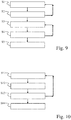
- FIGS. 7 and 8 One type of evaluation of the specific measures of correlation, which can be carried out as an alternative or in addition to the evaluation described above, is now based on FIGS. 7 and 8 described.
- the measure k of the correlation is shown for a large number of measuring points as a function of the distance D of the respective measuring point to another measuring point, in particular for each combination of measuring points.
- Fig. 7 shows such a connection for the in Fig. 2, Fig. 3 and Fig. 5 shown workpiece.
- Fig. 8 shows such a connection for the in Fig. 4 and Fig. 6 shown workpiece.
- the dependence k (D) of the correlation measure k on the distance D of the pairs of points can be graphically represented in addition to at least one cluster, in particular simultaneously, for example on different areas of the same screen or display or on screens or displays arranged next to one another.
- the representation can be changeable for a viewer in such a way that the viewer can establish a dependency k (D) in the by selecting (for example by clicking with a computer mouse) Representation achieved a highlighted representation of the associated measuring points in the cluster representation. This makes it easier to understand the relationships between the two representations and also makes it easier to draw conclusions. For example, if the dependencies k (D) in Fig. 8 a dependency is selected in the upper area, the corresponding points in the area 37 in FIG Fig. 6 highlighted.
- the viewer can thus easily see where the area with the high correlation is located in the workpiece.
- the cluster assigned to the pair of points can in particular also be highlighted. This is an advantage since there is generally more than one cluster in the type of representations accordingly FIGS. 5 and 6 is pictured.
Landscapes
- Physics & Mathematics (AREA)
- General Physics & Mathematics (AREA)
- Length Measuring Devices With Unspecified Measuring Means (AREA)
Priority Applications (2)
| Application Number | Priority Date | Filing Date | Title |
|---|---|---|---|
| EP19162769.4A EP3708945B1 (fr) | 2019-03-14 | 2019-03-14 | Évaluation des données de mesure d'une mesure d'une pluralité de pièces |
| US16/820,527 US11609089B2 (en) | 2019-03-14 | 2020-03-16 | System and method for analysis of measurement data acquired from multiple workpieces |
Applications Claiming Priority (1)
| Application Number | Priority Date | Filing Date | Title |
|---|---|---|---|
| EP19162769.4A EP3708945B1 (fr) | 2019-03-14 | 2019-03-14 | Évaluation des données de mesure d'une mesure d'une pluralité de pièces |
Publications (2)
| Publication Number | Publication Date |
|---|---|
| EP3708945A1 true EP3708945A1 (fr) | 2020-09-16 |
| EP3708945B1 EP3708945B1 (fr) | 2023-01-25 |
Family
ID=65812172
Family Applications (1)
| Application Number | Title | Priority Date | Filing Date |
|---|---|---|---|
| EP19162769.4A Active EP3708945B1 (fr) | 2019-03-14 | 2019-03-14 | Évaluation des données de mesure d'une mesure d'une pluralité de pièces |
Country Status (2)
| Country | Link |
|---|---|
| US (1) | US11609089B2 (fr) |
| EP (1) | EP3708945B1 (fr) |
Cited By (2)
| Publication number | Priority date | Publication date | Assignee | Title |
|---|---|---|---|---|
| DE102020211616B4 (de) | 2020-09-16 | 2021-08-12 | Carl Zeiss Industrielle Messtechnik Gmbh | Verfahren und Einrichtung zur Bewertung einer Messvorschrift zur Vermessung von Werkstücken |
| EP3913448A1 (fr) * | 2020-05-19 | 2021-11-24 | Carl Zeiss Industrielle Messtechnik GmbH | Procédé et agencement de mesure de pièces du même type |
Citations (2)
| Publication number | Priority date | Publication date | Assignee | Title |
|---|---|---|---|---|
| EP1679486A1 (fr) * | 2005-01-05 | 2006-07-12 | Mitutoyo Corporation | Procédé et programme d'estimation d'une incertitude des appareils de mesure |
| US20110054835A1 (en) * | 2009-08-25 | 2011-03-03 | Mitutoyo Corporation | Method of evaluating precision of output data using error propagation |
Family Cites Families (2)
| Publication number | Priority date | Publication date | Assignee | Title |
|---|---|---|---|---|
| US20170363403A1 (en) * | 2012-03-21 | 2017-12-21 | Renishaw Plc | Method and apparatus for inspecting workpieces |
| WO2016034855A1 (fr) * | 2014-09-02 | 2016-03-10 | Renishaw Plc | Appareil et procédé de mesure de coordonnées pour inspecter des pièces de fabrication, comprenant la génération de valeurs de correction de mesure à l'aide d'une forme de référence qui est connue pour ne pas s'éloigner sensiblement d'une forme parfaite |
-
2019
- 2019-03-14 EP EP19162769.4A patent/EP3708945B1/fr active Active
-
2020
- 2020-03-16 US US16/820,527 patent/US11609089B2/en active Active
Patent Citations (2)
| Publication number | Priority date | Publication date | Assignee | Title |
|---|---|---|---|---|
| EP1679486A1 (fr) * | 2005-01-05 | 2006-07-12 | Mitutoyo Corporation | Procédé et programme d'estimation d'une incertitude des appareils de mesure |
| US20110054835A1 (en) * | 2009-08-25 | 2011-03-03 | Mitutoyo Corporation | Method of evaluating precision of output data using error propagation |
Non-Patent Citations (1)
| Title |
|---|
| DANA EFSTATE ET AL: "Correlation of CMM Data with Flexible Fixturing", SAE TECHNICAL PAPER SERIES, vol. 1, 16 October 2001 (2001-10-16), US, XP055610604, ISSN: 0148-7191, DOI: 10.4271/2001-01-3066 * |
Cited By (2)
| Publication number | Priority date | Publication date | Assignee | Title |
|---|---|---|---|---|
| EP3913448A1 (fr) * | 2020-05-19 | 2021-11-24 | Carl Zeiss Industrielle Messtechnik GmbH | Procédé et agencement de mesure de pièces du même type |
| DE102020211616B4 (de) | 2020-09-16 | 2021-08-12 | Carl Zeiss Industrielle Messtechnik Gmbh | Verfahren und Einrichtung zur Bewertung einer Messvorschrift zur Vermessung von Werkstücken |
Also Published As
| Publication number | Publication date |
|---|---|
| EP3708945B1 (fr) | 2023-01-25 |
| US20200292309A1 (en) | 2020-09-17 |
| US11609089B2 (en) | 2023-03-21 |
Similar Documents
| Publication | Publication Date | Title |
|---|---|---|
| DE112016002090T5 (de) | Verfahren und system zur defektklassifizierung | |
| DE112012002680T5 (de) | Bearbeitungssimulationsvorrichtung und -verfahren | |
| EP3970113B1 (fr) | Détermination du niveau d'usure d'un outil | |
| EP1623287B1 (fr) | Conception d'outils et de processus pour technique de formage | |
| DE102020102406A1 (de) | Managementvorrichtung und managementsystem | |
| DE102020214959A1 (de) | Simulator, numerische Steuervorrichtung und Simulationsverfahren | |
| DE102017009429A1 (de) | Informationsverarbeitungsvorrichtung | |
| DE102016116523A1 (de) | Vibrationsanalysevorrichtung, die einen Zyklus der Werkzeugvibration in Bezug zum Werkstück berechnet | |
| DE102013008755A1 (de) | Offline-Programmiersystem | |
| DE102020104952A1 (de) | Verwaltungsvorrichtung und verwaltungssystem | |
| DE102016108991A1 (de) | Verfahren und Vorrichtung zur Charakterisierung eines Bauteils | |
| EP3708945B1 (fr) | Évaluation des données de mesure d'une mesure d'une pluralité de pièces | |
| DE112021004321T5 (de) | Informationsverarbeitungsvorrichtung, computerausführbares verfahren und computerlesbares speichermedium | |
| EP3835900B1 (fr) | Procédé et dispositif d'essai de pièces | |
| EP3913448B1 (fr) | Procédé et agencement de mesure de pièces du même type | |
| WO2005084844A1 (fr) | Procede de preparation de donnees de surface, procede et dispositif d'evaluation de qualite et de gestion de qualite d'un materiau en bande | |
| DE102020211616B4 (de) | Verfahren und Einrichtung zur Bewertung einer Messvorschrift zur Vermessung von Werkstücken | |
| DE102017221766A1 (de) | Bearbeitungsprogramm-analysevorrichtung, bearbeitungsprogramm-analyseprogramm und bearbeitungsprogramm-analyseverfahren | |
| EP3865979A1 (fr) | Procédé et dispositif d'aide à une planification basée sur un logiciel d'une mesure dimensionnelle | |
| DE10250285A1 (de) | Vorhersage des Termintreuegrads in der Serienfertigung | |
| DE102019212799A1 (de) | Abstandsbildanzeigevorrichtung und Abstandsbildanzeigeverfahren | |
| EP4130656B1 (fr) | Préparation d'échantillons de valeurs mesurées à partir d'une mesure d'une pluralité de pièces par un ou plusieurs appareils de mesure de coordonnées | |
| EP3722740A1 (fr) | Procédé et dispositif informatique permettant de sélectionner une séquence de mesure pour un appareil de mesure de coordonnées | |
| DE112021008104T5 (de) | Bearbeitungsformmodell-Vergleichsvorrichtung und numerisch gesteuertes Maschinensystem | |
| EP3848767B1 (fr) | Procédé de contrôle qualité de pièces ainsi qu'appareil de mesure de coordonnées et programme informatique |
Legal Events
| Date | Code | Title | Description |
|---|---|---|---|
| PUAI | Public reference made under article 153(3) epc to a published international application that has entered the european phase |
Free format text: ORIGINAL CODE: 0009012 |
|
| STAA | Information on the status of an ep patent application or granted ep patent |
Free format text: STATUS: REQUEST FOR EXAMINATION WAS MADE |
|
| 17P | Request for examination filed |
Effective date: 20200715 |
|
| AK | Designated contracting states |
Kind code of ref document: A1 Designated state(s): AL AT BE BG CH CY CZ DE DK EE ES FI FR GB GR HR HU IE IS IT LI LT LU LV MC MK MT NL NO PL PT RO RS SE SI SK SM TR |
|
| AX | Request for extension of the european patent |
Extension state: BA ME |
|
| STAA | Information on the status of an ep patent application or granted ep patent |
Free format text: STATUS: EXAMINATION IS IN PROGRESS |
|
| 17Q | First examination report despatched |
Effective date: 20210708 |
|
| RIN1 | Information on inventor provided before grant (corrected) |
Inventor name: GOERSCH, DANIEL Inventor name: RUEGER, OLIVER |
|
| REG | Reference to a national code |
Ref country code: DE Ref legal event code: R079 Ref document number: 502019006853 Country of ref document: DE Free format text: PREVIOUS MAIN CLASS: G01B0011000000 Ipc: G01B0021040000 |
|
| GRAP | Despatch of communication of intention to grant a patent |
Free format text: ORIGINAL CODE: EPIDOSNIGR1 |
|
| STAA | Information on the status of an ep patent application or granted ep patent |
Free format text: STATUS: GRANT OF PATENT IS INTENDED |
|
| RIC1 | Information provided on ipc code assigned before grant |
Ipc: G01B 21/04 20060101AFI20220930BHEP |
|
| INTG | Intention to grant announced |
Effective date: 20221018 |
|
| GRAS | Grant fee paid |
Free format text: ORIGINAL CODE: EPIDOSNIGR3 |
|
| GRAA | (expected) grant |
Free format text: ORIGINAL CODE: 0009210 |
|
| STAA | Information on the status of an ep patent application or granted ep patent |
Free format text: STATUS: THE PATENT HAS BEEN GRANTED |
|
| AK | Designated contracting states |
Kind code of ref document: B1 Designated state(s): AL AT BE BG CH CY CZ DE DK EE ES FI FR GB GR HR HU IE IS IT LI LT LU LV MC MK MT NL NO PL PT RO RS SE SI SK SM TR |
|
| REG | Reference to a national code |
Ref country code: GB Ref legal event code: FG4D Free format text: NOT ENGLISH |
|
| REG | Reference to a national code |
Ref country code: CH Ref legal event code: EP |
|
| REG | Reference to a national code |
Ref country code: DE Ref legal event code: R096 Ref document number: 502019006853 Country of ref document: DE |
|
| REG | Reference to a national code |
Ref country code: AT Ref legal event code: REF Ref document number: 1546183 Country of ref document: AT Kind code of ref document: T Effective date: 20230215 Ref country code: IE Ref legal event code: FG4D Free format text: LANGUAGE OF EP DOCUMENT: GERMAN |
|
| REG | Reference to a national code |
Ref country code: LT Ref legal event code: MG9D |
|
| REG | Reference to a national code |
Ref country code: NL Ref legal event code: MP Effective date: 20230125 |
|
| PG25 | Lapsed in a contracting state [announced via postgrant information from national office to epo] |
Ref country code: NL Free format text: LAPSE BECAUSE OF FAILURE TO SUBMIT A TRANSLATION OF THE DESCRIPTION OR TO PAY THE FEE WITHIN THE PRESCRIBED TIME-LIMIT Effective date: 20230125 |
|
| P01 | Opt-out of the competence of the unified patent court (upc) registered |
Effective date: 20230525 |
|
| PG25 | Lapsed in a contracting state [announced via postgrant information from national office to epo] |
Ref country code: RS Free format text: LAPSE BECAUSE OF FAILURE TO SUBMIT A TRANSLATION OF THE DESCRIPTION OR TO PAY THE FEE WITHIN THE PRESCRIBED TIME-LIMIT Effective date: 20230125 Ref country code: PT Free format text: LAPSE BECAUSE OF FAILURE TO SUBMIT A TRANSLATION OF THE DESCRIPTION OR TO PAY THE FEE WITHIN THE PRESCRIBED TIME-LIMIT Effective date: 20230525 Ref country code: NO Free format text: LAPSE BECAUSE OF FAILURE TO SUBMIT A TRANSLATION OF THE DESCRIPTION OR TO PAY THE FEE WITHIN THE PRESCRIBED TIME-LIMIT Effective date: 20230425 Ref country code: LV Free format text: LAPSE BECAUSE OF FAILURE TO SUBMIT A TRANSLATION OF THE DESCRIPTION OR TO PAY THE FEE WITHIN THE PRESCRIBED TIME-LIMIT Effective date: 20230125 Ref country code: LT Free format text: LAPSE BECAUSE OF FAILURE TO SUBMIT A TRANSLATION OF THE DESCRIPTION OR TO PAY THE FEE WITHIN THE PRESCRIBED TIME-LIMIT Effective date: 20230125 Ref country code: HR Free format text: LAPSE BECAUSE OF FAILURE TO SUBMIT A TRANSLATION OF THE DESCRIPTION OR TO PAY THE FEE WITHIN THE PRESCRIBED TIME-LIMIT Effective date: 20230125 Ref country code: ES Free format text: LAPSE BECAUSE OF FAILURE TO SUBMIT A TRANSLATION OF THE DESCRIPTION OR TO PAY THE FEE WITHIN THE PRESCRIBED TIME-LIMIT Effective date: 20230125 |
|
| PG25 | Lapsed in a contracting state [announced via postgrant information from national office to epo] |
Ref country code: SE Free format text: LAPSE BECAUSE OF FAILURE TO SUBMIT A TRANSLATION OF THE DESCRIPTION OR TO PAY THE FEE WITHIN THE PRESCRIBED TIME-LIMIT Effective date: 20230125 Ref country code: PL Free format text: LAPSE BECAUSE OF FAILURE TO SUBMIT A TRANSLATION OF THE DESCRIPTION OR TO PAY THE FEE WITHIN THE PRESCRIBED TIME-LIMIT Effective date: 20230125 Ref country code: IS Free format text: LAPSE BECAUSE OF FAILURE TO SUBMIT A TRANSLATION OF THE DESCRIPTION OR TO PAY THE FEE WITHIN THE PRESCRIBED TIME-LIMIT Effective date: 20230525 Ref country code: GR Free format text: LAPSE BECAUSE OF FAILURE TO SUBMIT A TRANSLATION OF THE DESCRIPTION OR TO PAY THE FEE WITHIN THE PRESCRIBED TIME-LIMIT Effective date: 20230426 Ref country code: FI Free format text: LAPSE BECAUSE OF FAILURE TO SUBMIT A TRANSLATION OF THE DESCRIPTION OR TO PAY THE FEE WITHIN THE PRESCRIBED TIME-LIMIT Effective date: 20230125 |
|
| REG | Reference to a national code |
Ref country code: DE Ref legal event code: R097 Ref document number: 502019006853 Country of ref document: DE |
|
| PG25 | Lapsed in a contracting state [announced via postgrant information from national office to epo] |
Ref country code: SM Free format text: LAPSE BECAUSE OF FAILURE TO SUBMIT A TRANSLATION OF THE DESCRIPTION OR TO PAY THE FEE WITHIN THE PRESCRIBED TIME-LIMIT Effective date: 20230125 Ref country code: RO Free format text: LAPSE BECAUSE OF FAILURE TO SUBMIT A TRANSLATION OF THE DESCRIPTION OR TO PAY THE FEE WITHIN THE PRESCRIBED TIME-LIMIT Effective date: 20230125 Ref country code: MC Free format text: LAPSE BECAUSE OF FAILURE TO SUBMIT A TRANSLATION OF THE DESCRIPTION OR TO PAY THE FEE WITHIN THE PRESCRIBED TIME-LIMIT Effective date: 20230125 Ref country code: EE Free format text: LAPSE BECAUSE OF FAILURE TO SUBMIT A TRANSLATION OF THE DESCRIPTION OR TO PAY THE FEE WITHIN THE PRESCRIBED TIME-LIMIT Effective date: 20230125 Ref country code: DK Free format text: LAPSE BECAUSE OF FAILURE TO SUBMIT A TRANSLATION OF THE DESCRIPTION OR TO PAY THE FEE WITHIN THE PRESCRIBED TIME-LIMIT Effective date: 20230125 Ref country code: CZ Free format text: LAPSE BECAUSE OF FAILURE TO SUBMIT A TRANSLATION OF THE DESCRIPTION OR TO PAY THE FEE WITHIN THE PRESCRIBED TIME-LIMIT Effective date: 20230125 |
|
| REG | Reference to a national code |
Ref country code: CH Ref legal event code: PL |
|
| PG25 | Lapsed in a contracting state [announced via postgrant information from national office to epo] |
Ref country code: SK Free format text: LAPSE BECAUSE OF FAILURE TO SUBMIT A TRANSLATION OF THE DESCRIPTION OR TO PAY THE FEE WITHIN THE PRESCRIBED TIME-LIMIT Effective date: 20230125 |
|
| REG | Reference to a national code |
Ref country code: BE Ref legal event code: MM Effective date: 20230331 |
|
| PLBE | No opposition filed within time limit |
Free format text: ORIGINAL CODE: 0009261 |
|
| STAA | Information on the status of an ep patent application or granted ep patent |
Free format text: STATUS: NO OPPOSITION FILED WITHIN TIME LIMIT |
|
| GBPC | Gb: european patent ceased through non-payment of renewal fee |
Effective date: 20230425 |
|
| PG25 | Lapsed in a contracting state [announced via postgrant information from national office to epo] |
Ref country code: LU Free format text: LAPSE BECAUSE OF NON-PAYMENT OF DUE FEES Effective date: 20230314 |
|
| 26N | No opposition filed |
Effective date: 20231026 |
|
| REG | Reference to a national code |
Ref country code: IE Ref legal event code: MM4A |
|
| PG25 | Lapsed in a contracting state [announced via postgrant information from national office to epo] |
Ref country code: GB Free format text: LAPSE BECAUSE OF NON-PAYMENT OF DUE FEES Effective date: 20230425 |
|
| PG25 | Lapsed in a contracting state [announced via postgrant information from national office to epo] |
Ref country code: SI Free format text: LAPSE BECAUSE OF FAILURE TO SUBMIT A TRANSLATION OF THE DESCRIPTION OR TO PAY THE FEE WITHIN THE PRESCRIBED TIME-LIMIT Effective date: 20230125 Ref country code: LI Free format text: LAPSE BECAUSE OF NON-PAYMENT OF DUE FEES Effective date: 20230331 Ref country code: IE Free format text: LAPSE BECAUSE OF NON-PAYMENT OF DUE FEES Effective date: 20230314 Ref country code: GB Free format text: LAPSE BECAUSE OF NON-PAYMENT OF DUE FEES Effective date: 20230425 Ref country code: FR Free format text: LAPSE BECAUSE OF NON-PAYMENT OF DUE FEES Effective date: 20230325 Ref country code: CH Free format text: LAPSE BECAUSE OF NON-PAYMENT OF DUE FEES Effective date: 20230331 |
|
| PG25 | Lapsed in a contracting state [announced via postgrant information from national office to epo] |
Ref country code: BE Free format text: LAPSE BECAUSE OF NON-PAYMENT OF DUE FEES Effective date: 20230331 |
|
| PGFP | Annual fee paid to national office [announced via postgrant information from national office to epo] |
Ref country code: DE Payment date: 20240320 Year of fee payment: 6 |
|
| PG25 | Lapsed in a contracting state [announced via postgrant information from national office to epo] |
Ref country code: IT Free format text: LAPSE BECAUSE OF FAILURE TO SUBMIT A TRANSLATION OF THE DESCRIPTION OR TO PAY THE FEE WITHIN THE PRESCRIBED TIME-LIMIT Effective date: 20230125 |