EP3708852A1 - Ejector and refrigerating system - Google Patents
Ejector and refrigerating system Download PDFInfo
- Publication number
- EP3708852A1 EP3708852A1 EP20162527.4A EP20162527A EP3708852A1 EP 3708852 A1 EP3708852 A1 EP 3708852A1 EP 20162527 A EP20162527 A EP 20162527A EP 3708852 A1 EP3708852 A1 EP 3708852A1
- Authority
- EP
- European Patent Office
- Prior art keywords
- valve
- fluid passage
- suction
- ejector
- pressure fluid
- Prior art date
- Legal status (The legal status is an assumption and is not a legal conclusion. Google has not performed a legal analysis and makes no representation as to the accuracy of the status listed.)
- Granted
Links
Images
Classifications
-
- F—MECHANICAL ENGINEERING; LIGHTING; HEATING; WEAPONS; BLASTING
- F25—REFRIGERATION OR COOLING; COMBINED HEATING AND REFRIGERATION SYSTEMS; HEAT PUMP SYSTEMS; MANUFACTURE OR STORAGE OF ICE; LIQUEFACTION SOLIDIFICATION OF GASES
- F25B—REFRIGERATION MACHINES, PLANTS OR SYSTEMS; COMBINED HEATING AND REFRIGERATION SYSTEMS; HEAT PUMP SYSTEMS
- F25B9/00—Compression machines, plants or systems, in which the refrigerant is air or other gas of low boiling point
- F25B9/08—Compression machines, plants or systems, in which the refrigerant is air or other gas of low boiling point using ejectors
-
- F—MECHANICAL ENGINEERING; LIGHTING; HEATING; WEAPONS; BLASTING
- F04—POSITIVE - DISPLACEMENT MACHINES FOR LIQUIDS; PUMPS FOR LIQUIDS OR ELASTIC FLUIDS
- F04F—PUMPING OF FLUID BY DIRECT CONTACT OF ANOTHER FLUID OR BY USING INERTIA OF FLUID TO BE PUMPED; SIPHONS
- F04F5/00—Jet pumps, i.e. devices in which flow is induced by pressure drop caused by velocity of another fluid flow
- F04F5/44—Component parts, details, or accessories not provided for in, or of interest apart from, groups F04F5/02 - F04F5/42
- F04F5/46—Arrangements of nozzles
-
- F—MECHANICAL ENGINEERING; LIGHTING; HEATING; WEAPONS; BLASTING
- F04—POSITIVE - DISPLACEMENT MACHINES FOR LIQUIDS; PUMPS FOR LIQUIDS OR ELASTIC FLUIDS
- F04F—PUMPING OF FLUID BY DIRECT CONTACT OF ANOTHER FLUID OR BY USING INERTIA OF FLUID TO BE PUMPED; SIPHONS
- F04F5/00—Jet pumps, i.e. devices in which flow is induced by pressure drop caused by velocity of another fluid flow
- F04F5/02—Jet pumps, i.e. devices in which flow is induced by pressure drop caused by velocity of another fluid flow the inducing fluid being liquid
- F04F5/04—Jet pumps, i.e. devices in which flow is induced by pressure drop caused by velocity of another fluid flow the inducing fluid being liquid displacing elastic fluids
-
- F—MECHANICAL ENGINEERING; LIGHTING; HEATING; WEAPONS; BLASTING
- F04—POSITIVE - DISPLACEMENT MACHINES FOR LIQUIDS; PUMPS FOR LIQUIDS OR ELASTIC FLUIDS
- F04F—PUMPING OF FLUID BY DIRECT CONTACT OF ANOTHER FLUID OR BY USING INERTIA OF FLUID TO BE PUMPED; SIPHONS
- F04F5/00—Jet pumps, i.e. devices in which flow is induced by pressure drop caused by velocity of another fluid flow
- F04F5/14—Jet pumps, i.e. devices in which flow is induced by pressure drop caused by velocity of another fluid flow the inducing fluid being elastic fluid
- F04F5/16—Jet pumps, i.e. devices in which flow is induced by pressure drop caused by velocity of another fluid flow the inducing fluid being elastic fluid displacing elastic fluids
-
- F—MECHANICAL ENGINEERING; LIGHTING; HEATING; WEAPONS; BLASTING
- F04—POSITIVE - DISPLACEMENT MACHINES FOR LIQUIDS; PUMPS FOR LIQUIDS OR ELASTIC FLUIDS
- F04F—PUMPING OF FLUID BY DIRECT CONTACT OF ANOTHER FLUID OR BY USING INERTIA OF FLUID TO BE PUMPED; SIPHONS
- F04F5/00—Jet pumps, i.e. devices in which flow is induced by pressure drop caused by velocity of another fluid flow
- F04F5/44—Component parts, details, or accessories not provided for in, or of interest apart from, groups F04F5/02 - F04F5/42
- F04F5/46—Arrangements of nozzles
- F04F5/461—Adjustable nozzles
-
- F—MECHANICAL ENGINEERING; LIGHTING; HEATING; WEAPONS; BLASTING
- F04—POSITIVE - DISPLACEMENT MACHINES FOR LIQUIDS; PUMPS FOR LIQUIDS OR ELASTIC FLUIDS
- F04F—PUMPING OF FLUID BY DIRECT CONTACT OF ANOTHER FLUID OR BY USING INERTIA OF FLUID TO BE PUMPED; SIPHONS
- F04F5/00—Jet pumps, i.e. devices in which flow is induced by pressure drop caused by velocity of another fluid flow
- F04F5/44—Component parts, details, or accessories not provided for in, or of interest apart from, groups F04F5/02 - F04F5/42
- F04F5/46—Arrangements of nozzles
- F04F5/463—Arrangements of nozzles with provisions for mixing
-
- F—MECHANICAL ENGINEERING; LIGHTING; HEATING; WEAPONS; BLASTING
- F04—POSITIVE - DISPLACEMENT MACHINES FOR LIQUIDS; PUMPS FOR LIQUIDS OR ELASTIC FLUIDS
- F04F—PUMPING OF FLUID BY DIRECT CONTACT OF ANOTHER FLUID OR BY USING INERTIA OF FLUID TO BE PUMPED; SIPHONS
- F04F5/00—Jet pumps, i.e. devices in which flow is induced by pressure drop caused by velocity of another fluid flow
- F04F5/44—Component parts, details, or accessories not provided for in, or of interest apart from, groups F04F5/02 - F04F5/42
- F04F5/48—Control
- F04F5/52—Control of evacuating pumps
-
- F—MECHANICAL ENGINEERING; LIGHTING; HEATING; WEAPONS; BLASTING
- F25—REFRIGERATION OR COOLING; COMBINED HEATING AND REFRIGERATION SYSTEMS; HEAT PUMP SYSTEMS; MANUFACTURE OR STORAGE OF ICE; LIQUEFACTION SOLIDIFICATION OF GASES
- F25B—REFRIGERATION MACHINES, PLANTS OR SYSTEMS; COMBINED HEATING AND REFRIGERATION SYSTEMS; HEAT PUMP SYSTEMS
- F25B41/00—Fluid-circulation arrangements
- F25B41/30—Expansion means; Dispositions thereof
-
- F—MECHANICAL ENGINEERING; LIGHTING; HEATING; WEAPONS; BLASTING
- F25—REFRIGERATION OR COOLING; COMBINED HEATING AND REFRIGERATION SYSTEMS; HEAT PUMP SYSTEMS; MANUFACTURE OR STORAGE OF ICE; LIQUEFACTION SOLIDIFICATION OF GASES
- F25B—REFRIGERATION MACHINES, PLANTS OR SYSTEMS; COMBINED HEATING AND REFRIGERATION SYSTEMS; HEAT PUMP SYSTEMS
- F25B5/00—Compression machines, plants or systems, with several evaporator circuits, e.g. for varying refrigerating capacity
- F25B5/02—Compression machines, plants or systems, with several evaporator circuits, e.g. for varying refrigerating capacity arranged in parallel
-
- F—MECHANICAL ENGINEERING; LIGHTING; HEATING; WEAPONS; BLASTING
- F04—POSITIVE - DISPLACEMENT MACHINES FOR LIQUIDS; PUMPS FOR LIQUIDS OR ELASTIC FLUIDS
- F04F—PUMPING OF FLUID BY DIRECT CONTACT OF ANOTHER FLUID OR BY USING INERTIA OF FLUID TO BE PUMPED; SIPHONS
- F04F5/00—Jet pumps, i.e. devices in which flow is induced by pressure drop caused by velocity of another fluid flow
- F04F5/54—Installations characterised by use of jet pumps, e.g. combinations of two or more jet pumps of different type
-
- F—MECHANICAL ENGINEERING; LIGHTING; HEATING; WEAPONS; BLASTING
- F25—REFRIGERATION OR COOLING; COMBINED HEATING AND REFRIGERATION SYSTEMS; HEAT PUMP SYSTEMS; MANUFACTURE OR STORAGE OF ICE; LIQUEFACTION SOLIDIFICATION OF GASES
- F25B—REFRIGERATION MACHINES, PLANTS OR SYSTEMS; COMBINED HEATING AND REFRIGERATION SYSTEMS; HEAT PUMP SYSTEMS
- F25B2341/00—Details of ejectors not being used as compression device; Details of flow restrictors or expansion valves
- F25B2341/001—Ejectors not being used as compression device
- F25B2341/0012—Ejectors with the cooled primary flow at high pressure
-
- F—MECHANICAL ENGINEERING; LIGHTING; HEATING; WEAPONS; BLASTING
- F25—REFRIGERATION OR COOLING; COMBINED HEATING AND REFRIGERATION SYSTEMS; HEAT PUMP SYSTEMS; MANUFACTURE OR STORAGE OF ICE; LIQUEFACTION SOLIDIFICATION OF GASES
- F25B—REFRIGERATION MACHINES, PLANTS OR SYSTEMS; COMBINED HEATING AND REFRIGERATION SYSTEMS; HEAT PUMP SYSTEMS
- F25B2341/00—Details of ejectors not being used as compression device; Details of flow restrictors or expansion valves
- F25B2341/001—Ejectors not being used as compression device
- F25B2341/0015—Ejectors not being used as compression device using two or more ejectors
-
- F—MECHANICAL ENGINEERING; LIGHTING; HEATING; WEAPONS; BLASTING
- F25—REFRIGERATION OR COOLING; COMBINED HEATING AND REFRIGERATION SYSTEMS; HEAT PUMP SYSTEMS; MANUFACTURE OR STORAGE OF ICE; LIQUEFACTION SOLIDIFICATION OF GASES
- F25B—REFRIGERATION MACHINES, PLANTS OR SYSTEMS; COMBINED HEATING AND REFRIGERATION SYSTEMS; HEAT PUMP SYSTEMS
- F25B2400/00—Component parts or details not otherwise provided for in this subclass
- F25B2400/23—Separators
Definitions
- the present invention relates to a refrigeration system, and more particularly, the present invention relates to a refrigeration system with an ejector.
- an ejector In commercial refrigeration systems, especially systems that require a large pressure differential, an ejector is used to improve efficiency.
- the ejector typically pressurizes a suction fluid by means of a high-pressure fluid and supplies mixed fluids to a compressor inlet, thereby increasing the pressure of fluid at the compressor inlet, reducing the requirements on the capacity of the compressor and improving the efficiency of the system.
- a significant loss of compressor efficiency will be caused.
- An object of at least some embodiments of the present invention is to solve or at least alleviate problems existing in the related art.
- an ejector for use in a refrigeration system which includes:
- a second valve is disposed in the high-pressure fluid passage, and the second valve is mechanically connected to the first valve so that it is opened or closed in synchronization with the first valve.
- the high-pressure fluid passage and the suction fluid passage include parallel sections that are parallel to each other, and the first valve and the second valve are respectively disposed in the parallel sections of the suction fluid passage and the high-pressure fluid passage.
- the elastic diaphragm is connected to a front side of a spool of the first valve, and a back side of the spool of the first valve is supported by a first elastic member;
- the first elastic member is connected to a housing of the ejector by a first bolt, and the first bolt is configured to adjust an initial position of the spool of the first valve so that a superheat degree of the suction fluid can for example be adjusted.
- the spool of the first valve is connected to a spool of the second valve through a connecting rod, and a back side of the spool of the second valve is supported by a second elastic member; the second elastic member is connected to the housing of the ejector by a second bolt, and the second bolt is configured to adjust an initial position of the spool of the second valve.
- the high-pressure fluid passage includes a high-pressure fluid nozzle
- the suction fluid passage includes a suction chamber surrounding the high-pressure fluid nozzle
- the thermal bulb is disposed in the suction chamber or at a position near an inlet of the suction chamber.
- the high-pressure fluid nozzle includes a constricted section, a throat portion, and a diffusion section in sequence, and the high-pressure fluid nozzle further includes a needle valve at the throat portion.
- the mixing chamber includes a constricted section, a neck section, and a diffusion section in sequence.
- a fluid in the closed cavity is a saturated refrigerant having substantially the same composition as the suction fluid.
- the thermal bulb is arranged in or outside the suction fluid passage, and the thermal bulb is in communication with the closed cavity via a conduit.
- a refrigeration system is further provided, which includes the ejector according to various embodiments.
- the refrigeration system includes a single ejector or a plurality of ejectors connected in parallel.
- the high-pressure fluid inlet of the ejector is connected to an outlet of a compressor via an optional regenerator, and a heat exchanger, the suction fluid inlet of the ejector is connected to an evaporator, and an outlet of the ejector is connected to a separator.
- the refrigeration system includes:
- the liquid-phase outlet of the gas-liquid separator is further connected to an inlet of a low-temperature compressor via a low-temperature expansion valve and a low-temperature evaporator, and an outlet of the low-temperature compressor is connected to the inlet of the medium-temperature compressor.
- orientation terms as “upper”, “lower”, “left”, “right”, “front”, “rear”, “front side”, “back side”, “top”, “bottom” or the like that are mentioned or may be mentioned in this description are defined with respect to the configurations shown in the individual drawings. They are relative concepts and thus possibly vary according to their different locations or different states of use. Therefore, these or other orientation terms shall not be interpreted as limiting terms.
- the ejector includes: a high-pressure fluid passage 1 extending from a high-pressure fluid inlet 11 to a mixing chamber 8; a suction fluid passage 2 extending from a suction fluid inlet 21 to the mixing chamber 8, a first valve being disposed in the suction fluid passage 2; the mixing chamber 8, which includes a mixed fluid outlet 84; and a thermal bulb 75 arranged downstream of the first valve in the suction fluid passage 2; wherein an elastic diaphragm 47 is disposed in the suction fluid passage 2, the suction fluid passage 2 is on a first side of the elastic diaphragm 47, and a closed cavity 73 is on a second side of the elastic diaphragm 47; the thermal bulb 75 is in communication with the closed cavity 73, and the thermal bulb 75 and the closed cavity 73 are filled with fluid; and the elastic diaphragm 47 is associated with the first valve so that the first valve is opened or closed in response to a change in
- the high-pressure fluid passage 1 is configured to receive a fluid MF having a higher pressure, such as a 90bar (9x10 6 Pa) refrigerant fluid, from an outlet of a compressor for example.
- the fluid MF will be further accelerated when passing through the high-pressure fluid passage 1, whereby a fluid at the suction fluid inlet 21 is suctioned and mixed with the fluid MF.
- the high-pressure fluid passage 1 may include a high-pressure fluid inlet 11, a first section 12, a second section 13, and a high-pressure fluid nozzle 14 in sequence.
- the second section 13 may be perpendicular to the first section 12.
- the high-pressure fluid nozzle 14 may include a constricted section 141 having a gradually decreasing cross-sectional area, a throat portion 142 having a minimum cross-sectional area, and a diffusion section 143 having a gradually increasing cross-sectional area.
- the high-pressure fluid nozzle 14 may further include a needle valve 5 at the throat portion 142, and the needle valve 5 may be operated by, for example, a stepper motor to control the flow of the high-pressure fluid ejected from the nozzle.
- the high-pressure fluid passage 1 may have any other suitable structure.
- the high-pressure fluid nozzle 14 may have other suitable structures. The high-pressure fluid is accelerated after passing through the nozzle, for example to a supersonic speed.
- the suction fluid passage 2 is configured to receive a suction fluid SF having a lower pressure, such as 30bar (3x10 6 Pa), from an outlet of an evaporator for example.
- the suction fluid passage 2 may include a suction fluid inlet 21, a first section 22, a second section 23, a third section 24, and a suction chamber 25.
- the second section 23 may be perpendicular to the first section 22, and the third section 24 may be perpendicular to the second section 23.
- the suction fluid passage 2 may have any suitable structure.
- the suction chamber 25 surrounds the high-pressure fluid nozzle 14.
- the high-pressure fluid MF and the suction fluid SF are mixed after entering the mixing chamber 8, and the mixing chamber 8 may, for example, include a constricted section 81 having a gradually decreasing cross-sectional area, a neck section 82 having a substantially constant cross-sectional area, a diffusion section 83 having a gradually increasing cross-sectional area and an outlet 84 of mixed fluids in sequence.
- the mixing chamber 8 may have other layouts.
- the mixed fluids EF exiting from the mixed fluid outlet 84 may have a higher pressure (such as 35bar (3.5x10 6 Pa)) than the suction fluid SF, and the mixed fluids EF may be provided to the inlet of the compressor, thereby supplying a fluid having a higher pressure to the compressor, and reducing the requirements on the capacity of the compressor.
- a higher pressure such as 35bar (3.5x10 6 Pa)
- a reverse flow RF from the mixing chamber 8 to the suction chamber 25 may be generated.
- This type of reverse flow usually occurs when the pressure outside the mixed fluid outlet is too high, for example, if the fluid pressures at the outlets of some ejectors are lower than other ejectors when a plurality of ejectors are connected in parallel, or if the downstream pressure is too high.
- the generation of the reverse current RF will lead to a reduction in system efficiency, damage the user experience, and even cause system shut-down.
- the reverse flow problem is solved by the first valve arranged in the suction fluid passage 2, the elastic diaphragm 47 associated with the first valve, the closed cavity 73 and the thermal bulb 75.
- the first valve may have a valve seat 44 and a spool 43.
- the thermal bulb 75 is arranged at a position downstream of the first valve in the suction fluid passage 2.
- the thermal bulb 75 is arranged at a position near the inlet of the suction chamber 25, where the suction chamber 25 is connected to the upstream pipe (i.e., the third section 24).
- the elastic diaphragm 47 is disposed in the suction fluid passage 2.
- the elastic diaphragm 47 is disposed at a distal end of the second section 23 of the suction fluid passage 2.
- the suction fluid passage 2 is on a first side of the elastic diaphragm 47, and the closed cavity 73 is on a second side of the elastic diaphragm 47. In fact, it may also be considered that a part of the suction fluid passage 2 is partitioned by the elastic diaphragm 47 so that the closed cavity 73 is formed.
- the thermal bulb 75 is in communication with the closed cavity 73, for example by means of a conduit 74, and the thermal bulb 75 and the closed cavity 73 are filled with fluid.
- the elastic diaphragm 47 is associated with the first valve, so that the first valve is opened or closed in response to a change in a pressure difference across two sides of the elastic diaphragm 47.
- the elastic diaphragm 47 is connected to a front side of the spool 43 of the first valve through a connecting rod 46 for example, and the spool 43 of the first valve, such as a back side of the spool 43, may be supported by a first elastic member 34.
- the first elastic member 34 is connected to the housing of the suction fluid passage 2 of the ejector by a first bolt 33.
- the first elastic member 34 and the connecting rod 46 may be located on the same side of the spool 43.
- any suitable mechanical structure may be used to associate the elastic diaphragm 47 with the first valve.
- the first bolt 33 can be configured to adjust an initial position of the spool 43 of the first valve, thereby adjusting the superheat degree of the suction fluid.
- the first elastic member 34 having an appropriate elastic coefficient may be selected and the initial position of the first bolt 33 may be set according to the characteristics of the fluid in the thermal bulb 75 and the closed cavity 73, thereby effectively preventing the reverse flow RF.
- a second valve may be disposed in the high-pressure fluid passage 1, and the second valve is mechanically connected to the first valve so that it is opened or closed in synchronization with the first valve.
- the second section 13 of the high-pressure fluid passage 1 and the second section 23 of the suction fluid passage 2 may be disposed in parallel, and the second valve and the first valve are respectively disposed in the second section 13 of the high-pressure fluid passage 1 and the second section 23 of the suction fluid passage 2.
- the second valve also includes a valve seat 42 and a spool 41. The spool 41 is supported by a second elastic member 32 and is mounted to the housing of the high-pressure fluid passage 1 through a second bolt 31.
- the second bolt 31 may be configured to adjust an initial position of the spool 41 of the second valve.
- the second valve is mechanically connected to the first valve, such as by a connecting rod 45 or by other suitable mechanical means. Therefore, in case of an occurrence of a reverse flow, the second valve in the high-pressure fluid passage is also closed in response to the closing of the first valve, thereby stopping entering of the high-pressure fluid into the ejector.
- the thermal bulb 75 is disposed in the third section 24 of the suction fluid passage 2 at a position close to the inlet of the suction chamber 25. It should be understood that in an alternative embodiment, the thermal bulb 75 may be disposed at any position downstream of the first valve of the suction fluid passage 2, such as at a position of the second section 23 of the suction fluid passage 2 downstream of the first valve, at the third section 24 or in the suction chamber 25. Disposing the thermal bulb 75 at the inlet of the suction chamber 25 enables the reverse flow RF to be sensed immediately, thereby improving the sensitivity of the device.
- the thermal bulb 75, the conduit 74, and the closed cavity 73 may be filled with any suitable fluid; for example, the fluid may be composed of a saturated refrigerant having the same or similar compositions as the fluid SF in the suction fluid passage 2.
- the thermal bulb 75 may include a saturated refrigerant and other compositions such as an inert gas.
- the thermal bulb 75 and the conduit 74 are arranged outside the suction fluid passage 2. In this case, the thermal bulb 75 and the conduit 74 may be appropriately wrapped and heat insulated.
- the thermal bulb 75 may be disposed in the suction fluid passage 2, and the conduit 74 may also be disposed in the suction fluid passage 2.
- the present invention also relates to a refrigeration system including the ejector according to various embodiments of the present invention.
- a refrigeration system will be described; for example, a commercial refrigerating cabinet is taken as an example.
- the refrigeration system may include a plurality of ejectors 941, 942 and 943 connected in parallel, and in an alternative embodiment, only one ejector may be provided.
- the high-pressure fluid inlet of each ejector is connected to outlets of compressors 911, 912 and 913, and a heat exchanger 921 and an optional regenerator 93 may be disposed therebetween.
- the heat exchanger 921 may be for example a condenser or an air cooler.
- the compressors 911, 912 and 913 may be medium-temperature compressors.
- the medium-temperature compressors 911, 912 and 913 are connected to the high-pressure fluid inlets of each ejector 941, 942 and 943 via the heat exchanger 921 and the optional regenerator 93.
- the regenerator 93 the fluid can exchange heat with a gas-phase fluid of a separator 95.
- the mixed fluid outlet of each ejector 941, 942 and 943 is in communication with the separator 95.
- the gas phase of the separator 95 leads to the inlets of the medium-temperature compressors 911, 912 and 913 through the optional regenerator 93, and the liquid phase of the separator 95 enters an evaporator 971 through an optional booster pump 961 or a bypass passage 962 and a medium-temperature expansion valve 963, and then enters the suction fluid inlet of each ejector 941, 942 and 943.
- a portion of the liquid-phase fluid of the gas-liquid separator 95 may also flow to inlets of low-temperature compressors 991 and 992 through a low-temperature expansion valve and a low-temperature evaporator 981, and outlets of the low-temperature compressors are connected to the inlets of the medium-temperature compressor 911, 912 and 913.
- the ejector according to various embodiments may also be applied to other types of refrigeration devices.
Landscapes
- Engineering & Computer Science (AREA)
- Physics & Mathematics (AREA)
- Mechanical Engineering (AREA)
- General Engineering & Computer Science (AREA)
- Fluid Mechanics (AREA)
- Thermal Sciences (AREA)
- Jet Pumps And Other Pumps (AREA)
Abstract
Description
- The present invention relates to a refrigeration system, and more particularly, the present invention relates to a refrigeration system with an ejector.
- In commercial refrigeration systems, especially systems that require a large pressure differential, an ejector is used to improve efficiency. The ejector typically pressurizes a suction fluid by means of a high-pressure fluid and supplies mixed fluids to a compressor inlet, thereby increasing the pressure of fluid at the compressor inlet, reducing the requirements on the capacity of the compressor and improving the efficiency of the system. During the operation of the ejector, if the high-pressure fluid and an outlet fluid flow reversely to an inlet of the suction fluid, a significant loss of compressor efficiency will be caused.
- An object of at least some embodiments of the present invention is to solve or at least alleviate problems existing in the related art.
- According to one aspect, an ejector for use in a refrigeration system is provided, which includes:
- a mixing chamber, which includes a mixed fluid outlet;
- a high-pressure fluid passage extending from a high-pressure fluid inlet to the mixing chamber;
- a suction fluid passage extending from a suction fluid inlet to the mixing chamber, a first valve being disposed in the suction fluid passage; and
- a thermal bulb arranged in the suction fluid passage downstream of the first valve;
- wherein an elastic diaphragm is disposed in the suction fluid passage, the suction fluid passage is on a first side of the elastic diaphragm, and a closed cavity is on a second side of the elastic diaphragm; the thermal bulb is in communication with the closed cavity, and the thermal bulb and the closed cavity are filled with fluid; and the elastic diaphragm is associated with the first valve so that the first valve is opened or closed in response to a change in a pressure difference across two sides of the elastic diaphragm.
- Optionally, in the ejector, a second valve is disposed in the high-pressure fluid passage, and the second valve is mechanically connected to the first valve so that it is opened or closed in synchronization with the first valve.
- Optionally, in the ejector, the high-pressure fluid passage and the suction fluid passage include parallel sections that are parallel to each other, and the first valve and the second valve are respectively disposed in the parallel sections of the suction fluid passage and the high-pressure fluid passage.
- Optionally, in the ejector, the elastic diaphragm is connected to a front side of a spool of the first valve, and a back side of the spool of the first valve is supported by a first elastic member; the first elastic member is connected to a housing of the ejector by a first bolt, and the first bolt is configured to adjust an initial position of the spool of the first valve so that a superheat degree of the suction fluid can for example be adjusted.
- Optionally, in the ejector, the spool of the first valve is connected to a spool of the second valve through a connecting rod, and a back side of the spool of the second valve is supported by a second elastic member; the second elastic member is connected to the housing of the ejector by a second bolt, and the second bolt is configured to adjust an initial position of the spool of the second valve.
- Optionally, in the ejector, the high-pressure fluid passage includes a high-pressure fluid nozzle, the suction fluid passage includes a suction chamber surrounding the high-pressure fluid nozzle, and the thermal bulb is disposed in the suction chamber or at a position near an inlet of the suction chamber.
- Optionally, in the ejector, the high-pressure fluid nozzle includes a constricted section, a throat portion, and a diffusion section in sequence, and the high-pressure fluid nozzle further includes a needle valve at the throat portion.
- Optionally, in the ejector, the mixing chamber includes a constricted section, a neck section, and a diffusion section in sequence.
- Optionally, in the ejector, a fluid in the closed cavity is a saturated refrigerant having substantially the same composition as the suction fluid.
- Optionally, in the ejector, the thermal bulb is arranged in or outside the suction fluid passage, and the thermal bulb is in communication with the closed cavity via a conduit.
- A refrigeration system is further provided, which includes the ejector according to various embodiments.
- Optionally, the refrigeration system includes a single ejector or a plurality of ejectors connected in parallel.
- Optionally, in the refrigeration system, the high-pressure fluid inlet of the ejector is connected to an outlet of a compressor via an optional regenerator, and a heat exchanger, the suction fluid inlet of the ejector is connected to an evaporator, and an outlet of the ejector is connected to a separator.
- Optionally, the refrigeration system includes:
- a medium-temperature compressor, an outlet of which is connected to the high-pressure fluid inlet of the ejector via the heat exchanger and the optional regenerator; and
- a gas-liquid separator, wherein mixed fluid outlets of the plurality of ejectors are connected to the gas-liquid separator, a gas-phase outlet of the gas-liquid separator is connected to an inlet of the medium-temperature compressor, and a liquid-phase outlet of the gas-liquid separator is connected to suction fluid inlets of the plurality of ejectors via a medium-temperature expansion valve and a medium-temperature evaporator.
- Optionally, in the refrigeration system, the liquid-phase outlet of the gas-liquid separator is further connected to an inlet of a low-temperature compressor via a low-temperature expansion valve and a low-temperature evaporator, and an outlet of the low-temperature compressor is connected to the inlet of the medium-temperature compressor.
- The present invention will become easier to understand with reference to the accompanying drawings. The drawings are merely used for illustration and are by way of example only, and are not intended to limit the scope of the claims. In addition, like parts are denoted by like numerals in the drawings, wherein:
-
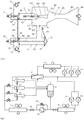
FIG. 1 is a schematic structural view of an ejector; and -
FIG. 2 is a schematic structural view of a refrigeration system to which the ejector is applied. - It will be readily understood that those skilled in the art can propose various alternative structural forms and implementations without departing from the scope of the claims. Therefore, the following specific embodiments and the accompanying drawings are merely exemplary descriptions of the present invention, which shall not be deemed as the entirety of the present invention or as limiting or restricting the scope of the claims.
- Such orientation terms as "upper", "lower", "left", "right", "front", "rear", "front side", "back side", "top", "bottom" or the like that are mentioned or may be mentioned in this description are defined with respect to the configurations shown in the individual drawings. They are relative concepts and thus possibly vary according to their different locations or different states of use. Therefore, these or other orientation terms shall not be interpreted as limiting terms.
- Referring first to
FIG. 1 , an internal structure of an ejector is shown. The ejector includes: a high-pressure fluid passage 1 extending from a high-pressure fluid inlet 11 to amixing chamber 8; asuction fluid passage 2 extending from asuction fluid inlet 21 to themixing chamber 8, a first valve being disposed in thesuction fluid passage 2; themixing chamber 8, which includes amixed fluid outlet 84; and athermal bulb 75 arranged downstream of the first valve in thesuction fluid passage 2; wherein anelastic diaphragm 47 is disposed in thesuction fluid passage 2, thesuction fluid passage 2 is on a first side of theelastic diaphragm 47, and a closedcavity 73 is on a second side of theelastic diaphragm 47; thethermal bulb 75 is in communication with the closedcavity 73, and thethermal bulb 75 and the closedcavity 73 are filled with fluid; and theelastic diaphragm 47 is associated with the first valve so that the first valve is opened or closed in response to a change in a pressure difference across two sides of theelastic diaphragm 47. An advantage of the ejector is that the entire anti-reverse flow system can be implemented by using a mechanical structure without external electronic control, and the anti-reverse flow system can automatically prevent a reverse flow and has a high stability. - The high-pressure fluid passage 1 is configured to receive a fluid MF having a higher pressure, such as a 90bar (9x10⁶Pa) refrigerant fluid, from an outlet of a compressor for example. The fluid MF will be further accelerated when passing through the high-pressure fluid passage 1, whereby a fluid at the
suction fluid inlet 21 is suctioned and mixed with the fluid MF. In the illustrated embodiment, the high-pressure fluid passage 1 may include a high-pressure fluid inlet 11, afirst section 12, asecond section 13, and a high-pressure fluid nozzle 14 in sequence. In some embodiments, thesecond section 13 may be perpendicular to thefirst section 12. In some embodiments, the high-pressure fluid nozzle 14 may include aconstricted section 141 having a gradually decreasing cross-sectional area, athroat portion 142 having a minimum cross-sectional area, and adiffusion section 143 having a gradually increasing cross-sectional area. The high-pressure fluid nozzle 14 may further include aneedle valve 5 at thethroat portion 142, and theneedle valve 5 may be operated by, for example, a stepper motor to control the flow of the high-pressure fluid ejected from the nozzle. In an alternative embodiment, the high-pressure fluid passage 1 may have any other suitable structure. In an alternative embodiment, the high-pressure fluid nozzle 14 may have other suitable structures. The high-pressure fluid is accelerated after passing through the nozzle, for example to a supersonic speed. - The
suction fluid passage 2 is configured to receive a suction fluid SF having a lower pressure, such as 30bar (3x10⁶Pa), from an outlet of an evaporator for example. In some embodiments, thesuction fluid passage 2 may include asuction fluid inlet 21, afirst section 22, asecond section 23, athird section 24, and asuction chamber 25. In some embodiments, thesecond section 23 may be perpendicular to thefirst section 22, and thethird section 24 may be perpendicular to thesecond section 23. In an alternative embodiment, thesuction fluid passage 2 may have any suitable structure. In the illustrated embodiment, thesuction chamber 25 surrounds the high-pressure fluid nozzle 14. In some embodiments, the high-pressure fluid MF and the suction fluid SF are mixed after entering themixing chamber 8, and themixing chamber 8 may, for example, include aconstricted section 81 having a gradually decreasing cross-sectional area, aneck section 82 having a substantially constant cross-sectional area, adiffusion section 83 having a gradually increasing cross-sectional area and anoutlet 84 of mixed fluids in sequence. In an alternative embodiment, themixing chamber 8 may have other layouts. The mixed fluids EF exiting from the mixedfluid outlet 84 may have a higher pressure (such as 35bar (3.5x10⁶Pa)) than the suction fluid SF, and the mixed fluids EF may be provided to the inlet of the compressor, thereby supplying a fluid having a higher pressure to the compressor, and reducing the requirements on the capacity of the compressor. - When this type of ejector is operating, if the fluid cannot exit from the mixed
fluid outlet 84 due to the low pressure at the suction fluid, a reverse flow RF from themixing chamber 8 to thesuction chamber 25 may be generated. This type of reverse flow usually occurs when the pressure outside the mixed fluid outlet is too high, for example, if the fluid pressures at the outlets of some ejectors are lower than other ejectors when a plurality of ejectors are connected in parallel, or if the downstream pressure is too high. The generation of the reverse current RF will lead to a reduction in system efficiency, damage the user experience, and even cause system shut-down. - The reverse flow problem is solved by the first valve arranged in the
suction fluid passage 2, theelastic diaphragm 47 associated with the first valve, theclosed cavity 73 and thethermal bulb 75. Specifically, the first valve may have avalve seat 44 and aspool 43. Thethermal bulb 75 is arranged at a position downstream of the first valve in thesuction fluid passage 2. For example, in the illustrated embodiment, thethermal bulb 75 is arranged at a position near the inlet of thesuction chamber 25, where thesuction chamber 25 is connected to the upstream pipe (i.e., the third section 24). Theelastic diaphragm 47 is disposed in thesuction fluid passage 2. In this embodiment, theelastic diaphragm 47 is disposed at a distal end of thesecond section 23 of thesuction fluid passage 2. Thesuction fluid passage 2 is on a first side of theelastic diaphragm 47, and theclosed cavity 73 is on a second side of theelastic diaphragm 47. In fact, it may also be considered that a part of thesuction fluid passage 2 is partitioned by theelastic diaphragm 47 so that theclosed cavity 73 is formed. Thethermal bulb 75 is in communication with theclosed cavity 73, for example by means of aconduit 74, and thethermal bulb 75 and theclosed cavity 73 are filled with fluid. Theelastic diaphragm 47 is associated with the first valve, so that the first valve is opened or closed in response to a change in a pressure difference across two sides of theelastic diaphragm 47. When a reverse flow RF occurs at the position of thethermal bulb 75, due to the existence of the two-phase refrigerant, a superheat degree of the refrigerant at thethermal bulb 75 will decrease, and a difference in the pressure of the fluid in thethermal bulb 75 and theclosed cavity 73 and that of the fluid in thesecond section 23 of thesuction fluid passage 2 will decrease, so theelastic diaphragm 47 will move to the right in the figure. Since thespool 43 is associated with theelastic diaphragm 47, thespool 43 will also move to close the first valve, thereby suppressing the reverse flow RF. In the illustrated embodiment, theelastic diaphragm 47 is connected to a front side of thespool 43 of the first valve through a connectingrod 46 for example, and thespool 43 of the first valve, such as a back side of thespool 43, may be supported by a firstelastic member 34. The firstelastic member 34 is connected to the housing of thesuction fluid passage 2 of the ejector by afirst bolt 33. Alternatively, the firstelastic member 34 and the connectingrod 46 may be located on the same side of thespool 43. In addition, in an alternative embodiment, any suitable mechanical structure may be used to associate theelastic diaphragm 47 with the first valve. Thefirst bolt 33 can be configured to adjust an initial position of thespool 43 of the first valve, thereby adjusting the superheat degree of the suction fluid. In a specific device, the firstelastic member 34 having an appropriate elastic coefficient may be selected and the initial position of thefirst bolt 33 may be set according to the characteristics of the fluid in thethermal bulb 75 and theclosed cavity 73, thereby effectively preventing the reverse flow RF. - In some embodiments, a second valve may be disposed in the high-pressure fluid passage 1, and the second valve is mechanically connected to the first valve so that it is opened or closed in synchronization with the first valve. In the illustrated embodiment, the
second section 13 of the high-pressure fluid passage 1 and thesecond section 23 of thesuction fluid passage 2 may be disposed in parallel, and the second valve and the first valve are respectively disposed in thesecond section 13 of the high-pressure fluid passage 1 and thesecond section 23 of thesuction fluid passage 2. Similar to the first valve, the second valve also includes avalve seat 42 and aspool 41. Thespool 41 is supported by a secondelastic member 32 and is mounted to the housing of the high-pressure fluid passage 1 through asecond bolt 31. Thesecond bolt 31 may be configured to adjust an initial position of thespool 41 of the second valve. The second valve is mechanically connected to the first valve, such as by a connectingrod 45 or by other suitable mechanical means. Therefore, in case of an occurrence of a reverse flow, the second valve in the high-pressure fluid passage is also closed in response to the closing of the first valve, thereby stopping entering of the high-pressure fluid into the ejector. - In the embodiment shown in
FIG. 1 , thethermal bulb 75 is disposed in thethird section 24 of thesuction fluid passage 2 at a position close to the inlet of thesuction chamber 25. It should be understood that in an alternative embodiment, thethermal bulb 75 may be disposed at any position downstream of the first valve of thesuction fluid passage 2, such as at a position of thesecond section 23 of thesuction fluid passage 2 downstream of the first valve, at thethird section 24 or in thesuction chamber 25. Disposing thethermal bulb 75 at the inlet of thesuction chamber 25 enables the reverse flow RF to be sensed immediately, thereby improving the sensitivity of the device. In addition, thethermal bulb 75, theconduit 74, and theclosed cavity 73 may be filled with any suitable fluid; for example, the fluid may be composed of a saturated refrigerant having the same or similar compositions as the fluid SF in thesuction fluid passage 2. Optionally, thethermal bulb 75 may include a saturated refrigerant and other compositions such as an inert gas. In the illustrated embodiment, thethermal bulb 75 and theconduit 74 are arranged outside thesuction fluid passage 2. In this case, thethermal bulb 75 and theconduit 74 may be appropriately wrapped and heat insulated. In an alternative embodiment, thethermal bulb 75 may be disposed in thesuction fluid passage 2, and theconduit 74 may also be disposed in thesuction fluid passage 2. - The present invention also relates to a refrigeration system including the ejector according to various embodiments of the present invention. With continued reference to
FIG. 2 , a refrigeration system will be described; for example, a commercial refrigerating cabinet is taken as an example. In some embodiments, the refrigeration system may include a plurality ofejectors compressors heat exchanger 921 and an optional regenerator 93 may be disposed therebetween. Theheat exchanger 921 may be for example a condenser or an air cooler. In this embodiment, thecompressors temperature compressors ejector heat exchanger 921 and the optional regenerator 93. In the regenerator 93, the fluid can exchange heat with a gas-phase fluid of aseparator 95. In addition, the mixed fluid outlet of eachejector separator 95. The gas phase of theseparator 95 leads to the inlets of the medium-temperature compressors separator 95 enters anevaporator 971 through anoptional booster pump 961 or abypass passage 962 and a medium-temperature expansion valve 963, and then enters the suction fluid inlet of eachejector liquid separator 95 may also flow to inlets of low-temperature compressors temperature evaporator 981, and outlets of the low-temperature compressors are connected to the inlets of the medium-temperature compressor - The specific embodiments described above are merely for describing the principle of the present invention more clearly, and various components are clearly illustrated or depicted to make it easier to understand the principle of the present invention. Those skilled in the art can readily make various modifications or changes without departing from the scope of the present invention as defined by the claims. Therefore, it should be understood that these modifications or changes should be included within the scope of the present invention as defined by the claims.
Claims (12)
- An ejector for use in a refrigeration system, comprising:a mixing chamber (8) comprising a mixed fluid outlet (84);a high-pressure fluid passage (1) extending from a high-pressure fluid inlet (11) to the mixing chamber (8);a suction fluid passage (2) extending from a suction fluid inlet (21) to the mixing chamber (8), a first valve being disposed in the suction fluid passage (2); anda thermal bulb (75) arranged in the suction fluid passage (2) downstream of the first valve;wherein an elastic diaphragm (47) is disposed in the suction fluid passage (2), the suction fluid passage (2) is on a first side of the elastic diaphragm (47), and a closed cavity (73) is on a second side of the elastic diaphragm (47); the thermal bulb (75) is in communication with the closed cavity (73), and the thermal bulb (75) and the closed cavity (73) are filled with fluid; and the elastic diaphragm (47) is associated with the first valve so that the first valve is opened or closed in response to a change in a pressure difference across two sides of the elastic diaphragm (47).
- The ejector according to claim 1, wherein a second valve is disposed in the high-pressure fluid passage (1), and the first valve and the second valve are configured to be opened or closed in synchronization with each other.
- The ejector according to claim 2, wherein the high-pressure fluid passage (1) and the suction fluid passage (2) comprise parallel sections that are parallel to each other, and the first valve and the second valve are respectively disposed in the parallel sections of the suction fluid passage (2) and the high-pressure fluid passage (1).
- The ejector according to claim 1, 2 or 3, wherein the elastic diaphragm (47) is connected to a spool (43) of the first valve, and the spool (43) of the first valve is further supported by a first elastic member (34); the first elastic member (34) is connected to a housing of the ejector by a first bolt (33), and the first bolt (33) is configured to adjust an initial position of the spool (43) of the first valve so that a superheat degree of the suction fluid is adjusted.
- The ejector according to claim 4, wherein the spool (43) of the first valve is connected to a spool (41) of the second valve through a connecting rod (45), and the spool (41) of the second valve is supported by a second elastic member (32); the second elastic member (32) is connected to the housing of the ejector by a second bolt (31), and the second bolt (31) is configured to adjust an initial position of the spool (43) of the second valve.
- The ejector according to any preceding claim, wherein the high-pressure fluid passage (1) comprises a high-pressure fluid nozzle (14), the high-pressure fluid nozzle (14) comprises a constricted section (141), a throat portion (142), and a diffusion section (143) in sequence, and the high-pressure fluid nozzle (14) further comprises a needle valve (5) at the throat portion (142); the suction fluid passage (2) comprises a suction chamber (25) surrounding the high-pressure fluid nozzle (14), and the thermal bulb (75) is disposed in the suction chamber (25) or at a position near an inlet of the suction chamber (25); and the mixing chamber (8) comprises a constricted section (81), a neck section (82), and a diffusion section (83) in sequence.
- The ejector according to any preceding claim, wherein a fluid in the closed cavity (73) is a saturated refrigerant having substantially the same composition as the suction fluid.
- The ejector according to any of claims 1 to 5, wherein the thermal bulb (75) is arranged in or outside the suction fluid passage (2), and the thermal bulb (75) is in communication with the closed cavity (73) via a conduit (74).
- A refrigeration system, comprising the ejector according to any one of claims 1 to 8.
- The refrigeration system according to claim 9, wherein the refrigeration system comprises a single ejector or a plurality of ejectors (941, 942, 943) connected in parallel.
- The refrigeration system according to claim 9 or 10, comprising:a medium-temperature compressor (911, 912, 913), an outlet of which is connected to the high-pressure fluid inlet (11) of the ejector (941, 942, 943) via a heat exchanger (921) and an optional regenerator (93); anda gas-liquid separator (95), wherein mixed fluid outlets of the plurality of ejectors (941, 942, 943) are connected to the gas-liquid separator (95), a gas-phase outlet of the gas-liquid separator (95) is connected to an inlet of the medium-temperature compressor (911, 912, 913), and a liquid-phase outlet of the gas-liquid separator (95) is connected to suction fluid inlets of the plurality of ejectors (941, 942, 943) via a medium-temperature expansion valve (963) and a medium-temperature evaporator (971).
- The refrigeration system according to claim 11, wherein the liquid-phase outlet of the gas-liquid separator (95) is further connected to an inlet of a low-temperature compressor (991, 992) via a low-temperature expansion valve and a low-temperature evaporator (981), and an outlet of the low-temperature compressor is connected to the inlet of the medium-temperature compressor (911, 912, 913).
Applications Claiming Priority (1)
| Application Number | Priority Date | Filing Date | Title |
|---|---|---|---|
| CN201910198775.7A CN111692771B (en) | 2019-03-15 | 2019-03-15 | Ejector and refrigeration system |
Publications (2)
| Publication Number | Publication Date |
|---|---|
| EP3708852A1 true EP3708852A1 (en) | 2020-09-16 |
| EP3708852B1 EP3708852B1 (en) | 2023-02-15 |
Family
ID=69804727
Family Applications (1)
| Application Number | Title | Priority Date | Filing Date |
|---|---|---|---|
| EP20162527.4A Active EP3708852B1 (en) | 2019-03-15 | 2020-03-11 | Ejector and refrigerating system |
Country Status (3)
| Country | Link |
|---|---|
| US (1) | US11365915B2 (en) |
| EP (1) | EP3708852B1 (en) |
| CN (1) | CN111692771B (en) |
Cited By (2)
| Publication number | Priority date | Publication date | Assignee | Title |
|---|---|---|---|---|
| EP4435346A1 (en) * | 2023-03-21 | 2024-09-25 | Race SA | Refrigeration system |
| WO2024194746A1 (en) * | 2023-03-21 | 2024-09-26 | Race Sa | Refrigeration system |
Families Citing this family (10)
| Publication number | Priority date | Publication date | Assignee | Title |
|---|---|---|---|---|
| CN111692770B (en) * | 2019-03-15 | 2023-12-19 | 开利公司 | Ejector and refrigeration system |
| CN115516251B (en) * | 2020-05-31 | 2025-08-29 | 科腾聚合物有限责任公司 | Air cooling system |
| CN112827688B (en) * | 2021-01-08 | 2021-11-23 | 清华大学 | Ejector for cooling valve core needle by using cooling working medium |
| CN118984923B (en) * | 2022-03-08 | 2025-10-24 | 贝克特尔能量技术和解决方案股份有限公司 | Systems and methods for a regenerative ejector-based cooling cycle |
| CN114658698B (en) * | 2022-03-29 | 2024-04-26 | 青岛北冰洋冷暖能源科技有限公司 | Combined liquid injection vacuumizing system and vacuumizing method |
| CN114754513A (en) * | 2022-04-26 | 2022-07-15 | 九江湖心科技产业发展有限公司 | An ejector-type staged refrigeration cycle system and method for hydrogen liquefaction |
| CN117091313B (en) * | 2022-05-13 | 2025-09-23 | 上海铂钺制冷科技有限公司 | Integrated jet throttling ultra-low temperature cold head device |
| CN114963606B (en) * | 2022-05-26 | 2024-06-25 | 辽宁飞鸿达节能环保工程有限公司 | Working condition adjusting device of gas injector and gas injector |
| US20250085033A1 (en) * | 2023-06-30 | 2025-03-13 | Carrier Corporation | System and method for detection and correction of reverse flow in an ejector refrigeration circui |
| US20250129978A1 (en) * | 2023-10-19 | 2025-04-24 | Carrier Corporation | System and method for map-interpolation based control of ejectors in an ejector refrigeration circuit |
Citations (5)
| Publication number | Priority date | Publication date | Assignee | Title |
|---|---|---|---|---|
| US2099085A (en) * | 1936-06-08 | 1937-11-16 | Alco Valve Company Inc | Superheat control for refrigeration systems |
| US20040255611A1 (en) * | 2003-06-18 | 2004-12-23 | Haruyuki Nishijima | Ejector cycle |
| US20070186572A1 (en) * | 2006-02-16 | 2007-08-16 | Denso Corporation | Refrigerant flow-amount controlling device and ejector refrigerant cycle system using the same |
| US20090013704A1 (en) * | 2007-06-11 | 2009-01-15 | Denso Corporation | Two-stage decompression ejector and refrigeration cycle device |
| DE112015003818T5 (en) * | 2014-08-21 | 2017-05-04 | Denso Corporation | Ejector and ejector refrigeration cycle |
Family Cites Families (33)
| Publication number | Priority date | Publication date | Assignee | Title |
|---|---|---|---|---|
| US2051185A (en) * | 1933-07-21 | 1936-08-18 | Westinghouse Electric & Mfg Co | Steam jet refrigeration apparatus |
| US2044022A (en) * | 1933-10-20 | 1936-06-16 | Westinghouse Electric & Mfg Co | Cooling apparatus |
| US2702723A (en) * | 1950-04-27 | 1955-02-22 | Alco Valve Co | Constant superheat time lag expansion valve |
| US3500656A (en) * | 1968-04-18 | 1970-03-17 | Andrew F Lofgreen | Refrigeration system with liquid and vapor pumps |
| US3670519A (en) * | 1971-02-08 | 1972-06-20 | Borg Warner | Capacity control for multiple-phase ejector refrigeration systems |
| US3701264A (en) * | 1971-02-08 | 1972-10-31 | Borg Warner | Controls for multiple-phase ejector refrigeration systems |
| MX150564A (en) * | 1978-06-23 | 1984-05-30 | Griswold Controls | IMPROVED APPARATUS TO PREVENT REFLUX FOR AN INSTALLATION BETWEEN A SUPPLY PIPE AND A DISCHARGE PIPE |
| JP2002227799A (en) * | 2001-02-02 | 2002-08-14 | Honda Motor Co Ltd | Variable flow rate ejector and fuel cell system provided with the variable flow rate ejector |
| JP2004044906A (en) * | 2002-07-11 | 2004-02-12 | Denso Corp | Ejector cycle |
| JP4075530B2 (en) * | 2002-08-29 | 2008-04-16 | 株式会社デンソー | Refrigeration cycle |
| JP2005037114A (en) * | 2003-06-23 | 2005-02-10 | Nippon Soken Inc | Refrigeration cycle equipment |
| US7254961B2 (en) * | 2004-02-18 | 2007-08-14 | Denso Corporation | Vapor compression cycle having ejector |
| DE102006024211A1 (en) * | 2005-05-24 | 2007-01-25 | Denso Corp., Kariya | Ejector pump and ejector cycle device |
| US7980482B2 (en) * | 2007-08-17 | 2011-07-19 | Automotive Components Holdings, Llc | Thermostatic expansion valve having a restricted flow passage for noise attenuation |
| JP4775363B2 (en) * | 2007-11-12 | 2011-09-21 | 株式会社デンソー | Refrigeration cycle apparatus and refrigeration cycle |
| JP4187055B2 (en) * | 2008-01-16 | 2008-11-26 | 株式会社デンソー | Ejector cycle |
| EP2596304A2 (en) | 2010-07-23 | 2013-05-29 | Carrier Corporation | Ejector cycle refrigerant separator |
| JP6083330B2 (en) * | 2012-11-16 | 2017-02-22 | 株式会社デンソー | Ejector |
| JP6090104B2 (en) | 2012-12-13 | 2017-03-08 | 株式会社デンソー | Ejector |
| ES2935768T3 (en) * | 2015-05-13 | 2023-03-09 | Carrier Corp | ejector cooling circuit |
| CN106322807B (en) * | 2015-07-03 | 2021-05-28 | 开利公司 | Ejector heat pump |
| US10816245B2 (en) * | 2015-08-14 | 2020-10-27 | Danfoss A/S | Vapour compression system with at least two evaporator groups |
| JP6485550B2 (en) | 2015-09-11 | 2019-03-20 | 株式会社デンソー | Ejector |
| PL3365620T3 (en) * | 2015-10-20 | 2020-01-31 | Danfoss A/S | A method for controlling a vapour compression system in a flooded state |
| BR112018007270A2 (en) * | 2015-10-20 | 2018-10-30 | Danfoss As | method for controlling an ejector mode steam compression system for an extended time |
| CN118408295A (en) * | 2016-12-21 | 2024-07-30 | 开利公司 | Ejector refrigeration system and control method thereof |
| EP3589900B1 (en) * | 2017-02-28 | 2022-11-23 | Danfoss A/S | A method for controlling ejector capacity in a vapour compression system |
| US11009266B2 (en) * | 2017-03-02 | 2021-05-18 | Heatcraft Refrigeration Products Llc | Integrated refrigeration and air conditioning system |
| JP6780590B2 (en) * | 2017-03-02 | 2020-11-04 | 株式会社デンソー | Ejector module |
| US11397032B2 (en) * | 2018-06-05 | 2022-07-26 | Hill Phoenix, Inc. | CO2 refrigeration system with magnetic refrigeration system cooling |
| US11187445B2 (en) * | 2018-07-02 | 2021-11-30 | Heatcraft Refrigeration Products Llc | Cooling system |
| US10663201B2 (en) * | 2018-10-23 | 2020-05-26 | Hill Phoenix, Inc. | CO2 refrigeration system with supercritical subcooling control |
| CN111692770B (en) * | 2019-03-15 | 2023-12-19 | 开利公司 | Ejector and refrigeration system |
-
2019
- 2019-03-15 CN CN201910198775.7A patent/CN111692771B/en active Active
-
2020
- 2020-03-06 US US16/811,742 patent/US11365915B2/en active Active
- 2020-03-11 EP EP20162527.4A patent/EP3708852B1/en active Active
Patent Citations (5)
| Publication number | Priority date | Publication date | Assignee | Title |
|---|---|---|---|---|
| US2099085A (en) * | 1936-06-08 | 1937-11-16 | Alco Valve Company Inc | Superheat control for refrigeration systems |
| US20040255611A1 (en) * | 2003-06-18 | 2004-12-23 | Haruyuki Nishijima | Ejector cycle |
| US20070186572A1 (en) * | 2006-02-16 | 2007-08-16 | Denso Corporation | Refrigerant flow-amount controlling device and ejector refrigerant cycle system using the same |
| US20090013704A1 (en) * | 2007-06-11 | 2009-01-15 | Denso Corporation | Two-stage decompression ejector and refrigeration cycle device |
| DE112015003818T5 (en) * | 2014-08-21 | 2017-05-04 | Denso Corporation | Ejector and ejector refrigeration cycle |
Cited By (2)
| Publication number | Priority date | Publication date | Assignee | Title |
|---|---|---|---|---|
| EP4435346A1 (en) * | 2023-03-21 | 2024-09-25 | Race SA | Refrigeration system |
| WO2024194746A1 (en) * | 2023-03-21 | 2024-09-26 | Race Sa | Refrigeration system |
Also Published As
| Publication number | Publication date |
|---|---|
| CN111692771B (en) | 2023-12-19 |
| EP3708852B1 (en) | 2023-02-15 |
| US11365915B2 (en) | 2022-06-21 |
| CN111692771A (en) | 2020-09-22 |
| US20200292219A1 (en) | 2020-09-17 |
Similar Documents
| Publication | Publication Date | Title |
|---|---|---|
| EP3708852B1 (en) | Ejector and refrigerating system | |
| US11460124B2 (en) | Ejector and refrigerating system | |
| US12203686B2 (en) | Method and apparatus for isothermal cooling | |
| US11209191B2 (en) | Ejector cycle with dual heat absorption heat exchangers | |
| EP3102891B1 (en) | Ejector cycle heat recovery refrigerant separator | |
| EP3295092B1 (en) | Ejector refrigeration circuit | |
| CN103261690B (en) | It is equipped with the thermodynamic system of multiple compressor | |
| JP2011002186A (en) | Turbo refrigerator | |
| JP7155440B2 (en) | Outdoor unit and refrigeration cycle equipment | |
| JP2017141999A (en) | Header distributor, outdoor unit equipped with header distributor, and air conditioner | |
| CN114364929B (en) | Outdoor units and refrigeration cycles | |
| JP2004003717A (en) | Air conditioner | |
| US12416430B2 (en) | Refrigeration cycle apparatus | |
| JPH07120086A (en) | Heat pump | |
| JP2005241068A (en) | Accumulator, and refrigerating device using the same | |
| JP3505209B2 (en) | Refrigeration equipment | |
| US20250290671A1 (en) | Direct Expansion Evaporator Coil with Ejector Capacity Boost for Low Liquid Temperature and Economized Systems | |
| JP7534124B2 (en) | Refrigeration Cycle Equipment | |
| US20240019186A1 (en) | Refrigeration cycle apparatus | |
| JP2002333241A (en) | Accumulator equipped with expansion device | |
| JP2018532973A (en) | Refrigeration system |
Legal Events
| Date | Code | Title | Description |
|---|---|---|---|
| PUAI | Public reference made under article 153(3) epc to a published international application that has entered the european phase |
Free format text: ORIGINAL CODE: 0009012 |
|
| STAA | Information on the status of an ep patent application or granted ep patent |
Free format text: STATUS: THE APPLICATION HAS BEEN PUBLISHED |
|
| AK | Designated contracting states |
Kind code of ref document: A1 Designated state(s): AL AT BE BG CH CY CZ DE DK EE ES FI FR GB GR HR HU IE IS IT LI LT LU LV MC MK MT NL NO PL PT RO RS SE SI SK SM TR |
|
| AX | Request for extension of the european patent |
Extension state: BA ME |
|
| STAA | Information on the status of an ep patent application or granted ep patent |
Free format text: STATUS: REQUEST FOR EXAMINATION WAS MADE |
|
| 17P | Request for examination filed |
Effective date: 20210309 |
|
| RBV | Designated contracting states (corrected) |
Designated state(s): AL AT BE BG CH CY CZ DE DK EE ES FI FR GB GR HR HU IE IS IT LI LT LU LV MC MK MT NL NO PL PT RO RS SE SI SK SM TR |
|
| REG | Reference to a national code |
Ref country code: DE Ref legal event code: R079 Ref document number: 602020008017 Country of ref document: DE Free format text: PREVIOUS MAIN CLASS: F04F0005000000 Ipc: F04F0005160000 |
|
| GRAP | Despatch of communication of intention to grant a patent |
Free format text: ORIGINAL CODE: EPIDOSNIGR1 |
|
| STAA | Information on the status of an ep patent application or granted ep patent |
Free format text: STATUS: GRANT OF PATENT IS INTENDED |
|
| RIC1 | Information provided on ipc code assigned before grant |
Ipc: F04F 5/46 20060101ALI20220916BHEP Ipc: F04F 5/04 20060101ALI20220916BHEP Ipc: F04F 5/54 20060101ALI20220916BHEP Ipc: F04F 5/52 20060101ALI20220916BHEP Ipc: F04F 5/16 20060101AFI20220916BHEP |
|
| INTG | Intention to grant announced |
Effective date: 20221018 |
|
| GRAS | Grant fee paid |
Free format text: ORIGINAL CODE: EPIDOSNIGR3 |
|
| GRAA | (expected) grant |
Free format text: ORIGINAL CODE: 0009210 |
|
| STAA | Information on the status of an ep patent application or granted ep patent |
Free format text: STATUS: THE PATENT HAS BEEN GRANTED |
|
| AK | Designated contracting states |
Kind code of ref document: B1 Designated state(s): AL AT BE BG CH CY CZ DE DK EE ES FI FR GB GR HR HU IE IS IT LI LT LU LV MC MK MT NL NO PL PT RO RS SE SI SK SM TR |
|
| REG | Reference to a national code |
Ref country code: CH Ref legal event code: EP Ref country code: GB Ref legal event code: FG4D |
|
| REG | Reference to a national code |
Ref country code: DE Ref legal event code: R096 Ref document number: 602020008017 Country of ref document: DE |
|
| REG | Reference to a national code |
Ref country code: NL Ref legal event code: FP Ref country code: AT Ref legal event code: REF Ref document number: 1548366 Country of ref document: AT Kind code of ref document: T Effective date: 20230315 Ref country code: IE Ref legal event code: FG4D |
|
| REG | Reference to a national code |
Ref country code: LT Ref legal event code: MG9D |
|
| REG | Reference to a national code |
Ref country code: AT Ref legal event code: MK05 Ref document number: 1548366 Country of ref document: AT Kind code of ref document: T Effective date: 20230215 |
|
| PG25 | Lapsed in a contracting state [announced via postgrant information from national office to epo] |
Ref country code: RS Free format text: LAPSE BECAUSE OF FAILURE TO SUBMIT A TRANSLATION OF THE DESCRIPTION OR TO PAY THE FEE WITHIN THE PRESCRIBED TIME-LIMIT Effective date: 20230215 Ref country code: PT Free format text: LAPSE BECAUSE OF FAILURE TO SUBMIT A TRANSLATION OF THE DESCRIPTION OR TO PAY THE FEE WITHIN THE PRESCRIBED TIME-LIMIT Effective date: 20230615 Ref country code: NO Free format text: LAPSE BECAUSE OF FAILURE TO SUBMIT A TRANSLATION OF THE DESCRIPTION OR TO PAY THE FEE WITHIN THE PRESCRIBED TIME-LIMIT Effective date: 20230515 Ref country code: LV Free format text: LAPSE BECAUSE OF FAILURE TO SUBMIT A TRANSLATION OF THE DESCRIPTION OR TO PAY THE FEE WITHIN THE PRESCRIBED TIME-LIMIT Effective date: 20230215 Ref country code: LT Free format text: LAPSE BECAUSE OF FAILURE TO SUBMIT A TRANSLATION OF THE DESCRIPTION OR TO PAY THE FEE WITHIN THE PRESCRIBED TIME-LIMIT Effective date: 20230215 Ref country code: HR Free format text: LAPSE BECAUSE OF FAILURE TO SUBMIT A TRANSLATION OF THE DESCRIPTION OR TO PAY THE FEE WITHIN THE PRESCRIBED TIME-LIMIT Effective date: 20230215 Ref country code: ES Free format text: LAPSE BECAUSE OF FAILURE TO SUBMIT A TRANSLATION OF THE DESCRIPTION OR TO PAY THE FEE WITHIN THE PRESCRIBED TIME-LIMIT Effective date: 20230215 Ref country code: AT Free format text: LAPSE BECAUSE OF FAILURE TO SUBMIT A TRANSLATION OF THE DESCRIPTION OR TO PAY THE FEE WITHIN THE PRESCRIBED TIME-LIMIT Effective date: 20230215 |
|
| PG25 | Lapsed in a contracting state [announced via postgrant information from national office to epo] |
Ref country code: SE Free format text: LAPSE BECAUSE OF FAILURE TO SUBMIT A TRANSLATION OF THE DESCRIPTION OR TO PAY THE FEE WITHIN THE PRESCRIBED TIME-LIMIT Effective date: 20230215 Ref country code: PL Free format text: LAPSE BECAUSE OF FAILURE TO SUBMIT A TRANSLATION OF THE DESCRIPTION OR TO PAY THE FEE WITHIN THE PRESCRIBED TIME-LIMIT Effective date: 20230215 Ref country code: IS Free format text: LAPSE BECAUSE OF FAILURE TO SUBMIT A TRANSLATION OF THE DESCRIPTION OR TO PAY THE FEE WITHIN THE PRESCRIBED TIME-LIMIT Effective date: 20230615 Ref country code: GR Free format text: LAPSE BECAUSE OF FAILURE TO SUBMIT A TRANSLATION OF THE DESCRIPTION OR TO PAY THE FEE WITHIN THE PRESCRIBED TIME-LIMIT Effective date: 20230516 Ref country code: FI Free format text: LAPSE BECAUSE OF FAILURE TO SUBMIT A TRANSLATION OF THE DESCRIPTION OR TO PAY THE FEE WITHIN THE PRESCRIBED TIME-LIMIT Effective date: 20230215 |
|
| PG25 | Lapsed in a contracting state [announced via postgrant information from national office to epo] |
Ref country code: SM Free format text: LAPSE BECAUSE OF FAILURE TO SUBMIT A TRANSLATION OF THE DESCRIPTION OR TO PAY THE FEE WITHIN THE PRESCRIBED TIME-LIMIT Effective date: 20230215 Ref country code: RO Free format text: LAPSE BECAUSE OF FAILURE TO SUBMIT A TRANSLATION OF THE DESCRIPTION OR TO PAY THE FEE WITHIN THE PRESCRIBED TIME-LIMIT Effective date: 20230215 Ref country code: EE Free format text: LAPSE BECAUSE OF FAILURE TO SUBMIT A TRANSLATION OF THE DESCRIPTION OR TO PAY THE FEE WITHIN THE PRESCRIBED TIME-LIMIT Effective date: 20230215 Ref country code: DK Free format text: LAPSE BECAUSE OF FAILURE TO SUBMIT A TRANSLATION OF THE DESCRIPTION OR TO PAY THE FEE WITHIN THE PRESCRIBED TIME-LIMIT Effective date: 20230215 Ref country code: CZ Free format text: LAPSE BECAUSE OF FAILURE TO SUBMIT A TRANSLATION OF THE DESCRIPTION OR TO PAY THE FEE WITHIN THE PRESCRIBED TIME-LIMIT Effective date: 20230215 |
|
| REG | Reference to a national code |
Ref country code: DE Ref legal event code: R097 Ref document number: 602020008017 Country of ref document: DE |
|
| PG25 | Lapsed in a contracting state [announced via postgrant information from national office to epo] |
Ref country code: SK Free format text: LAPSE BECAUSE OF FAILURE TO SUBMIT A TRANSLATION OF THE DESCRIPTION OR TO PAY THE FEE WITHIN THE PRESCRIBED TIME-LIMIT Effective date: 20230215 |
|
| REG | Reference to a national code |
Ref country code: BE Ref legal event code: MM Effective date: 20230331 |
|
| PLBE | No opposition filed within time limit |
Free format text: ORIGINAL CODE: 0009261 |
|
| STAA | Information on the status of an ep patent application or granted ep patent |
Free format text: STATUS: NO OPPOSITION FILED WITHIN TIME LIMIT |
|
| PG25 | Lapsed in a contracting state [announced via postgrant information from national office to epo] |
Ref country code: LU Free format text: LAPSE BECAUSE OF NON-PAYMENT OF DUE FEES Effective date: 20230311 |
|
| PG25 | Lapsed in a contracting state [announced via postgrant information from national office to epo] |
Ref country code: MC Free format text: LAPSE BECAUSE OF FAILURE TO SUBMIT A TRANSLATION OF THE DESCRIPTION OR TO PAY THE FEE WITHIN THE PRESCRIBED TIME-LIMIT Effective date: 20230215 |
|
| REG | Reference to a national code |
Ref country code: IE Ref legal event code: MM4A |
|
| 26N | No opposition filed |
Effective date: 20231116 |
|
| PG25 | Lapsed in a contracting state [announced via postgrant information from national office to epo] |
Ref country code: SI Free format text: LAPSE BECAUSE OF FAILURE TO SUBMIT A TRANSLATION OF THE DESCRIPTION OR TO PAY THE FEE WITHIN THE PRESCRIBED TIME-LIMIT Effective date: 20230215 Ref country code: MC Free format text: LAPSE BECAUSE OF FAILURE TO SUBMIT A TRANSLATION OF THE DESCRIPTION OR TO PAY THE FEE WITHIN THE PRESCRIBED TIME-LIMIT Effective date: 20230215 Ref country code: IE Free format text: LAPSE BECAUSE OF NON-PAYMENT OF DUE FEES Effective date: 20230311 |
|
| PG25 | Lapsed in a contracting state [announced via postgrant information from national office to epo] |
Ref country code: BE Free format text: LAPSE BECAUSE OF NON-PAYMENT OF DUE FEES Effective date: 20230331 |
|
| PG25 | Lapsed in a contracting state [announced via postgrant information from national office to epo] |
Ref country code: BG Free format text: LAPSE BECAUSE OF FAILURE TO SUBMIT A TRANSLATION OF THE DESCRIPTION OR TO PAY THE FEE WITHIN THE PRESCRIBED TIME-LIMIT Effective date: 20230215 |
|
| GBPC | Gb: european patent ceased through non-payment of renewal fee |
Effective date: 20240311 |
|
| PG25 | Lapsed in a contracting state [announced via postgrant information from national office to epo] |
Ref country code: BG Free format text: LAPSE BECAUSE OF FAILURE TO SUBMIT A TRANSLATION OF THE DESCRIPTION OR TO PAY THE FEE WITHIN THE PRESCRIBED TIME-LIMIT Effective date: 20230215 |
|
| PG25 | Lapsed in a contracting state [announced via postgrant information from national office to epo] |
Ref country code: GB Free format text: LAPSE BECAUSE OF NON-PAYMENT OF DUE FEES Effective date: 20240311 |
|
| PG25 | Lapsed in a contracting state [announced via postgrant information from national office to epo] |
Ref country code: GB Free format text: LAPSE BECAUSE OF NON-PAYMENT OF DUE FEES Effective date: 20240311 |
|
| PGFP | Annual fee paid to national office [announced via postgrant information from national office to epo] |
Ref country code: CH Payment date: 20250401 Year of fee payment: 6 |
|
| PG25 | Lapsed in a contracting state [announced via postgrant information from national office to epo] |
Ref country code: CY Free format text: LAPSE BECAUSE OF FAILURE TO SUBMIT A TRANSLATION OF THE DESCRIPTION OR TO PAY THE FEE WITHIN THE PRESCRIBED TIME-LIMIT; INVALID AB INITIO Effective date: 20200311 |
|
| PG25 | Lapsed in a contracting state [announced via postgrant information from national office to epo] |
Ref country code: HU Free format text: LAPSE BECAUSE OF FAILURE TO SUBMIT A TRANSLATION OF THE DESCRIPTION OR TO PAY THE FEE WITHIN THE PRESCRIBED TIME-LIMIT; INVALID AB INITIO Effective date: 20200311 |
|
| PG25 | Lapsed in a contracting state [announced via postgrant information from national office to epo] |
Ref country code: TR Free format text: LAPSE BECAUSE OF FAILURE TO SUBMIT A TRANSLATION OF THE DESCRIPTION OR TO PAY THE FEE WITHIN THE PRESCRIBED TIME-LIMIT Effective date: 20230215 |
|
| PGFP | Annual fee paid to national office [announced via postgrant information from national office to epo] |
Ref country code: NL Payment date: 20260219 Year of fee payment: 7 |
|
| REG | Reference to a national code |
Ref country code: CH Ref legal event code: U11 Free format text: ST27 STATUS EVENT CODE: U-0-0-U10-U11 (AS PROVIDED BY THE NATIONAL OFFICE) Effective date: 20260401 |
|
| PGFP | Annual fee paid to national office [announced via postgrant information from national office to epo] |
Ref country code: DE Payment date: 20260219 Year of fee payment: 7 |
|
| PGFP | Annual fee paid to national office [announced via postgrant information from national office to epo] |
Ref country code: IT Payment date: 20260219 Year of fee payment: 7 |
|
| PGFP | Annual fee paid to national office [announced via postgrant information from national office to epo] |
Ref country code: FR Payment date: 20260219 Year of fee payment: 7 |