EP3708525B1 - Ramp for a loading dock and manufacturing method for same - Google Patents
Ramp for a loading dock and manufacturing method for same Download PDFInfo
- Publication number
- EP3708525B1 EP3708525B1 EP20162343.6A EP20162343A EP3708525B1 EP 3708525 B1 EP3708525 B1 EP 3708525B1 EP 20162343 A EP20162343 A EP 20162343A EP 3708525 B1 EP3708525 B1 EP 3708525B1
- Authority
- EP
- European Patent Office
- Prior art keywords
- reinforcements
- ramp
- longitudinal
- transverse
- transit surface
- Prior art date
- Legal status (The legal status is an assumption and is not a legal conclusion. Google has not performed a legal analysis and makes no representation as to the accuracy of the status listed.)
- Active
Links
Images

Classifications
-
- B—PERFORMING OPERATIONS; TRANSPORTING
- B65—CONVEYING; PACKING; STORING; HANDLING THIN OR FILAMENTARY MATERIAL
- B65G—TRANSPORT OR STORAGE DEVICES, e.g. CONVEYORS FOR LOADING OR TIPPING, SHOP CONVEYOR SYSTEMS OR PNEUMATIC TUBE CONVEYORS
- B65G69/00—Auxiliary measures taken, or devices used, in connection with loading or unloading
- B65G69/28—Loading ramps; Loading docks
- B65G69/2805—Loading ramps; Loading docks permanently installed on the dock
- B65G69/2811—Loading ramps; Loading docks permanently installed on the dock pivoting ramps
-
- B—PERFORMING OPERATIONS; TRANSPORTING
- B65—CONVEYING; PACKING; STORING; HANDLING THIN OR FILAMENTARY MATERIAL
- B65G—TRANSPORT OR STORAGE DEVICES, e.g. CONVEYORS FOR LOADING OR TIPPING, SHOP CONVEYOR SYSTEMS OR PNEUMATIC TUBE CONVEYORS
- B65G69/00—Auxiliary measures taken, or devices used, in connection with loading or unloading
- B65G69/28—Loading ramps; Loading docks
- B65G69/30—Non-permanently installed loading ramps, e.g. transportable
-
- B—PERFORMING OPERATIONS; TRANSPORTING
- B65—CONVEYING; PACKING; STORING; HANDLING THIN OR FILAMENTARY MATERIAL
- B65G—TRANSPORT OR STORAGE DEVICES, e.g. CONVEYORS FOR LOADING OR TIPPING, SHOP CONVEYOR SYSTEMS OR PNEUMATIC TUBE CONVEYORS
- B65G69/00—Auxiliary measures taken, or devices used, in connection with loading or unloading
- B65G69/28—Loading ramps; Loading docks
- B65G69/2805—Loading ramps; Loading docks permanently installed on the dock
- B65G69/2811—Loading ramps; Loading docks permanently installed on the dock pivoting ramps
- B65G69/2835—Loading ramps; Loading docks permanently installed on the dock pivoting ramps with spring-operated means
- B65G69/2841—Loading ramps; Loading docks permanently installed on the dock pivoting ramps with spring-operated means extensible by pivoting parts
Definitions
- the present invention relates to a ramp or platform for a loading dock, of those used in loading and unloading facilities for the transit of goods, vehicles and people between loading vehicles and the reception-dispatch areas.
- the invention also relates to the manufacturing method for said ramp or platform.
- Known ramps or platforms for loading docks that form part of the prior art are based on a structure with longitudinal and transverse profiles that support a transit surface for goods, vehicles and people.
- ramps or platforms are installed conventionally fixed to the loading docks and can be articulated and contain retracting lips inserted in the ramp structure that are moved out of the transit surface or hide under same, in order to adapt the ramp or platform to the final distance between the loading dock and the loading and unloading surface of the vehicle performing the delivery in said loading dock.
- Known ramps or platforms have longitudinal reinforcements generally formed by L- or U-shaped metal profiles which are welded to the transit surface and, at their front and rear ends, to the transverse reinforcements located at said end positions of the ramp or platform.
- each longitudinal profile is welded to the internal side of said transverse reinforcements.
- the transverse reinforcements are welded to the transit surface, and the auxiliary pieces corresponding to the ramp articulations are welded to their outer faces, on one side, and of the lip, on the other side.
- This conventional configuration provides an assembly which requires a manufacturing process in which welding unions are established at numerous union segments of the longitudinal reinforcements, transverse reinforcements, and articulation pieces.
- these welds made by automated robots must perform several horizontal and vertical changes in orientation of said welds, which causes to unproductive movement times in the welding robots and therefore to wasted resources. All of this means that the product requires a considerable manufacturing time and has a high cost in material for the reinforcements and welds.
- the aim of the present invention is to provide a ramp for a loading dock and a manufacturing method for same, according to independent claims 1 and 6, which overcomes the aforementioned drawbacks and presents additional advantages that will be described in what follows.
- the present invention provides a ramp for a loading dock of the type having a structure on which a transit surface is installed.
- the invention is also characterised in that the longitudinal reinforcements are inserted in the slotted openings of the transverse reinforcements, their transverse position in the structure being fixed, where the longitudinal and transverse reinforcements as a whole are jointed to each other and to the transit surface.
- the present invention provides an assembly that is much simpler, as the longitudinal reinforcements are inserted in the slotted openings of the transverse reinforcements, arranged in a comb-like manner, so that their transverse position in the structure of the ramp is fixed. If more than one transverse reinforcement is used, said slotted openings shall be arranged preferably aligned, to provide a structure with an orthogonal arrangement between reinforcements.
- the longitudinal reinforcements have a flat profile at least at their end opposite to their attachment to the transit surface.
- This advantageous configuration allows obtaining a ramp structure that is easy to assembly and having a low cost, as the flat profiles used as longitudinal reinforcements are simpler and less costly than those conventionally used, and allow a simpler assembly of the transverse reinforcements between the slotted openings thereof.
- the structure of the ramp has at least two transverse reinforcements placed essentially at the longitudinal ends of the ramp.
- This configuration allows an alignment of the longitudinal reinforcements along the entire length of the ramp, with the possibility of installing additional intermediate reinforcements in view of the structural strength demands for the ramp.
- the longitudinal reinforcements protrude at their terminuses through each of said transverse reinforcements, said terminuses of the longitudinal reinforcements having openings for the ramp articulation on one end and/or openings for the articulation of the ramp tab on the other end.
- This advantageous configuration allows doing without the auxiliary pieces used in conventional configurations to place the articulations of the ramp in the loading dock, and or the lip articulation.
- these articulations are included in the longitudinal reinforcement and can be placed on the outer face of the transverse reinforcement, there are fewer parts and a shorter manufacturing time, as it is not necessary to place and weld individual parts for said articulations.
- the union between the longitudinal and transverse reinforcements is obtained by welding at the meeting points parallel to the transit surface, which correspond to the end of the slotted opening in which the free end of the longitudinal reinforcement profiles is inserted.
- the union by welding at the meeting points allows reducing the union points and welding the unions in the same horizontal direction, that is, parallel to the transit surface, without requiring changing to perpendicular or oblique welds that are not parallel to the transit surface. This reduces the cost of materials and especially lowers manufacturing times.
- the union between the longitudinal and transverse reinforcements can be established, in addition to welding at the meeting points at the end of the slotted opening in which the free end of the longitudinal reinforcement profile is inserted, by making complementary weld spots at the insertion points of said profile of the longitudinal reinforcement in the slotted opening of the transverse reinforcement in which it is inserted.
- Said additional union spots can be used to resolve a greater strength demand in the design, while prioritising points that do not require changing to a vertical welding direction. That is, preventing changing to welding directions that are perpendicular or oblique to the transit surface and preferring those corresponding to contact points at the base of the slot closest to the transit surface.
- a manufacturing method is provided for a ramp for a loading dock with the aforementioned features as that described previously in the specification, where the components of a ramp structure are joined to a transit surface of said ramp.
- the horizontal welds correspond with the welds parallel to the plane of the transit surface, such that these terms mean the same and are used indistinctly.
- the vertical welds correspond to the welds perpendicular to the plane of the transit surface, as well as to the oblique welds not parallel to the transit surface, such that these terms mean the same and are used indistinctly.
- the present method allows establishing the union of the structure by practically horizontal welds, maintaining the stability and structural strength conditions required for the loads that will be supported. This allows substantially shorter production times for the welding, as the automated robot that makes the welds does not need to change the welding orientation and therefore can make the welded union of the specified points much more quickly, optimising resources and reducing production costs.
- the welded union between the longitudinal reinforcements and the transverse reinforcements is established at one or more complementary meeting points parallel to the transit surface, which correspond to the contact points between the longitudinal reinforcement profile and the end of the slotted opening.
- the order of the aforementioned steps may be altered according to the industrialisation needs for the product, optionally starting with the joining of the transverse reinforcements to the transit surface, or instead performing first the union between the longitudinal and transverse reinforcements, etc.
- these additional welding actions can be introduced in view of greater design demands, prioritising the execution of the weld at points that do not require changing to a vertical welding direction; that is, avoiding changes to perpendicular or oblique welding directions, that are not parallel to the transit surface, instead preferring those corresponding to the contact of the base of the slot closest to the transit surface.
- This novel configuration of the structure of the invention allows obtaining a structure that is simpler and less costly than conventional structures, with an advantageous union system for said structure and a method for executing said union that allows reducing manufacturing times and therefore the associated costs.
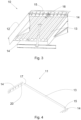
- the ramps (100) of the prior art have a structure (111) to which a transit surface (112) is joined, where said structure (111) is formed by U-shaped longitudinal reinforcements (113) that are welded horizontally to the transit surface (112) and vertically to each of the transverse reinforcements (114) at which they end.
- auxiliary pieces (115) that form the articulation openings of the lip (116) and auxiliary pieces (117) that form the articulation openings of the ramp (100), where said pieces (115, 117) are individually welded to the transverse reinforcements at the outer faces thereof to perform said articulated unions to the lip (116) and to the corresponding loading dock in which they are installed, not shown in the figures.
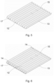
- a ramp (10) provided with a structure (11) to which a transit surface (12) is also joined.
- the structure (11) of the present invention is formed by a plurality of longitudinal reinforcements (13), formed by a flat metal profile, that are coupled to two transverse reinforcements (14) disposed at the longitudinal ends of the ramp (10) that have slotted openings (20). This coupling is performed by inserting the flat profile that forms the longitudinal reinforcement (13) in said slots (20) of the transverse reinforcements (14).
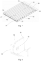
- the coupling takes place such that the terminuses (15, 17) of the longitudinal reinforcements (13) protrude from the outer faces of the transverse reinforcements (14), such that said terminuses (15, 17) at one extreme form the articulation openings (15) of a lip (16) and at the other extreme form the articulation openings (17) of the ramp (10), without requiring the incorporation of auxiliary pieces to form these.
- At least one longitudinal reinforcement finishes in the inner face of at least one transverse reinforcement, without protruding, requiring auxiliary pieces for the articulations.
- the structure (11) is made by engaging the profiles that form the longitudinal reinforcements (13) in the slotted openings (20) disposed in the transverse reinforcements (14)
- the assembly steps for attachment to the transit surface (12) or of the structure between its reinforcements (13, 14) can take place before or after any stage indistinctly, according to the preferences for the manufacturing process.
Landscapes
- Engineering & Computer Science (AREA)
- Mechanical Engineering (AREA)
- Body Structure For Vehicles (AREA)
- Butt Welding And Welding Of Specific Article (AREA)
- Automatic Assembly (AREA)
- Transition And Organic Metals Composition Catalysts For Addition Polymerization (AREA)
- Secondary Cells (AREA)
- Polymerisation Methods In General (AREA)
Applications Claiming Priority (1)
| Application Number | Priority Date | Filing Date | Title |
|---|---|---|---|
| ES201930236A ES2783148B2 (es) | 2019-03-13 | 2019-03-13 | Rampa para muelle de carga y metodo de fabricacion de la misma |
Publications (3)
| Publication Number | Publication Date |
|---|---|
| EP3708525A1 EP3708525A1 (en) | 2020-09-16 |
| EP3708525B1 true EP3708525B1 (en) | 2023-06-07 |
| EP3708525C0 EP3708525C0 (en) | 2023-06-07 |
Family
ID=69903007
Family Applications (1)
| Application Number | Title | Priority Date | Filing Date |
|---|---|---|---|
| EP20162343.6A Active EP3708525B1 (en) | 2019-03-13 | 2020-03-11 | Ramp for a loading dock and manufacturing method for same |
Country Status (3)
| Country | Link |
|---|---|
| EP (1) | EP3708525B1 (pl) |
| ES (2) | ES2783148B2 (pl) |
| PL (1) | PL3708525T3 (pl) |
Family Cites Families (8)
| Publication number | Priority date | Publication date | Assignee | Title |
|---|---|---|---|---|
| US2089891A (en) * | 1934-05-21 | 1937-08-10 | Carnegie Illinois Steel Corp | Grating structure |
| US2666936A (en) * | 1949-04-29 | 1954-01-26 | Thomas O Palmer | Dock plate |
| US2906212A (en) * | 1955-05-19 | 1959-09-29 | American Zinc Lead & Smelting | Runway forming and load receiving multiple car assembly |
| US5781953A (en) * | 1996-07-22 | 1998-07-21 | Overhead Door Corporation | Dock leveler ramp |
| US6524055B1 (en) * | 2001-09-13 | 2003-02-25 | Overbye Transport, Inc. | Semi-trailer loading ramp for transporting ATVs |
| US7430775B2 (en) * | 2002-12-13 | 2008-10-07 | Prairie View Industries, Inc. | Vehicle ramp |
| ES2323101B1 (es) * | 2006-03-09 | 2010-04-06 | Grupo Combursa S.L. | Rampa nivelable antirrobo. |
| ES1075531Y (es) * | 2011-09-20 | 2012-01-26 | Inkema Sist S S L | Rampa o plataforma retractil. |
-
2019
- 2019-03-13 ES ES201930236A patent/ES2783148B2/es active Active
-
2020
- 2020-03-11 EP EP20162343.6A patent/EP3708525B1/en active Active
- 2020-03-11 PL PL20162343.6T patent/PL3708525T3/pl unknown
- 2020-03-11 ES ES20162343T patent/ES2951896T3/es active Active
Also Published As
| Publication number | Publication date |
|---|---|
| ES2951896T3 (es) | 2023-10-25 |
| ES2783148B2 (es) | 2021-01-27 |
| EP3708525C0 (en) | 2023-06-07 |
| EP3708525A1 (en) | 2020-09-16 |
| PL3708525T3 (pl) | 2023-09-25 |
| ES2783148A1 (es) | 2020-09-16 |
Similar Documents
| Publication | Publication Date | Title |
|---|---|---|
| EP2210800B1 (en) | Automobile roof structure | |
| US6668438B2 (en) | Production of vehicles | |
| KR101605116B1 (ko) | 선박 건조시 곡형 블록의 제작 공법 | |
| US20020175039A1 (en) | Escalator support structure | |
| EP3239025A2 (en) | Modular hybrid cross car beam assembly | |
| US20190264777A1 (en) | Rigid chain link and rigid chain equipped with such a link | |
| CN102046418A (zh) | 结构部件、包括靠背的车辆座椅及制造结构部件或靠背的方法 | |
| EP3708525B1 (en) | Ramp for a loading dock and manufacturing method for same | |
| US3901611A (en) | Connector | |
| WO2017120041A1 (en) | Chain link using a pressed-in member | |
| JP2009107549A (ja) | 車体部品の位置決め装置、および、車体部品の位置決め方法 | |
| US6370719B1 (en) | Dock leveler lip construction | |
| US4381842A (en) | Metal enclosure and manufacturing method therefor | |
| US20220003007A1 (en) | Scaffolding system and method for producing said scaffolding system | |
| KR101758588B1 (ko) | 탈형 데크 플레이트 조립방법 및 이에 의해 조립된 탈형 데크 플레이트 | |
| US20230115539A1 (en) | Stirrup module for beam reinforcement system and manufacturing method of beam reinforcement system | |
| JP4974241B2 (ja) | ホイール積載盤 | |
| US10087618B2 (en) | System and method for interlocking structural members | |
| EP1251217A1 (en) | Beam for supports and relative method to obtain said beam | |
| US11078022B1 (en) | Connector block for connecting links in trolley chain | |
| CN108394610B (zh) | 托盘箱底盘 | |
| KR102900286B1 (ko) | 현장 조립형 거푸집의 결속부재 및 그의 시공방법 | |
| KR102828336B1 (ko) | 모듈 철근이 구성된 보 거푸집 및 이의 제작방법 | |
| CN216580702U (zh) | 一种车架梁体及车架总成 | |
| CN109677792B (zh) | 用于冷藏集装箱的地板结构及具有其的冷藏集装箱 |
Legal Events
| Date | Code | Title | Description |
|---|---|---|---|
| PUAI | Public reference made under article 153(3) epc to a published international application that has entered the european phase |
Free format text: ORIGINAL CODE: 0009012 |
|
| STAA | Information on the status of an ep patent application or granted ep patent |
Free format text: STATUS: THE APPLICATION HAS BEEN PUBLISHED |
|
| AK | Designated contracting states |
Kind code of ref document: A1 Designated state(s): AL AT BE BG CH CY CZ DE DK EE ES FI FR GB GR HR HU IE IS IT LI LT LU LV MC MK MT NL NO PL PT RO RS SE SI SK SM TR |
|
| AX | Request for extension of the european patent |
Extension state: BA ME |
|
| RBV | Designated contracting states (corrected) |
Designated state(s): AL AT BE BG CH CY CZ DE DK EE ES FI FR GB GR HR HU IE IS IT LI LT LU LV MC MK MT NL NO PL PT RO RS SE SI SK SM TR |
|
| STAA | Information on the status of an ep patent application or granted ep patent |
Free format text: STATUS: REQUEST FOR EXAMINATION WAS MADE |
|
| 17P | Request for examination filed |
Effective date: 20210317 |
|
| GRAP | Despatch of communication of intention to grant a patent |
Free format text: ORIGINAL CODE: EPIDOSNIGR1 |
|
| STAA | Information on the status of an ep patent application or granted ep patent |
Free format text: STATUS: GRANT OF PATENT IS INTENDED |
|
| INTG | Intention to grant announced |
Effective date: 20220614 |
|
| GRAJ | Information related to disapproval of communication of intention to grant by the applicant or resumption of examination proceedings by the epo deleted |
Free format text: ORIGINAL CODE: EPIDOSDIGR1 |
|
| STAA | Information on the status of an ep patent application or granted ep patent |
Free format text: STATUS: REQUEST FOR EXAMINATION WAS MADE |
|
| INTC | Intention to grant announced (deleted) | ||
| GRAP | Despatch of communication of intention to grant a patent |
Free format text: ORIGINAL CODE: EPIDOSNIGR1 |
|
| STAA | Information on the status of an ep patent application or granted ep patent |
Free format text: STATUS: GRANT OF PATENT IS INTENDED |
|
| INTG | Intention to grant announced |
Effective date: 20230105 |
|
| GRAS | Grant fee paid |
Free format text: ORIGINAL CODE: EPIDOSNIGR3 |
|
| GRAA | (expected) grant |
Free format text: ORIGINAL CODE: 0009210 |
|
| STAA | Information on the status of an ep patent application or granted ep patent |
Free format text: STATUS: THE PATENT HAS BEEN GRANTED |
|
| AK | Designated contracting states |
Kind code of ref document: B1 Designated state(s): AL AT BE BG CH CY CZ DE DK EE ES FI FR GB GR HR HU IE IS IT LI LT LU LV MC MK MT NL NO PL PT RO RS SE SI SK SM TR |
|
| REG | Reference to a national code |
Ref country code: GB Ref legal event code: FG4D |
|
| REG | Reference to a national code |
Ref country code: CH Ref legal event code: EP Ref country code: AT Ref legal event code: REF Ref document number: 1574473 Country of ref document: AT Kind code of ref document: T Effective date: 20230615 |
|
| REG | Reference to a national code |
Ref country code: DE Ref legal event code: R096 Ref document number: 602020011483 Country of ref document: DE |
|
| REG | Reference to a national code |
Ref country code: RO Ref legal event code: EPE |
|
| U01 | Request for unitary effect filed |
Effective date: 20230707 |
|
| U07 | Unitary effect registered |
Designated state(s): AT BE BG DE DK EE FI FR IT LT LU LV MT NL PT SE SI Effective date: 20230713 |
|
| REG | Reference to a national code |
Ref country code: LT Ref legal event code: MG9D |
|
| REG | Reference to a national code |
Ref country code: ES Ref legal event code: FG2A Ref document number: 2951896 Country of ref document: ES Kind code of ref document: T3 Effective date: 20231025 |
|
| PG25 | Lapsed in a contracting state [announced via postgrant information from national office to epo] |
Ref country code: NO Free format text: LAPSE BECAUSE OF FAILURE TO SUBMIT A TRANSLATION OF THE DESCRIPTION OR TO PAY THE FEE WITHIN THE PRESCRIBED TIME-LIMIT Effective date: 20230907 |
|
| PG25 | Lapsed in a contracting state [announced via postgrant information from national office to epo] |
Ref country code: RS Free format text: LAPSE BECAUSE OF FAILURE TO SUBMIT A TRANSLATION OF THE DESCRIPTION OR TO PAY THE FEE WITHIN THE PRESCRIBED TIME-LIMIT Effective date: 20230607 Ref country code: HR Free format text: LAPSE BECAUSE OF FAILURE TO SUBMIT A TRANSLATION OF THE DESCRIPTION OR TO PAY THE FEE WITHIN THE PRESCRIBED TIME-LIMIT Effective date: 20230607 Ref country code: GR Free format text: LAPSE BECAUSE OF FAILURE TO SUBMIT A TRANSLATION OF THE DESCRIPTION OR TO PAY THE FEE WITHIN THE PRESCRIBED TIME-LIMIT Effective date: 20230908 |
|
| PG25 | Lapsed in a contracting state [announced via postgrant information from national office to epo] |
Ref country code: SK Free format text: LAPSE BECAUSE OF FAILURE TO SUBMIT A TRANSLATION OF THE DESCRIPTION OR TO PAY THE FEE WITHIN THE PRESCRIBED TIME-LIMIT Effective date: 20230607 |
|
| PG25 | Lapsed in a contracting state [announced via postgrant information from national office to epo] |
Ref country code: IS Free format text: LAPSE BECAUSE OF FAILURE TO SUBMIT A TRANSLATION OF THE DESCRIPTION OR TO PAY THE FEE WITHIN THE PRESCRIBED TIME-LIMIT Effective date: 20231007 |
|
| PG25 | Lapsed in a contracting state [announced via postgrant information from national office to epo] |
Ref country code: SM Free format text: LAPSE BECAUSE OF FAILURE TO SUBMIT A TRANSLATION OF THE DESCRIPTION OR TO PAY THE FEE WITHIN THE PRESCRIBED TIME-LIMIT Effective date: 20230607 Ref country code: SK Free format text: LAPSE BECAUSE OF FAILURE TO SUBMIT A TRANSLATION OF THE DESCRIPTION OR TO PAY THE FEE WITHIN THE PRESCRIBED TIME-LIMIT Effective date: 20230607 Ref country code: IS Free format text: LAPSE BECAUSE OF FAILURE TO SUBMIT A TRANSLATION OF THE DESCRIPTION OR TO PAY THE FEE WITHIN THE PRESCRIBED TIME-LIMIT Effective date: 20231007 Ref country code: CZ Free format text: LAPSE BECAUSE OF FAILURE TO SUBMIT A TRANSLATION OF THE DESCRIPTION OR TO PAY THE FEE WITHIN THE PRESCRIBED TIME-LIMIT Effective date: 20230607 |
|
| U20 | Renewal fee for the european patent with unitary effect paid |
Year of fee payment: 5 Effective date: 20240126 |
|
| REG | Reference to a national code |
Ref country code: DE Ref legal event code: R097 Ref document number: 602020011483 Country of ref document: DE |
|
| PLBE | No opposition filed within time limit |
Free format text: ORIGINAL CODE: 0009261 |
|
| STAA | Information on the status of an ep patent application or granted ep patent |
Free format text: STATUS: NO OPPOSITION FILED WITHIN TIME LIMIT |
|
| 26N | No opposition filed |
Effective date: 20240308 |
|
| REG | Reference to a national code |
Ref country code: CH Ref legal event code: PL |
|
| PG25 | Lapsed in a contracting state [announced via postgrant information from national office to epo] |
Ref country code: MC Free format text: LAPSE BECAUSE OF FAILURE TO SUBMIT A TRANSLATION OF THE DESCRIPTION OR TO PAY THE FEE WITHIN THE PRESCRIBED TIME-LIMIT Effective date: 20230607 |
|
| PG25 | Lapsed in a contracting state [announced via postgrant information from national office to epo] |
Ref country code: MC Free format text: LAPSE BECAUSE OF FAILURE TO SUBMIT A TRANSLATION OF THE DESCRIPTION OR TO PAY THE FEE WITHIN THE PRESCRIBED TIME-LIMIT Effective date: 20230607 |
|
| PG25 | Lapsed in a contracting state [announced via postgrant information from national office to epo] |
Ref country code: CH Free format text: LAPSE BECAUSE OF NON-PAYMENT OF DUE FEES Effective date: 20240331 |
|
| U20 | Renewal fee for the european patent with unitary effect paid |
Year of fee payment: 6 Effective date: 20250121 |
|
| PGFP | Annual fee paid to national office [announced via postgrant information from national office to epo] |
Ref country code: RO Payment date: 20250211 Year of fee payment: 6 |
|
| PGFP | Annual fee paid to national office [announced via postgrant information from national office to epo] |
Ref country code: IE Payment date: 20250123 Year of fee payment: 6 |
|
| PGFP | Annual fee paid to national office [announced via postgrant information from national office to epo] |
Ref country code: PL Payment date: 20250128 Year of fee payment: 6 |
|
| PGFP | Annual fee paid to national office [announced via postgrant information from national office to epo] |
Ref country code: GB Payment date: 20250116 Year of fee payment: 6 |
|
| PGFP | Annual fee paid to national office [announced via postgrant information from national office to epo] |
Ref country code: ES Payment date: 20250401 Year of fee payment: 6 |
|
| PG25 | Lapsed in a contracting state [announced via postgrant information from national office to epo] |
Ref country code: CY Free format text: LAPSE BECAUSE OF FAILURE TO SUBMIT A TRANSLATION OF THE DESCRIPTION OR TO PAY THE FEE WITHIN THE PRESCRIBED TIME-LIMIT; INVALID AB INITIO Effective date: 20200311 |
|
| PG25 | Lapsed in a contracting state [announced via postgrant information from national office to epo] |
Ref country code: HU Free format text: LAPSE BECAUSE OF FAILURE TO SUBMIT A TRANSLATION OF THE DESCRIPTION OR TO PAY THE FEE WITHIN THE PRESCRIBED TIME-LIMIT; INVALID AB INITIO Effective date: 20200311 |
|
| PG25 | Lapsed in a contracting state [announced via postgrant information from national office to epo] |
Ref country code: TR Free format text: LAPSE BECAUSE OF FAILURE TO SUBMIT A TRANSLATION OF THE DESCRIPTION OR TO PAY THE FEE WITHIN THE PRESCRIBED TIME-LIMIT Effective date: 20230607 |
|
| U20 | Renewal fee for the european patent with unitary effect paid |
Year of fee payment: 7 Effective date: 20260203 |