EP3708522A1 - Transport system for sheets of material - Google Patents
Transport system for sheets of material Download PDFInfo
- Publication number
- EP3708522A1 EP3708522A1 EP20157821.8A EP20157821A EP3708522A1 EP 3708522 A1 EP3708522 A1 EP 3708522A1 EP 20157821 A EP20157821 A EP 20157821A EP 3708522 A1 EP3708522 A1 EP 3708522A1
- Authority
- EP
- European Patent Office
- Prior art keywords
- transport system
- movement path
- movement
- supported
- section
- Prior art date
- Legal status (The legal status is an assumption and is not a legal conclusion. Google has not performed a legal analysis and makes no representation as to the accuracy of the status listed.)
- Granted
Links
- 239000000463 material Substances 0.000 title claims abstract description 69
- 238000000034 method Methods 0.000 claims abstract description 14
- 238000001514 detection method Methods 0.000 claims description 4
- 238000009434 installation Methods 0.000 abstract description 3
- 239000002023 wood Substances 0.000 abstract description 3
- 230000008569 process Effects 0.000 description 6
- 210000000078 claw Anatomy 0.000 description 3
- 230000004913 activation Effects 0.000 description 1
- 230000008901 benefit Effects 0.000 description 1
- 239000011093 chipboard Substances 0.000 description 1
- 238000001816 cooling Methods 0.000 description 1
- 238000001035 drying Methods 0.000 description 1
- 238000005259 measurement Methods 0.000 description 1
- 230000007246 mechanism Effects 0.000 description 1
- 230000003287 optical effect Effects 0.000 description 1
Images


Classifications
-
- B—PERFORMING OPERATIONS; TRANSPORTING
- B65—CONVEYING; PACKING; STORING; HANDLING THIN OR FILAMENTARY MATERIAL
- B65G—TRANSPORT OR STORAGE DEVICES, e.g. CONVEYORS FOR LOADING OR TIPPING, SHOP CONVEYOR SYSTEMS OR PNEUMATIC TUBE CONVEYORS
- B65G47/00—Article or material-handling devices associated with conveyors; Methods employing such devices
- B65G47/34—Devices for discharging articles or materials from conveyor
- B65G47/46—Devices for discharging articles or materials from conveyor and distributing, e.g. automatically, to desired points
- B65G47/51—Devices for discharging articles or materials from conveyor and distributing, e.g. automatically, to desired points according to unprogrammed signals, e.g. influenced by supply situation at destination
- B65G47/5104—Devices for discharging articles or materials from conveyor and distributing, e.g. automatically, to desired points according to unprogrammed signals, e.g. influenced by supply situation at destination for articles
- B65G47/515—First In-Last Out systems [FILO]; Last In-First Out systems [LIFO]
- B65G47/5181—First In-Last Out systems [FILO]; Last In-First Out systems [LIFO] using stacking or destacking arrangements or stacks of articles or article-carriers
-
- B—PERFORMING OPERATIONS; TRANSPORTING
- B65—CONVEYING; PACKING; STORING; HANDLING THIN OR FILAMENTARY MATERIAL
- B65G—TRANSPORT OR STORAGE DEVICES, e.g. CONVEYORS FOR LOADING OR TIPPING, SHOP CONVEYOR SYSTEMS OR PNEUMATIC TUBE CONVEYORS
- B65G47/00—Article or material-handling devices associated with conveyors; Methods employing such devices
- B65G47/52—Devices for transferring articles or materials between conveyors i.e. discharging or feeding devices
- B65G47/64—Switching conveyors
- B65G47/641—Switching conveyors by a linear displacement of the switching conveyor
- B65G47/643—Switching conveyors by a linear displacement of the switching conveyor in a vertical plane
-
- B—PERFORMING OPERATIONS; TRANSPORTING
- B07—SEPARATING SOLIDS FROM SOLIDS; SORTING
- B07C—POSTAL SORTING; SORTING INDIVIDUAL ARTICLES, OR BULK MATERIAL FIT TO BE SORTED PIECE-MEAL, e.g. BY PICKING
- B07C5/00—Sorting according to a characteristic or feature of the articles or material being sorted, e.g. by control effected by devices which detect or measure such characteristic or feature; Sorting by manually actuated devices, e.g. switches
- B07C5/36—Sorting apparatus characterised by the means used for distribution
-
- B—PERFORMING OPERATIONS; TRANSPORTING
- B65—CONVEYING; PACKING; STORING; HANDLING THIN OR FILAMENTARY MATERIAL
- B65G—TRANSPORT OR STORAGE DEVICES, e.g. CONVEYORS FOR LOADING OR TIPPING, SHOP CONVEYOR SYSTEMS OR PNEUMATIC TUBE CONVEYORS
- B65G21/00—Supporting or protective framework or housings for endless load-carriers or traction elements of belt or chain conveyors
- B65G21/20—Means incorporated in, or attached to, framework or housings for guiding load-carriers, traction elements or loads supported on moving surfaces
- B65G21/22—Rails or the like engaging sliding elements or rollers attached to load-carriers or traction elements
-
- B—PERFORMING OPERATIONS; TRANSPORTING
- B65—CONVEYING; PACKING; STORING; HANDLING THIN OR FILAMENTARY MATERIAL
- B65G—TRANSPORT OR STORAGE DEVICES, e.g. CONVEYORS FOR LOADING OR TIPPING, SHOP CONVEYOR SYSTEMS OR PNEUMATIC TUBE CONVEYORS
- B65G37/00—Combinations of mechanical conveyors of the same kind, or of different kinds, of interest apart from their application in particular machines or use in particular manufacturing processes
- B65G37/005—Combinations of mechanical conveyors of the same kind, or of different kinds, of interest apart from their application in particular machines or use in particular manufacturing processes comprising two or more co-operating conveying elements with parallel longitudinal axes
-
- B—PERFORMING OPERATIONS; TRANSPORTING
- B65—CONVEYING; PACKING; STORING; HANDLING THIN OR FILAMENTARY MATERIAL
- B65G—TRANSPORT OR STORAGE DEVICES, e.g. CONVEYORS FOR LOADING OR TIPPING, SHOP CONVEYOR SYSTEMS OR PNEUMATIC TUBE CONVEYORS
- B65G43/00—Control devices, e.g. for safety, warning or fault-correcting
- B65G43/08—Control devices operated by article or material being fed, conveyed or discharged
-
- B—PERFORMING OPERATIONS; TRANSPORTING
- B65—CONVEYING; PACKING; STORING; HANDLING THIN OR FILAMENTARY MATERIAL
- B65G—TRANSPORT OR STORAGE DEVICES, e.g. CONVEYORS FOR LOADING OR TIPPING, SHOP CONVEYOR SYSTEMS OR PNEUMATIC TUBE CONVEYORS
- B65G2201/00—Indexing codes relating to handling devices, e.g. conveyors, characterised by the type of product or load being conveyed or handled
- B65G2201/02—Articles
- B65G2201/0214—Articles of special size, shape or weigh
- B65G2201/022—Flat
-
- B—PERFORMING OPERATIONS; TRANSPORTING
- B65—CONVEYING; PACKING; STORING; HANDLING THIN OR FILAMENTARY MATERIAL
- B65G—TRANSPORT OR STORAGE DEVICES, e.g. CONVEYORS FOR LOADING OR TIPPING, SHOP CONVEYOR SYSTEMS OR PNEUMATIC TUBE CONVEYORS
- B65G2201/00—Indexing codes relating to handling devices, e.g. conveyors, characterised by the type of product or load being conveyed or handled
- B65G2201/02—Articles
- B65G2201/0282—Wooden articles, e.g. logs, trunks or planks
-
- B—PERFORMING OPERATIONS; TRANSPORTING
- B65—CONVEYING; PACKING; STORING; HANDLING THIN OR FILAMENTARY MATERIAL
- B65G—TRANSPORT OR STORAGE DEVICES, e.g. CONVEYORS FOR LOADING OR TIPPING, SHOP CONVEYOR SYSTEMS OR PNEUMATIC TUBE CONVEYORS
- B65G2203/00—Indexing code relating to control or detection of the articles or the load carriers during conveying
- B65G2203/04—Detection means
- B65G2203/042—Sensors
-
- B—PERFORMING OPERATIONS; TRANSPORTING
- B65—CONVEYING; PACKING; STORING; HANDLING THIN OR FILAMENTARY MATERIAL
- B65G—TRANSPORT OR STORAGE DEVICES, e.g. CONVEYORS FOR LOADING OR TIPPING, SHOP CONVEYOR SYSTEMS OR PNEUMATIC TUBE CONVEYORS
- B65G57/00—Stacking of articles
- B65G57/02—Stacking of articles by adding to the top of the stack
- B65G57/11—Stacking of articles by adding to the top of the stack the articles being stacked by direct action of the feeding conveyor
-
- B—PERFORMING OPERATIONS; TRANSPORTING
- B65—CONVEYING; PACKING; STORING; HANDLING THIN OR FILAMENTARY MATERIAL
- B65G—TRANSPORT OR STORAGE DEVICES, e.g. CONVEYORS FOR LOADING OR TIPPING, SHOP CONVEYOR SYSTEMS OR PNEUMATIC TUBE CONVEYORS
- B65G59/00—De-stacking of articles
- B65G59/02—De-stacking from the top of the stack
- B65G59/026—De-stacking from the top of the stack with a stepwise upward movement of the stack
Definitions
- the invention relates to a transport system for material panels, via which a material panel can be transported on a movement path supported by rollers or rotating belts along a direction of movement from a first treatment station to a second treatment station, the transport system at least one feed and / or discharge device within the movement path for Has material plates towards and / or away from the path of movement.
- the invention also relates to a method for supplying and / or diverting material panels in a transport system for material panels, via which a material panel can be transported along a movement path from a first treatment station to a second treatment station on a movement path supported by rollers or rotating belts.
- Material panels are primarily understood to mean wood-based panels that have already been produced in a preferably continuous press and subsequently cut with saws. Chipboard, MDF or OSB, for example, come into question here.
- the treatment stations in the generic term are primarily cutting devices and grinding devices.
- the direction of movement can run from a grinding device to an end cutting device or from a plate cutting device to a grinding device.
- the path of movement for the material plates is usually a flat roller conveyor or a travel path for the material plates supported by carrying belts. Further supports such as gas cushions or sliding surfaces should also be covered by the invention.
- the supply and / or discharge devices were separate arrangements that were used at the beginning or at the end of a transport route, that is to say the movement path from a first to a second treatment station.
- Elaborate switch arrangements were necessary in order to eject material panels that were of lower quality, for example, within a movement path.
- guide rollers or conveyor belts or conveyor belts have been offset in height in order to forward panels on different adjacent paths.
- the object of the invention is to make the installation space of the transport system small in spite of at least one supply or discharge device for wood-based panels.
- the object is achieved in terms of arrangement by the features of the first claim and in particular in that a section of the movement path supported by rollers or circulating belts can be removed in a direction other than the direction of movement and the transport system has a lifting arrangement arranged below the section which is suitable for material panels to feed the path of movement and / or to take from it.
- the basic idea is simply to move a part of the movement path, i.e. a section of the roller or conveyor belts, to the side and thus to move up and transfer plates from below with the lifting arrangement in a space-saving manner, or discarded plates on the lifting arrangement and bring it down out of the path of movement.
- the section must understandably have at least the length of a material plate in the direction of movement. Nevertheless, the effort is significantly lower and more space-saving than with the complicated switch arrangements of the past.
- the lifting arrangement is suitable for feeding material plates to the movement path and receiving them from it.
- the lifting arrangement has a support surface for at least one material plate.
- the stroke is designed so that it extends from a pick-up position or delivery position at the lowest point to approximately the path of movement.
- at least one material plate can conveniently be brought in or taken away, for example with a transport vehicle.
- the lifting device is suitable for receiving a stack of material panels.
- the lifting device only needs to be suitable for performing lifting movements in the size of the material plate thickness.
- the transport system has drive elements which are suitable for moving the material panels from the movement path onto the To move lifting assembly or from the lifting assembly on the path of movement.
- the introduction and discharge process can be automated with these drive elements.
- the transport system preferably has guide elements and centering elements.
- Such guide and centering elements can be used in a wide variety of places in the transport system.
- the material plates must be centered in the direction of movement and aligned straight on the path of movement and they must be deposited on the lifting arrangement with precise edges.
- the transport system has a feed device and a discharge device, one of which can optionally be used.
- This arrangement offers the advantage that, in addition to the normal passage on the path of movement from the first to the second treatment station, one of the two options, namely the introduction or discharge of material panels, can be switched into the stream.
- the feed device and the discharge device can be moved together.
- That the diverting device comprises the remote section of the movement path supported by rollers or revolving belts.
- the second function of a guide device is assigned to the movement path supported by rollers or rotating belts, which was removed for discharge.
- a quality detection sensor for the material plate is preferably arranged in the running direction between the first treatment station and the section of the movement path supported by rollers or circulating belts.
- the quality of the material plate can therefore be detected before it reaches the discharge device. If the material plate is classified as B-goods, for example based on the optical image of its surface or its dimensions, the discharge device can be activated via a central control.
- the object is finally achieved in terms of the method by the features of claim 9 and in particular in that a section of the movement path supported by rollers or revolving belts is removed in a direction other than the direction of movement and a lifting arrangement arranged below the section feeds material plates into the movement path and / or from this absorbs.
- the lifting device picks up a stack of material panels and, in doing so, carries out working stroke steps of material panel thickness.
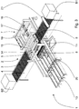
- Fig. 1 shows the transport system 1 according to the invention in its pass-through position in the direction of movement R.
- the material panels 10 are brought from a first treatment station B1, for example a grinding station, to a second treatment station B2, for example a sawing installation, on a movement path 2.
- the treatment stations B1, B2 are shown here only schematically as a box.
- the movement path 2 can be supported, for example, by driven rollers 3 or circumferential support belts 6.
- the first section from the treatment station B1 to a certain section 9 of the movement path 2 is implemented by a roller-supported movement path 3, as is the section from the certain section 9 to the second treatment station B2.
- the section 9 is formed by a belt-supported movement section 5.
- the entire movement path from the first treatment station B1 to the second treatment station B2 is defined here with the reference symbol 2.
- roller-supported movement paths are provided with the reference symbol 3 and belt-supported movement paths with the reference symbol 5.
- section 9 which is essential to the invention, is given an additional reference symbol and can be both belt-supported and roller-supported.
- the movement paths 3 and 5 are parts of the entire movement path 2.
- rollers 4 or belts 6 shown by way of example are driven in order to enable the material panels 10 to be transported easily.
- the transport system 1 also includes a lifting arrangement 11 below the section 9 of the movement path 2. Via a ramp, in this embodiment in the form of a chain-supported supply or discharge 13, material plates can be fed to the lifting arrangement 11 or removed from it, even as a stack of plates .
- a switchover frame 19 which can be moved on rails 20. It has two alternative end positions. In the first it functions as a discharge device 8, in the other as a feed device 7 for material panels. One can also say that one half of the toggle frame 19 (in the Figs. 1 to 3 front) the diversion device 8 and the other half of the changeover frame 19 (in the Figs. 1 to 3 rear) the feed device 7 carries. These two positions that can be taken are explained in more detail in the following figures.
- Fig. 2 shows the transport system 1 with an activated supply device 7.
- the changeover frame was moved (in the drawing to the front).
- the conveyor belts 6 have thereby been laterally removed from the area of the section 9 of the movement path 2.
- Material plates fed to the lifting arrangement 11, possibly also stacks thereof, are raised until the topmost material plate has arrived just above the movement path.
- Claws 16 that can be moved in rails 17 engage one end face of a material panel and pull the top material panel onto the roller-supported movement path 3 between the section 9 and the second treatment station B2.
- the lifting arrangement can be successively moved upwards by the thickness of the material plate and the plates can be brought onto the path of movement one after the other.
- Such a supply of material plates often results when plates in one Storage, for example for the purpose of drying or cooling, were stored before they could be brought to the second treatment station.
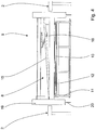
- the changeover frame 19 has been moved back into its starting position.
- the revolving belts 6 are raised via a mechanism (not shown) so that material panels 10, coming from the first treatment station B1, are moved under the belt-supported movement path 5 in the area of section 9.
- the revolving belts 6 take on the task of a belt drive 15 or a guiding and centering device 18 above the material plate 10 to be discharged (not shown). This may be clearer in the detailed view Fig. 4 to recognize.
- the material panel is guided onto the stack of panels that is being formed on the support surface 12 of the lifting arrangement 11 and deposited as the topmost material panel.
- the lifting arrangement moves down by the thickness of the plate for each new plate.
- the diverting process can be automated if a quality recording sensor 21 is arranged between the first treatment station B1 and the section 9 of the movement path 2, the measurement signal of which can be passed on to the diverting device 8. If the quality detection sensor 21 detects that the plate is damaged, for example, the belt-assisted movement path 5 can be run up on the inlet side, so that the reject plate is deflected from the web path 2 onto the lifting arrangement 11.
Landscapes
- Engineering & Computer Science (AREA)
- Mechanical Engineering (AREA)
- Separation, Sorting, Adjustment, Or Bending Of Sheets To Be Conveyed (AREA)
- Structure Of Belt Conveyors (AREA)
Abstract
Die Erfindung betrifft ein Transportsystem für Werkstoffplatten, über welches eine Werkstoffplatte (10) auf einem von Rollen (4) oder umlaufenden Bändern (6) unterstützten Bewegungspfad (2, 3, 5) entlang einer Bewegungsrichtung (R) von einer ersten Behandlungsstation (B1) zu einer zweiten Behandlungsstation (B2) transportierbar ist, wobei das Transportsystem (1) wenigstens eine Zu- und/oder Ableiteinrichtung (7, 8) innerhalb des Bewegungspfades (2, 3, 5) für Werkstoffplatten hin zu und/oder weg von dem Bewegungspfad (2, 3, 5) aufweist. Ferner ist ein Verfahren zum Zu- und/oder Ableiten von Werkstoffplatten in einem Transportsystem betroffen. Um den Bauraum des Transportsystems trotz wenigstens einer Zu- oder Ableiteinrichtung für Holzwerkstoffplatten gering zu gestalten, ist vorgesehen, dass ein Abschnitt (9) des von Rollen (4) oder umlaufenden Bändern (6) unterstützten Bewegungspfades (2, 3, 5) in eine andere als die Bewegungsrichtung (R) entfernbar ist und das Transportsystem eine unterhalb des Abschnitts (9) angeordnete Hubanordnung (11) aufweist, die geeignet ist, Werkstoffplatten (10) dem Bewegungspfad (2, 3, 5) zuzuführen und/oder aus diesem aufzunehmen.The invention relates to a transport system for material panels, via which a material panel (10) on a movement path (2, 3, 5) supported by rollers (4) or rotating belts (6) along a movement direction (R) from a first treatment station (B1) can be transported to a second treatment station (B2), the transport system (1) having at least one supply and / or discharge device (7, 8) within the movement path (2, 3, 5) for material panels towards and / or away from the movement path (2, 3, 5). A method for supplying and / or removing material panels in a transport system is also concerned. In order to keep the installation space of the transport system small despite at least one supply or discharge device for wood-based panels, a section (9) of the movement path (2, 3, 5) supported by rollers (4) or rotating belts (6) is converted into a other than the direction of movement (R) can be removed and the transport system has a lifting arrangement (11) which is arranged below the section (9) and is suitable for feeding material panels (10) to the movement path (2, 3, 5) and / or receiving them from it .
Description
Die Erfindung betrifft ein Transportsystem für Werkstoffplatten, über welches eine Werkstoffplatte auf einem von Rollen oder umlaufenden Bändern unterstützten Bewegungspfad entlang einer Bewegungsrichtung von einer ersten Behandlungsstation zu einer zweiten Behandlungsstation transportierbar ist, wobei das Transportsystem wenigstens eine Zu- und/oder Ableiteinrichtung innerhalb des Bewegungspfades für Werkstoffplatten hin zu und/oder weg von dem Bewegungspfad aufweist.The invention relates to a transport system for material panels, via which a material panel can be transported on a movement path supported by rollers or rotating belts along a direction of movement from a first treatment station to a second treatment station, the transport system at least one feed and / or discharge device within the movement path for Has material plates towards and / or away from the path of movement.
Die Erfindung betrifft außerdem ein Verfahren zum Zu- und/oder Ableiten von Werkstoffplatten in einem Transportsystem für Werkstoffplatten, über welches eine Werkstoffplatte auf einem von Rollen oder umlaufenden Bändern unterstützten Bewegungspfad entlang einer Bewegungsrichtung von einer ersten Behandlungsstation zu einer zweiten Behandlungsstation transportiert werden kann.The invention also relates to a method for supplying and / or diverting material panels in a transport system for material panels, via which a material panel can be transported along a movement path from a first treatment station to a second treatment station on a movement path supported by rollers or rotating belts.
Unter Werkstoffplatten werden in erster Linie Holzwerkstoffplatten verstanden, die bereits in einer vorzugsweise kontinuierlichen Presse hergestellt und im Folgenden mit Sägen geschnitten wurden. Hier kommen beispielsweise Span-, MDF- oder OSB-Platten in Frage.Material panels are primarily understood to mean wood-based panels that have already been produced in a preferably continuous press and subsequently cut with saws. Chipboard, MDF or OSB, for example, come into question here.
Bei den Behandlungsstationen im Oberbegriff handelt es sich in erster Linie um Schneideinrichtungen und Schleifeinrichtungen. Dabei kann die Bewegungsrichtung von einer Schleifeinrichtung zu einer Endschneideeinrichtung oder aber auch von einer Plattenschneideeinrichtung zu einer Schleifeinrichtung verlaufen. Der Bewegungspfad für die Werkstoffplatten ist in der Regel ein ebener Rollengang oder von Tragriemen gestützter Verfahrweg für die Werkstoffplatten. Weitere Unterstützungen wie beispielsweise Gaspolster oder Gleitflächen sollen von der Erfindung mit erfasst sein.The treatment stations in the generic term are primarily cutting devices and grinding devices. The direction of movement can run from a grinding device to an end cutting device or from a plate cutting device to a grinding device. The path of movement for the material plates is usually a flat roller conveyor or a travel path for the material plates supported by carrying belts. Further supports such as gas cushions or sliding surfaces should also be covered by the invention.
Die Zu- und/oder Ableiteinrichtungen waren in der Vergangenheit getrennte Anordnungen, die zu Beginn oder am Ende einer Transportstrecke, also des Bewegungspfades von einer ersten zu einer zweiten Behandlungsstation eingesetzt wurden. Um Innerhalb eines Bewegungspfades Werkstoffplatten, die beispielsweise einer niedrigere Qualität aufwiesen, auszuschleusen, waren aufwändige Weichenanordnungen notwendig. So wurden beispielsweise Führungsrollen oder auch Förderbänder oder -riemen in der Höhe versetzt, um Platten auf unterschiedlichen angrenzenden Pfaden weiterzuleiten.In the past, the supply and / or discharge devices were separate arrangements that were used at the beginning or at the end of a transport route, that is to say the movement path from a first to a second treatment station. Elaborate switch arrangements were necessary in order to eject material panels that were of lower quality, for example, within a movement path. For example, guide rollers or conveyor belts or conveyor belts have been offset in height in order to forward panels on different adjacent paths.
Die Erfindung setzt sich zur Aufgabe, den Bauraum des Transportsystems trotz wenigstens einer Zu- oder Ableiteinrichtung für Holzwerkstoffplatten gering zu gestalten.The object of the invention is to make the installation space of the transport system small in spite of at least one supply or discharge device for wood-based panels.
Die Aufgabe wird anordnungsmäßig durch die Merkmale des ersten Anspruchs und insbesondere dadurch gelöst, dass ein Abschnitt des von Rollen oder umlaufenden Bändern unterstützten Bewegungspfades in eine andere als die Bewegungsrichtung entfernbar ist und das Transportsystem eine unterhalb des Abschnitts angeordnete Hubanordnung aufweist, die geeignet ist, Werkstoffplatten dem Bewegungspfad zuzuführen und/oder aus diesem aufzunehmen.The object is achieved in terms of arrangement by the features of the first claim and in particular in that a section of the movement path supported by rollers or circulating belts can be removed in a direction other than the direction of movement and the transport system has a lifting arrangement arranged below the section which is suitable for material panels to feed the path of movement and / or to take from it.
Die Grundidee besteht einfach darin, einen Teil des Bewegungspfades, also ein Teilstück der Tragrollen- oder -bänder seitlich zu verfahren und somit in raumsparender Weise, Platten von unten mit der Hubanordnung hochzufahren und einzuschleusen oder aber aussortierte Platten auf der Hubanordnung aufzunehmen und nach unten aus dem Bewegungspfad wegzubringen. Dazu muss der Abschnitt verständlicherweise zumindest der Länge einer Werkstoffplatte in Bewegungsrichtung aufweisen. Dennoch ist der Aufwand deutlich geringer und platzsparender als mit den komplizierten Weichenanordnungen der Vergangenheit.The basic idea is simply to move a part of the movement path, i.e. a section of the roller or conveyor belts, to the side and thus to move up and transfer plates from below with the lifting arrangement in a space-saving manner, or discarded plates on the lifting arrangement and bring it down out of the path of movement. For this purpose, the section must understandably have at least the length of a material plate in the direction of movement. Nevertheless, the effort is significantly lower and more space-saving than with the complicated switch arrangements of the past.
Bevorzugt ist demnach vorgesehen, dass die Hubanordnung geeignet ist, Werkstoffplatten dem Bewegungspfad zuzuführen und aus diesem aufzunehmen.Accordingly, it is preferably provided that the lifting arrangement is suitable for feeding material plates to the movement path and receiving them from it.
Die Hubanordnung besitzt dazu eine Auflagefläche für wenigstens eine Werkstoffplatte. Der Hub ist so groß ausgelegt, dass er von einer Aufnahmeposition bzw. Abgabeposition im tiefsten Punkt bis annähernd zum Bewegungspfad reicht. In der Aufnahmeposition bzw. Abgabeposition kann bequem wenigstens eine Werkstoffplatte, beispielsweise mit einem Transportfahrzeug eingebracht oder weggebracht werden.For this purpose, the lifting arrangement has a support surface for at least one material plate. The stroke is designed so that it extends from a pick-up position or delivery position at the lowest point to approximately the path of movement. In the pick-up position or delivery position, at least one material plate can conveniently be brought in or taken away, for example with a transport vehicle.
Es ist vorteilhaft, wenn die Hubvorrichtung geeignet ist, einen Stapel von Werkstoffplatten aufzunehmen.It is advantageous if the lifting device is suitable for receiving a stack of material panels.
In diesem Fall ist es möglich, ohne platzraubende Zuleitungswege gleich mehrere Werkstoffplatten hintereinander von der Hubvorrichtung aufzunehmen und diese dann als Stapel wegbringen zu lassen. Oder umgekehrt können mehrere Werkstoffplatten nacheinander in den Bewegungspfad eingeschleust werden. Dazu muss die Hubvorrichtung nur geeignet sein, Hubbewegungen in der Größe der Werkstoffplattendicke auszuführen.In this case, it is possible, without space-consuming feed lines, to pick up several material panels one after the other from the lifting device and then have them removed as a stack. Or vice versa, several material plates can be fed into the movement path one after the other. For this purpose, the lifting device only needs to be suitable for performing lifting movements in the size of the material plate thickness.
Mit Vorteil ist verbunden, wenn das Transportsystem Antriebselemente aufweist, die geeignet sind, die Werkstoffplatten von dem Bewegungspfad auf die Hubanordnung oder von der Hubanordnung auf den Bewegungspfad zu verschieben.It is advantageous if the transport system has drive elements which are suitable for moving the material panels from the movement path onto the To move lifting assembly or from the lifting assembly on the path of movement.
Mit diesen Antriebselementen kann der Ein- bzw. Ausleitvorgang automatisiert werden.The introduction and discharge process can be automated with these drive elements.
Vorzugsweise weist das Transportsystem Leitelemente und Zentrierelemente auf.The transport system preferably has guide elements and centering elements.
Derartige Leit- und Zentrierelemente können an den verschiedensten Stellen im Transportsystem Anwendung finden. So müssen die Werkstoffplatten in Bewegungsrichtung zentriert und gerade auf dem Bewegungspfad ausgerichtet sein und eine Ablage auf der Hubanordnung kantengenau erfolgt.Such guide and centering elements can be used in a wide variety of places in the transport system. The material plates must be centered in the direction of movement and aligned straight on the path of movement and they must be deposited on the lifting arrangement with precise edges.
Mit Vorteil ist vorgesehen, dass das Transportsystem eine Zuleiteinrichtung und eine Ableiteinrichtung aufweist, von denen wahlweise eine einsetzbar ist.It is advantageously provided that the transport system has a feed device and a discharge device, one of which can optionally be used.
Diese Anordnung bietet den Vorteil, dass man neben dem normalen Durchschleusen auf dem Bewegungspfad von der ersten zur zweiten Behandlungsstation eine der beiden Möglichkeiten, nämlich das Ein- oder das Ausschleusen von Werkstoffplatten in den Strom schalten kann.This arrangement offers the advantage that, in addition to the normal passage on the path of movement from the first to the second treatment station, one of the two options, namely the introduction or discharge of material panels, can be switched into the stream.
Dabei ist bevorzugt, dass die Zuleiteinrichtung und die Ableiteinrichtung gemeinsam verfahrbar sind.It is preferred that the feed device and the discharge device can be moved together.
Es gibt also quasi eine Wechselschaltung zwischen den beiden Optionen des Ein- oder Ausschleusens. Es sind dann nur die jeweils notwendigen Leit-, Führungs- und Antriebselemente oberhalb des von Rollen oder umlaufenden Bändern unterstützten Bewegungspfadabschnitts aktiv, die gerade benötigt werden.So there is a kind of changeover between the two options of inward or outward transfer. There are then only the respectively necessary guide, guide and drive elements above the roller or rotating Bands supported movement path section that are currently required.
Dass die Ableiteinrichtung den entfernten Abschnitt des von Rollen oder umlaufenden Bändern unterstützten Bewegungspfades umfasst.That the diverting device comprises the remote section of the movement path supported by rollers or revolving belts.
Dabei wird dem von Rollen oder umlaufenden Bändern unterstützten Bewegungspfad, der zum Ausschleusen entfernt wurde, die zweite Funktion einer Leiteinrichtung zugeordnet.The second function of a guide device is assigned to the movement path supported by rollers or rotating belts, which was removed for discharge.
Bevorzugt ist in Laufrichtung zwischen der ersten Behandlungsstation und dem Abschnitt des von Rollen oder umlaufenden Bändern unterstützten Bewegungspfades ein Qualitätserfassungssensor für die Werkstoffplatte angeordnet.A quality detection sensor for the material plate is preferably arranged in the running direction between the first treatment station and the section of the movement path supported by rollers or circulating belts.
Es kann also die Qualität der Werkstoffplatte detektiert werden, bevor sie zur Ableiteinrichtung gelangt. Wird die Werkstoffplatte beispielsweise anhand des optischen Bildes Ihrer Oberfläche oder ihrer Abmessungen als B-Ware eingestuft, kann die Ableiteinrichtung über eine zentrale Steuerung aktiviert werden.The quality of the material plate can therefore be detected before it reaches the discharge device. If the material plate is classified as B-goods, for example based on the optical image of its surface or its dimensions, the discharge device can be activated via a central control.
Die Aufgabe wird schließlich verfahrensmäßig durch die Merkmale des Anspruchs 9 und insbesondere dadurch gelöst, dass ein Abschnitt des von Rollen oder umlaufenden Bändern unterstützten Bewegungspfades in eine andere als die Bewegungsrichtung entfernt wird und eine unterhalb des Abschnitts angeordnete Hubanordnung Werkstoffplatten in den Bewegungspfad einschleust und/oder aus diesem aufnimmt.The object is finally achieved in terms of the method by the features of
Die grundlegende Idee ist bereits bei der Beschreibung der Vorrichtungsansprüche erfolgt. Verfahrensmäßig kann auf diese Weise der Transportprozess für die Werkstoffplatten mit der Qualitätssortierung kombiniert werden. Da die Zuführung als Hubanordnung nur den Platz unterhalb des Bewegungspfades benötigt, erfolgt der Prozess in äußerst platzsparender Weise.The basic idea was already given in the description of the device claims. In terms of procedure, the transport process for the material panels can be combined with the quality sorting. Since the feed as a lifting arrangement only requires the space below the movement path, the process takes place in an extremely space-saving manner.
Dabei ist es vorteilhaft, wenn Werkstoffplatten mittels mit dem Transportsystem verbundener Antriebe und Leiteinrichtungen auf den Bewegungspfad gebracht und/oder von dem Bewegungspfad auf die Hubanordnung gelenkt werden.It is advantageous here if material panels are brought onto the movement path by means of drives and guide devices connected to the transport system and / or are directed from the movement path onto the lifting arrangement.
Ebenso ist es zeit- und platzsparend, wenn die Hubvorrichtung einen Stapel aus Werkstoffplatten aufnimmt und dabei Arbeitshubschritte von Werkstoffplattendicke vornimmt.It is also time and space-saving if the lifting device picks up a stack of material panels and, in doing so, carries out working stroke steps of material panel thickness.
Im Folgenden wird die Erfindung anhand eines Ausführungsbeispiels darstellender Zeichnungen näher erläutert. Es zeigen
- Fig. 1
- ein erfindungsgemäßes System zum Transport von Werkstoffplatten mit einer Ein- und Ausleiteinrichtung in Durchlaufposition,
- Fig. 2
- ein erfindungsgemäßes System zum Transport von Werkstoffplatten mit einer Ein- und Ausleiteinrichtung in Zuführposition.
- Fig. 3
- ein erfindungsgemäßes System zum Transport von Werkstoffplatten mit einer Ein- und Ausleiteinrichtung in Ausleitposition
- Fig. 4
- Ein schematische Detailzeichnung des Ausleitmittels.
- Fig. 1
- a system according to the invention for the transport of material panels with an inlet and outlet device in the throughput position,
- Fig. 2
- a system according to the invention for the transport of material panels with an inlet and outlet device in the feed position.
- Fig. 3
- a system according to the invention for the transport of material panels with an inlet and outlet device in the outlet position
- Fig. 4
- A schematic detailed drawing of the discharge means.
Der Bewegungspfad 2 kann beispielsweise durch angetriebene Rollen 3 oder umlaufende Tragbänder 6 unterstützt sein. In diesem Ausführungsbeispiel ist auch aus Gründen der späteren Übersichtlichkeit das erste Teilstück von der Behandlungsstation B1 bis zu einem bestimmten Abschnitt 9 des Bewegungspfades 2 durch einen rollenunterstützten Bewegungspfad 3 realisiert, genauso wie das Teilstück von dem bestimmten Abschnitt 9 bis zur zweiten Behandlungsstation B2. Der Abschnitt 9 ist im Ausführungsbeispiel durch einen bandunterstützten Bewegungsabschnitt 5 gebildet.The
Hinsichtlich des Bewegungspfades wird hier der gesamte Bewegungspfad von der ersten Behandlungsstation B1 zur zweiten Behandlungsstation B2 mit dem Bezugszeichen 2 definiert. Beispielhaft sind rollenunterstützte Bewegungspfade mit dem Bezugszeichen 3 versehen und bandunterstützte Bewegungspfade mit dem Bezugszeichen 5. Der erfindungswesentliche Abschnitt 9 bekommt wegen seiner Bedeutung ein zusätzliches Bezugszeichen und kann sowohl bandunterstützt als auch rollenunterstützt sein. Die bewegungspfade 3 und 5 sind Teilstücke des Gesamten Bewegungspfades 2.With regard to the movement path, the entire movement path from the first treatment station B1 to the second treatment station B2 is defined here with the
Es sind selbstverständlich auch andere Bewegungspfade im Rahmen der Erfindung möglich. Die beispielhaft dargestellten Rollen 4 bzw. Bänder 6 sind angetrieben, um einen einfachen Transport der Werkstoffplatten 10 zu ermöglichen.Other movement paths are of course also possible within the scope of the invention. The
Das Transportsystem 1 umfasst ferner eine Hubanordnung 11 unterhalb des Abschnitts 9 des Bewegungspfades 2. Über eine Rampe, in diesem Ausführungsbeispiel in Form einer kettenunterstützten Zu- bzw. Abfuhr 13 können Werkstoffplatten Auflagefläche 12 der Hubanordnung 11 zugeführt oder von ihr entnommen werden, sogar als Plattenstapel.The
Weiterhin ist ein Umschaltrahmen 19 vorgesehen, der auf Schienen 20 verfahren werden kann. Er hat zwei alternative Endpositionen. In der ersten fungiert er als Ableiteinrichtung 8, in der anderen als Zuleiteinrichtung 7 für Werkstoffplatten. Man kann auch sagen, dass die eine Hälfte des Umschaltrahmens 19 (in der
Den gegenteiligen Prozess und damit die Aktivierung der Ableiteinrichtung 8 zeigt
Ein solcher Ausschleusungsvorgang ist dann sinnvoll, wenn die Platte nicht den gewünschten Qualitätsanforderungen entspricht. Der Ausleitvorgang kann dabei automatisiert werden, wenn zwischen der ersten Behandlungsstation B1 und dem Abschnitt 9 des Bewegungspfades 2 ein Qualitätserfassungssensor 21 angeordnet ist, dessen Messsignal an Ableiteinrichtung 8 weitergegeben werden kann. Wenn der Qualitätserfassungssensor 21 erkennt, dass die Platte beispielsweise beschädigt ist, kann der bandunterstützte Bewegungspfad 5 einlaufseitig hochgefahren werden, so dass die Ausschussplatte von dem Bahnlaufpfad 2 auf die Hubanordnung 11 umgelenkt wird.Such a discharge process makes sense if the plate does not meet the desired quality requirements. The diverting process can be automated if a
Sowohl für die Zuleiteinrichtung 7 als auch für Ableiteinrichtung 8 muss der rollen- oder bandunterstützte Abschnitt 9 des Bahnlaufpfades in eine andere als die Bewegungsrichtung entfernt werden, um den entsprechenden Vorgang möglich zu machen.
Claims (12)
Priority Applications (1)
| Application Number | Priority Date | Filing Date | Title |
|---|---|---|---|
| PL20157821T PL3708522T3 (en) | 2019-03-13 | 2020-02-18 | Transport system for sheets of material |
Applications Claiming Priority (1)
| Application Number | Priority Date | Filing Date | Title |
|---|---|---|---|
| DE102019001784.6A DE102019001784A1 (en) | 2019-03-13 | 2019-03-13 | Transport system for material panels |
Publications (2)
| Publication Number | Publication Date |
|---|---|
| EP3708522A1 true EP3708522A1 (en) | 2020-09-16 |
| EP3708522B1 EP3708522B1 (en) | 2021-09-08 |
Family
ID=69784009
Family Applications (1)
| Application Number | Title | Priority Date | Filing Date |
|---|---|---|---|
| EP20157821.8A Active EP3708522B1 (en) | 2019-03-13 | 2020-02-18 | Transport system for sheets of material |
Country Status (4)
| Country | Link |
|---|---|
| US (1) | US11066251B2 (en) |
| EP (1) | EP3708522B1 (en) |
| DE (1) | DE102019001784A1 (en) |
| PL (1) | PL3708522T3 (en) |
Cited By (1)
| Publication number | Priority date | Publication date | Assignee | Title |
|---|---|---|---|---|
| CN112722851A (en) * | 2020-12-26 | 2021-04-30 | 海控三鑫(蚌埠)新能源材料有限公司 | Automatic sheet discharging device for waste sheets before glass tempering |
Families Citing this family (5)
| Publication number | Priority date | Publication date | Assignee | Title |
|---|---|---|---|---|
| CN112317360A (en) * | 2020-11-25 | 2021-02-05 | 惠州市伊索家具有限公司 | Efficient full-automatic processing production line for plates for furniture |
| CN112607375B (en) * | 2020-12-11 | 2022-10-11 | 豪德机械(上海)有限公司 | Stacking equipment for multi-size floors |
| CN112756275B (en) * | 2020-12-30 | 2023-04-11 | 运易通科技有限公司 | Air logistics transportation ground service classifier and using method |
| CN114632720B (en) * | 2022-05-20 | 2022-09-30 | 百信信息技术有限公司 | Automatic material system that divides of production line |
| CN115417121A (en) * | 2022-10-24 | 2022-12-02 | 成都市和乐门业有限公司 | Vertical reversing feeding and discharging conveying device suitable for processing door frame metal plate |
Citations (3)
| Publication number | Priority date | Publication date | Assignee | Title |
|---|---|---|---|---|
| US2981399A (en) * | 1958-02-26 | 1961-04-25 | Coe Mfg Co | Apparatus for handling rigid sheet material |
| US5421446A (en) * | 1993-03-12 | 1995-06-06 | United Parcel Service Of America, Inc. | Article diverter apparatus for use in conveyor systems |
| DE19963021A1 (en) * | 1999-10-11 | 2001-06-21 | P & P Materialflussysteme Gmbh | Transporter to receive and take away stacked one-piece items, with third conveyor to stack sorted goods in magazine |
Family Cites Families (15)
| Publication number | Priority date | Publication date | Assignee | Title |
|---|---|---|---|---|
| BE678711A (en) | 1965-04-07 | 1966-09-01 | ||
| DE1917062C3 (en) | 1969-04-02 | 1978-10-19 | Maschinenfabrik Loesch Gmbh, 8550 Forchheim | Device for the automatic distribution of objects |
| DE1925780A1 (en) | 1969-05-21 | 1970-12-23 | J Grenzebach Maschb Fa | Device for conveying and stacking plates or the like. |
| US3712608A (en) | 1971-05-21 | 1973-01-23 | Jeddeloh Bros Sweed Mills Inc | Apparatus for stacking sheets |
| DE2815459A1 (en) | 1978-04-10 | 1979-10-11 | Demag Ag | Container and pallet storage equipment - has detachable holder above conveyor track section which can be lifted |
| US4499987A (en) | 1982-08-30 | 1985-02-19 | Long Charles P | Accumulator for a carton filling and packing production line |
| DD256495A1 (en) | 1986-12-30 | 1988-05-11 | Verkehrs Und Tiefbaukomb Frank | METHOD OF MAGAZINING, DEMAGAZINATING AND STORING ELEMENTS TRANSPORTED ON TRACKS, PREFERABLY LAYEROUS ELEMENTS |
| DE3915139A1 (en) | 1989-05-09 | 1990-11-15 | Focke & Co | METHOD AND SYSTEM FOR REORDERING SORTED PALLETED ITEMS TO GROUPS OF CERTAIN SORT ASSEMBLY |
| IT1258194B (en) | 1992-08-26 | 1996-02-21 | Mopa Srl | STATION OF DISTRIBUTION OF PRODUCTS ON A SUPPLY LINE OF PACKAGING MACHINES OR POSSIBLE STORAGE |
| JP2005350147A (en) * | 2004-06-08 | 2005-12-22 | Star Techno Kk | Free-flow transport system |
| DE102006015020A1 (en) | 2006-03-31 | 2007-10-04 | Dieffenbacher Gmbh + Co. Kg | Hot plates pre-stacking method for use during manufacturing of material plates, involves declining pre-stack to lower layer after forming stack in upper layer and accelerating in lower layer when formation of new stack begins in upper layer |
| ATE515466T1 (en) * | 2006-09-15 | 2011-07-15 | Ligmatech Automationssysteme | DEVICE AND METHOD FOR PLACING STACKS OF WORKPIECES ON A CONVEYOR |
| DE102013216823A1 (en) | 2013-08-23 | 2015-02-26 | Siemens Aktiengesellschaft | Storage device for stackable containers |
| DE202016008555U1 (en) | 2016-05-06 | 2018-06-04 | Bleichert Automation Gmbh & Co. Kg | Transfer device for the transfer of general cargo |
| DE202018004698U1 (en) | 2018-10-10 | 2018-11-23 | Siempelkamp Maschinen- Und Anlagenbau Gmbh | Device for transporting material plates |
-
2019
- 2019-03-13 DE DE102019001784.6A patent/DE102019001784A1/en active Pending
-
2020
- 2020-02-18 EP EP20157821.8A patent/EP3708522B1/en active Active
- 2020-02-18 PL PL20157821T patent/PL3708522T3/en unknown
- 2020-03-13 US US16/817,663 patent/US11066251B2/en active Active
Patent Citations (3)
| Publication number | Priority date | Publication date | Assignee | Title |
|---|---|---|---|---|
| US2981399A (en) * | 1958-02-26 | 1961-04-25 | Coe Mfg Co | Apparatus for handling rigid sheet material |
| US5421446A (en) * | 1993-03-12 | 1995-06-06 | United Parcel Service Of America, Inc. | Article diverter apparatus for use in conveyor systems |
| DE19963021A1 (en) * | 1999-10-11 | 2001-06-21 | P & P Materialflussysteme Gmbh | Transporter to receive and take away stacked one-piece items, with third conveyor to stack sorted goods in magazine |
Cited By (1)
| Publication number | Priority date | Publication date | Assignee | Title |
|---|---|---|---|---|
| CN112722851A (en) * | 2020-12-26 | 2021-04-30 | 海控三鑫(蚌埠)新能源材料有限公司 | Automatic sheet discharging device for waste sheets before glass tempering |
Also Published As
| Publication number | Publication date |
|---|---|
| PL3708522T3 (en) | 2022-01-31 |
| US11066251B2 (en) | 2021-07-20 |
| DE102019001784A1 (en) | 2020-09-17 |
| EP3708522B1 (en) | 2021-09-08 |
| US20200290821A1 (en) | 2020-09-17 |
Similar Documents
| Publication | Publication Date | Title |
|---|---|---|
| EP3708522B1 (en) | Transport system for sheets of material | |
| EP0860253A2 (en) | Method and apparatus for the manufacture of a multi-layered door | |
| AT501784B1 (en) | PANEL | |
| EP1889699B1 (en) | Device for separating waste parts of workpieces, with a saw, in particular an optimising chopsaw and method using such a device | |
| EP1611039B1 (en) | Transport device, in particular for panel-type workpieces | |
| WO2002090044A1 (en) | Device for returning workpieces | |
| EP0870582A1 (en) | Method and apparatus for removing bad products from a sheet cutting machine | |
| DE102008061351B4 (en) | Plate transport device and method for its control | |
| DE4113479A1 (en) | Device for stacking continually arriving plates - has rapid automatic changeover system for pallet trucks | |
| DE10047385C2 (en) | Method and device for machining continuously moving workpieces | |
| EP3369663B1 (en) | Collar forming device for elongated workpieces and method for bundling elongated workpieces | |
| EP0822739B1 (en) | Automated apparatus for printed circuit board inspection | |
| DE102007035437B3 (en) | Pivoting transport device for flat pieces of material | |
| DE102004048275B3 (en) | Guide device to feed press mats to press for making chipboard has mat dropping device in form of turning table in transporting plane of both conveyors | |
| EP2179950B1 (en) | Storage device for printing plates | |
| EP0810174B1 (en) | Device for vertically stacking printed products | |
| DE202007015954U1 (en) | Wood processing plant | |
| DE102006025170B3 (en) | Method for transporting substrates in placement machines and transport systems | |
| DE3044060C2 (en) | Device for removing flesh from hides | |
| DE2952012C2 (en) | Pressure device for edge banding | |
| DE102011103289B4 (en) | Method and apparatus for assembling components of sandwich framed doors and sandwich frame furniture panels | |
| DE19948704C1 (en) | Unit for combined transporting and turning a horizontal stack of paper sheets, comprises a displaceable and rotatable disk and a fixed holding-down plate whose surface has a lower coefficient of friction | |
| DE3246882A1 (en) | WOODWORKING MACHINE FOR BOTH WORKING OF LONG-TERM WOOD WORKPIECES | |
| DE4213201A1 (en) | Conveyor system for moving stacks of paper sheets - has reject sluice for faulty stacks set between two conveyors to avoid unnecessary handling and wastage of wrapping materials. | |
| AT410541B (en) | DEVICE FOR STACKING FORMAT CUTS WITH A TRAVELABLE FORK CAR |
Legal Events
| Date | Code | Title | Description |
|---|---|---|---|
| PUAI | Public reference made under article 153(3) epc to a published international application that has entered the european phase |
Free format text: ORIGINAL CODE: 0009012 |
|
| STAA | Information on the status of an ep patent application or granted ep patent |
Free format text: STATUS: THE APPLICATION HAS BEEN PUBLISHED |
|
| AK | Designated contracting states |
Kind code of ref document: A1 Designated state(s): AL AT BE BG CH CY CZ DE DK EE ES FI FR GB GR HR HU IE IS IT LI LT LU LV MC MK MT NL NO PL PT RO RS SE SI SK SM TR |
|
| AX | Request for extension of the european patent |
Extension state: BA ME |
|
| STAA | Information on the status of an ep patent application or granted ep patent |
Free format text: STATUS: REQUEST FOR EXAMINATION WAS MADE |
|
| 17P | Request for examination filed |
Effective date: 20201009 |
|
| RBV | Designated contracting states (corrected) |
Designated state(s): AL AT BE BG CH CY CZ DE DK EE ES FI FR GB GR HR HU IE IS IT LI LT LU LV MC MK MT NL NO PL PT RO RS SE SI SK SM TR |
|
| RIC1 | Information provided on ipc code assigned before grant |
Ipc: B65G 47/51 20060101AFI20210219BHEP |
|
| GRAP | Despatch of communication of intention to grant a patent |
Free format text: ORIGINAL CODE: EPIDOSNIGR1 |
|
| STAA | Information on the status of an ep patent application or granted ep patent |
Free format text: STATUS: GRANT OF PATENT IS INTENDED |
|
| INTG | Intention to grant announced |
Effective date: 20210420 |
|
| GRAS | Grant fee paid |
Free format text: ORIGINAL CODE: EPIDOSNIGR3 |
|
| GRAA | (expected) grant |
Free format text: ORIGINAL CODE: 0009210 |
|
| STAA | Information on the status of an ep patent application or granted ep patent |
Free format text: STATUS: THE PATENT HAS BEEN GRANTED |
|
| AK | Designated contracting states |
Kind code of ref document: B1 Designated state(s): AL AT BE BG CH CY CZ DE DK EE ES FI FR GB GR HR HU IE IS IT LI LT LU LV MC MK MT NL NO PL PT RO RS SE SI SK SM TR |
|
| REG | Reference to a national code |
Ref country code: GB Ref legal event code: FG4D Free format text: NOT ENGLISH |
|
| REG | Reference to a national code |
Ref country code: CH Ref legal event code: EP Ref country code: AT Ref legal event code: REF Ref document number: 1428418 Country of ref document: AT Kind code of ref document: T Effective date: 20210915 |
|
| REG | Reference to a national code |
Ref country code: DE Ref legal event code: R096 Ref document number: 502020000169 Country of ref document: DE |
|
| REG | Reference to a national code |
Ref country code: IE Ref legal event code: FG4D Free format text: LANGUAGE OF EP DOCUMENT: GERMAN |
|
| REG | Reference to a national code |
Ref country code: FI Ref legal event code: FGE |
|
| REG | Reference to a national code |
Ref country code: SE Ref legal event code: TRGR |
|
| REG | Reference to a national code |
Ref country code: LT Ref legal event code: MG9D |
|
| REG | Reference to a national code |
Ref country code: NL Ref legal event code: MP Effective date: 20210908 |
|
| PG25 | Lapsed in a contracting state [announced via postgrant information from national office to epo] |
Ref country code: ES Free format text: LAPSE BECAUSE OF FAILURE TO SUBMIT A TRANSLATION OF THE DESCRIPTION OR TO PAY THE FEE WITHIN THE PRESCRIBED TIME-LIMIT Effective date: 20210908 Ref country code: RS Free format text: LAPSE BECAUSE OF FAILURE TO SUBMIT A TRANSLATION OF THE DESCRIPTION OR TO PAY THE FEE WITHIN THE PRESCRIBED TIME-LIMIT Effective date: 20210908 Ref country code: NO Free format text: LAPSE BECAUSE OF FAILURE TO SUBMIT A TRANSLATION OF THE DESCRIPTION OR TO PAY THE FEE WITHIN THE PRESCRIBED TIME-LIMIT Effective date: 20211208 Ref country code: HR Free format text: LAPSE BECAUSE OF FAILURE TO SUBMIT A TRANSLATION OF THE DESCRIPTION OR TO PAY THE FEE WITHIN THE PRESCRIBED TIME-LIMIT Effective date: 20210908 Ref country code: LT Free format text: LAPSE BECAUSE OF FAILURE TO SUBMIT A TRANSLATION OF THE DESCRIPTION OR TO PAY THE FEE WITHIN THE PRESCRIBED TIME-LIMIT Effective date: 20210908 |
|
| PG25 | Lapsed in a contracting state [announced via postgrant information from national office to epo] |
Ref country code: LV Free format text: LAPSE BECAUSE OF FAILURE TO SUBMIT A TRANSLATION OF THE DESCRIPTION OR TO PAY THE FEE WITHIN THE PRESCRIBED TIME-LIMIT Effective date: 20210908 Ref country code: GR Free format text: LAPSE BECAUSE OF FAILURE TO SUBMIT A TRANSLATION OF THE DESCRIPTION OR TO PAY THE FEE WITHIN THE PRESCRIBED TIME-LIMIT Effective date: 20211209 |
|
| PG25 | Lapsed in a contracting state [announced via postgrant information from national office to epo] |
Ref country code: IS Free format text: LAPSE BECAUSE OF FAILURE TO SUBMIT A TRANSLATION OF THE DESCRIPTION OR TO PAY THE FEE WITHIN THE PRESCRIBED TIME-LIMIT Effective date: 20220108 Ref country code: SM Free format text: LAPSE BECAUSE OF FAILURE TO SUBMIT A TRANSLATION OF THE DESCRIPTION OR TO PAY THE FEE WITHIN THE PRESCRIBED TIME-LIMIT Effective date: 20210908 Ref country code: SK Free format text: LAPSE BECAUSE OF FAILURE TO SUBMIT A TRANSLATION OF THE DESCRIPTION OR TO PAY THE FEE WITHIN THE PRESCRIBED TIME-LIMIT Effective date: 20210908 Ref country code: RO Free format text: LAPSE BECAUSE OF FAILURE TO SUBMIT A TRANSLATION OF THE DESCRIPTION OR TO PAY THE FEE WITHIN THE PRESCRIBED TIME-LIMIT Effective date: 20210908 Ref country code: PT Free format text: LAPSE BECAUSE OF FAILURE TO SUBMIT A TRANSLATION OF THE DESCRIPTION OR TO PAY THE FEE WITHIN THE PRESCRIBED TIME-LIMIT Effective date: 20220110 Ref country code: NL Free format text: LAPSE BECAUSE OF FAILURE TO SUBMIT A TRANSLATION OF THE DESCRIPTION OR TO PAY THE FEE WITHIN THE PRESCRIBED TIME-LIMIT Effective date: 20210908 Ref country code: EE Free format text: LAPSE BECAUSE OF FAILURE TO SUBMIT A TRANSLATION OF THE DESCRIPTION OR TO PAY THE FEE WITHIN THE PRESCRIBED TIME-LIMIT Effective date: 20210908 Ref country code: CZ Free format text: LAPSE BECAUSE OF FAILURE TO SUBMIT A TRANSLATION OF THE DESCRIPTION OR TO PAY THE FEE WITHIN THE PRESCRIBED TIME-LIMIT Effective date: 20210908 Ref country code: AL Free format text: LAPSE BECAUSE OF FAILURE TO SUBMIT A TRANSLATION OF THE DESCRIPTION OR TO PAY THE FEE WITHIN THE PRESCRIBED TIME-LIMIT Effective date: 20210908 |
|
| REG | Reference to a national code |
Ref country code: DE Ref legal event code: R026 Ref document number: 502020000169 Country of ref document: DE |
|
| PLBI | Opposition filed |
Free format text: ORIGINAL CODE: 0009260 |
|
| PLAB | Opposition data, opponent's data or that of the opponent's representative modified |
Free format text: ORIGINAL CODE: 0009299OPPO |
|
| PLAX | Notice of opposition and request to file observation + time limit sent |
Free format text: ORIGINAL CODE: EPIDOSNOBS2 |
|
| REG | Reference to a national code |
Ref country code: FI Ref legal event code: MDE Opponent name: DIEFFENBACHER GMBH MASCHINEN- UND ANLAGENBAU |
|
| 26 | Opposition filed |
Opponent name: DIEFFENBACHER GMBH MASCHINEN- UND ANLAGENBAU Effective date: 20220608 |
|
| R26 | Opposition filed (corrected) |
Opponent name: DIEFFENBACHER GMBH MASCHINEN- UND ANLAGENBAU Effective date: 20220608 |
|
| PG25 | Lapsed in a contracting state [announced via postgrant information from national office to epo] |
Ref country code: DK Free format text: LAPSE BECAUSE OF FAILURE TO SUBMIT A TRANSLATION OF THE DESCRIPTION OR TO PAY THE FEE WITHIN THE PRESCRIBED TIME-LIMIT Effective date: 20210908 |
|
| PG25 | Lapsed in a contracting state [announced via postgrant information from national office to epo] |
Ref country code: SI Free format text: LAPSE BECAUSE OF FAILURE TO SUBMIT A TRANSLATION OF THE DESCRIPTION OR TO PAY THE FEE WITHIN THE PRESCRIBED TIME-LIMIT Effective date: 20210908 |
|
| PG25 | Lapsed in a contracting state [announced via postgrant information from national office to epo] |
Ref country code: MC Free format text: LAPSE BECAUSE OF FAILURE TO SUBMIT A TRANSLATION OF THE DESCRIPTION OR TO PAY THE FEE WITHIN THE PRESCRIBED TIME-LIMIT Effective date: 20210908 |
|
| PLBB | Reply of patent proprietor to notice(s) of opposition received |
Free format text: ORIGINAL CODE: EPIDOSNOBS3 |
|
| REG | Reference to a national code |
Ref country code: BE Ref legal event code: MM Effective date: 20220228 |
|
| PG25 | Lapsed in a contracting state [announced via postgrant information from national office to epo] |
Ref country code: LU Free format text: LAPSE BECAUSE OF NON-PAYMENT OF DUE FEES Effective date: 20220218 |
|
| PG25 | Lapsed in a contracting state [announced via postgrant information from national office to epo] |
Ref country code: IE Free format text: LAPSE BECAUSE OF NON-PAYMENT OF DUE FEES Effective date: 20220218 |
|
| PG25 | Lapsed in a contracting state [announced via postgrant information from national office to epo] |
Ref country code: BE Free format text: LAPSE BECAUSE OF NON-PAYMENT OF DUE FEES Effective date: 20220228 |
|
| PGFP | Annual fee paid to national office [announced via postgrant information from national office to epo] |
Ref country code: FR Payment date: 20230222 Year of fee payment: 4 |
|
| PGFP | Annual fee paid to national office [announced via postgrant information from national office to epo] |
Ref country code: TR Payment date: 20230213 Year of fee payment: 4 Ref country code: SE Payment date: 20230220 Year of fee payment: 4 Ref country code: PL Payment date: 20230125 Year of fee payment: 4 Ref country code: IT Payment date: 20230228 Year of fee payment: 4 |
|
| REG | Reference to a national code |
Ref country code: CH Ref legal event code: PL |
|
| PG25 | Lapsed in a contracting state [announced via postgrant information from national office to epo] |
Ref country code: LI Free format text: LAPSE BECAUSE OF NON-PAYMENT OF DUE FEES Effective date: 20230228 Ref country code: CH Free format text: LAPSE BECAUSE OF NON-PAYMENT OF DUE FEES Effective date: 20230228 |
|
| APAH | Appeal reference modified |
Free format text: ORIGINAL CODE: EPIDOSCREFNO |
|
| APBM | Appeal reference recorded |
Free format text: ORIGINAL CODE: EPIDOSNREFNO |
|
| APBP | Date of receipt of notice of appeal recorded |
Free format text: ORIGINAL CODE: EPIDOSNNOA2O |
|
| PG25 | Lapsed in a contracting state [announced via postgrant information from national office to epo] |
Ref country code: MK Free format text: LAPSE BECAUSE OF FAILURE TO SUBMIT A TRANSLATION OF THE DESCRIPTION OR TO PAY THE FEE WITHIN THE PRESCRIBED TIME-LIMIT Effective date: 20210908 Ref country code: CY Free format text: LAPSE BECAUSE OF FAILURE TO SUBMIT A TRANSLATION OF THE DESCRIPTION OR TO PAY THE FEE WITHIN THE PRESCRIBED TIME-LIMIT Effective date: 20210908 |
|
| PGFP | Annual fee paid to national office [announced via postgrant information from national office to epo] |
Ref country code: FI Payment date: 20240220 Year of fee payment: 5 Ref country code: DE Payment date: 20240228 Year of fee payment: 5 Ref country code: BG Payment date: 20240228 Year of fee payment: 5 |
|
| APBU | Appeal procedure closed |
Free format text: ORIGINAL CODE: EPIDOSNNOA9O |