EP3708488B1 - Rotating device and aircraft - Google Patents
Rotating device and aircraft Download PDFInfo
- Publication number
- EP3708488B1 EP3708488B1 EP20156115.6A EP20156115A EP3708488B1 EP 3708488 B1 EP3708488 B1 EP 3708488B1 EP 20156115 A EP20156115 A EP 20156115A EP 3708488 B1 EP3708488 B1 EP 3708488B1
- Authority
- EP
- European Patent Office
- Prior art keywords
- rotating
- ring
- rotating ring
- gear
- motor
- Prior art date
- Legal status (The legal status is an assumption and is not a legal conclusion. Google has not performed a legal analysis and makes no representation as to the accuracy of the status listed.)
- Active
Links
- 230000007246 mechanism Effects 0.000 claims description 75
- 230000005540 biological transmission Effects 0.000 claims description 48
- 239000012530 fluid Substances 0.000 claims description 14
- 230000008878 coupling Effects 0.000 description 7
- 238000010168 coupling process Methods 0.000 description 7
- 238000005859 coupling reaction Methods 0.000 description 7
- 230000006866 deterioration Effects 0.000 description 3
- 230000006872 improvement Effects 0.000 description 3
- 239000000725 suspension Substances 0.000 description 3
- 239000002184 metal Substances 0.000 description 2
- 238000000034 method Methods 0.000 description 2
- 238000009423 ventilation Methods 0.000 description 2
- XLYOFNOQVPJJNP-UHFFFAOYSA-N water Substances O XLYOFNOQVPJJNP-UHFFFAOYSA-N 0.000 description 2
- 229920002430 Fibre-reinforced plastic Polymers 0.000 description 1
- 238000001816 cooling Methods 0.000 description 1
- 230000000694 effects Effects 0.000 description 1
- 239000011151 fibre-reinforced plastic Substances 0.000 description 1
- 230000005484 gravity Effects 0.000 description 1
- 230000004048 modification Effects 0.000 description 1
- 238000012986 modification Methods 0.000 description 1
- 239000004033 plastic Substances 0.000 description 1
- 229920003023 plastic Polymers 0.000 description 1
- 238000005096 rolling process Methods 0.000 description 1
Images


Classifications
-
- B—PERFORMING OPERATIONS; TRANSPORTING
- B64—AIRCRAFT; AVIATION; COSMONAUTICS
- B64C—AEROPLANES; HELICOPTERS
- B64C11/00—Propellers, e.g. of ducted type; Features common to propellers and rotors for rotorcraft
- B64C11/001—Shrouded propellers
-
- B—PERFORMING OPERATIONS; TRANSPORTING
- B60—VEHICLES IN GENERAL
- B60B—VEHICLE WHEELS; CASTORS; AXLES FOR WHEELS OR CASTORS; INCREASING WHEEL ADHESION
- B60B19/00—Wheels not otherwise provided for or having characteristics specified in one of the subgroups of this group
-
- B—PERFORMING OPERATIONS; TRANSPORTING
- B64—AIRCRAFT; AVIATION; COSMONAUTICS
- B64C—AEROPLANES; HELICOPTERS
- B64C11/00—Propellers, e.g. of ducted type; Features common to propellers and rotors for rotorcraft
- B64C11/46—Arrangements of, or constructional features peculiar to, multiple propellers
- B64C11/48—Units of two or more coaxial propellers
-
- B—PERFORMING OPERATIONS; TRANSPORTING
- B64—AIRCRAFT; AVIATION; COSMONAUTICS
- B64C—AEROPLANES; HELICOPTERS
- B64C27/00—Rotorcraft; Rotors peculiar thereto
- B64C27/82—Rotorcraft; Rotors peculiar thereto characterised by the provision of an auxiliary rotor or fluid-jet device for counter-balancing lifting rotor torque or changing direction of rotorcraft
-
- B—PERFORMING OPERATIONS; TRANSPORTING
- B64—AIRCRAFT; AVIATION; COSMONAUTICS
- B64D—EQUIPMENT FOR FITTING IN OR TO AIRCRAFT; FLIGHT SUITS; PARACHUTES; ARRANGEMENTS OR MOUNTING OF POWER PLANTS OR PROPULSION TRANSMISSIONS IN AIRCRAFT
- B64D27/00—Arrangement or mounting of power plant in aircraft; Aircraft characterised thereby
- B64D27/02—Aircraft characterised by the type or position of power plant
- B64D27/24—Aircraft characterised by the type or position of power plant using steam, electricity, or spring force
-
- B—PERFORMING OPERATIONS; TRANSPORTING
- B64—AIRCRAFT; AVIATION; COSMONAUTICS
- B64D—EQUIPMENT FOR FITTING IN OR TO AIRCRAFT; FLIGHT SUITS; PARACHUTES; ARRANGEMENTS OR MOUNTING OF POWER PLANTS OR PROPULSION TRANSMISSIONS IN AIRCRAFT
- B64D35/00—Transmitting power from power plant to propellers or rotors; Arrangements of transmissions
- B64D35/04—Transmitting power from power plant to propellers or rotors; Arrangements of transmissions characterised by the transmission driving a plurality of propellers or rotors
- B64D35/06—Transmitting power from power plant to propellers or rotors; Arrangements of transmissions characterised by the transmission driving a plurality of propellers or rotors the propellers or rotors being counter-rotating
-
- F—MECHANICAL ENGINEERING; LIGHTING; HEATING; WEAPONS; BLASTING
- F04—POSITIVE - DISPLACEMENT MACHINES FOR LIQUIDS; PUMPS FOR LIQUIDS OR ELASTIC FLUIDS
- F04D—NON-POSITIVE-DISPLACEMENT PUMPS
- F04D29/00—Details, component parts, or accessories
- F04D29/18—Rotors
- F04D29/186—Shaftless rotors
-
- B—PERFORMING OPERATIONS; TRANSPORTING
- B64—AIRCRAFT; AVIATION; COSMONAUTICS
- B64C—AEROPLANES; HELICOPTERS
- B64C27/00—Rotorcraft; Rotors peculiar thereto
- B64C27/82—Rotorcraft; Rotors peculiar thereto characterised by the provision of an auxiliary rotor or fluid-jet device for counter-balancing lifting rotor torque or changing direction of rotorcraft
- B64C2027/8254—Shrouded tail rotors, e.g. "Fenestron" fans
-
- Y—GENERAL TAGGING OF NEW TECHNOLOGICAL DEVELOPMENTS; GENERAL TAGGING OF CROSS-SECTIONAL TECHNOLOGIES SPANNING OVER SEVERAL SECTIONS OF THE IPC; TECHNICAL SUBJECTS COVERED BY FORMER USPC CROSS-REFERENCE ART COLLECTIONS [XRACs] AND DIGESTS
- Y02—TECHNOLOGIES OR APPLICATIONS FOR MITIGATION OR ADAPTATION AGAINST CLIMATE CHANGE
- Y02T—CLIMATE CHANGE MITIGATION TECHNOLOGIES RELATED TO TRANSPORTATION
- Y02T50/00—Aeronautics or air transport
- Y02T50/60—Efficient propulsion technologies, e.g. for aircraft
Definitions
- Embodiments described herein relate generally to a rotating device and an aircraft.
- a fan is used as a rotating device having the power for air blow or obtaining thrust (for example, refer to Japanese Patent Application Publication JP 2015-501 751 A ).
- a typical fan has a structure in which a casing called a hub is disposed at a center and blades are coupled to the circumference of the hub.
- the hub houses a motor, such as an electric motor, inside.
- a hub is always exposed to a flow of fluid induced by rotation of blades. Moreover, a path of the fluid is narrowed due to arrangement of a hub. Therefore, a hub causes the increase in a fluid resistance and a pressure loss. As a result, a hub is a deterioration factor in transfer efficiency of fluid.
- a hub when a fan is intended for air blow, a hub is a deterioration factor in the generation efficiency of a wind. Meanwhile, when a fan is a ducted fan of an aircraft for obtaining thrust, a hub is a deterioration factor in the generation efficiency of the thrust.
- a rotor for an aircraft having a structure in which a hub is not disposed has been also proposed.
- a floating mechanism composed of two rotating rings disposed one above the other and blades radially attached to the outer surfaces of the rotating rings, which generates lift by rotating the two rotating rings reversely to each other, has been proposed for a V/STOL (vertical and/or short take-off and landing) aircraft (for example, refer to Japanese Patent Application Publication JP 2015-501 751 A ).
- This floating mechanism can rotate the two rotating rings by three motors disposed on spokes fixed to the inside of the rotating rings.
- a rotating device having the power such as a fan
- an object of the present invention is to provide a rotating device wherein parts are reduced which should be disposed near a rotation center of a rotating device, such as a fan, which rotates by power, as much as possible.
- an aircraft includes the above-mentioned rotating device.
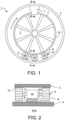
- FIG. 1 is a front view showing a structure of a rotating device according to a first embodiment that is not covered by the appended claims
- FIG. 2 is a partial expanded sectional view at the position A-A of the rotating device shown in FIG. 1 .
- a rotating device 1 is a device, such as a fan or a rotor, having blades 2 and rotating by power for forming a flow of fluid.
- the rotating device 1 can be used for various intended purposes as exemplified below. Therefore, the rotating device 1 can be called by various names according to intended purposes.
- a rotating device included in a watercraft or the like in order to obtain thrust under water is called a screw or a propeller.
- a rotating device included in an aircraft in order to obtain thrust or lift by forming a flow of air is called a fan, a rotor or a propeller.
- a fan housed with a cylindrical duct is called a ducted fan.
- a ducted fan is suspended on a main wing or the like of a fixed wing aircraft in order to obtain thrust or the like.
- a propeller for obtaining thrust or the like is attached to a leading edge of main wing of a fixed wing aircraft or an airship.
- a fan provided in a fuselage, a main wing or the like of a fixed wing aircraft in order to obtain lift is called a lift fan.
- a typical lift fan consists of a ducted fan.
- a rotating device included in a rotorcraft such as a helicopter, is called a rotor or a propeller in many cases.
- a typical helicopter has at least one main rotor for obtaining lift and a tail rotor for adjusting thrust.
- a ducted fan may be used as a tail rotor.
- a rotating device for ventilation such as an electric fan or a ventilation fan
- various fans such as a turbofan and a cooling fan, are also included in an automobile.
- a fan is also included in not only a moving vehicle, such as an automobile, but a turbine, an engine, and the like.
- a turbine itself and a compressor are also one kind of a rotating device.
- the rotating device 1 is a fan, a rotor or a propeller for an aircraft for obtaining thrust or lift will be described mainly.
- the rotating device 1 includes blades 2 but does not include a hub in which a motor is placed. Moreover, spokes for securing the strength are not required necessarily. That is, the rotating device 1 has a hubless structure which has no rotating shaft for transmitting torque to the blades 2 placed radially and is hollow near the rotation center axis.
- a hub is a part or a component part, placed near a rotating axis of a typical circular or radiate rotating device.
- a spoke is a rod member whose length direction is a radial direction of a typical circular rotating device, radially placed in order to couple a circular rim, placed as a structure member at the circumference portion of the rotating device, to a hub placed at the rotating center.
- the rotating device 1 can be composed of the blades 2, a rotating ring 3, a fixed ring 4, motors 5, power transmission mechanisms 6 and a guide mechanism 7 as shown in FIG. 1 .
- Each one end of the blades 2 for forming a flow of fluid, such as air, by rotating around a virtual rotating axis is fixed to the inner surface of the rotating ring 3. Thereby, the blades 2 are placed radially in a space formed inside the rotating ring 3.
- the rotating ring 3 is a ring which can rotate in the circumference direction without a hub for placing a motor inside and spokes for securing strength. Therefore, the rotating ring 3 functions as a rim which transmits torque to the radially placed blades 2 from the outer circumference side.
- a rim is an annular structural member for securing strength.
- the tips of the blades 2 may be overlapped, contacted or coupled to each other, without forming a gap between the tips.
- the tips of the blades 2 are not contacted but overlapped with each other, what is necessary is to twist the tips of the blades 2. Meanwhile, even when the tips of the blades 2 are contacted or coupled to each other, each blade 2 is used only to form a flow of fluid and is not used to secure the strength of the rotating ring 3 although each blade 2 has a structure like a spoke.
- FIG. 3 shows an example of coupling the blades 2 shown in FIG. 1 to each other.
- the tips of the blades 2 may be coupled to each other with a shaft 2A as exemplified in FIG. 3 .
- the shaft 2A which couples the tips of the blade 2 to each other is a mere coupler which does not transfer torque to each blade 2.
- the fixed ring 4 is an annular casing which houses the rotating ring 3 inside which the blades 2 are attached radially.
- the casing may also have a desired cross section shape, such as a rectangular shape, as well as an annular shape.
- the motors 5 are power sources which generate the power for rotating the rotating ring 3.
- the motors 5 must have power according to the weight of the rotating ring 3 to which the blades 2 have been attached radially. For example, when the weight of the rotating ring 3 to which the blades 2 have been attached radially is large like when the blade 2 is large-sized and made of a metal or a fiber-reinforced plastic, sufficient output power is required for the motors 5.
- each motor 5 may be not only an electric motor but a hydraulic motor, a pneumatic motor or a water pressure motor, according to power required for rotating the rotating ring 3 and a usage environment of the rotating device 1.
- Each motor 5 is placed outside the area, including a rotation center, segmented by the rotating ring 3, i.e., outside the area in which the blades 2 are placed radially. This is because the space, including the central axis of the rotating ring 3, separated by the rotating ring 3 is a path of fluid, such as air, and the motor 5 becomes an obstacle of the fluid if the motor 5 is placed.
- each motor 5 can be placed in an annular space formed between the rotating ring 3 and the fixed ring 4 which has a larger diameter than that of the rotating ring 3 as exemplified in FIG. 1 and FIG. 2 .
- each motor 5 can be fixed inside the fixed ring 4 by a support member 8 made of a metal block or the like.
- the three motors 5 have been placed outside the rotating ring 3 and inside the fixed ring 4.
- the number of the motors 5 may be one. That is, at least one motor 5 is included in the rotating device 1.
- Each power transmission mechanism 6 transmits the power from the motor 5 to the rotating ring 3. More specifically, each power transmission mechanism 6 transmits rotational movement from the output shaft 5A of the motor 5 to the rotating ring 3 by transmitting torque output from the output shaft 5A of the motor 5 to the rotating ring 3.
- each power transmission mechanism 6 of at least one gear 9 which transmits the torque output from the output shaft 5A of the motor 5 to the rotating ring 3, from a viewpoint of simplification in structure and obtaining sufficient torque. Therefore, teeth engaged with the gear 9 or the gears 9 are formed also on the outer surface of the rotating ring 3.
- the rotating ring 3 itself can consist of a ring-shaped gear 10 while the power transmission mechanism 6 can be composed of the gear 9 or the gears 9 engaged with the ring-shaped gear 10.
- the torque output from the output shaft 5A of the motor 5 can be transmitted from the gear 9 or the gears 9, composing the power transmission mechanism 6, to the gear 10 composing the rotating ring 3.
- each gear 9 included in the power transmission mechanism 6 can consist of a disk-shaped or cylindrical spur gear.
- Jamming is failure by which the gear 9 does not move mechanically.
- the risk that jamming could arise can be reduced by forming backlash between each gear 9 for transmitting torque to the rotating ring 3 and the ring-shaped gear 10 composing the rotating ring 3.
- the risk that jamming could arise can be reduced by intentionally forming gaps between external teeth formed along the outer circumference of the rotating ring 3 and external teeth formed along the outer circumference of each gear 9.
- a mechanical fuse 11 can be coupled between the output shaft 5A of the motor 5 and each gear 9 included in the power transmission mechanism 6.
- the mechanical fuse 11 is a shaft which breaks when torque exceeds a certain value.
- the mechanical fuse 11 When the mechanical fuse 11 is coupled as a part of the output shaft 5A of the motor 5, the mechanical fuse 11 breaks according to the rise of torque even if the gear 9 stops rotating due to jamming. Therefore, when jamming has arisen, transmission of the power from the corresponding motor 5 to the gear 9 can be cut off promptly. Thereby, the redundancy and the safety of the rotating device 1 can be secured.
- FIG. 4 shows an example of coupling the gear 9 to the output shaft 5A of the motor 5 shown in FIG. 2 through a torque limiter 20.
- the torque limiter 20 may be coupled between the output shaft 5A of the motor 5 and each gear 9, instead of coupling the mechanical fuse 11 to the output shaft 5A of the motor 5.
- the torque limiter 20 is a clutch which cuts off transmission of torque when the torque exceeds a certain value.
- the torque limiter 20 is produced by adjusting torque necessary to slip a one way clutch, which transmits torque only in one way, and has structure in which an inner ring rotates relatively to an outer ring, similarly to a one way clutch.
- each gear 9 may be disposed so that the gears 9 may become point symmetry with regard to the rotation center of the rotating ring 3.
- a position gap of the rotation center of the rotating ring 3 can be prevented so that concentricity of the rotation center and the coaxiality of the rotation axis of the rotating ring 3 can be improved.
- the motors 5 and the gears 9 may be placed so that the weight balance of the rotating device 1 may become satisfactory.
- the motors 5 and the corresponding gears 9 may be placed below locally as exemplified in FIG. 1 . This is the same when the number of the motors 5 is one.
- the guide mechanism 7 is a support device which supports the rotating ring 3 rotatably. In the example shown in FIG. 1 , the guide mechanism 7 has been fixed to the fixed ring 4.
- the guide mechanism 7 can be composed of a guide having rollers rotatably supporting the rotating ring 3, for example.
- the guide mechanism 7 may also be a non-contact-type device utilizing magnetic attraction or the like, instead of a contact-type device.
- FIG. 5 is a partial expanded sectional view at the position B-B which shows a structural example of the guide mechanism 7 shown in FIG. 1 .
- the guide mechanism 7 can have suspension structure in which at least one fixed roller 7A, rolling while contacting with the inner surface of the rotating ring 3, is attached to a frame 7B, for example.
- at least one guide mechanism 7 having such suspension structure can be placed at a desired position so that a vertically upper part of the rotating ring 3 can be supported.
- the weight of the rotating ring 3 can be supported by a pair of the plate-like gears 9 as exemplified in FIG. 2 or at least one cylindrical gear 9 long in the rotating axis direction.
- an upper part of the rotating ring 3 can be supported at the inner surface having no teeth by the fixed roller 7A or the fixed rollers 7A of at least one guide mechanism 7 while a lower part of the rotating ring 3 can be supported at the outer surface having teeth by at least one gear 9.
- the weight of the rotating ring 3 may be supposed only by the gears 9 placed at different positions in the rotation direction of the rotating ring 3 with no guide mechanism 7 when the concentricity required for the rotation center of the rotating ring 3 and the coaxiality required for the rotation axis of the rotating ring 3 are low in a case where the rotation axis of the rotating ring 3 is horizontal.
- each guide mechanism 7 it is realistic to support one end face in the lower side of the rotating ring 3 by at least one guide mechanism 7.
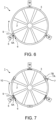
- FIG. 6 is a front view of the rotating device 1 showing an example of transmitting torque from the gears 9 to an end face in the lower side of the rotating ring 3.
- the gears 9 each consisting of a disk-shaped or cylindrical spur gear, as shown in FIG. 6 .
- the gear 10 of the rotating ring 3 engaged with the gears 9 included in the power transmission mechanisms 6 is formed into a ring shape on the end face in the lower side of the rotating ring 3.
- each power transmission mechanism 6 is placed so that the rotating axis may be directed in a radial direction of the rotating ring 3. Then, the motors 5 to which the mechanical fuses 11 or the torque limiters 20 are coupled to the output shafts 5A respectively can be placed outside the rotating ring 3, and the output shafts 5A of the motors 5 can be coupled to the gears 9 respectively, similarly to an example shown in FIG. 2 .
- the weight of the rotating ring 3 may be supported by at least one guide mechanism 7 having desired structure, instead of supporting the weight of the rotating ring 3 only by the gears 9.
- the rotating ring 3 may be floated using a magnetic force so that the weight of the rotating ring 3 can be supported from the lower side.
- FIG. 7 is a front view of the rotating device 1 showing an example of transmitting torque from the gears 9 to an end face in the upper side of the rotating ring 3, and
- FIG. 8 is a partially expanded bottom view of the rotating device 1 showing a structural example of the guide mechanism 7 shown in FIG. 7 .
- the gear 10 When the central axis of the rotating ring 3 is in the vertical direction or close to the vertical direction, the gear 10 may be formed into a ring shape on the end face in the upper side of the rotating ring 3. Meanwhile, a flat ring shaped face or a circle can be formed on the end face in the lower side of the rotating ring 3, without forming teeth having concavity and convexity.
- the weight of the rotating ring 3 can be supported from the lower side by the guide mechanisms 7 each having structure in which a fixed roller 7A or fixed rollers 7A are supported by a frame 7B.
- the gears 9 included in the power transmission mechanisms 6 respectively can be placed in the upper side of the rotating ring 3 so as to be engaged with the gear 10 formed on the end face in the upper side of the rotating ring 3.
- the number of the gears 9 composing the power transmission mechanisms 6 respectively may be one when the redundancy is not given.
- the gears 10 have only to apply torque necessary only for rotation of the rotating ring 3 since the weight of the rotating ring 3 is supported from the lower side by the guide mechanisms 7. Accordingly, the power required for each motor 5 can be reduced.
- the gear 10 may be formed on the outer surface of the rotating ring 3 and the rotating axis of the gear 9 included in each power transmission mechanism 6 may be parallel to the rotating axis of the rotating ring 3, similarly to the example shown in FIG. 1 and FIG. 2 , not only when the weight of the rotating ring 3 is supported from the lower side by the guide mechanisms 7, but also when the weight of the rotating ring 3 is supported from the upper side of the rotating ring 3 by the guide mechanisms 7 of suspension type or the like.
- At least one gear 9 may be placed so that the rotating axis may be directed in a radial direction of the rotating ring 3 when the weight of the rotating ring 3 is supported by at least one guide mechanism 7.
- each gear 9 included in the power transmission mechanisms 6 Although an example of a case where a spur gear was used as each gear 9 included in the power transmission mechanisms 6 was described in the above-mentioned examples, various kinds of gears can be used so that each motor 5 can be placed at a desired position according to a direction of the rotating ring 3 and an intended purpose of the rotating device 1.
- a gear such as a worm gear or a bevel gear, of which the output axis and transfer axis of torque are not the same direction, may be used as at least one gear 9 of the power transmission mechanism 6.
- a gear which rotates a worm wheel with a worm
- a hourglass worm gear and a cylindrical worm gear are typical.
- the ring-shaped gear 10 can be formed on a corresponding surface of the rotating ring 3 according to arrangement and a kind of each gear 9 composing the power transmission mechanism 6 so that the gear 10 can be engaged with each gear 9. That is, the gear 10 may be formed on the outer surface of the rotating ring 3 so that torque may be transmitted from the gears 9 of the power transmission mechanisms 6 to the outer surface of the rotating ring 3 as exemplified in FIG. 1 and FIG. 2 .
- the gear 10 may be formed on a lateral face of the cylindrical rotating ring 3 so that torque may be transmitted from the gears 9 of the power transmission mechanisms 6 to the lateral face of the rotating ring 3 as exemplified in FIG. 6 or FIG. 7 .
- the above-mentioned rotating device 1 having hubless structure can be used for various intended purposes as described above.
- the rotating device 1 can be used as a fan for an aircraft.
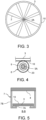
- FIG. 9 shows the first example of an aircraft having the rotating devices 1 shown in FIG. 1 .
- FIG. 10 shows the second example of an aircraft having the rotating devices 1 shown in FIG. 1 .
- FIG. 11 shows the third example of an aircraft having the rotating device 1 shown in FIG. 1 .
- FIG. 12 shows the fourth example of an aircraft having the rotating device 1 shown in FIG. 1 .
- the rotating device 1 having no hub can be used as a fan which composes a turbofan engine or the like attached to a fuselage, a main wing or the like of a fixed wing aircraft 30 in order to obtain thrust.
- the rotating device 1 having no hub can be used as a lift fan attached to a main wing, a fuselage or the like of a fixed wing aircraft 30 as shown in FIG. 10 or FIG. 11 .
- the rotating device 1 can also be used as a ducted fan which composes a tail rotor of a rotor craft 31 as shown in FIG. 12 .
- hydrodynamic efficiency can be improved since the rotating device 1 has no hub which has been disposed at the rotation center of the conventional rotating device.
- the efficiency of generating thrust or lift can be improved, or the force of a generated wind can be increased.
- redundancy can be given to the rotating device 1 by rotating the rotating ring 3 by more than one motor 5 and adopting structure in which transmission of torque to the rotating ring 3 rotating the blades 2 is cut off when the torque applied on the output shaft 5A of the motor 5 exceeds an acceptable range.
- the rotating device 1 can also be used as a fan for an aircraft requiring safety, reliability and redundancy in particular.
- FIG. 13 is a partial sectional view showing a structure of a rotating device according to a second embodiment that is not covered by the appended claims; and FIG. 14 is a perspective view showing a method of disposing two rotating rings shown in FIG. 13 .
- a rotating device 1A in the second embodiment shown in FIG. 13 is different from the rotating device 1 in the first embodiment in a point that the radially placed blades 2 are rotated by each of two rotating rings 3A and 3B placed at different positions in the rotating axis direction.
- the rotating device 1A in the second embodiment has the first rotating ring 3A and the second rotating ring 3B.
- the first rotating ring 3 and the second rotating ring 3B are placed at different positions in a common central axis direction so that the first rotating ring 3 and the second rotating ring 3B may rotate around the central axes which are on the same common straight line as shown in FIG. 14 .
- Each power transmission mechanism 6 is configured to rotate the first rotating ring 3A and the second rotating ring 3B in directions opposite to each other by transmitting torque, output from the motor 5, to each of the first rotating ring 3A and the second rotating ring 3B as shown in FIG. 13 .
- the common motor 5 can have two output shafts 5A outputting torque in directions opposite to each other. Then, one output shaft 5A of the motor 5 can be coupled to the first rotating ring 3A through the gear 9 while the other output shaft 5A of the motor 5 can be coupled to the second rotating ring 3B through the gear 9.
- first rotating ring 3 A and the second rotating ring 3B may be rotated in directions opposite to each other with separate motors 5. Nevertheless, when the first rotating ring 3A and the second rotating ring 3B are rotated in directions opposite to each other with the common motor 5, it becomes easy to coincide the rotating speed of the first rotating ring 3A with that of the second rotating ring 3B, and to synchronize rotational movement of the first rotating ring 3A with that of the second rotating ring 3B.
- the rotating device 1A can be functioned as contra-rotating propellers or contra-rotating fans. Therefore, wind force, thrust, lift or the like generated by the rotating device 1A can be made large.
- disposing a bearing between the first rotating ring 3A and the second rotating ring 3B allows rotating the first rotating ring 3A and the second rotating ring 3B in directions opposite to each other while supporting the weight of the rotating ring 3 in the upper side.
- the gears 9 may be disposed between the first rotating ring 3A and the second rotating ring 3B so that the rotating axis directions of the gears 9 may be radial directions of the first rotating ring 3A and the second rotating ring 3B, similarly to the examples shown in FIG. 6 and FIG. 7 .
- a bearing may be disposed between the first rotating ring 3A and the second rotating ring 3B while separate gears 9 may be disposed in both sides of a contra-rotating ring unit, configured by coupling the first rotating ring 3A to the second rotating ring 3B with the bearing, so that the rotating axis directions of the separate gears 9 may be radial directions of the first rotating ring 3A and the second rotating ring 3B.
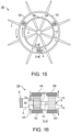
- FIG. 15 is a front view showing a structure of a rotating device according to a third embodiment, according to the present invention
- FIG. 16 is a partial expanded sectional view at the position C-C of the rotating device shown in FIG. 15 .
- a rotating device 1B in the third embodiment shown in FIG. 15 and FIG. 16 is different from the rotating device 1A in the second embodiment in a point that the radially placed blades 2 are rotated by each of four rotating rings 3A, 3B, 3C and 3D placed at different positions in the rotating radial direction in addition to the rotating axis direction.
- the rotating rings 3 can also be placed at different positions not only in the rotating axis direction but in the rotating radial direction as shown in FIG. 15 and FIG. 16 .
- the rotating rings 3A, 3B, 3C and 3D have been placed at different positions in the rotating axis direction and in the rotating radial direction. Therefore, the number of the rotating rings 3A, 3B, 3C and 3D is four.
- the first rotating ring 3A and the third rotating ring 3B of which diameters are almost the same are placed at different positions in the rotating axis direction.
- the first rotating ring 3A and the second rotating ring 3C of which diameters are different from each other are placed at different positions in the rotating radial direction so that the first rotating ring 3A is inside while the second rotating ring 3C is outside.
- the third rotating ring 3B and the fourth rotating ring 3D of which diameters are different from each other are placed at different positions in the rotating radial direction so that the third rotating ring 3B is inside while the fourth rotating ring 3D is outside. Therefore, the inside diameter of the second rotating ring 3C is larger than the outside diameter of the first rotating ring 3A. Similarly, the inside diameter of the fourth rotating ring 3D is larger than the outside diameter of the third rotating ring 3B.
- the blades 2 are radially attached on each of the inner surfaces of the inside first rotating ring 3A and third rotating ring 3B. Meanwhile, the blades 2 are radially attached to each of the outer surfaces of the outside second rotating ring 3C and fourth rotating ring 3D. Then, at least one motor 5 and gears 9 are placed in an annular space formed between the inside first and third rotating rings 3A and 3B, and the outside second and fourth rotating rings 3C and 3D so that the gears 9 can transmit torque output from each motor 5 to each of the first rotating ring 3A, the third rotating ring 3B, the second rotating ring 3C and the fourth rotating ring 3.
- Each power transmission mechanism 6 is configured to rotate the inside first rotating ring 3A and third rotating ring 3B, disposed in parallel in the rotating axis direction, in directions opposite to each other, similarly to the second embodiment. Similarly, each power transmission mechanism 6 is configured to rotate the outside second rotating ring 3C and fourth rotating ring 3D, disposed in parallel in the rotating axis direction, in directions opposite to each other.
- each power transmission mechanism 6 is configured to rotate the inside first rotating ring 3A and the outside second rotating ring 3C, disposed concentrically, in directions opposite to each other.
- each power transmission mechanism 6 is configured to rotate the inside third rotating ring 3B and the outside fourth rotating ring 3D, disposed concentrically, in directions opposite to each other.
- the gear 10 can be formed on each of the outer surface of the inside first rotating ring 3A and the inner surface of the outside second rotating ring 3C as exemplified in FIG. 16 .
- the gear 9 included in the power transmission mechanism 6 can be disposed so that the rotating axis of the gear 9 may be parallel to the rotating axes of the first rotating ring 3A and the second rotating ring 3C, and the gear 9 can be engaged with both of the gear 10 formed on the outer surface of the first rotating ring 3A and the gear 10 formed on the inner surface of the second rotating ring 3C.
- the gear 10 can be formed on each of the outer surface of the inside third rotating ring 3B and the inner surface of the outside fourth rotating ring 3D.
- the gear 9 included in the power transmission mechanism 6 can be disposed so that the rotating axis of the gear 9 may be parallel to the rotating axes of the third rotating ring 3B and the fourth rotating ring 3D, and the gear 9 can be engaged with both of the gear 10 formed on the outer surface of the third rotating ring 3B and the gear 10 formed on the inner surface of the fourth rotating ring 3D.
- first rotating ring 3A and the second rotating ring 3C can be reversely rotated relatively by transmitting torque from the common gear 9 to the inside first rotating ring 3A and the outside second rotating ring 3C in directions opposite to each other.
- third rotating ring 3B and the fourth rotating ring 3D can be reversely rotated relatively by transmitting torque from the common gear 9 to the inside third rotating ring 3B and the outside fourth rotating ring 3D in directions opposite to each other.
- a coaxial contra-rotating motor in which two output shafts 5A outputting torque in directions opposite to each other have been disposed coaxially can be used as each motor 5 as exemplified in FIG. 16 . Then, it becomes possible to rotate the gear 9 for rotating the first rotating ring 3A and the second rotating ring 3C in opposite directions by transmitting torque in opposite directions, and the gear 9 for rotating the third rotating ring 3B and the fourth rotating ring 3D in opposite directions by transmitting torque in opposite directions, with the common motor 5.
- At least one of the mechanical fuse 11 and the torque limiter 20 can be coupled to the output shafts 5A of the motor 5 in order to secure redundancy.
- the gear 9 for rotating the first rotating ring 3A and the second rotating ring 3C is coupled to the outside cylindrical output shaft 5A of the motor 5 through the torque limiter 20.
- the mechanical fuse 11 is included in the inside round bar-shaped output shaft 5A of the motor 5, coupled to the gear 9 for rotating the third rotating ring 3B and the fourth rotating ring 3D.
- the torque limiter 20 may be used instead of the mechanical fuse 11, and conversely, the mechanical fuse 11 may be used instead of the torque limiter 20.
- the motor 5 having two round bar-shaped output shafts 5A in both sides may be used as exemplified in FIG. 13
- using the motor 5 having the columnar output shaft 5A inside the cylindrical output shaft 5A as exemplified in FIG. 16 makes it possible to dispose the support member 8, for supporting the motor 5, at such a position that the support member 8 does not interfere with the path of fluid as much as possible.
- a set of the first rotating ring 3A and the third rotating ring 3B, and a set of the second rotating ring 3C and the fourth rotating ring 3D can be rotated in directions opposite to each other by transmitting the torque output from the motor 5 or the motors 5 to each of the outer surfaces of the inside first rotating ring 3A and third rotating ring 3B and the inner surfaces of the outside second rotating ring 3C and fourth rotating ring 3D, with at least one power transmission mechanism 6 composed of the gears 9.
- the rotating device 1B can be made to function as not only contra-rotating propellers or contra-rotating fans of which two sets of the blades 2 radially disposed at different positions in the rotating axis direction are rotated in directions opposite to each other, but also contra-rotating propellers or contra-rotating fans of which two sets of the blades 2 radially disposed at different positions in the rotating radial direction are rotated in directions opposite to each other.
- the gears 9 may be disposed so that the rotating axes may be in the rotating radial directions of the rotating rings 3A, 3B, 3C and 3D, and torque of each gear 9 can be transmitted to the end faces of the rotating rings 3A, 3B, 3C and 3D.
- At least one gear 9 may be disposed between the first rotating ring 3A and the third rotating ring 3B, and between the second rotating ring 3C and the fourth rotating ring 3D so that each rotating axis may be in the rotating radial direction of the rotating rings 3A, 3B, 3C and 3D.
- a contra-rotating ring unit may be composed by coupling bearings between the first rotating ring 3A and the third rotating ring 3B, and between the second rotating ring 3C and the fourth rotating ring 3D respectively, and the separate gears 9 may be disposed in both sides of the contra-rotating ring unit so that the rotating axes may be in the rotating radial directions of the rotating rings 3A, 3B, 3C and 3D.
- the rotating device 1B may be composed of only the outside second rotating ring 3C and fourth rotating ring 3D by omitting the inside first rotating ring 3A and third rotating ring 3B, which is not covered by the appended claims.
- the blades 2 may be attached to the outer surfaces of the two rotating rings 3.
- the rotating device 1B may be composed of only the inside first rotating ring 3A and the outside second rotating ring 3C by omitting the inside third rotating ring 3B and the outside fourth rotating ring 3D.
- the inside first rotating ring 3A and the outside second rotating ring 3C may be rotated in the same direction.
- the inside third rotating ring 3B and the outside fourth rotating ring 3D may be rotated in the same direction.
- the rotating rings 3 disposed at different positions in the rotating axis direction may be reversely rotated relatively to each other while the rotating rings 3 disposed at different positions in the rotating radial direction may be rotated in the same direction.
- FIG. 17 shows a structural example of the motor 5 and the gears 9 in a case of rotating, in the same direction, the rotating rings 3 disposed at positions different from each other in the rotating radial direction, out of the rotating rings 3A, 3B, 3C and 3D shown in FIG. 15 .
- FIG. 17 is a partial expanded sectional view at the position corresponding to the position C-C of FIG. 15 .
- disk-shaped or cylindrical additional gears 9, consisting of external gears respectively engaged with the gears 9 whose rotating axes are on the straight line passing through the output shaft 5A of the motor 5, can be disposed.
- the inside first rotating ring 3A and the outside second rotating ring 3C can be rotated in the same direction while the inside third rotating ring 3B and the outside fourth rotating ring 3D can be rotated in the same direction.
- the two gears 9 whose rotating axes are not on the straight line passing through the output shaft 5A of the motor 5 can be attached to a desired common structural object with contra-rotating shafts composed of a cylindrical rotating shaft and a bar-shaped rotating shaft inserted inside the cylindrical rotating shaft.
- the two gears 9 whose rotating axes are not on the straight line passing through the output shaft 5A of the motor 5 may be attached to desired separated structural objects respectively by disposing two simple bar-shaped rotating shafts on the same straight line outward so that they may not interfere with each other.
- each of the rotating rings 3A, 3B, 3C and 3D can be rotated at a rotating speed corresponding to a gear ratio of the two gears 9 engaged with each other.
- the sizes of the gears 9 have been determined so that the rotating speeds of the inside first rotating ring 3A and the inside third rotating ring 3B whose diameters are relatively small may be respectively larger than the rotating speeds of the outside second rotating ring 3C and the outside fourth rotating ring 3D whose diameters are relatively large.
- another motor 5 and other gears 9 for rotating the outside second rotating ring 3C and the outside fourth rotating ring 3D may be prepared independently.
- the rotating speeds of the rotating rings 3A, 3B, 3C and 3D can be variably adjusted by controlling the motors 5.
- the rotating device 1B may be composed of a single rotating ring 3 having the blades 2 disposed radially on the outer surface, which is not covered by the appended claims.
- the blades 2 may be attached to the outer surface of the rotating ring 3.
- a fixed ring may be disposed as a support member for fixing the motors 5 or the like with the inside of the rotating ring 3.
- the blades 2 can be radially attached to at least one of the outer surface and the inner surface of at least one rotating ring 3, and power from at least one motor 5 can be transmitted to at least one of the outer surface, the inner surface and the side surfaces of the rotating ring 3 with at least one power transmission mechanism 6 having at least one gear 9.
- the rotating rings 3 are disposed at different positions in at least one direction of the central axis direction of the rotating rings 3 and the radial direction of the rotating rings 3. Then, a rotating device having such a hubless structure can be used for various intended purposes.
- FIG. 18 is a partial sectional view showing a structure of a rotating device according to a fourth embodiment according to the present invention.
- the rotating device 1C in the fourth embodiment shown in FIG. 18 is different from the rotating device 1B in the third embodiment in a point that at least one clutch mechanism 40 which switches transmission and cutoff of power output from the motor 5 to at least one rotating ring 3 is included.
- the rotating device 1C in the fourth embodiment has at least one clutch mechanisms 40.
- Each clutch mechanism 40 is a device which switches transmission and cutoff of power output from the motor 5 to at least one of the rotating rings 3A, 3B, 3C and 3D.
- Each clutch mechanism 40 can be composed of a slide mechanism, such as a linear guide, which moves the motor 5 and the gears 9 in parallel in the rotating radial direction of the rotating rings 3A, 3B, 3C and 3D as shown in FIG. 18 .
- the distance between the gears 10 formed on the outer surfaces of the inside first and third rotating rings 3A and 3B, and the gears 10 formed on the inner surfaces of the outside second and fourth rotating rings 3C and 3D can be made a distance obtained by adding a parallel moving amount of the motor 5 and the gears 9 by the clutch mechanism 40 with the diameter of the gears 9 for rotating the rotating rings 3A, 3B, 3C and 3D.
- the distance between the gears 10 formed on the outer surfaces of the inside first and third rotating rings 3A and 3B, and the gears 10 formed on the inner surfaces of the outside second and fourth rotating rings 3C and 3D can be made longer than the diameter of the gears 9 for rotating the rotating rings 3A, 3B, 3C and 3D so that the gears 9 can be moved in parallel in the rotating radial direction of the rotating rings 3A, 3B, 3C and 3D by the clutch mechanism 40.
- the gears 9 can be engaged with either the gears 10 formed on the outer surfaces of the inside first and third rotating rings 3A and 3B or the gears 10 formed on the inner surfaces of the outside second and fourth rotating rings 3C and 3D, by operation of the clutch mechanism 40.
- the rotating rings 3 to be rotated can be switched between the inside first and third rotating rings 3A and 3B, and the outside second and fourth rotating rings 3C and 3D.
- the clutch mechanism 40 may also be configured to switch rotation and stop of the rotating rings 3A, 3B, 3C and 3D individually. Therefore, the clutch mechanism 40 can be included in the rotating device 1C regardless of the number of the rotating rings 3.
- FIG. 19 is a front view showing a structure of a rotating device according to a fifth embodiment that is not covered by the appended claims.
- a rotating device 1D in the fifth embodiment shown in FIG. 19 is different from the rotating device 1 in the first embodiment in a point that at least one crawler 50 is included in the power transmission mechanism 6.
- Other configurations and actions of the rotating device 1D in the fifth embodiment does not substantially differ from those of the rotating device 1 in the first embodiment. Therefore, the same signs are attached to the same elements and the corresponding elements, and explanation thereof is omitted.
- the crawler 50 may be used as the power transmission mechanism 6 which transmits power output from the motor 5 to the rotating ring 3, as well as the gear 9 as explained in the above-mentioned other embodiments. Specifically, at least one crawler 50 can be disposed so as to contact with the outer surface of the rotating ring 3. Thereby, torque output from the motor 5 can be transmitted to the outer surface of the rotating ring 3 by the crawler 50.
- Typical examples of the crawler 50 include a power transmission belt moving by frictional forces with rollers and a chain moving by rotation of sprockets. Also, when the crawler 50 is used, redundancy can be obtained by rotating the common rotating ring 3 with a plurality of the crawlers 50 as exemplified in FIG. 19 .
- At least one rotating ring 3 may be rotated using both the gear 9 and the crawler 50. That is, the power transmission mechanism 6 can be composed of at least one of the gear 9 engaged with the gear 10 formed on the rotating ring 3 and the crawler 50 contacting with the rotating ring 3.
- a rotating device having no blades 2 may be composed of at least one rotating ring 3.
- a rotating device having no rotation shaft can be used as a tire wheel for an automobile. That is, the rotating ring 3 having no hub and no spokes can be used as a rim, and a tire for an automobile can be fixed to the outside of the rotating ring 3.
Description
- Embodiments described herein relate generally to a rotating device and an aircraft.
- Conventionally, a fan is used as a rotating device having the power for air blow or obtaining thrust (for example, refer to Japanese Patent Application Publication
JP 2015-501 751 A - However, a hub is always exposed to a flow of fluid induced by rotation of blades. Moreover, a path of the fluid is narrowed due to arrangement of a hub. Therefore, a hub causes the increase in a fluid resistance and a pressure loss. As a result, a hub is a deterioration factor in transfer efficiency of fluid.
- For example, when a fan is intended for air blow, a hub is a deterioration factor in the generation efficiency of a wind. Meanwhile, when a fan is a ducted fan of an aircraft for obtaining thrust, a hub is a deterioration factor in the generation efficiency of the thrust.
- On the other hand, a rotor for an aircraft having a structure in which a hub is not disposed has been also proposed. As an example, a floating mechanism, composed of two rotating rings disposed one above the other and blades radially attached to the outer surfaces of the rotating rings, which generates lift by rotating the two rotating rings reversely to each other, has been proposed for a V/STOL (vertical and/or short take-off and landing) aircraft (for example, refer to Japanese Patent Application Publication
JP 2015-501 751 A - As for a rotating device having the power, such as a fan, it is preferable not to dispose any structural object, which may obstruct a flow of fluid, as well as a hub around a rotation center in order to achieve the purpose of the rotating device more efficiently.
- For example, when a fan is intended for air blow, it leads to improvement in air blow efficiency to dispose no structural objects other than blades around a rotation center. Meanwhile, when a fan is a ducted fan of an aircraft, it leads to improvement in thrust to dispose no structural objects other than blades around a rotation center. The background art may also be found in
GB 2 423 509AUS 4 787 573 A ,US 9 555 879 B1 CN 108 361 124 A ,US 2012/175179 A1 , andWO 2013/182708 A1 . - Accordingly, an object of the present invention is to provide a rotating device wherein parts are reduced which should be disposed near a rotation center of a rotating device, such as a fan, which rotates by power, as much as possible.
- The invention is defined by the independent claim.
- Further, according to one embodiment, an aircraft includes the above-mentioned rotating device.
- In the accompanying drawings:
- FIG. 1
- is a front view showing a structure of a rotating device according to a first embodiment that is not covered by the appended claims;
- FIG. 2
- is a partial expanded sectional view at the position A-A of the rotating device shown in
FIG. 1 ; - FIG. 3
- shows an example of coupling the blades shown in
FIG. 1 to each other; - FIG. 4
- shows an example of coupling the gear to the output shaft of the motor shown in
FIG. 2 through a torque limiter; - FIG. 5
- is a partial expanded sectional view at the position B-B which shows a structural example of the guide mechanism shown in
FIG. 1 ; - FIG. 6
- is a front view of the rotating device showing an example of transmitting torque from the gears to an end face in the lower side of the rotating ring;
- FIG. 7
- is a front view of the rotating device showing an example of transmitting torque from the gears to an end face in the upper side of the rotating ring;
- FIG. 8
- is a partially expanded bottom view of the rotating device showing a structural example of the guide mechanism shown in
FIG. 7 ; - FIG. 9
- shows a first example of an aircraft having the rotating device shown in
FIG. 1 ; - FIG. 10
- shows a second example of an aircraft having the rotating device shown in
FIG. 1 ; - FIG. 11
- shows a third example of an aircraft having the rotating device shown in
FIG. 1 ; - FIG. 12
- shows a fourth example of an aircraft having the rotating device shown in
FIG. 1 ; - FIG. 13
- is a partial sectional view showing a structure of a rotating device according to a second embodiment that is not covered by the appended claims;
- FIG. 14
- is a perspective view showing a method of disposing two rotating rings shown in
FIG. 13 ; - FIG. 15
- is a front view showing a structure of a rotating device according to a third embodiment, according to the present invention;
- FIG. 16
- is a partial expanded sectional view at the position C-C of the rotating device shown in
FIG. 15 ; - FIG. 17
- shows a structural example of the motor and the gears in a case of rotating, in the same direction, the rotating rings disposed at positions different from each other in the rotating radial direction, out of the rotating rings shown in
FIG. 15 ; - FIG. 18
- is a partial sectional view showing a structure of a rotating device according to a fourth embodiment of the present invention; and
- FIG. 19
- is a front view showing a structure of a rotating device according to a fifth embodiment that is not covered by the appended claims.
- A rotating device and an aircraft according to embodiments of the present invention will be described with reference to the accompanying drawings.
-
FIG. 1 is a front view showing a structure of a rotating device according to a first embodiment that is not covered by the appended claims, andFIG. 2 is a partial expanded sectional view at the position A-A of the rotating device shown inFIG. 1 . - A
rotating device 1 is a device, such as a fan or a rotor, havingblades 2 and rotating by power for forming a flow of fluid. Therotating device 1 can be used for various intended purposes as exemplified below. Therefore, therotating device 1 can be called by various names according to intended purposes. - In general, a rotating device included in a watercraft or the like in order to obtain thrust under water is called a screw or a propeller. Meanwhile, a rotating device included in an aircraft in order to obtain thrust or lift by forming a flow of air is called a fan, a rotor or a propeller. In particular, a fan housed with a cylindrical duct is called a ducted fan.
- For example, a ducted fan is suspended on a main wing or the like of a fixed wing aircraft in order to obtain thrust or the like. Alternatively, a propeller for obtaining thrust or the like is attached to a leading edge of main wing of a fixed wing aircraft or an airship. Moreover, a fan provided in a fuselage, a main wing or the like of a fixed wing aircraft in order to obtain lift is called a lift fan. A typical lift fan consists of a ducted fan.
- Meanwhile, a rotating device included in a rotorcraft, such as a helicopter, is called a rotor or a propeller in many cases. A typical helicopter has at least one main rotor for obtaining lift and a tail rotor for adjusting thrust. A ducted fan may be used as a tail rotor.
- On the other hand, a rotating device for ventilation, such as an electric fan or a ventilation fan, is called a fan in many cases. Meanwhile, various fans, such as a turbofan and a cooling fan, are also included in an automobile. A fan is also included in not only a moving vehicle, such as an automobile, but a turbine, an engine, and the like. Moreover, a turbine itself and a compressor are also one kind of a rotating device.
- Hereinafter, an example of a case where the
rotating device 1 is a fan, a rotor or a propeller for an aircraft for obtaining thrust or lift will be described mainly. - The
rotating device 1 includesblades 2 but does not include a hub in which a motor is placed. Moreover, spokes for securing the strength are not required necessarily. That is, therotating device 1 has a hubless structure which has no rotating shaft for transmitting torque to theblades 2 placed radially and is hollow near the rotation center axis. - Note that, a hub is a part or a component part, placed near a rotating axis of a typical circular or radiate rotating device. Meanwhile, a spoke is a rod member whose length direction is a radial direction of a typical circular rotating device, radially placed in order to couple a circular rim, placed as a structure member at the circumference portion of the rotating device, to a hub placed at the rotating center.
- The
rotating device 1 can be composed of theblades 2, arotating ring 3, a fixedring 4,motors 5,power transmission mechanisms 6 and aguide mechanism 7 as shown inFIG. 1 . - Each one end of the
blades 2 for forming a flow of fluid, such as air, by rotating around a virtual rotating axis is fixed to the inner surface of therotating ring 3. Thereby, theblades 2 are placed radially in a space formed inside therotating ring 3. - The
rotating ring 3 is a ring which can rotate in the circumference direction without a hub for placing a motor inside and spokes for securing strength. Therefore, therotating ring 3 functions as a rim which transmits torque to the radially placedblades 2 from the outer circumference side. A rim is an annular structural member for securing strength. - Note that, the tips of the
blades 2 may be overlapped, contacted or coupled to each other, without forming a gap between the tips. When the tips of theblades 2 are not contacted but overlapped with each other, what is necessary is to twist the tips of theblades 2. Meanwhile, even when the tips of theblades 2 are contacted or coupled to each other, eachblade 2 is used only to form a flow of fluid and is not used to secure the strength of therotating ring 3 although eachblade 2 has a structure like a spoke. -
FIG. 3 shows an example of coupling theblades 2 shown inFIG. 1 to each other. - The tips of the
blades 2 may be coupled to each other with ashaft 2A as exemplified inFIG. 3 . Theshaft 2A which couples the tips of theblade 2 to each other is a mere coupler which does not transfer torque to eachblade 2. - The fixed
ring 4 is an annular casing which houses therotating ring 3 inside which theblades 2 are attached radially. When the cross sectional shape of therotating device 1 need not be circular, the casing may also have a desired cross section shape, such as a rectangular shape, as well as an annular shape. - The
motors 5 are power sources which generate the power for rotating therotating ring 3. Themotors 5 must have power according to the weight of therotating ring 3 to which theblades 2 have been attached radially. For example, when the weight of therotating ring 3 to which theblades 2 have been attached radially is large like when theblade 2 is large-sized and made of a metal or a fiber-reinforced plastic, sufficient output power is required for themotors 5. - Conversely, when the weight of the
rotating ring 3 to which theblades 2 have been attached radially is very small like when theblade 2 is small-sized and made of a plastic, the output power required for themotors 5 is small. - Therefore, each
motor 5 may be not only an electric motor but a hydraulic motor, a pneumatic motor or a water pressure motor, according to power required for rotating therotating ring 3 and a usage environment of therotating device 1. - Each
motor 5 is placed outside the area, including a rotation center, segmented by therotating ring 3, i.e., outside the area in which theblades 2 are placed radially. This is because the space, including the central axis of therotating ring 3, separated by therotating ring 3 is a path of fluid, such as air, and themotor 5 becomes an obstacle of the fluid if themotor 5 is placed. - For that reason, the
motors 5 can be placed in an annular space formed between therotating ring 3 and the fixedring 4 which has a larger diameter than that of therotating ring 3 as exemplified inFIG. 1 and FIG. 2 . For example, eachmotor 5 can be fixed inside the fixedring 4 by asupport member 8 made of a metal block or the like. - In the example shown in
FIG. 1 , the threemotors 5 have been placed outside therotating ring 3 and inside the fixedring 4. Note that, the number of themotors 5 may be one. That is, at least onemotor 5 is included in therotating device 1. - When the power for rotating the one common
rotating ring 3 is generated by themotors 5, it becomes possible to continue rotation of therotating ring 3 by transmitting the power from at least any one of themotors 5 to therotating ring 3 even when trouble that the power from onemotor 5 is not transmitted to therotating ring 3 occurs. That is, redundancy can be given to therotating device 1 by rotating the commonrotating ring 3 andblades 2 by themotors 5. - Each
power transmission mechanism 6 transmits the power from themotor 5 to therotating ring 3. More specifically, eachpower transmission mechanism 6 transmits rotational movement from theoutput shaft 5A of themotor 5 to therotating ring 3 by transmitting torque output from theoutput shaft 5A of themotor 5 to therotating ring 3. - It is practical to compose each
power transmission mechanism 6 of at least onegear 9 which transmits the torque output from theoutput shaft 5A of themotor 5 to therotating ring 3, from a viewpoint of simplification in structure and obtaining sufficient torque. Therefore, teeth engaged with thegear 9 or thegears 9 are formed also on the outer surface of therotating ring 3. - That is, the
rotating ring 3 itself can consist of a ring-shapedgear 10 while thepower transmission mechanism 6 can be composed of thegear 9 or thegears 9 engaged with the ring-shapedgear 10. Thereby, the torque output from theoutput shaft 5A of themotor 5 can be transmitted from thegear 9 or thegears 9, composing thepower transmission mechanism 6, to thegear 10 composing therotating ring 3. - When the power and torque output from the
output shaft 5A of themotor 5 are transmitted to the outer surface of therotating ring 3 as exemplified inFIG. 1 and FIG. 2 , therotating ring 3 consists of a ring-shaped external gear. Therefore, eachgear 9 included in thepower transmission mechanism 6 can consist of a disk-shaped or cylindrical spur gear. - In order to secure redundancy by generating the power for rotating the common
rotating ring 3 with themotors 5, it is appropriate to transmit the pieces of power, generated by themotors 5, separately to the commonrotating ring 3 by thepower transmission mechanisms 6 respectively. Therefore, it is appropriate to couple theoutput shafts 5A of themotors 5 to theseparate gears 9 respectively. - When the power is transmitted by at least one
gear 9, it leads to improvement in reliability and safety to prevent jamming. Jamming is failure by which thegear 9 does not move mechanically. For example, the risk that jamming could arise can be reduced by forming backlash between eachgear 9 for transmitting torque to therotating ring 3 and the ring-shapedgear 10 composing therotating ring 3. - That is, the risk that jamming could arise can be reduced by intentionally forming gaps between external teeth formed along the outer circumference of the
rotating ring 3 and external teeth formed along the outer circumference of eachgear 9. - Furthermore, a
mechanical fuse 11 can be coupled between theoutput shaft 5A of themotor 5 and eachgear 9 included in thepower transmission mechanism 6. Themechanical fuse 11 is a shaft which breaks when torque exceeds a certain value. - When the
mechanical fuse 11 is coupled as a part of theoutput shaft 5A of themotor 5, themechanical fuse 11 breaks according to the rise of torque even if thegear 9 stops rotating due to jamming. Therefore, when jamming has arisen, transmission of the power from thecorresponding motor 5 to thegear 9 can be cut off promptly. Thereby, the redundancy and the safety of therotating device 1 can be secured. -
FIG. 4 shows an example of coupling thegear 9 to theoutput shaft 5A of themotor 5 shown inFIG. 2 through atorque limiter 20. - As exemplified in
FIG. 4 , thetorque limiter 20 may be coupled between theoutput shaft 5A of themotor 5 and eachgear 9, instead of coupling themechanical fuse 11 to theoutput shaft 5A of themotor 5. Thetorque limiter 20 is a clutch which cuts off transmission of torque when the torque exceeds a certain value. - The
torque limiter 20 is produced by adjusting torque necessary to slip a one way clutch, which transmits torque only in one way, and has structure in which an inner ring rotates relatively to an outer ring, similarly to a one way clutch. - When the
torque limiter 20 is coupled to theoutput shaft 5A of themotor 5, transmission of torque is cut off according to rise in the torque even if thegear 9 stops rotating due to jamming. Therefore, when jamming has arisen, transmission of the power from thecorresponding motor 5 to thegear 9 can be promptly cut off. Thereby, the redundancy and the safety of therotating device 1 can be secured. - When not less than two
gears 9 are prepared in order to rotate therotating ring 3, eachgear 9 may be disposed so that thegears 9 may become point symmetry with regard to the rotation center of therotating ring 3. When not less than threegears 9 are disposed so that thegears 9 may become point symmetry with regard to the rotation center of therotating ring 3, a position gap of the rotation center of therotating ring 3 can be prevented so that concentricity of the rotation center and the coaxiality of the rotation axis of therotating ring 3 can be improved. - Even when not less than three
gears 9 are disposed so that thegears 9 may not become point symmetry with regard to the rotation center of therotating ring 3, a position gap in a radial direction of therotating ring 3 can be prevented as long as the not less than threegears 9 are disposed so that at least onegear 9 may lie in each of both sides which sandwich the diameter at any position of therotating ring 3. - When the
motor 5 with large weight is placed at a high position in a case where the rotation axis of therotating ring 3 is not in the vertical direction, the center of gravity of therotating device 1 moves to a high position, and the stability of therotating device 1 deteriorates. Accordingly, themotors 5 and thegears 9 may be placed so that the weight balance of therotating device 1 may become satisfactory. - For example, when the central axis of the
rotating ring 3 is approximately horizontal, themotors 5 and the correspondinggears 9 may be placed below locally as exemplified inFIG. 1 . This is the same when the number of themotors 5 is one. - When a local portion of the
rotating ring 3 is engaged with thegear 9 or thegears 9, therotating ring 3 may become unstable since a portion of therotating ring 3 away from thegear 9 or thegears 9 are not be supported. Accordingly, therotating ring 3 may be supported by theguide mechanism 7, as needed. Theguide mechanism 7 is a support device which supports therotating ring 3 rotatably. In the example shown inFIG. 1 , theguide mechanism 7 has been fixed to the fixedring 4. - The
guide mechanism 7 can be composed of a guide having rollers rotatably supporting therotating ring 3, for example. As a matter of course, theguide mechanism 7 may also be a non-contact-type device utilizing magnetic attraction or the like, instead of a contact-type device. -
FIG. 5 is a partial expanded sectional view at the position B-B which shows a structural example of theguide mechanism 7 shown inFIG. 1 . - As exemplified in
FIG. 5 , theguide mechanism 7 can have suspension structure in which at least one fixedroller 7A, rolling while contacting with the inner surface of therotating ring 3, is attached to aframe 7B, for example. When the central axis of therotating ring 3 is approximately horizontal, at least oneguide mechanism 7 having such suspension structure can be placed at a desired position so that a vertically upper part of therotating ring 3 can be supported. - On the other hand, as for a vertically lower part of the
rotating ring 3, the weight of therotating ring 3 can be supported by a pair of the plate-like gears 9 as exemplified inFIG. 2 or at least onecylindrical gear 9 long in the rotating axis direction. - That is, when the angle between the central axis of the
rotating ring 3 and the horizontal direction is within ± 45°, for example, like a case where therotating device 1 is a ducted fan for an aircraft for obtaining thrust, an upper part of therotating ring 3 can be supported at the inner surface having no teeth by the fixedroller 7A or the fixedrollers 7A of at least oneguide mechanism 7 while a lower part of therotating ring 3 can be supported at the outer surface having teeth by at least onegear 9. - Note that, the weight of the
rotating ring 3 may be supposed only by thegears 9 placed at different positions in the rotation direction of therotating ring 3 with noguide mechanism 7 when the concentricity required for the rotation center of therotating ring 3 and the coaxiality required for the rotation axis of therotating ring 3 are low in a case where the rotation axis of therotating ring 3 is horizontal. - In a case where the central axis of the
rotating ring 3 rotating theblades 2 is in the vertical direction or close to the vertical direction, such as a case where an angle between the central axis of therotating ring 3 and the vertical direction is within ± 45°, one end face of therotating ring 3 becomes a lower side. - In that case, it is realistic to support one end face in the lower side of the
rotating ring 3 by at least oneguide mechanism 7. When the central axis of therotating ring 3 is in the vertical direction or close to the vertical direction, not only eachguide mechanism 7 but eachgear 9 may be placed in the lower side of one end face of therotating ring 3. -
FIG. 6 is a front view of therotating device 1 showing an example of transmitting torque from thegears 9 to an end face in the lower side of therotating ring 3. - When the central axis of the
rotating ring 3 is in the vertical direction or close to the vertical direction, torque can be transmitted to the end face in the lower side of therotating ring 3 while supporting the weight of therotating ring 3 using thegears 9 each consisting of a disk-shaped or cylindrical spur gear, as shown inFIG. 6 . In this case, thegear 10 of therotating ring 3 engaged with thegears 9 included in thepower transmission mechanisms 6 is formed into a ring shape on the end face in the lower side of therotating ring 3. - Meanwhile, the
gear 9 included in eachpower transmission mechanism 6 is placed so that the rotating axis may be directed in a radial direction of therotating ring 3. Then, themotors 5 to which themechanical fuses 11 or thetorque limiters 20 are coupled to theoutput shafts 5A respectively can be placed outside therotating ring 3, and theoutput shafts 5A of themotors 5 can be coupled to thegears 9 respectively, similarly to an example shown inFIG. 2 . - In addition, the weight of the
rotating ring 3 may be supported by at least oneguide mechanism 7 having desired structure, instead of supporting the weight of therotating ring 3 only by thegears 9. When all or a part of the weight of therotating ring 3 is supported by at least oneguide mechanism 7, output torque required for eachgear 9 to rotate therotating ring 3 can be reduced. For example, therotating ring 3 may be floated using a magnetic force so that the weight of therotating ring 3 can be supported from the lower side. -
FIG. 7 is a front view of therotating device 1 showing an example of transmitting torque from thegears 9 to an end face in the upper side of therotating ring 3, andFIG. 8 is a partially expanded bottom view of therotating device 1 showing a structural example of theguide mechanism 7 shown inFIG. 7 . - When the central axis of the
rotating ring 3 is in the vertical direction or close to the vertical direction, thegear 10 may be formed into a ring shape on the end face in the upper side of therotating ring 3. Meanwhile, a flat ring shaped face or a circle can be formed on the end face in the lower side of therotating ring 3, without forming teeth having concavity and convexity. - In this case, the weight of the
rotating ring 3 can be supported from the lower side by theguide mechanisms 7 each having structure in which a fixedroller 7A or fixedrollers 7A are supported by aframe 7B. - Meanwhile, the
gears 9 included in thepower transmission mechanisms 6 respectively can be placed in the upper side of therotating ring 3 so as to be engaged with thegear 10 formed on the end face in the upper side of therotating ring 3. Note that, the number of thegears 9 composing thepower transmission mechanisms 6 respectively may be one when the redundancy is not given. - In this case, the
gears 10 have only to apply torque necessary only for rotation of therotating ring 3 since the weight of therotating ring 3 is supported from the lower side by theguide mechanisms 7. Accordingly, the power required for eachmotor 5 can be reduced. - Note that, also in a case where the central axis of the
rotating ring 3 is in the vertical direction or close to the vertical direction, thegear 10 may be formed on the outer surface of therotating ring 3 and the rotating axis of thegear 9 included in eachpower transmission mechanism 6 may be parallel to the rotating axis of therotating ring 3, similarly to the example shown inFIG. 1 and FIG. 2 , not only when the weight of therotating ring 3 is supported from the lower side by theguide mechanisms 7, but also when the weight of therotating ring 3 is supported from the upper side of therotating ring 3 by theguide mechanisms 7 of suspension type or the like. - On the contrary, in a case where the central axis of the
rotating ring 3 is in the horizontal direction or close to the horizontal direction, at least onegear 9 may be placed so that the rotating axis may be directed in a radial direction of therotating ring 3 when the weight of therotating ring 3 is supported by at least oneguide mechanism 7. - Although an example of a case where a spur gear was used as each
gear 9 included in thepower transmission mechanisms 6 was described in the above-mentioned examples, various kinds of gears can be used so that eachmotor 5 can be placed at a desired position according to a direction of therotating ring 3 and an intended purpose of therotating device 1. - As a concrete example, a gear, such as a worm gear or a bevel gear, of which the output axis and transfer axis of torque are not the same direction, may be used as at least one
gear 9 of thepower transmission mechanism 6. As a worm gear which rotates a worm wheel with a worm, a hourglass worm gear and a cylindrical worm gear are typical. - Accordingly, the ring-shaped
gear 10 can be formed on a corresponding surface of therotating ring 3 according to arrangement and a kind of eachgear 9 composing thepower transmission mechanism 6 so that thegear 10 can be engaged with eachgear 9. That is, thegear 10 may be formed on the outer surface of therotating ring 3 so that torque may be transmitted from thegears 9 of thepower transmission mechanisms 6 to the outer surface of therotating ring 3 as exemplified inFIG. 1 and FIG. 2 . - Alternatively, the
gear 10 may be formed on a lateral face of the cylindricalrotating ring 3 so that torque may be transmitted from thegears 9 of thepower transmission mechanisms 6 to the lateral face of therotating ring 3 as exemplified inFIG. 6 or FIG. 7 . - The above-mentioned
rotating device 1 having hubless structure can be used for various intended purposes as described above. For example, therotating device 1 can be used as a fan for an aircraft. -
FIG. 9 shows the first example of an aircraft having therotating devices 1 shown inFIG. 1 .FIG. 10 shows the second example of an aircraft having therotating devices 1 shown inFIG. 1 .FIG. 11 shows the third example of an aircraft having therotating device 1 shown inFIG. 1 .FIG. 12 shows the fourth example of an aircraft having therotating device 1 shown inFIG. 1 . - As shown in
FIG. 9 , therotating device 1 having no hub can be used as a fan which composes a turbofan engine or the like attached to a fuselage, a main wing or the like of a fixedwing aircraft 30 in order to obtain thrust. Meanwhile, therotating device 1 having no hub can be used as a lift fan attached to a main wing, a fuselage or the like of a fixedwing aircraft 30 as shown inFIG. 10 or FIG. 11 . Alternatively, therotating device 1 can also be used as a ducted fan which composes a tail rotor of arotor craft 31 as shown inFIG. 12 . - According to the
rotating device 1, hydrodynamic efficiency can be improved since therotating device 1 has no hub which has been disposed at the rotation center of the conventional rotating device. For example, the efficiency of generating thrust or lift can be improved, or the force of a generated wind can be increased. - Moreover, redundancy can be given to the
rotating device 1 by rotating therotating ring 3 by more than onemotor 5 and adopting structure in which transmission of torque to therotating ring 3 rotating theblades 2 is cut off when the torque applied on theoutput shaft 5A of themotor 5 exceeds an acceptable range. Thereby, therotating device 1 can also be used as a fan for an aircraft requiring safety, reliability and redundancy in particular. -
FIG. 13 is a partial sectional view showing a structure of a rotating device according to a second embodiment that is not covered by the appended claims; andFIG. 14 is a perspective view showing a method of disposing two rotating rings shown inFIG. 13 . - A
rotating device 1A in the second embodiment shown inFIG. 13 is different from therotating device 1 in the first embodiment in a point that the radially placedblades 2 are rotated by each of tworotating rings - Other configurations and actions of the
rotating device 1A in the second embodiment are not substantially different from those of therotating device 1 in the first embodiment. Therefore, only vicinity of themotor 5 and thegears 9, and arrangement of the rotatingrings - The
rotating device 1A in the second embodiment has the firstrotating ring 3A and the secondrotating ring 3B. The firstrotating ring 3 and the secondrotating ring 3B are placed at different positions in a common central axis direction so that the firstrotating ring 3 and the secondrotating ring 3B may rotate around the central axes which are on the same common straight line as shown inFIG. 14 . - Each
power transmission mechanism 6 is configured to rotate the firstrotating ring 3A and the secondrotating ring 3B in directions opposite to each other by transmitting torque, output from themotor 5, to each of the firstrotating ring 3A and the secondrotating ring 3B as shown inFIG. 13 . - For that purpose, the
common motor 5 can have twooutput shafts 5A outputting torque in directions opposite to each other. Then, oneoutput shaft 5A of themotor 5 can be coupled to the firstrotating ring 3A through thegear 9 while theother output shaft 5A of themotor 5 can be coupled to the secondrotating ring 3B through thegear 9. - As a matter of course, the first
rotating ring 3 A and the secondrotating ring 3B may be rotated in directions opposite to each other withseparate motors 5. Nevertheless, when the firstrotating ring 3A and the secondrotating ring 3B are rotated in directions opposite to each other with thecommon motor 5, it becomes easy to coincide the rotating speed of the firstrotating ring 3A with that of the secondrotating ring 3B, and to synchronize rotational movement of the firstrotating ring 3A with that of the secondrotating ring 3B. - Thus, when the first
rotating ring 3 and the secondrotating ring 3 to which theblades 2 for forming a flow of fluid are radially attached respectively are rotated in directions opposite to each other, therotating device 1A can be functioned as contra-rotating propellers or contra-rotating fans. Therefore, wind force, thrust, lift or the like generated by therotating device 1A can be made large. - When the rotating axes of the first
rotating ring 3A and the secondrotating ring 3B are in the vertical direction or close to the vertical direction, disposing a bearing between the firstrotating ring 3A and the secondrotating ring 3B allows rotating the firstrotating ring 3A and the secondrotating ring 3B in directions opposite to each other while supporting the weight of therotating ring 3 in the upper side. - Alternatively, the
gears 9 may be disposed between the firstrotating ring 3A and the secondrotating ring 3B so that the rotating axis directions of thegears 9 may be radial directions of the firstrotating ring 3A and the secondrotating ring 3B, similarly to the examples shown inFIG. 6 and FIG. 7 . - As another example, a bearing may be disposed between the first
rotating ring 3A and the secondrotating ring 3B whileseparate gears 9 may be disposed in both sides of a contra-rotating ring unit, configured by coupling the firstrotating ring 3A to the secondrotating ring 3B with the bearing, so that the rotating axis directions of theseparate gears 9 may be radial directions of the firstrotating ring 3A and the secondrotating ring 3B. -
FIG. 15 is a front view showing a structure of a rotating device according to a third embodiment, according to the present invention, andFIG. 16 is a partial expanded sectional view at the position C-C of the rotating device shown inFIG. 15 . - A
rotating device 1B in the third embodiment shown inFIG. 15 and FIG. 16 is different from therotating device 1A in the second embodiment in a point that the radially placedblades 2 are rotated by each of fourrotating rings - Other configurations and actions of the
rotating device 1B in the third embodiment are not substantially different from those of therotating device 1A in the second embodiment. Therefore, the same elements and the corresponding elements are shown by the same signs, and their explanation is omitted. - The rotating
rings 3 can also be placed at different positions not only in the rotating axis direction but in the rotating radial direction as shown inFIG. 15 and FIG. 16 . In the example shown inFIG. 15 and FIG. 16 , the rotatingrings rings - Specifically, the first
rotating ring 3A and the thirdrotating ring 3B of which diameters are almost the same are placed at different positions in the rotating axis direction. Moreover, the firstrotating ring 3A and the secondrotating ring 3C of which diameters are different from each other are placed at different positions in the rotating radial direction so that the firstrotating ring 3A is inside while the secondrotating ring 3C is outside. - Similarly, the third
rotating ring 3B and the fourthrotating ring 3D of which diameters are different from each other are placed at different positions in the rotating radial direction so that the thirdrotating ring 3B is inside while the fourthrotating ring 3D is outside. Therefore, the inside diameter of the secondrotating ring 3C is larger than the outside diameter of the firstrotating ring 3A. Similarly, the inside diameter of the fourthrotating ring 3D is larger than the outside diameter of the thirdrotating ring 3B. - The
blades 2 are radially attached on each of the inner surfaces of the inside firstrotating ring 3A and thirdrotating ring 3B. Meanwhile, theblades 2 are radially attached to each of the outer surfaces of the outside secondrotating ring 3C and fourthrotating ring 3D. Then, at least onemotor 5 and gears 9 are placed in an annular space formed between the inside first and thirdrotating rings rotating rings gears 9 can transmit torque output from eachmotor 5 to each of the firstrotating ring 3A, the thirdrotating ring 3B, the secondrotating ring 3C and the fourthrotating ring 3. - Each
power transmission mechanism 6 is configured to rotate the inside firstrotating ring 3A and thirdrotating ring 3B, disposed in parallel in the rotating axis direction, in directions opposite to each other, similarly to the second embodiment. Similarly, eachpower transmission mechanism 6 is configured to rotate the outside secondrotating ring 3C and fourthrotating ring 3D, disposed in parallel in the rotating axis direction, in directions opposite to each other. - Furthermore, each
power transmission mechanism 6 is configured to rotate the inside firstrotating ring 3A and the outside secondrotating ring 3C, disposed concentrically, in directions opposite to each other. - Similarly, each
power transmission mechanism 6 is configured to rotate the inside thirdrotating ring 3B and the outside fourthrotating ring 3D, disposed concentrically, in directions opposite to each other. - For that purpose, the
gear 10 can be formed on each of the outer surface of the inside firstrotating ring 3A and the inner surface of the outside secondrotating ring 3C as exemplified inFIG. 16 . Then, thegear 9 included in thepower transmission mechanism 6 can be disposed so that the rotating axis of thegear 9 may be parallel to the rotating axes of the firstrotating ring 3A and the secondrotating ring 3C, and thegear 9 can be engaged with both of thegear 10 formed on the outer surface of the firstrotating ring 3A and thegear 10 formed on the inner surface of the secondrotating ring 3C. - Similarly, the
gear 10 can be formed on each of the outer surface of the inside thirdrotating ring 3B and the inner surface of the outside fourthrotating ring 3D. Then, thegear 9 included in thepower transmission mechanism 6 can be disposed so that the rotating axis of thegear 9 may be parallel to the rotating axes of the thirdrotating ring 3B and the fourthrotating ring 3D, and thegear 9 can be engaged with both of thegear 10 formed on the outer surface of the thirdrotating ring 3B and thegear 10 formed on the inner surface of the fourthrotating ring 3D. - In this case, the first
rotating ring 3A and the secondrotating ring 3C can be reversely rotated relatively by transmitting torque from thecommon gear 9 to the inside firstrotating ring 3A and the outside secondrotating ring 3C in directions opposite to each other. Similarly, the thirdrotating ring 3B and the fourthrotating ring 3D can be reversely rotated relatively by transmitting torque from thecommon gear 9 to the inside thirdrotating ring 3B and the outside fourthrotating ring 3D in directions opposite to each other. - Furthermore, a coaxial contra-rotating motor in which two
output shafts 5A outputting torque in directions opposite to each other have been disposed coaxially can be used as eachmotor 5 as exemplified inFIG. 16 . Then, it becomes possible to rotate thegear 9 for rotating the firstrotating ring 3A and the secondrotating ring 3C in opposite directions by transmitting torque in opposite directions, and thegear 9 for rotating the thirdrotating ring 3B and the fourthrotating ring 3D in opposite directions by transmitting torque in opposite directions, with thecommon motor 5. - Also in a case of using a coaxial contra-rotating motor, at least one of the
mechanical fuse 11 and thetorque limiter 20 can be coupled to theoutput shafts 5A of themotor 5 in order to secure redundancy. In the example shown inFIG. 16 , thegear 9 for rotating the firstrotating ring 3A and the secondrotating ring 3C is coupled to the outsidecylindrical output shaft 5A of themotor 5 through thetorque limiter 20. - Meanwhile, the
mechanical fuse 11 is included in the inside round bar-shapedoutput shaft 5A of themotor 5, coupled to thegear 9 for rotating the thirdrotating ring 3B and the fourthrotating ring 3D. - Therefore, even when one of the two
gears 9 rotated by thecommon motor 5 stops due to jamming, theother gear 9 can be rotated. As a matter of course, thetorque limiter 20 may be used instead of themechanical fuse 11, and conversely, themechanical fuse 11 may be used instead of thetorque limiter 20. - Note that, although the
motor 5 having two round bar-shapedoutput shafts 5A in both sides may be used as exemplified inFIG. 13 , using themotor 5 having thecolumnar output shaft 5A inside thecylindrical output shaft 5A as exemplified inFIG. 16 makes it possible to dispose thesupport member 8, for supporting themotor 5, at such a position that thesupport member 8 does not interfere with the path of fluid as much as possible. - As described above, a set of the first
rotating ring 3A and the thirdrotating ring 3B, and a set of the secondrotating ring 3C and the fourthrotating ring 3D can be rotated in directions opposite to each other by transmitting the torque output from themotor 5 or themotors 5 to each of the outer surfaces of the inside firstrotating ring 3A and thirdrotating ring 3B and the inner surfaces of the outside secondrotating ring 3C and fourthrotating ring 3D, with at least onepower transmission mechanism 6 composed of thegears 9. - Therefore, the
rotating device 1B can be made to function as not only contra-rotating propellers or contra-rotating fans of which two sets of theblades 2 radially disposed at different positions in the rotating axis direction are rotated in directions opposite to each other, but also contra-rotating propellers or contra-rotating fans of which two sets of theblades 2 radially disposed at different positions in the rotating radial direction are rotated in directions opposite to each other. - Note that, similarly to the examples shown in
FIG. 6 and FIG. 7 , thegears 9 may be disposed so that the rotating axes may be in the rotating radial directions of the rotatingrings gear 9 can be transmitted to the end faces of the rotatingrings - In that case, at least one
gear 9 may be disposed between the firstrotating ring 3A and the thirdrotating ring 3B, and between the secondrotating ring 3C and the fourthrotating ring 3D so that each rotating axis may be in the rotating radial direction of the rotatingrings - Alternatively, a contra-rotating ring unit may be composed by coupling bearings between the first
rotating ring 3A and the thirdrotating ring 3B, and between the secondrotating ring 3C and the fourthrotating ring 3D respectively, and theseparate gears 9 may be disposed in both sides of the contra-rotating ring unit so that the rotating axes may be in the rotating radial directions of the rotatingrings - Moreover, at least one of the four
rotating rings rotating device 1B. For example, therotating device 1B may be composed of only the outside secondrotating ring 3C and fourthrotating ring 3D by omitting the inside firstrotating ring 3A and thirdrotating ring 3B, which is not covered by the appended claims. - In other words, in the second embodiment, which is not covered by the appended claims, the
blades 2 may be attached to the outer surfaces of the tworotating rings 3. Alternatively, therotating device 1B may be composed of only the inside firstrotating ring 3A and the outside secondrotating ring 3C by omitting the inside thirdrotating ring 3B and the outside fourthrotating ring 3D. - As another modification, the inside first
rotating ring 3A and the outside secondrotating ring 3C may be rotated in the same direction. Similarly, the inside thirdrotating ring 3B and the outside fourthrotating ring 3D may be rotated in the same direction. - That is, the rotating
rings 3 disposed at different positions in the rotating axis direction may be reversely rotated relatively to each other while the rotatingrings 3 disposed at different positions in the rotating radial direction may be rotated in the same direction. -
FIG. 17 shows a structural example of themotor 5 and thegears 9 in a case of rotating, in the same direction, the rotatingrings 3 disposed at positions different from each other in the rotating radial direction, out of the rotatingrings FIG. 15 . Note that,FIG. 17 is a partial expanded sectional view at the position corresponding to the position C-C ofFIG. 15 . - As shown in
FIG. 17 , disk-shaped or cylindricaladditional gears 9, consisting of external gears respectively engaged with thegears 9 whose rotating axes are on the straight line passing through theoutput shaft 5A of themotor 5, can be disposed. Thereby, the inside firstrotating ring 3A and the outside secondrotating ring 3C can be rotated in the same direction while the inside thirdrotating ring 3B and the outside fourthrotating ring 3D can be rotated in the same direction. - The two
gears 9 whose rotating axes are not on the straight line passing through theoutput shaft 5A of themotor 5 can be attached to a desired common structural object with contra-rotating shafts composed of a cylindrical rotating shaft and a bar-shaped rotating shaft inserted inside the cylindrical rotating shaft. - Alternatively, the two
gears 9 whose rotating axes are not on the straight line passing through theoutput shaft 5A of themotor 5 may be attached to desired separated structural objects respectively by disposing two simple bar-shaped rotating shafts on the same straight line outward so that they may not interfere with each other. - In particular, when the radii of the two
gears 9 engaged with each other are made different from each other, it becomes possible to rotate the inside firstrotating ring 3A and the outside secondrotating ring 3C in the same direction with rotating speeds different from each other. Similarly, it also becomes possible to rotate the inside thirdrotating ring 3B and the outside fourthrotating ring 3D in the same direction with rotating speeds different from each other. - That is, each of the rotating
rings gears 9 engaged with each other. In the example shown inFIG. 17 , the sizes of thegears 9 have been determined so that the rotating speeds of the inside firstrotating ring 3A and the inside thirdrotating ring 3B whose diameters are relatively small may be respectively larger than the rotating speeds of the outside secondrotating ring 3C and the outside fourthrotating ring 3D whose diameters are relatively large. - Alternatively, separately to the
motor 5 and thegears 9 for rotating the inside firstrotating ring 3A and the inside thirdrotating ring 3B, anothermotor 5 andother gears 9 for rotating the outside secondrotating ring 3C and the outside fourthrotating ring 3D may be prepared independently. In that case, the rotating speeds of the rotatingrings motors 5. - Besides various variations as mentioned above, the
rotating device 1B may be composed of a singlerotating ring 3 having theblades 2 disposed radially on the outer surface, which is not covered by the appended claims. In other words, in the first embodiment, which is not covered by the appended claims, theblades 2 may be attached to the outer surface of therotating ring 3. - When the
rotating device 1B is composed of only at least onerotating ring 3 having theblades 2 disposed on the outer surface, a fixed ring may be disposed as a support member for fixing themotors 5 or the like with the inside of therotating ring 3. - As described above, the
blades 2 can be radially attached to at least one of the outer surface and the inner surface of at least onerotating ring 3, and power from at least onemotor 5 can be transmitted to at least one of the outer surface, the inner surface and the side surfaces of therotating ring 3 with at least onepower transmission mechanism 6 having at least onegear 9. - Moreover, when two or more
rotating rings 3 are placed as specified inclaim 1, the rotatingrings 3 are disposed at different positions in at least one direction of the central axis direction of therotating rings 3 and the radial direction of the rotating rings 3. Then, a rotating device having such a hubless structure can be used for various intended purposes. -
FIG. 18 is a partial sectional view showing a structure of a rotating device according to a fourth embodiment according to the present invention. - The
rotating device 1C in the fourth embodiment shown inFIG. 18 is different from therotating device 1B in the third embodiment in a point that at least oneclutch mechanism 40 which switches transmission and cutoff of power output from themotor 5 to at least onerotating ring 3 is included. - Other configurations and actions of the
rotating device 1C in the fourth embodiment are not substantially different from those of therotating device 1B in the third embodiment. Therefore, only the vicinity of themotor 5 and thegears 9 is illustrated. Then, the same signs are attached to the same elements and the corresponding elements, and explanation thereof is omitted. - The
rotating device 1C in the fourth embodiment has at least oneclutch mechanisms 40. Eachclutch mechanism 40 is a device which switches transmission and cutoff of power output from themotor 5 to at least one of the rotatingrings - Each
clutch mechanism 40 can be composed of a slide mechanism, such as a linear guide, which moves themotor 5 and thegears 9 in parallel in the rotating radial direction of the rotatingrings FIG. 18 . - On the other hand, the distance between the
gears 10 formed on the outer surfaces of the inside first and thirdrotating rings gears 10 formed on the inner surfaces of the outside second and fourthrotating rings motor 5 and thegears 9 by theclutch mechanism 40 with the diameter of thegears 9 for rotating the rotatingrings - In other words, the distance between the
gears 10 formed on the outer surfaces of the inside first and thirdrotating rings gears 10 formed on the inner surfaces of the outside second and fourthrotating rings gears 9 for rotating the rotatingrings gears 9 can be moved in parallel in the rotating radial direction of the rotatingrings clutch mechanism 40. - Then, the
gears 9 can be engaged with either thegears 10 formed on the outer surfaces of the inside first and thirdrotating rings gears 10 formed on the inner surfaces of the outside second and fourthrotating rings clutch mechanism 40. - Thereby, the transmission and cutoff of torque between the
gears 9 and the rotatingrings rotating rings rotating rings - That is, the rotating
rings 3 to be rotated can be switched between the inside first and thirdrotating rings rotating rings - As a matter of course, the
clutch mechanism 40 may also be configured to switch rotation and stop of the rotatingrings clutch mechanism 40 can be included in therotating device 1C regardless of the number of the rotating rings 3. -
FIG. 19 is a front view showing a structure of a rotating device according to a fifth embodiment that is not covered by the appended claims. - A
rotating device 1D in the fifth embodiment shown inFIG. 19 is different from therotating device 1 in the first embodiment in a point that at least onecrawler 50 is included in thepower transmission mechanism 6. Other configurations and actions of therotating device 1D in the fifth embodiment does not substantially differ from those of therotating device 1 in the first embodiment. Therefore, the same signs are attached to the same elements and the corresponding elements, and explanation thereof is omitted. - The
crawler 50 may be used as thepower transmission mechanism 6 which transmits power output from themotor 5 to therotating ring 3, as well as thegear 9 as explained in the above-mentioned other embodiments. Specifically, at least onecrawler 50 can be disposed so as to contact with the outer surface of therotating ring 3. Thereby, torque output from themotor 5 can be transmitted to the outer surface of therotating ring 3 by thecrawler 50. - Typical examples of the
crawler 50 include a power transmission belt moving by frictional forces with rollers and a chain moving by rotation of sprockets. Also, when thecrawler 50 is used, redundancy can be obtained by rotating the commonrotating ring 3 with a plurality of thecrawlers 50 as exemplified inFIG. 19 . - As a matter of course, at least one
rotating ring 3 may be rotated using both thegear 9 and thecrawler 50. That is, thepower transmission mechanism 6 can be composed of at least one of thegear 9 engaged with thegear 10 formed on therotating ring 3 and thecrawler 50 contacting with therotating ring 3. - For example, although some cases where the
rotating devices blades 2, have been explained in the above-mentioned embodiments, a rotating device having noblades 2 may be composed of at least onerotating ring 3. As a concrete example, not covered by the appended claims, a rotating device having no rotation shaft can be used as a tire wheel for an automobile. That is, therotating ring 3 having no hub and no spokes can be used as a rim, and a tire for an automobile can be fixed to the outside of therotating ring 3. -
- 1
- rotating device
- 1A
- rotating device
- 1B
- rotating device
- 1C
- rotating device
- 1D
- rotating device
- 2
- blades
- 3
- rotating ring
- 3A
- rotating ring
- 3B
- rotating ring
- 3C
- rotating ring
- 3D
- rotating ring
- 4
- fixed ring
- 5
- motor
- 5A
- output shaft
- 6
- power transmission mechanism
- 7
- guide mechanism
- 7A
- fixed roller
- 7B
- frame
- 8
- support member
- 9
- gear
- 10
- ring-shaped gear
- 11
- mechanical fuse
- 20
- torque limiter
- 30
- aircraft
- 40
- clutch mechanism
- 50
- crawler
Claims (12)
- A rotating device (1) comprising:- at least one ring (3) that is configured to rotate in a circumference direction, the at least one ring (3) including no hub for housing a motor (5), inside the at least one ring (3);- at least one motor (5) that is configured to generate power for rotating the at least one ring (3); and- a power transmission mechanism (6) that is configured to transmit the power to the at least one ring (3),wherein the at least one ring includes:- a first ring (3A) rotating around a first central axis, the first ring (3A) being disposed at a first position; and- a second ring (3C) rotating around a second central axis, the second ring (3C) being disposed at a second position different from the first position, the first central axis and the second central axis lying on the same straight line,whereina first diameter of the first ring (3A) is different from a second diameter of the second ring (3C),the first position is different from the second position in a rotating radial direction, andthe power transmission mechanism (6) is configured to transmit torque, output from the at least one motor (5), to each of the first ring (3A) and the second ring (3C) so that, by the torque, the first ring (3A) and the second ring (3C) rotate in directions opposite to each other or in a same direction at rotating speeds different from each other,characterised in thatthe first ring (3A) is disposed inside the second ring (3C), andthe at least one motor (5) is disposed in an annular space formed between the first ring (3A) and the second ring (3C).
- The rotating device (1) according to claim 1,
wherein the at least one motor (5) is disposed radially outside the first ring (3A). - The rotating device (1) according to claim 1 or 2,
further comprising:
blades (2) for forming a flow of a fluid, the blades (2) being radially attached to at least one of an outer surface and an inner surface of the at least one ring (3). - The rotating device (1) according to any one of claims 1 to 3,
further comprising:
at least one of a shaft (2A) and a torque limiter (20), which is coupled between an output shaft (5A) of the at least one motor (5) and the power transmission mechanism (6), the shaft being configured to be broken when torque applied to the shaft exceeds a certain value. - The rotating device (1) according to any one of claims 1 to 4,wherein the at least one motor (5) includes motors (5) that are configured to generate pieces of the power for rotating the first ring (3A), andthe power transmission mechanism (6) is configured to transmit the pieces of the power separately to the first ring (3A).
- The rotating device (1) according to any one of claims 1 to 5,
further comprising:
blades (2) for forming a flow of a fluid, the blades (2) being radially attached to each of the first ring (3A) and the second ring (3C) rotating in the opposite directions. - The rotating device (1, 1D) according to any one of claims 1 to 6,
wherein the power transmission mechanism (6) includes at least one of a gear (9) and a crawler (50) each configured to transmit torque, output from the at least one motor (5), to the at least one ring (3), the gear (9) being engaged with teeth formed on the at least one ring (3), the crawler (50) contacting with the at least one ring (3). - The rotating device (1) according to any one of claims 1 to 6,
wherein the at least one ring (3) includes a first annular gear (10), and the power transmission mechanism (6) includes a second gear (9) engaged with the first annular gear (10), the second gear (9) being configured to transmit torque, output from the at least one motor (5), to the first annular gear (10). - The rotating device (1) according to claim 7 or 8,
wherein the first annular gear (10) and the second gear (9) have a backlash therebetween, the backlash being configured to reduce a risk that jamming arises in operation. - The rotating device (1) according to any one of claims 1 to 9,
further comprising:
a clutch (20) that is configured to switch between transmission and cutoff of the power to the at least one ring (3). - The rotating device (1) according to any one of claims 1 to 10,
further comprising:
a guide (7) that rotatably supports the at least one ring (3), the guide (7) including a roller (7A). - An aircraft comprising:
a rotating device (1, 1A, 1B, 1C, 1D) according to any one of claims 1 to 11.
Applications Claiming Priority (1)
| Application Number | Priority Date | Filing Date | Title |
|---|---|---|---|
| JP2019044099A JP7307559B2 (en) | 2019-03-11 | 2019-03-11 | rotator and aircraft |
Publications (2)
| Publication Number | Publication Date |
|---|---|
| EP3708488A1 EP3708488A1 (en) | 2020-09-16 |
| EP3708488B1 true EP3708488B1 (en) | 2024-04-10 |
Family
ID=69528578
Family Applications (1)
| Application Number | Title | Priority Date | Filing Date |
|---|---|---|---|
| EP20156115.6A Active EP3708488B1 (en) | 2019-03-11 | 2020-02-07 | Rotating device and aircraft |
Country Status (3)
| Country | Link |
|---|---|
| US (1) | US11584508B2 (en) |
| EP (1) | EP3708488B1 (en) |
| JP (1) | JP7307559B2 (en) |
Families Citing this family (5)
| Publication number | Priority date | Publication date | Assignee | Title |
|---|---|---|---|---|
| SE2030313A1 (en) * | 2020-10-18 | 2022-04-19 | Igor Kovrigin | Gas-Liquid Turbine |
| EP4019782A1 (en) * | 2020-12-22 | 2022-06-29 | Goodrich Corporation | Axial flow fan with a motor radially outside the fan duct and with a gearing between the motor and the impeller |
| US11592026B2 (en) | 2020-12-22 | 2023-02-28 | Goodrich Corporation | Fan aspirator |
| DE102021205994A1 (en) | 2021-06-14 | 2022-12-15 | Zf Friedrichshafen Ag | Drive device for a propeller of a multicopter |
| US11851161B1 (en) * | 2022-07-27 | 2023-12-26 | Aeroluxury Llc | Safety and stability device for an aircraft |
Family Cites Families (20)
| Publication number | Priority date | Publication date | Assignee | Title |
|---|---|---|---|---|
| US1645612A (en) * | 1927-04-09 | 1927-10-18 | Miller Joseph | Air tunnel for aeroplane fuselages |
| JPS5919747A (en) * | 1982-07-23 | 1984-02-01 | Toshiba Corp | Power gear |
| FR2584044B1 (en) | 1985-09-27 | 1987-08-21 | Pauchard Daniel | AIRCRAFT WITH ROTATING WINGS OF SIMPLIFIED AND LIGHTWEIGHT STRUCTURE |
| JPH074452B2 (en) * | 1990-05-17 | 1995-01-25 | ジャルデータ通信株式会社 | Radio-controlled flying vehicle |
| US5181686A (en) * | 1992-02-27 | 1993-01-26 | Barthel James R | Painted article support apparatus |
| JPH09151895A (en) * | 1995-12-01 | 1997-06-10 | Fujita Corp | Ventilating fan |
| JP2003028241A (en) * | 2001-07-16 | 2003-01-29 | Ricoh Co Ltd | Drive device and image forming device |
| US7267300B2 (en) | 2005-02-25 | 2007-09-11 | The Boeing Company | Aircraft capable of vertical and short take-off and landing |
| JP2008121547A (en) * | 2006-11-12 | 2008-05-29 | Kiyoto Yui | Fluid drive device devised so as to transmit motive power from outer edge |
| US8464822B2 (en) * | 2011-01-06 | 2013-06-18 | Evo Way | Personal vehicle |
| JP5919747B2 (en) | 2011-11-15 | 2016-05-18 | 富士通株式会社 | Optical semiconductor device and manufacturing method thereof |
| WO2013074545A1 (en) | 2011-11-16 | 2013-05-23 | Radeus Labs, Inc | Methods and apparatus for vertical/short takeoff and landing |
| GB201210010D0 (en) | 2012-06-07 | 2012-07-18 | Mielniczek Witold | PDU propelling driving unit |
| WO2015038567A1 (en) | 2013-09-11 | 2015-03-19 | Takahashi Timothy T | Compact wind power generation system |
| JP2015105202A (en) | 2013-11-29 | 2015-06-08 | 学校法人法政大学 | Titanium oxide film and method for forming the same |
| JPWO2015105202A1 (en) * | 2014-03-19 | 2017-10-05 | 藤本 広慶 | Thrust generator |
| US9555879B1 (en) * | 2014-05-21 | 2017-01-31 | James Kaiser | Aircraft having circular body and blades |
| JP2016109164A (en) * | 2014-12-03 | 2016-06-20 | 日産自動車株式会社 | Vehicular electric drive device |
| US10343787B2 (en) * | 2017-10-19 | 2019-07-09 | Bell Helicopter Textron Inc. | Rotor systems and methods |
| CN108361124A (en) | 2018-04-26 | 2018-08-03 | 长沙紫宸科技开发有限公司 | The aircraft shaftless ducted fan of cone tooth driving torque self-balancing or blade |
-
2019
- 2019-03-11 JP JP2019044099A patent/JP7307559B2/en active Active
-
2020
- 2020-02-07 US US16/784,575 patent/US11584508B2/en active Active
- 2020-02-07 EP EP20156115.6A patent/EP3708488B1/en active Active
Also Published As
| Publication number | Publication date |
|---|---|
| EP3708488A1 (en) | 2020-09-16 |
| JP2020148226A (en) | 2020-09-17 |
| JP7307559B2 (en) | 2023-07-12 |
| US11584508B2 (en) | 2023-02-21 |
| US20200290726A1 (en) | 2020-09-17 |
Similar Documents
| Publication | Publication Date | Title |
|---|---|---|
| EP3708488B1 (en) | Rotating device and aircraft | |
| EP3354560B1 (en) | A thrust producing unit with at least two rotor assemblies and a shrouding | |
| US9290266B2 (en) | Speed control assembly and methods of using same | |
| US11530033B2 (en) | Thrust producing unit with a fail-safe electrical drive unit | |
| US10752343B2 (en) | Electric propulsion system for a rotary wing aircraft | |
| EP3016727B1 (en) | An aerodynamic lifting device | |
| US8944368B2 (en) | Aircraft steering actuator | |
| WO2009140042A1 (en) | Combination spar and trunnion structure for a tilt rotor aircraft | |
| EP3930158B1 (en) | Segmented input shaft for electric motor stack and gearbox unit | |
| EP3933228B1 (en) | Sealed coaxial input and output shafts | |
| US20220289370A1 (en) | Differential thrust vectoring system | |
| US11338915B2 (en) | Rotor systems and methods | |
| JP2016527124A5 (en) | ||
| US20080056897A1 (en) | Counter rotating rotor head | |
| US10724625B2 (en) | Torsionally compliant geartrain carrier assembly | |
| EP2873613B1 (en) | Counter-rotating rotor system with static mast | |
| WO2021146546A1 (en) | Reactionless free-spinning motor with dual propellers | |
| KR101618207B1 (en) | Flap driving device for airplane | |
| US10941836B2 (en) | Rotorcraft internal transfer member transmission | |
| EP4056469B1 (en) | Aircraft capable of hovering | |
| KR102372755B1 (en) | A thrust producing unit with a fail-safe electrical drive unit | |
| GB2394015A (en) | Powerplant shaft with vibration damping device | |
| CN117326055A (en) | Magnetic suspension coaxial reverse double-rotor wing based on integrated magnetic bearing |
Legal Events
| Date | Code | Title | Description |
|---|---|---|---|
| PUAI | Public reference made under article 153(3) epc to a published international application that has entered the european phase |
Free format text: ORIGINAL CODE: 0009012 |
|
| STAA | Information on the status of an ep patent application or granted ep patent |
Free format text: STATUS: THE APPLICATION HAS BEEN PUBLISHED |
|
| AK | Designated contracting states |
Kind code of ref document: A1 Designated state(s): AL AT BE BG CH CY CZ DE DK EE ES FI FR GB GR HR HU IE IS IT LI LT LU LV MC MK MT NL NO PL PT RO RS SE SI SK SM TR |
|
| AX | Request for extension of the european patent |
Extension state: BA ME |
|
| STAA | Information on the status of an ep patent application or granted ep patent |
Free format text: STATUS: REQUEST FOR EXAMINATION WAS MADE |
|
| 17P | Request for examination filed |
Effective date: 20210315 |
|
| RBV | Designated contracting states (corrected) |
Designated state(s): AL AT BE BG CH CY CZ DE DK EE ES FI FR GB GR HR HU IE IS IT LI LT LU LV MC MK MT NL NO PL PT RO RS SE SI SK SM TR |
|
| GRAP | Despatch of communication of intention to grant a patent |
Free format text: ORIGINAL CODE: EPIDOSNIGR1 |
|
| STAA | Information on the status of an ep patent application or granted ep patent |
Free format text: STATUS: GRANT OF PATENT IS INTENDED |
|
| INTG | Intention to grant announced |
Effective date: 20230510 |
|
| GRAJ | Information related to disapproval of communication of intention to grant by the applicant or resumption of examination proceedings by the epo deleted |
Free format text: ORIGINAL CODE: EPIDOSDIGR1 |
|
| STAA | Information on the status of an ep patent application or granted ep patent |
Free format text: STATUS: REQUEST FOR EXAMINATION WAS MADE |
|
| INTC | Intention to grant announced (deleted) | ||
| GRAP | Despatch of communication of intention to grant a patent |
Free format text: ORIGINAL CODE: EPIDOSNIGR1 |
|
| STAA | Information on the status of an ep patent application or granted ep patent |
Free format text: STATUS: GRANT OF PATENT IS INTENDED |
|
| INTG | Intention to grant announced |
Effective date: 20231102 |
|
| GRAS | Grant fee paid |
Free format text: ORIGINAL CODE: EPIDOSNIGR3 |
|
| GRAA | (expected) grant |
Free format text: ORIGINAL CODE: 0009210 |
|
| STAA | Information on the status of an ep patent application or granted ep patent |
Free format text: STATUS: THE PATENT HAS BEEN GRANTED |
|
| AK | Designated contracting states |
Kind code of ref document: B1 Designated state(s): AL AT BE BG CH CY CZ DE DK EE ES FI FR GB GR HR HU IE IS IT LI LT LU LV MC MK MT NL NO PL PT RO RS SE SI SK SM TR |
|
| REG | Reference to a national code |
Ref country code: GB Ref legal event code: FG4D |
|
| REG | Reference to a national code |
Ref country code: CH Ref legal event code: EP |