EP3707422B1 - Druckspitzenabsorber - Google Patents
Druckspitzenabsorber Download PDFInfo
- Publication number
- EP3707422B1 EP3707422B1 EP18807527.9A EP18807527A EP3707422B1 EP 3707422 B1 EP3707422 B1 EP 3707422B1 EP 18807527 A EP18807527 A EP 18807527A EP 3707422 B1 EP3707422 B1 EP 3707422B1
- Authority
- EP
- European Patent Office
- Prior art keywords
- housing
- expandable reservoir
- tubing
- passage
- pressure spike
- Prior art date
- Legal status (The legal status is an assumption and is not a legal conclusion. Google has not performed a legal analysis and makes no representation as to the accuracy of the status listed.)
- Active
Links
Images


Classifications
-
- A—HUMAN NECESSITIES
- A61—MEDICAL OR VETERINARY SCIENCE; HYGIENE
- A61M—DEVICES FOR INTRODUCING MEDIA INTO, OR ONTO, THE BODY; DEVICES FOR TRANSDUCING BODY MEDIA OR FOR TAKING MEDIA FROM THE BODY; DEVICES FOR PRODUCING OR ENDING SLEEP OR STUPOR
- A61M5/00—Devices for bringing media into the body in a subcutaneous, intra-vascular or intramuscular way; Accessories therefor, e.g. filling or cleaning devices, arm-rests
- A61M5/14—Infusion devices, e.g. infusing by gravity; Blood infusion; Accessories therefor
- A61M5/168—Means for controlling media flow to the body or for metering media to the body, e.g. drip meters, counters ; Monitoring media flow to the body
- A61M5/16831—Monitoring, detecting, signalling or eliminating infusion flow anomalies
-
- A—HUMAN NECESSITIES
- A61—MEDICAL OR VETERINARY SCIENCE; HYGIENE
- A61M—DEVICES FOR INTRODUCING MEDIA INTO, OR ONTO, THE BODY; DEVICES FOR TRANSDUCING BODY MEDIA OR FOR TAKING MEDIA FROM THE BODY; DEVICES FOR PRODUCING OR ENDING SLEEP OR STUPOR
- A61M5/00—Devices for bringing media into the body in a subcutaneous, intra-vascular or intramuscular way; Accessories therefor, e.g. filling or cleaning devices, arm-rests
- A61M5/14—Infusion devices, e.g. infusing by gravity; Blood infusion; Accessories therefor
- A61M5/168—Means for controlling media flow to the body or for metering media to the body, e.g. drip meters, counters ; Monitoring media flow to the body
- A61M5/16804—Flow controllers
-
- F—MECHANICAL ENGINEERING; LIGHTING; HEATING; WEAPONS; BLASTING
- F16—ENGINEERING ELEMENTS AND UNITS; GENERAL MEASURES FOR PRODUCING AND MAINTAINING EFFECTIVE FUNCTIONING OF MACHINES OR INSTALLATIONS; THERMAL INSULATION IN GENERAL
- F16L—PIPES; JOINTS OR FITTINGS FOR PIPES; SUPPORTS FOR PIPES, CABLES OR PROTECTIVE TUBING; MEANS FOR THERMAL INSULATION IN GENERAL
- F16L55/00—Devices or appurtenances for use in, or in connection with, pipes or pipe systems
- F16L55/04—Devices damping pulsations or vibrations in fluids
- F16L55/045—Devices damping pulsations or vibrations in fluids specially adapted to prevent or minimise the effects of water hammer
- F16L55/05—Buffers therefor
- F16L55/052—Pneumatic reservoirs
- F16L55/053—Pneumatic reservoirs the gas in the reservoir being separated from the fluid in the pipe
- F16L55/054—Pneumatic reservoirs the gas in the reservoir being separated from the fluid in the pipe the reservoir being placed in or around the pipe from which it is separated by a sleeve-shaped membrane
-
- A—HUMAN NECESSITIES
- A61—MEDICAL OR VETERINARY SCIENCE; HYGIENE
- A61M—DEVICES FOR INTRODUCING MEDIA INTO, OR ONTO, THE BODY; DEVICES FOR TRANSDUCING BODY MEDIA OR FOR TAKING MEDIA FROM THE BODY; DEVICES FOR PRODUCING OR ENDING SLEEP OR STUPOR
- A61M5/00—Devices for bringing media into the body in a subcutaneous, intra-vascular or intramuscular way; Accessories therefor, e.g. filling or cleaning devices, arm-rests
- A61M5/14—Infusion devices, e.g. infusing by gravity; Blood infusion; Accessories therefor
- A61M2005/1401—Functional features
- A61M2005/1405—Patient controlled analgesia [PCA]
-
- A—HUMAN NECESSITIES
- A61—MEDICAL OR VETERINARY SCIENCE; HYGIENE
- A61M—DEVICES FOR INTRODUCING MEDIA INTO, OR ONTO, THE BODY; DEVICES FOR TRANSDUCING BODY MEDIA OR FOR TAKING MEDIA FROM THE BODY; DEVICES FOR PRODUCING OR ENDING SLEEP OR STUPOR
- A61M2205/00—General characteristics of the apparatus
- A61M2205/33—Controlling, regulating or measuring
- A61M2205/3331—Pressure; Flow
- A61M2205/3341—Pressure; Flow stabilising pressure or flow to avoid excessive variation
-
- A—HUMAN NECESSITIES
- A61—MEDICAL OR VETERINARY SCIENCE; HYGIENE
- A61M—DEVICES FOR INTRODUCING MEDIA INTO, OR ONTO, THE BODY; DEVICES FOR TRANSDUCING BODY MEDIA OR FOR TAKING MEDIA FROM THE BODY; DEVICES FOR PRODUCING OR ENDING SLEEP OR STUPOR
- A61M2206/00—Characteristics of a physical parameter; associated device therefor
- A61M2206/10—Flow characteristics
- A61M2206/22—Flow characteristics eliminating pulsatile flows, e.g. by the provision of a dampening chamber
-
- A—HUMAN NECESSITIES
- A61—MEDICAL OR VETERINARY SCIENCE; HYGIENE
- A61M—DEVICES FOR INTRODUCING MEDIA INTO, OR ONTO, THE BODY; DEVICES FOR TRANSDUCING BODY MEDIA OR FOR TAKING MEDIA FROM THE BODY; DEVICES FOR PRODUCING OR ENDING SLEEP OR STUPOR
- A61M5/00—Devices for bringing media into the body in a subcutaneous, intra-vascular or intramuscular way; Accessories therefor, e.g. filling or cleaning devices, arm-rests
- A61M5/14—Infusion devices, e.g. infusing by gravity; Blood infusion; Accessories therefor
- A61M5/168—Means for controlling media flow to the body or for metering media to the body, e.g. drip meters, counters ; Monitoring media flow to the body
- A61M5/16877—Adjusting flow; Devices for setting a flow rate
-
- F—MECHANICAL ENGINEERING; LIGHTING; HEATING; WEAPONS; BLASTING
- F04—POSITIVE - DISPLACEMENT MACHINES FOR LIQUIDS; PUMPS FOR LIQUIDS OR ELASTIC FLUIDS
- F04B—POSITIVE-DISPLACEMENT MACHINES FOR LIQUIDS; PUMPS
- F04B11/00—Equalisation of pulses, e.g. by use of air vessels; Counteracting cavitation
Definitions
- the present inventions relate to systems for providing safe management of fluid pressure within intravenous (IV) therapy tubing. More specifically, to devices and methods for capturing and dispensing fluid pressure bolus in an IV set.
- IV intravenous
- IV infusion is used to administer an IV fluid into a vein of patient by means of tubing fluidly coupled to a vein of the patient.
- the IV fluids are infused through flexible, plastic tubing connected to a source of fluid at one end and to the hub of an IV catheter or extension tubing at the other end.
- the plastic tubing is often a portion of an IV set that includes IV tubing, an access port, and an outlet port.
- the IV set can be coupled with a fluid source, which can be an IV bag with a fluid therein.
- the fluid can be a medicament to be directed from the fluid source to the patient's vein through the IV set.
- the fluid can be injected into the patient through a needle or catheter coupled to the outlet port of the IV set. It should be understood that the pressure spike absorbing system of the present disclosure can be used with an IV set or any fluid delivery system.
- An access port coupled with the IV tubing can be utilized to administer additional or a different fluid to the patient.
- a medicament can be injected into the IV tubing to achieve a bolus.
- An IV bolus is commonly used when rapid administration of a medication is needed, such as in an emergency; when drugs that cannot be diluted, such as many cancer chemotherapeutic drugs, are administered; and when the therapeutic purpose is to achieve a peak drug level in the bloodstream of the patient.
- An IV bolus can also be utilized when an IV drip is not necessary and/or possible.
- a caregiver fluidly couples a fluid source with the IV tubing.
- a syringe can be coupled to the IV tubing through an access port.
- the caregiver pushes the plunger of the syringe for a period of time to inject a fluid from the syringe into the IV tubing.
- the IV tubing can be referred to as microbore tubing, which can have an inner diameter of about 10 mm or less. Because the IV tubing creates a restriction to the flow of fluid being injected, the caregiver must push the syringe plunger with a greater level of force and for a longer period of time relative to injection of a fluid into tubing having a larger inner diameter or inner volume. The greater level of force, and longer period of time, required to inject the fluid requires increased physical exertion by the caregiver. Further, the level of force and period of time may increase relative to the viscosity of the fluid being injected.
- the IV bolus can create a pressure spike within the IV set, relative to a normal pressure within the IV set. For example, one pound of force applied to the plunger of a one cubic centimeter syringe can generate output of 40 pounds per square inch by the syringe. The pressure is directed into the IV set where it can cause the physical integrity of the IV set to fail, resulting in a leak of the IV tubing or other portion of the IV set.
- US 2 838 073 A relates to a surge pressure absorber which is adapted to absorb or reduce the surge pressure or liquid hammer caused by the stoppage of the flow of liquid.
- US 3 095 120 A relates to an improved system for pumping emulsions and, more specifically, involves an improved method and apparatus for pumping comminuted foods and/or food emulsions at relatively high pressure to a filling device.
- US 2016/106916 A1 relates to a system for collection and re-use of a fluid medium derived from the diversion of at least some of an injection of the medium to a selected site within a patient's body.
- EP 0 900 099 A1 relates to a flow regulating means that forms a portion of the patient controllable drug delivery system.
- the present invention also relates to a patient controllable drug delivery system and in particular relates to a system which allows for continuous infusion of a drug, while also allowing for separately controlled (by patient, physician or nursing staff) intermittent surges of the same drug.
- the system is particularly useful in the administration of analgesics.
- US 5 697 919 A relates to a portable analgesic system which is attached to a patient's body.
- US 4 514 295 A discloses a blood accumulator for use in single needle dialysis systems, which accumulator is provided with elastic walls so that expansion of the accumulator in an outward direction may take place and in the filled condition, the walls are stretched. After the blood input pump is stopped and a valve opened, blood makes its way at a controlled rate out of the accumulator past the dialysis diaphragm back to the patient's body.
- a fluid can be injected into an IV set, certain problems occur when a bolus occurs within an IV set. For example, a pressure spike within the IV set can damage a portion of the IV set and cause a leak, losing valuable medicament, and potentially exposing a caregiver and/or patient to harmful substances.
- Some embodiments disclosed herein relate to the realization that when fluid is injected into an IV set, a caregiver must inject the fluid from the syringe over a period of time. The time required to inject the fluid from the syringe prevents a busy caregiver from attending to other tasks or patients.
- Embodiments disclosed herein also relate to the realization that when a caregiver must exert significant physical stress to push the syringe plunger into the syringe and overcome the flow restriction of the IV tubing. A caregiver may repeat this process multiple times per work shift, and for multiple patients, thereby exacerbating the required physical exertion and causing injury to the caregiver.
- a pressure spike absorbing device that prevents damage to an IV set caused by an IV bolus.
- some embodiments can reduce the pressure spike of a bolus within an IV set.
- the present disclosure permits the capturing of fluid injected into an IV set such that the increased pressure is diverted from other portions of the IV set.
- a pressure spike absorbing device that permits dispensing of the captured fluid from the pressure spike absorbing device at a consistent rate and/or pressure.
- the present disclosure provides a predictable rate of introduction of the injected fluid into the IV set or to the patient.
- a pressure spike absorbing device that prevents injury to a caregiver injecting a fluid into an IV set. For example, some embodiments can reduce the force required to inject a fluid into an IV set. As such, the fluid injected into the IV set can be received into a device of the present disclosure, which provides less resistance to an increase in pressure relative to other portions of the IV set and/or IV tubing.
- some embodiments of the present disclosure can provide interchangeable modular portions of the system to achieve specific characteristics.
- interchangeable housings and/or expandable reservoirs can be combined to achieve a desired size or shape.
- interchangeable portions of the system can be selected to couple with IV tubing having a specific cross-sectional width and/or shape profile.
- interchangeable housings and/or expandable reservoirs can be combined to achieve a desired system performance.
- interchangeable portions of the system can be selected to have any of a specific fluid capacity of the housing and/or expandable reservoir, a specific rate of expansion of the expandable reservoir, and a specific rate of compression of the expandable reservoir.
- the pressure spike absorbing system 100 can be used with an intravenous fluid delivery system such as an IV set, it should be appreciated that the pressure spike absorbing system 100 can be used with other fluid delivery systems. However, for clarity and brevity, the present disclosure will primarily refer to an IV set.
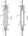
- FIG. 1 illustrates a pressure spike absorbing system 100 according to some embodiments of the present disclosure.
- the pressure spike absorbing system 100 can comprise a housing 102, an expandable reservoir 104, and a cap 106.
- the pressure spike absorbing system 100 is coupled with a first portion of a tubing 110 and second portion of a tubing 112.
- a vent passage 108 of the pressure spike absorbing system 100 permits a gas to exit and enter a cavity of the housing 102 during expansion and contraction of the expandable reservoir 104.
- the pressure within the IV set increases due to an increase in fluid volume within the IV set.
- the increased pressure can be received by the pressure spike absorbing system 100, wherein the expandable reservoir 104 can provide less resistance to the pressure than other portions of the IV set.
- the pressure causes the expandable reservoir 104 to expand and the inner volume therein to increase.
- the increased inner volume of the expandable reservoir 104 accommodates the increase in fluid volume.
- the pressure spike absorbing system 100 reduces the resistance to flow during injection of the fluid into the IV set and prevents the increase in pressure from causing damage to other portions of the IV set.
- Figure 2 illustrates a cross-sectional view of a housing 102 of the pressure spike absorbing system 100.
- the housing 102 is configured to receive at least a portion of the expandable reservoir 104 within a cavity of the housing.
- the housing 102 can limit expansion of the expandable reservoir 104, and can protect the expandable reservoir 104 from unintentional contact with a foreign object, which can damage or affect performance of the expandable reservoir 104.
- the housing 102 can include a first portion 120, a second portion 122, a cavity 126, a first retaining bore 128, and a first tubing passage 132.
- the first portion 120 and the second portion 122 can comprise opposite portions of the housing 102. In some embodiments, the first portion 120 and the second portion 122 can be positioned adjacent to each other.
- the housing 102 can be shaped as a tube or cylinder, and can have a cross-sectional profile that includes a regular or irregular shape.
- the cross-sectional profile can include any of a circle, oval, square, rectangle, triangle, or combination thereof.
- the housing 102 can be formed monolithically, as single piece, or can be formed of multiple pieces coupled together.
- the housing 102 can be configured to limit the volume of fluid received into the pressure spike absorbing system 100 by restricting expansion of the expandable reservoir 104.
- the housing 102 can have a size that corresponds to a volume of fluid to be received by the pressure spike absorbing system 100.
- a pressure spike absorbing system 100 that is intended to receive a small volume of fluid can be configured with a smaller expandable reservoir 104 compared to a pressure spike absorbing system 100 that is intended to receive a relatively larger volume of fluid.
- a pressure spike absorbing system 100 intended to receive a smaller expandable reservoir 104 can have a smaller housing 102 relative to a pressure spike absorbing system 100 intended to receive a larger expandable reservoir 104.
- An inner surface 124 of the housing can form a cavity 126 for the expandable reservoir.
- the cavity 126 can be formed within a portion of the housing 102, and is configured to extend around an outer surface of the expandable reservoir 104, or a portion thereof.
- the cavity 126 can extend from the second portion 122 of the housing toward the first portion 120 of the housing.
- the cavity 126 can extend from an end of the housing 102 at the first or second portion 120 or 122, toward the other of the first or second portion 120 or 122.
- the cavity 126 extends between the first portion 120 and the second portion 122. Further, the cavity 126 can extend through any of the first portion 120 and the second portion 122 of the housing 102.
- the cavity 126 can have a length L1 that extends between the first portion 120 and the second portion 122.
- the length L1 can be at least about 1.0 inch and/or less than or equal to about 6.0 inches. Further, the length L1 can also be between about 2.0 inches and about 4.0 inches.
- the cavity 126 can have a cross-sectional profile that is transverse to a housing axis A1 that extends between the first portion 120 and the second portion 122.
- the cross-sectional profile of the cavity 126 can includes a regular or irregular shape.
- the shape of the cross-sectional profile can include any of a circle, oval, square, rectangle, triangle, or combination thereof.
- the cross-sectional profile of the cavity 126 can have a width W1 that extends between opposing inner surfaces of the cavity.
- the width W1 can be at least about 0.25 inch and/or less than or equal to about 2.0 inches. Further, the width W1 can also be between about 0.5 inch and 1.0 inch.
- the size of the cavity 126 can be described by a volume defined by the inner surface 124 of the housing that forms the cavity 126.
- the cavity 126 can have a volume of at least about 0.25 cc and/or less than or equal to about 15 cc. Further, the capacity can also be between about 1 cc and about 6 cc.
- the differential capacity can designate the volume, which the pressure spike absorbing system 100 is intended to accommodate.
- the differential capacity can be at least about 0.25 cc and/or less than or equal to about 10 cc, or between about 0.5 cc and about 5 cc. In some embodiments of the present disclosure, the differential capacity is 3 cc.
- the volume or differential capacity of the cavity 126 can be a ratio relative to a volume of the expandable reservoir 104.
- the volume or differential capacity of the cavity can be at least about 10% and/or less than or equal to about 150% larger than the volume of the expandable reservoir 104.
- the volume or differential capacity of the cavity can be between about 25% and about 50% larger than the volume of the expandable reservoir 104.
- a first retaining bore 128 of the housing 102 is configured to receive a portion of the expandable reservoir 104.
- the first retaining bore 128 retains a portion of the expandable reservoir 104, and restricts movement of the expandable reservoir relative to the housing 102.
- the first retaining bore 128 can be formed by an inner surface of the housing 102.
- the first retaining bore 128 extends from the cavity 126 toward the first portion 120 of the housing.
- the first retaining bore 128 can extend from the cavity 126 through an outer surface of the housing 102.
- the first retaining bore 128 can have a shape, or cross-sectional profile, that corresponds with a shape of the expandable reservoir 104.
- the cross-sectional profile of the first retaining bore 128 can be the same or about the same as a cross-sectional profile of an outer surface of the expandable reservoir 104.
- the first retaining bore 128 can have a length L2 that extends between the cavity 126 and the first portion 120 of the housing 102.
- the length L2 of the retaining bore corresponds to a length of the expandable reservoir 104 that can be retained therein.
- the length L2 of the retaining bore is a ratio relative to length L3 of the expandable reservoir 104.
- the length L2 of the retaining bore 128 can be at least about 1% and/or less than or equal to about 49% of the length L3 of the expandable reservoir 104. Further, the length L2 of the retaining bore can also be between about 20% and about 30% of the length L3 of the expandable reservoir 104.
- the a portion of the expandable reservoir 104 is positioned within the first retaining bore 128.
- the expandable reservoir 104 is positioned within the first retaining bore 128 so that the outer surface of the expandable reservoir engages against the inner surface of the housing along the first retaining bore 128.
- the engagement between the expandable reservoir 104 and the first retaining bore 128 resists movement of the expandable reservoir 104 relative to the housing 102.
- the first retaining bore 128 can resists movement of the expandable reservoir 104 along the housing axis A1, and/or can resist rotational movement of the expandable reservoir 102 around the housing axis A1.
- the housing 102 can include a transition surface 130 between the cavity and the retaining bore to prevent damage to the expandable reservoir 104 during expansion of the reservoir and return of the expandable reservoir to an unrestrained orientation.
- the transition surface 130 forms a gradual transition between an inner surface of the housing at the cavity and an inner surface of the housing at the first retaining bore 128. The gradual transition of the inner surface of the housing 102 reduces the likelihood of creating a stress point on an expandable reservoir engaged against the housing 102.
- the transition surface 130 can be formed by an inner surface 124 of the housing 102 between the cavity 126 and the first retaining bore 128.
- the transition surface 130 can be shaped with a cross-sectional width that tapers between the cavity 126 and the first retaining bore 128.
- the cross-sectional width of the inner surface 124 can taper from the cavity 126 toward the first retaining bore 128.
- a cross-sectional width of the cavity 126 is greater than a cross-sectional width of the first retaining bore 128, such that the inner surface 124 tapers from the cavity 126 toward the first retaining bore 128.
- a first tubing passage 132 of the housing 102 can permit a portion of tubing to extend into the housing 102.
- the first tubing passage 132 provides a passage through the housing to permit an IV tubing to be moved through the housing and coupled with any of the housing 102 and the expandable reservoir 104.
- the first tubing passage 132 extends between the cavity 126 and an outer surface of the housing 102.
- the first tubing passage 132 can extend from the first retaining bore 128 toward the first portion 120 of the housing.
- the first tubing passage 132 can be aligned with the first retaining bore 128 so that a passage extends through each of the first tubing passage 132 and the first retaining bore 128.
- the axis A1 extends through the first tubing passage 132 and the first retaining bore 128.
- the first tubing passage 132 is positioned between the first portion 120 and the second portion 122 of the housing, and extends from the cavity 126 to an outer surface of the housing 102.
- the first tubing passage 132 can have a cross-sectional width that permits a tubing inserted therethrough to move relative to the housing 102.
- the first tubing passage 132 includes a cross-sectional width that is about the same cross-sectional width of the tubing, thereby providing an interference fit between the tubing and the first tubing passage 132.
- the cross-sectional profile of the first tubing passage 132 is less than the cross-sectional profile of the expandable reservoir 104.
- the housing 102 comprises a ventilation passage 108.
- the ventilation passage 108 permits a gas to move into and out of the housing 102.
- a gas can be displaced from the housing 102 when the expandable reservoir 104 increases in size, or moves toward an expanded orientation.
- the ventilation passage 108 permit a gas to move into the housing 102.
- the ventilation passage 108 can be shaped as an opening that extends through the housing.
- the ventilation passage 108 can extend between an inner surface of the housing and an outer surface of the housing. In some embodiments of the present disclosure, the ventilation passage 108 extends from the cavity to an outer surface of the housing.
- a portion of the ventilation passage 108 can be positioned along a portion of the housing 102 forming the cavity 126, thereby permitting a gas to move toward or away from the housing.
- the pressure spike absorbing system 100 comprises more than one ventilation passage 108.
- a first ventilation passage 108 can be positioned proximal to the first portion 120 of the housing, and a second ventilation passage 108 can be positioned proximal to the second portion 122 of the housing.
- the ventilation passage 108 can be sized to limit the rate of gas moving between the cavity and an atmosphere adjacent the outer surface of the housing. As a result, the ventilation passage 108 can be configured to regulate the rate of expansion of the expandable reservoir 108.
- the ventilation passage 108 can be any of a passage, a bore, a channel, and a groove that extends between the cavity 126 and an atmosphere adjacent an outer surface of the pressure spike absorbing system 100.
- the ventilation passage 108 can be a passage that extends through any of the first portion 120 and the second portion 122 of the housing.
- the ventilation passage 108 can be a channel that extends along a surface of any of the cavity 126, the first retaining bore 128, and the first tubing passage 132.
- the ventilation passage 108 can be any of a passage that extends through the cap 106, and a channel that extends along a surface of the cap 106.
- the housing 102 can comprise a material that is configured to resist deformation during intended use of the pressure spike absorbing system 100.
- the material of the housing 102 may be rigid relative to the expandable reservoir 104.
- the housing 102 can be more rigid than the expandable reservoir 104 such that when the expandable reservoir 104 is urged against the housing during expansion, the housing 102 resists changing shape or size.
- the material of the housing 102 can be selected to limit or prevent expansion of the expandable reservoir 104 beyond a threshold.
- the material of the housing 102 can be any of a plastic, a metal, a glass, a rubber, a composite, and any combination thereof.
- the housing 102 can permit a change of shape.
- the material of the housing can be configured to maintain shape of the housing up to a specified pressure and then be urged or biased by the expandable reservoir.
- a portion of the housing can flex, relative to other portions of the housing, or a portion of the housing can be moveable, relative to other portions of the housing.
- the housing 102 can protect the expandable reservoir 104 from damage by preventing contact from a foreign object or person against the expandable reservoir 104. Contact by a sharp or abrasive object against the expandable reservoir 104 may tear, cut, or penetrate the expandable reservoir 104 and cause a leak in the IV set.
- the housing 102 can prevent damage to the expandable reservoir 104 by resisting undesired expansion of the expandable reservoir 104, which may cause the expandable reservoir 104 to tear.
- the housing 102 maintains a shape of the expandable reservoir 104, thereby preventing bending or kinking of the reservoir, which may affect intended performance of the system or damage to the expandable reservoir 104.
- the housing 102 is coupled with the expandable reservoir 104 and the cap 106 to form the pressure spike absorbing system 100.
- the expandable reservoir 104 is positioned within the cavity 126 of the housing, and the cap 106 is coupled to the housing 102 and the expandable reservoir 104.
- the pressure spike absorbing system 100 can be assembled with a first portion of the expandable reservoir 104, comprising the first opening, positioned in a first retaining bore 128 of the housing.
- the cap 106 can be coupled with the housing 102 so that a second portion of the expandable reservoir, comprising the second opening, is positioned in a retaining bore of the cap 106. When the pressure spike absorbing system 100 is assembled, a third portion of the expandable reservoir is positioned within the cavity 126.
- a cross-sectional view of a cap 106 of the pressure spike absorbing system 100 is illustrated.
- the cap 106 is configured to couple with the housing 102 to enclose the cavity 126 and retain a portion of the expandable reservoir 104.
- the cap 106 can be coupled with any of an expandable reservoir 104 and an IV tubing to retain the pressure spike absorbing system 100 with the IV tubing.
- a removable cap 106 can permit modular assembly of the pressure spike absorbing system 100.
- portions of the pressure spike absorbing system 100 can be interchangeably assembled together and assembled with an IV set.
- the cap 106 can be shaped as a cover or plug that couples with the housing 102 to enclose the cavity 126 and/or engage the expandable reservoir 104.
- the cap 106, or portions thereof, can extend over an outer surface and along the inner surface 124 of the housing 102.
- the cap can also be shaped as a cover that extends over an outer surface of the housing 102.
- the cap 106 can include a first end portion 202, and a second end portion 204, opposite the first end portion 202.
- the cap 106 includes a second retaining bore 208 and a second tubing passage 210 of the pressure spike absorbing system 100.
- a cap axis B1 extends between the first end portion 202 and the second end portion 204.
- the first end portion 202 includes a lip 206 that extends radially outward relative to the cap axis B1.
- a surface 214 of the lip, facing toward the second end portion 204, can engage against the second portion 122 of the housing.
- the first end portion 202 can have a cross-sectional profile that is transverse relative to the cap axis B1.
- the cross-sectional profile of the first end portion 202 can be the same as a cross-sectional profile of the housing 102 so that an outer radial surface of the lip 206 is flush or aligns with an outer radial surface of the housing 102 when the cap is coupled with the housing 102.
- the second end portion 204 of the cap can extend from the first end portion 202.
- the second end portion 204 can have a cross-sectional profile that is transverse relative to the cap axis B1.
- the cross-sectional profile of the second end portion 204 can be the same as a cross-sectional profile of the cavity 126 so that an outer radial surface of the second end portion 204 engages against the inner surface 124 of the housing when the cap is coupled with the housing 102.
- the second end portion 204 can have a width W2 that extends between opposing outer surfaces of the cap.
- the width W2 of the cap can be the same or about the same as the width W1 of the cavity.
- the cap 106 can be coupled with the housing 102 by an interference fit between an outer radial surface of the second end portion 204 of the cap and an inner surface 124 of the housing.
- the cap 106 and the housing 102 are coupled together by any of an interference fit, weld, adhesive, and mechanical coupling.
- the cap 106 can be adhered or welded with the housing 102.
- the cap 106 and the housing 102 can comprise mating threads, a corresponding pin and groove, or a mechanical coupling.
- the cap 106 can include a second retaining bore 208 configured to receive portion of the expandable reservoir 104.
- the second retaining bore 208 can be configured to provide the same function and features as the first retaining bore 128 described above. Accordingly, some details and function of the retaining bore are not repeated here for brevity.
- the second retaining bore 208 can be formed by an inner surface of the cap 106.
- the second retaining bore 208 extends from an end of the second end portion 204 toward the first end portion 202. In some embodiments of the present disclosure, the second retaining bore 208 can extend through the first end portion 202 and the second end portion 204.
- the second retaining bore 208 can function like that of the first retaining bore 128, to receive and/or retain a portion of the expandable reservoir 104. Accordingly, like the first retaining bore 128, the second retaining bore 208 can be shaped with a cross-sectional profile the is the same or about the same as a cross-sectional profile of an outer surface of the expandable reservoir 104.
- a length L4 of the second retaining bore 208 can be about the same as the length L2 of the first retaining bore 128.
- the second retaining bore 208 can have a different length or width than the first retaining bore 128.
- a cap 106 having a second retaining bore length L4 that is greater than the first retaining bore length L2 can be used to receive a longer portion of the expandable reservoir 104 relative to the first retaining bore 128.
- a cap 106 having a second retaining bore length L4 that is less than the first retaining bore length L2 can be used to receive a shorter portion of the expandable reservoir 104 relative to the first retaining bore 128.
- Using a cap having a longer or shorter second retaining bore length, relative to the retaining first retaining bore length can reduce or increase, respectively, the portion of the expandable reservoir 104 than can expand.
- the cap 106 can include a transition surface 212 to prevent damage to the expandable reservoir 104 during expansion of the reservoir and return of the expandable reservoir to an unrestrained orientation.
- the transition surface 212 of the cap can be configured to provide the same function and features as the transition surface 130 of the housing described above. Accordingly, some details and function of the transition surface 212 are not repeated here for brevity.
- the transition surface 212 can be positioned along a portion of the second retaining bore 208.
- the transition surface 212 can be shaped as a chamfer along the surface of the second retaining bore 208.
- the transition surface 212 is a concaved portion of an end surface of the cap 106
- the transition surface 212 can have a cross-sectional width that is greater than the cross-sectional width of the second retaining bore 208.
- the cross-sectional width of the transition surface 212 tapers from the second end portion 204 toward the first end portion 202 of the cap.
- the cross-sectional width of the second retaining bore 208 tapers from the second end portion 204 toward the first end portion 202 of the cap.
- the second retaining bore 208 can have a first cross-sectional width proximal to the second end portion 204 of the cap that is about equal to the cross-sectional width of the cavity 126, and a second cross-sectional width proximal to first end portion 202 that is less than the first cross-sectional width.
- the cap 106 can include a second tubing passage 210 that extends through the cap 106 to permit a portion of tubing to extend into the housing 102.
- the second tubing passage 210 can be configured to provide the same function and features as the first tubing passage 132 described above. Accordingly, some details and function of the retaining bore are not repeated here for brevity.
- the second tubing passage 210 extends between first end portion 202 and the second end portion 204 of the cap 106.
- the second tubing passage 210 can extend from the second retaining bore 208 toward the first end portion 202 of the cap 106.
- the second tubing passage 210 can be aligned with the second retaining bore 208 so that a passage extends through each of the second tubing passage 210 and the second retaining bore 208.
- the axis B1 extends through the second tubing passage 210 and the second retaining bore 208.
- the second tubing passage 210 can permit a segment of tubing to be inserted through the cap 106. For example, a portion of IV tubing can be moved through the second tubing passage 210 to couple with a portion of the expandable reservoir 104.
- the second tubing passage 210 is shaped as a notch or channel that extends through a portion of the cap 106.
- second tubing passage 210 can be a channel that extends between the first end portion 202 and the second end portion 204 of the cap 106, and from an outer radial surface toward the cap axis B1.
- the second tubing passage 210 extends through a portion of the housing 102.
- the second tubing passage 210 can be any of a passage or channel through the second portion 122 of the housing.
- the cap 106 can comprise a material that is configured to resist deformation during use of the pressure spike absorbing system 100.
- the material of the cap 106 can about the same or similar in hardness as the housing 102.
- the cap 102 comprises a material with a hardness that is less than the housing 102 to permit the cap 102 be partially deformed during coupling of the cap 106 with the housing 102, resulting in an interference fit with the housing 102.
- the second portion of the expandable reservoir comprising the second opening, extends into the second retaining bore 208.
- the first retaining bore 128 can receive a first portion of the expandable reservoir 104
- the second retaining bore 208 can receive a second portion of the expandable reservoir 104.
- the second retaining bore 208 can prevent movement of the expandable reservoir 104 relative to the housing 102 and cap 106. For example, when portions of an expandable reservoir 104 are positioned within the first retaining bore 128 and the second retaining bore 208, movement of the expandable reservoir 104 along an axis between the first and second retaining bore is limited.
- FIG. 4 a cross-sectional view of an expandable reservoir 104 of the pressure spike absorbing system 100 is illustrated.
- the expandable reservoir 104 is configured to receive a fluid, such as a liquid or gas, and to deform to expand and accommodate the increase in fluid.
- the expandable reservoir 104 can be shaped as a tube having a first opening 302, a second opening 304, and a passage 306 that is in fluid communication with the first and second opening.
- the passage 306 can extend between the first opening 302 and the second opening 304.
- the first opening 302 and the second opening 304 are in fluid communication with the passage 306, thereby permitting a fluid to move into and out of the passage 306 through any of the first and second opening.
- the expandable reservoir 104 is illustrated as having a tubular shape, the expandable reservoir and/or cavity can be any regular or irregular shape, including any of a sphere, square, rectangle, and oval.
- the expandable reservoir 104 can have a cross-sectional profile transverse to an expandable reservoir axis C1 that extends between the first portion 120 and the second portion 122.
- the cross-sectional profile can be a circle; however, the cross-sectional profile can also include any of a circle, oval, square, rectangle, triangle, and combination thereof.
- the cross-sectional profile can be consistent along the length of the expandable reservoir 104, or can change along the length of the expandable reservoir 104.
- the passage 306 of the expandable reservoir can have a cross-sectional width W3 that is about equal to a cross-sectional width of the outer surface of the IV tubing to permit a portion of the IV tubing to be moved into the passage 306.
- a cross-sectional width W3 of the passage 306 at first opening 302 and the second opening 304 can be the same as the cross-sectional width of the outer surface of the IV tubing.
- the cross-sectional width W3 of the passage is greater than the cross-sectional width of the outer surface of the IV tubing, such that a gap or space exists between the inner surface of the expandable reservoir 104 and the outer surface of the IV tubing.
- the gap can permit an adhesive or other joining material to be used to couple the IV tubing with the expandable reservoir 104.
- the any of the expandable reservoir 104 and the IV tubing can be configured to shrink or expand to permit coupling of the IV tubing with the expandable reservoir 104. For example, a portion of the IV tubing can be inserted through the first or second opening 302 and 304, and then the expandable reservoir 104, or portion having the IV tubing therein, can be reduced in size to engage the IV tubing.
- the passage 306 of the expandable reservoir can have a size that permits a volume of fluid to be received therein.
- the size of the expandable reservoir can be configured to receive a volume when in the unrestrained orientation and/or in the expanded orientation.
- the volume can be at least about 0.25 cc and/or less than or equal to about 10 cc, or between about 0.5 cc and about 5 cc.
- the passage 306 can have a volume that is 3 cc.
- the expandable reservoir 104 comprises a material that is configured to resiliently deform toward an expanded orientation and return to an unrestrained orientation.
- the material of the expandable reservoir 104 can have a durometer that permits a specified rate of expansion and/or return of the expandable reservoir 104 to an unrestrained orientation.
- the material can be configured with a durometer hardness so that when the expandable reservoir 104 is in an expanded orientation, the fluid therein is directed out of the pressure spike absorbing system 100 at a specified rate.
- the expandable reservoir 104 can have a first and second opening; however, in some embodiments, the expandable reservoir 104 can have one opening in fluid communication with a passage or cavity.
- An expandable reservoir having one opening can permit a fluid to enter the passage and cause the expandable reservoir to expand to accommodate an increase in pressure of the IV set. When the force of the expandable reservoir overcomes the fluid pressure therein, the expandable reservoir will return toward the unrestrained orientation and cause the fluid to be directed out of the opening.
- An upstream flow control valve positioned between a fluid access port and the expandable reservoir, can prevent backflow of the fluid toward the access port.
- the expandable reservoir 104 includes any of a bellows and/or folds.
- the expandable reservoir 104 can have one or more fold the extends between the first and second opening, along the expandable reservoir axis C1.
- one or more fold that extends along the circumference of the passage 306, around the expandable reservoir axis C1. The one or more fold can unfold or expand when pressure is applied to the passage 306 to increase the volume within the expandable reservoir.
- the expandable reservoir 104 includes a ridge that can resist further movement of the expandable reservoir 104 relative to the housing 102 and/or IV tubing.
- the ridge can extend away from the outer surface of the expandable reservoir axis C1 to engage against the housing 102.
- a ridge can extend from an inner surface of the expandable reservoir 102 to engage against an IV tubing inserted therein.
- the expandable reservoir 104 includes an alignment feature 310.
- the alignment feature 310 can be any of a dimple, indentation, channel, groove, and ridge that permit a portion of the expandable reservoir 104 to change shape and/or direction.
- the expandable reservoir 104 can have a groove the extends into the outer surface and around the expandable reservoir axis C1 proximate to each of the first and second opening 302 and 304. When pressure is directed to the passage 306, the portion of the expandable reservoir 104 between the grooves can more readily expand radially outward, relative to the portion of the of the expandable reservoir 104 between the groove and the first and second opening 302 and 304.
- the alignment feature 310 can be a marking on an inner and/or outer surface of the expandable reservoir 104 to permit observation of the position of the expandable reservoir 104 relative to the housing 102.
- the expandable reservoir 104 can include a restraining mechanism that resists radial expansion.
- the restraining mechanism can be a wire can extend along the expandable reservoir between the first opening 302 and the second opening 304.
- the restraining mechanism can be a material having a lattice or mesh shape that extends along the outer surface of the expandable reservoir 104.
- the restraining mechanism can be a tubular structure that extends along the outer surface of the expandable reservoir 104.
- the pressure spike absorbing system 100 includes a spring or lever that can resist radial expansion of the expandable reservoir 104.
- a spring or lever can extend from the inner surface 124 of the housing toward the expandable reservoir 104.
- an outer surface of the expandable reservoir 104 can engage against the spring or lever. The force of the spring or lever against the expandable reservoir 104 could direct the expandable reservoir 104 radially inward, thereby causing the fluid to be directed out of the passage 306.
- FIG. 5 an exploded view of the pressure spike absorbing system 100 is illustrated. It should be understood that the following description illustrates assembly and cooperation between portions of the pressure spike absorbing system 100. Accordingly, assembly of the pressure spike absorbing system 100 can include any of the following description, in any variation or sequence.
- the pressure spike absorbing system 100 can be coupled with an existing section of IV tubing or fluid delivery system.
- the tubing can be cut to form a first portion of tubing 110 and a second portion of tubing 112. An end of the first and second portion of tubing 110 and 112 can then be coupled to the pressure spike absorbing system 100.
- the pressure spike absorbing system 100 can be coupled with IV tubing, for example, as a portion of an IV set or fluid delivery system.
- the tubing 110 is inserted through the housing 102.
- the tubing 110 can be inserted through the housing 102 from the first portion 120 toward the second portion 122 of the housing.
- an end portion of the tubing 110 is moved through the tubing passage 132, the first retaining bore 128, and the cavity 126.
- the tubing 110 can be coupled to the expandable reservoir 104.
- the tubing 110 can be coupled to the expandable reservoir 104 by inserting the end portion of the tubing 110 through the first opening 302 of the expandable reservoir.
- the tubing 110 can be moved through the first opening 302 and into the passage 306 so that the outer surface of the tubing 110 extends along the inner surface of the expandable reservoir 104.
- a portion of the tubing 110 within the passage 306 is identified in broken line in Figure 5 .
- the end portion of the tubing 110 extends a distance D1 from the first opening 302 of the expandable reservoir.
- tubing 112 is inserted through the cap 106.
- the tubing 112 is inserted through the cap 106 by moving the end portion of the tubing 112 through the tubing passage 210 and second retaining bore 208, from the first end portion 202 toward the second end portion 204.
- the tubing 112 can be coupled to the expandable reservoir 104.
- the tubing 112 can be coupled to the expandable reservoir 104 by inserting the end portion of the tubing 112 through the second opening 304 of the expandable reservoir.
- the tubing 112 can be moved through the second opening 304 and into the passage 306 so that the outer surface of the tubing 112 extends along the inner surface of the expandable reservoir 104.
- the portion of tubing 112 can be extended a distance D1 into the passage 306.
- the cap 106 can be moved toward the expandable reservoir 104 so that a portion of the expandable reservoir, adjacent to the second opening 304, is positioned within the second retaining bore 208 and the second opening 304 of the expandable reservoir is aligned with the second tubing passage 210.
- the expandable reservoir 104 and a portion of the cap 106 can be moved into the cavity 126 of the housing so that a portion of the expandable reservoir adjacent to the first opening 302 is positioned within the first retaining bore 128 and the first opening 302 is aligned with the first tubing passage 132.
- the expandable reservoir 104 extends between the first retaining bore 128 and the second retaining bore 208.
- the expandable reservoir 104 can first be inserted into the housing 102, and then the cap 106 coupled with the housing. When the cap 106 is coupled with the housing 102, the second end portion 204 of the cap is inserted into the housing 102, a portion of the expandable reservoir 104 is received into the second retaining bore 208.
- Figure 6A illustrates an expandable reservoir 104 in an unrestrained orientation
- Figure 6B illustrates an expandable reservoir 104 in an expanded orientation.
- a portion of the expandable reservoir 104, adjacent to the first opening 302 is positioned within the first retaining bore 128, and the first opening 302 is aligned with the first tubing passage 132.
- a portion of the tubing 110 extends through the first tubing passage 132 and is coupled with the first opening 302 of the expandable reservoir.
- the another portion of the expandable reservoir is coupled with the cap 106 so that the second opening 304 is aligned with the second tubing passage 210.
- a portion of the tubing 112 extends through the second tubing passage 210 and is coupled with the second opening 304 of the expandable reservoir.
- the outer surface of the expandable reservoir 104 and the inner surface 124 of the housing are spaced apart or separated to permit the expandable reservoir 104 to move, i.e., expand, toward the inner surface of the housing.
- the space between the outer surface of the expandable reservoir 104 and the inner surface 124 of the housing define a capacity of the pressure spike absorbing system 100.
- the vents 108 of the housing permit a gas to be directed out of the housing 102 when the expandable reservoir 104 expands, and a gas to be drawn into the housing 102 when the expandable reservoir 104 moves toward the unrestrained orientation.
- the expandable reservoir 104 When coupled with the tubing of an IV set, or other fluid delivery system, the expandable reservoir 104 can deform to relieve pressure and resistance from other portions of the IV set or system. For example, when a fluid is injected into the IV set, the fluid is not immediately injected into the patient; thus, pressure is increased within the IV set. The increase in fluid pressure can act upon portions of the IV set having the least resistance. In some instances, the increase in pressure causes the IV set to become damaged and leak, and can cause resistance to the force injecting the fluid into the IV set.
- the expandable reservoir can provide less resistance, relative to other portions of the IV set, the expandable reservoir deforms or moves to an expanded orientation to relieve the pressure, as illustrated in Figure 6B .
- the expandable reservoir deforms the volume of the passage 306 increases and permits the fluid to be accommodated therein.
- pressure is relieved or redirected from the other portions of the IV set, which may otherwise become damaged.
- deformation of the expandable reservoir 104 permits the fluid to be injected into the IV set with less resistance.
- a force of the expandable reservoir 104 is directed against the fluid within the passage 306; the force urges the expandable reservoir 104 toward the unrestrained orientation.
- a force of the expandable reservoir 104 can be directed toward the expandable reservoir axis C1.
- the expandable reservoir 104 can move toward the unrestrained orientation.
- the volume of the passage 306 becomes smaller, thereby directing the fluid out of the expandable reservoir 104.
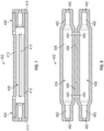
- the pressure spike absorbing system 100 can include any of the features, or any combination of features, described in the present disclosure. Referring to Figures 7 and 8 , embodiments of a housing having features described in the present disclosure are illustrated.
- Figure 7 illustrates a cross-sectional view of a housing 402 having a first portion 404 and a second portion 406, and a cavity 408 that extends through the first and second portions.
- Each of the first portion 404 and the second portion 406 include a cap 410 coupled thereto.
- the cavity 408 can reduce manufacturing complexity by limiting variations in shape and/or cross-sectional of the passage through the housing 402. Further, the housing 402 can permit a broader manufacturing tolerance, because critical sizing tolerances can be limited to the cap 410.
- the housing 402 can include an opening 412 that extends between the inner and outer surface of the housing 402.
- the opening 412 can be an elongated passage that extends between the first portion 404 and the second portion 406.
- a portion of the housing 402, between the first portion 404 and the second portion 406, includes a mesh or lattice structure comprising a plurality of openings.
- the opening 412 can permit ventilation of the cavity 408.
- the opening 412 permits observation of the cavity and/or the expandable reservoir.
- the opening 412 can permit observation and a determination of whether the expandable reservoir is in a unrestrained or expanded orientation.
- the opening 412 can function like a window and can include a transparent pane to resist movement of an object through the opening 412, yet can permit observation into the housing.
- any portion, or the entirety of the pressure spike absorbing system can be formed with a transparent material to permit observation into the cavity.
- the pressure spike absorbing system is modular or modifiable. Because any of the housing, the cap of the first portion 404, and the cap of the second portion 406, may be interchangeable or modular, the pressure spike absorbing system can be configured for use with different pressure and/or volume capacities, and/or for use with a variety of expandable reservoirs and IV tubing.
- the cap of the first portion 404 can be selected to permit a first IV tubing having a first cross-sectional diameter to be moved therethrough.
- a cap of the second portion 406 can be selected to permit a second IV tubing having a second cross-sectional diameter, different than the first cross-sectional diameter, to be moved therethrough.
- the pressure spike absorbing system can be used to transition a portion of the IV set from an IV tubing having a first cross-sectional diameter to an IV tubing having a second cross-sectional diameter.
- Figure 8 illustrates a housing 452 having more than one portion, which can be coupled together.
- the housing 452 can have a first portion 454 and a second portion 456, which can be coupled together to form any of a cavity, a retaining bore, a tubing passage, and vent passage.
- any of the first portion 454 and the second portion 456 form a portion of a cavity 458, a portion of a retaining bore 460, a portion of a tubing passage 462, and a portion of a vent passage 464.
- the first portion 454 and the second portion 456 of the housing can be coupled together using any fastening or joining method or mechanism.
- the first and second portions can include a complimentary pin and pocket, or snap and pawl.
- the first and second portions can be joined together with an adhesive or welding.
- a retainer such as a band, can extend over or around an outer surface of the first portion 454 and the second portion 456 of the housing.
- the first portion 454 and the second portion 456 of the housing can be coupled together by a living hinge 466, which permits movement of the first portion 454 relative to the second portion 456.
- the pressure spike absorbing system having a housing 452 with a first portion 454 and a second portion 456 can be assembled by first coupling an expandable reservoir between portions of IV tubing.
- the expandable reservoir can then be positioned within a portion of the cavity 458 with a first portion of the expandable reservoir positioned in a portion of a retaining bore 460 so that a first portion of the tubing extends through a first tubing passage 462.
- a second portion of the expandable reservoir is positioned in a portion of another retaining bore 460 so that second portion of the tubing extends through another tubing passage 462.
- the first and second portions of the housing can then be coupled together to enclose the expandable reservoir within the cavity 458.
- the first and second portions of the housing can be coupled together by moving, or rotating, the first portion 454 of the housing toward the second portion 456 of the housing.
- the pressure spike absorbing system can include a flow control valve to resist movement of a fluid relative to the pressure spike absorbing system.
- the flow control valve can permit fluid to move from an access port of the IV set toward the pressure spike absorbing system, and prevent the fluid from moving from the pressure spike absorbing system toward the access port.
- the flow control valve can resist movement of a fluid toward the access port when the expandable reservoir moves from an expanded orientation toward an unrestrained orientation. By resisting movement of fluid toward the access port, the fluid is directed toward the patient.
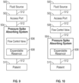
- the fluid delivery systems can include a fluid source 500, such as a medicament bag, an access port 502, and a pressure spike absorbing system 504.
- the fluid source 500, access port 502, and pressure spike absorbing system 504 can be fluidly coupled together and to a patient 510 by tubing 512.
- a pressure spike absorbing system 504 can include a flow control valve 506 and an expandable reservoir 508.
- the flow control valve 506 can be incorporate into any of the housing and the expandable reservoir of the pressure spike absorbing system 504.
- the flow control valve can be fluidly coupled with the tubing passage and/or the retaining bore at a first portion of the housing.
- the flow control valve 506 can be coupled to the fluid delivery system, between the access port 502 and the pressure spike absorbing system 504.
- the flow control valve 506 can be fluidly coupled to the tubing 512 between the access port 502 and the pressure spike absorbing system 504.
- the fluid moves through the flow control valve 506 and into the pressure spike absorbing system 504.
- the expandable reservoir 508 moves toward the unrestrained orientation, the flow control valve 506 resists movement of the fluid in a direction from the pressure spike absorbing system 504 toward the access port 502.
- the fluid moves toward the patient 510.
Landscapes
- Health & Medical Sciences (AREA)
- Engineering & Computer Science (AREA)
- General Engineering & Computer Science (AREA)
- Biomedical Technology (AREA)
- Public Health (AREA)
- Heart & Thoracic Surgery (AREA)
- Hematology (AREA)
- Life Sciences & Earth Sciences (AREA)
- Animal Behavior & Ethology (AREA)
- General Health & Medical Sciences (AREA)
- Anesthesiology (AREA)
- Veterinary Medicine (AREA)
- Vascular Medicine (AREA)
- Mechanical Engineering (AREA)
- Infusion, Injection, And Reservoir Apparatuses (AREA)
- Pipe Accessories (AREA)
- Absorbent Articles And Supports Therefor (AREA)
Claims (13)
- Durchfluss-Druckspitzen-Absorptionssystem (100) für intravenöse (IV) Therapieschläuche (110, 112), umfassend:ein Gehäuse (102) umfassend einen Hohlraum (126), einen Belüftungsdurchgang (108), der sich von dem Hohlraum (126) zu einer äußeren Oberfläche des Gehäuses (102) erstreckt, eine erste Haltebohrung (128), einen ersten Schlauchdurchgang (132), eine zweite Haltebohrung (208) und einen zweiten Schlauchdurchgang (2 10), wobei sich die erste Haltebohrung (128) von dem Hohlraum (126) zu einem ersten Abschnitt (120) des Gehäuses (102) erstreckt und der erste Schlauchdurchgang (132) sich durch den ersten Abschnitt des Gehäuses (102) von der ersten Haltebohrung (128) zu der Außenfläche des Gehäuses (102) erstreckt Gehäuses (102) erstreckt, und wobei sich die zweite Haltebohrung (208) von dem Hohlraum (126) zu einem zweiten Abschnitt des Gehäuses (122) erstreckt und der zweite Schlauchdurchgang (210) sich durch den zweiten Abschnitt des Gehäuses (122) von der zweiten Haltebohrung zu der Außenfläche des Gehäuses (102) erstreckt;ein ausdehnbares Reservoir (104), das einen ersten Abschnitt mit einer ersten Öffnung (302), einen zweiten Abschnitt mit einer zweiten Öffnung (304) und eine Innenfläche umfasst, die einen Durchgang (306) bildet, der sich zwischen der ersten und der zweiten Öffnung (302, 304) erstreckt, wobei das ausdehnbare Reservoir (104) in dem Hohlraum (126) positioniert ist mit dem ersten Abschnitt des ausdehnbaren Reservoirs (104) in der ersten Haltebohrung (128), so dass ein erster Schlauch (110) in die erste Öffnung (302) eingeführt werden kann, um mit dem ausdehnbaren Reservoir verbunden zu werden, und wobei der zweite Abschnitt des ausdehnbaren Reservoirs (104) in der zweiten Haltebohrung (128) angeordnet ist, so dass ein zweiter Schlauch (112) in die zweite Öffnung (304) eingeführt werden kann, um mit dem ausdehnbaren Reservoir verbunden zu werden;wobei, wenn ein Fluid durch den ersten Schlauch (110) injiziert wird, das Fluid in den Durchgang (306) geleitet wird, um das ausdehnbare Reservoir (104) aus einer ungehinderten Ausrichtung in eine ausgedehnte Ausrichtung zu bewegen, und wobei der Belüftungsdurchgang (108) so konfiguriert ist, dass ein Gas aus dem Hohlraum (126) herausbewegt wird, wenn sich das ausdehnbare Reservoir (104) von der ungehinderten Ausrichtung in Richtung der ausgedehnten Ausrichtung bewegt, und ein Gas in den Hohlraum (126) hineinbewegt wird, wenn sich das ausdehnbare Reservoir (104) von der ausgedehnten Ausrichtung in Richtung der ungehinderten Ausrichtung bewegt.
- Das Durchfluss-Druckspitzen-Absorptionssystem (100) nach Anspruch 1, wobei sich der Hohlraum (126) durch den zweiten Abschnitt (122) des Gehäuses (102) in Richtung des ersten Abschnitts (120) des Gehäuses (102) erstreckt.
- Das Durchfluss-Druckspitzen-Absorptionssystem (100) nach Anspruch 1, wobei eine Innenfläche des Gehäuses (102) eine Querschnittsbreite aufweist, die sich vom Hohlraum (126) zum ersten Schlauchdurchgang (132) hin verjüngt.
- Das Durchfluss-Druckspitzen-Absorptionssystem (100) nach Anspruch 1, umfassend ein Durchflussregelventil (506), das mit dem ausdehnbaren Reservoir (104) fluidisch gekoppelt ist.
- Das Durchfluss-Druckspitzen-Absorptionssystem (100) nach Anspruch 1, wobei eine Außenfläche des ausdehnbaren Reservoirs (104) in der ungehinderten Ausrichtung von einer Innenfläche des Gehäuses (102) beabstandet ist.
- Das Durchfluss-Druckspitzen-Absorptionssystem (100) nach Anspruch 1, wobei eine Außenfläche des ausdehnbaren Reservoirs (104) in der ausgedehnten Ausrichtung an einer Innenfläche des Gehäuses (102) anliegt.
- Das Durchfluss-Druckspitzen-Absorptionssystem (100) nach Anspruch 1, wobei das Fluid von dem Durchgang (306) zu dem zweiten Schlauch (112) geleitet wird, wenn sich das dehnbare Reservoir (104) von der gedehnten Ausrichtung in die ungedehnte Ausrichtung bewegt.
- Das Durchfluss-Druckspitzen-Absorptionssystem (100) nach Anspruch 1, wobei in der ungehinderten Ausrichtung und der erweiterten Ausrichtung ein Abschnitt des erweiterbaren Reservoirs (104) zwischen dem ersten und dem zweiten Abschnitt innerhalb des Hohlraums (126) positioniert ist.
- Das Durchfluss-Druckspitzen-Absorptionssystem (100) nach Anspruch 1, das eine Kappe (106) mit einem ersten Endabschnitt (202) und einem zweiten Endabschnitt (204) umfasst, wobei sich die zweite Rückhaltebohrung (208) und der zweite Schlauchdurchgang (210) durch die Kappe (106) erstrecken.
- Das Durchfluss-Druckspitzen-Absorptionssystem (100) nach Anspruch 1, wobei der Durchgang (306) des ausdehnbaren Reservoirs (104) ein erstes Volumen in der nicht eingeschränkten Ausrichtung und ein zweites Volumen, das größer als das erste Volumen ist, in der ausgedehnten Ausrichtung umfasst.
- Das Durchfluss-Druckspitzen-Absorptionssystem (100) nach Anspruch 4, wobei das Durchflussregelventil (506) zwischen dem ersten Schlauch (110) und dem ausdehnbaren Reservoir (104) gekoppelt ist, so dass das Durchflussregelventil einer Bewegung eines Fluids von dem ausdehnbaren Reservoir (104) zu dem ersten Schlauch (110) hin widersteht.
- Das Durchfluss-Druckspitzen-Absorptionssystem (100) nach Anspruch 9, wobei eine Innenfläche der Kappe (106) eine Querschnittsbreite aufweist, die sich von dem Hohlraum (126) zu dem zweiten Schlauchdurchgang (210) hin verjüngt.
- Das Durchfluss-Druckspitzen-Absorptionssystem (100) nach Anspruch 9, wobei der zweite Endabschnitt (204) in dem Hohlraum (126) des Gehäuses (102) positioniert ist.
Priority Applications (1)
| Application Number | Priority Date | Filing Date | Title |
|---|---|---|---|
| EP24214717.1A EP4487885A3 (de) | 2017-11-08 | 2018-11-07 | Druckspitzenabsorbierende systeme |
Applications Claiming Priority (2)
| Application Number | Priority Date | Filing Date | Title |
|---|---|---|---|
| US15/807,475 US11400211B2 (en) | 2017-11-08 | 2017-11-08 | Pressure spike absorbing systems |
| PCT/US2018/059649 WO2019094484A1 (en) | 2017-11-08 | 2018-11-07 | Pressure spike absorbing systems |
Related Child Applications (2)
| Application Number | Title | Priority Date | Filing Date |
|---|---|---|---|
| EP24214717.1A Division-Into EP4487885A3 (de) | 2017-11-08 | 2018-11-07 | Druckspitzenabsorbierende systeme |
| EP24214717.1A Division EP4487885A3 (de) | 2017-11-08 | 2018-11-07 | Druckspitzenabsorbierende systeme |
Publications (3)
| Publication Number | Publication Date |
|---|---|
| EP3707422A1 EP3707422A1 (de) | 2020-09-16 |
| EP3707422B1 true EP3707422B1 (de) | 2025-02-26 |
| EP3707422C0 EP3707422C0 (de) | 2025-02-26 |
Family
ID=64427249
Family Applications (2)
| Application Number | Title | Priority Date | Filing Date |
|---|---|---|---|
| EP18807527.9A Active EP3707422B1 (de) | 2017-11-08 | 2018-11-07 | Druckspitzenabsorber |
| EP24214717.1A Pending EP4487885A3 (de) | 2017-11-08 | 2018-11-07 | Druckspitzenabsorbierende systeme |
Family Applications After (1)
| Application Number | Title | Priority Date | Filing Date |
|---|---|---|---|
| EP24214717.1A Pending EP4487885A3 (de) | 2017-11-08 | 2018-11-07 | Druckspitzenabsorbierende systeme |
Country Status (6)
| Country | Link |
|---|---|
| US (2) | US11400211B2 (de) |
| EP (2) | EP3707422B1 (de) |
| JP (3) | JP7339247B2 (de) |
| CN (2) | CN111448418B (de) |
| AU (1) | AU2018366032B2 (de) |
| WO (1) | WO2019094484A1 (de) |
Families Citing this family (4)
| Publication number | Priority date | Publication date | Assignee | Title |
|---|---|---|---|---|
| CN110319303B (zh) * | 2019-07-15 | 2022-04-26 | 郑州工程技术学院 | 可降低水压频繁波动冲击力的复合压力管 |
| JP7585100B2 (ja) | 2021-03-10 | 2024-11-18 | テルモ株式会社 | 圧力緩和部材、コネクタ及び輸液チューブセット |
| CN115218056B (zh) * | 2022-08-05 | 2024-04-26 | 德帕姆(杭州)泵业科技有限公司 | 囊式脉动阻尼器 |
| US20240207094A1 (en) * | 2022-12-27 | 2024-06-27 | Johnson & Johnson Surgical Vision, Inc. | Irrigation damping in phacoemulsification |
Citations (1)
| Publication number | Priority date | Publication date | Assignee | Title |
|---|---|---|---|---|
| US4514295A (en) * | 1981-08-05 | 1985-04-30 | Fresenius Ag | Dialysis apparatus |
Family Cites Families (15)
| Publication number | Priority date | Publication date | Assignee | Title |
|---|---|---|---|---|
| US2838073A (en) * | 1953-09-01 | 1958-06-10 | Mattia Samuel P Di | Surge pressure absorber |
| US3095120A (en) | 1959-11-12 | 1963-06-25 | Swift & Co | Pumping system for meat emulsions |
| US5137175A (en) * | 1990-02-28 | 1992-08-11 | Gmi Engineering & Management Institute | Fluid storing and dispensing |
| CA2145869C (en) | 1994-04-11 | 2004-09-21 | Kodai Kinoshita | Portable analgesic system |
| ATE242020T1 (de) | 1996-03-14 | 2003-06-15 | Oneil Christine | Von patienten kontrollierbare durchflussregulierung für ein medikamentenabgabesystem |
| KR100262930B1 (ko) | 1997-06-19 | 2000-08-01 | 이영규 | 의약품주입기 |
| US6764461B2 (en) * | 1997-12-01 | 2004-07-20 | Scimed Life Systems, Inc. | Catheter system for the delivery of a low volume bolus |
| JPWO2008007422A1 (ja) | 2006-07-11 | 2009-12-10 | 株式会社塚田メディカル・リサーチ | 薬液持続注入装置 |
| US8257337B2 (en) * | 2007-05-02 | 2012-09-04 | Carefusion 303, Inc. | Intravenous fluid container |
| US8512284B2 (en) * | 2009-01-28 | 2013-08-20 | Woo Young Medical Co., Ltd. | Medical fluid dispenser |
| US8915073B1 (en) * | 2010-09-13 | 2014-12-23 | Daniel Theobald | Fluid power device, method and system |
| US8545442B2 (en) * | 2011-05-06 | 2013-10-01 | Merit Medical Systems, Inc. | Mechanically assisted inflation device handle |
| US10022497B2 (en) * | 2012-08-28 | 2018-07-17 | Osprey Medical, Inc. | Reservoir for collection and reuse of diverted medium |
| JP6707077B2 (ja) | 2014-09-11 | 2020-06-10 | オスプレイ メディカル インコーポレイテッド | アジャスタブル媒体ダイバータ |
| US10271841B2 (en) * | 2015-06-26 | 2019-04-30 | Ethicon Llc | Bailout assembly for surgical stapler |
-
2017
- 2017-11-08 US US15/807,475 patent/US11400211B2/en active Active
-
2018
- 2018-11-07 EP EP18807527.9A patent/EP3707422B1/de active Active
- 2018-11-07 JP JP2020524853A patent/JP7339247B2/ja active Active
- 2018-11-07 AU AU2018366032A patent/AU2018366032B2/en active Active
- 2018-11-07 CN CN201880072113.9A patent/CN111448418B/zh active Active
- 2018-11-07 WO PCT/US2018/059649 patent/WO2019094484A1/en not_active Ceased
- 2018-11-07 CN CN202210474276.8A patent/CN114673858B/zh active Active
- 2018-11-07 EP EP24214717.1A patent/EP4487885A3/de active Pending
-
2022
- 2022-05-12 US US17/743,357 patent/US11975174B2/en active Active
-
2023
- 2023-08-24 JP JP2023136245A patent/JP7618749B2/ja active Active
-
2025
- 2025-01-08 JP JP2025003061A patent/JP7783443B2/ja active Active
Patent Citations (1)
| Publication number | Priority date | Publication date | Assignee | Title |
|---|---|---|---|---|
| US4514295A (en) * | 1981-08-05 | 1985-04-30 | Fresenius Ag | Dialysis apparatus |
Also Published As
| Publication number | Publication date |
|---|---|
| EP3707422A1 (de) | 2020-09-16 |
| CN114673858B (zh) | 2024-06-18 |
| US20220273870A1 (en) | 2022-09-01 |
| WO2019094484A1 (en) | 2019-05-16 |
| JP2021502161A (ja) | 2021-01-28 |
| JP2023158007A (ja) | 2023-10-26 |
| CN111448418A (zh) | 2020-07-24 |
| JP7783443B2 (ja) | 2025-12-09 |
| US11400211B2 (en) | 2022-08-02 |
| JP2025039738A (ja) | 2025-03-21 |
| US20190134304A1 (en) | 2019-05-09 |
| EP3707422C0 (de) | 2025-02-26 |
| AU2018366032B2 (en) | 2024-02-08 |
| CA3081427A1 (en) | 2019-05-16 |
| JP7339247B2 (ja) | 2023-09-05 |
| CN111448418B (zh) | 2022-05-10 |
| JP7618749B2 (ja) | 2025-01-21 |
| EP4487885A3 (de) | 2025-03-26 |
| EP4487885A2 (de) | 2025-01-08 |
| US11975174B2 (en) | 2024-05-07 |
| CN114673858A (zh) | 2022-06-28 |
| AU2018366032A1 (en) | 2020-05-07 |
Similar Documents
| Publication | Publication Date | Title |
|---|---|---|
| US11975174B2 (en) | Pressure spike absorbing systems | |
| EP0947212B1 (de) | Selbstfüllender, nadelfreier Y-Adapter | |
| US8142403B2 (en) | Syringe assembly with plunger having a secondary dispensing reservoir | |
| JP7308997B2 (ja) | 注射器デバイス | |
| US5242423A (en) | Needleless syringe | |
| JP4794463B2 (ja) | 正圧排出用フラッシュ注射器 | |
| US20160361490A1 (en) | Safety needle assemblies and related methods | |
| EP3049146B1 (de) | Nadelloser verbinder | |
| EP1398053A1 (de) | Medizinischer Adapter mit spitzer Kanüle | |
| CN108348732A (zh) | 带有阀的导管装置及相关方法 | |
| WO2016068797A1 (en) | Intravenous catheter assembly | |
| US11324919B2 (en) | Blood control septum and related systems | |
| US8540682B2 (en) | Plunger activated capping system | |
| CN107635618A (zh) | 带有流量控制阀机构的导管组件和相关方法 | |
| EP3213793A1 (de) | Automatisches anti-freeflow-schutzventil für medizinische pumpen | |
| CA3081427C (en) | Pressure spike absorbing systems | |
| WO2022214490A1 (en) | Vent device, port assembly and vascular access assembly | |
| AU731365B2 (en) | Medical adapter |
Legal Events
| Date | Code | Title | Description |
|---|---|---|---|
| STAA | Information on the status of an ep patent application or granted ep patent |
Free format text: STATUS: UNKNOWN |
|
| STAA | Information on the status of an ep patent application or granted ep patent |
Free format text: STATUS: THE INTERNATIONAL PUBLICATION HAS BEEN MADE |
|
| PUAI | Public reference made under article 153(3) epc to a published international application that has entered the european phase |
Free format text: ORIGINAL CODE: 0009012 |
|
| STAA | Information on the status of an ep patent application or granted ep patent |
Free format text: STATUS: REQUEST FOR EXAMINATION WAS MADE |
|
| 17P | Request for examination filed |
Effective date: 20200514 |
|
| AK | Designated contracting states |
Kind code of ref document: A1 Designated state(s): AL AT BE BG CH CY CZ DE DK EE ES FI FR GB GR HR HU IE IS IT LI LT LU LV MC MK MT NL NO PL PT RO RS SE SI SK SM TR |
|
| AX | Request for extension of the european patent |
Extension state: BA ME |
|
| DAV | Request for validation of the european patent (deleted) | ||
| DAX | Request for extension of the european patent (deleted) | ||
| STAA | Information on the status of an ep patent application or granted ep patent |
Free format text: STATUS: EXAMINATION IS IN PROGRESS |
|
| 17Q | First examination report despatched |
Effective date: 20210521 |
|
| GRAP | Despatch of communication of intention to grant a patent |
Free format text: ORIGINAL CODE: EPIDOSNIGR1 |
|
| STAA | Information on the status of an ep patent application or granted ep patent |
Free format text: STATUS: GRANT OF PATENT IS INTENDED |
|
| INTG | Intention to grant announced |
Effective date: 20241008 |
|
| RIN1 | Information on inventor provided before grant (corrected) |
Inventor name: FEITH, RAYMOND |
|
| GRAS | Grant fee paid |
Free format text: ORIGINAL CODE: EPIDOSNIGR3 |
|
| GRAA | (expected) grant |
Free format text: ORIGINAL CODE: 0009210 |
|
| STAA | Information on the status of an ep patent application or granted ep patent |
Free format text: STATUS: THE PATENT HAS BEEN GRANTED |
|
| AK | Designated contracting states |
Kind code of ref document: B1 Designated state(s): AL AT BE BG CH CY CZ DE DK EE ES FI FR GB GR HR HU IE IS IT LI LT LU LV MC MK MT NL NO PL PT RO RS SE SI SK SM TR |
|
| REG | Reference to a national code |
Ref country code: GB Ref legal event code: FG4D |
|
| REG | Reference to a national code |
Ref country code: CH Ref legal event code: EP |
|
| REG | Reference to a national code |
Ref country code: DE Ref legal event code: R096 Ref document number: 602018079635 Country of ref document: DE |
|
| REG | Reference to a national code |
Ref country code: IE Ref legal event code: FG4D |
|
| U01 | Request for unitary effect filed |
Effective date: 20250319 |
|
| U07 | Unitary effect registered |
Designated state(s): AT BE BG DE DK EE FI FR IT LT LU LV MT NL PT RO SE SI Effective date: 20250402 |
|
| PG25 | Lapsed in a contracting state [announced via postgrant information from national office to epo] |
Ref country code: RS Free format text: LAPSE BECAUSE OF FAILURE TO SUBMIT A TRANSLATION OF THE DESCRIPTION OR TO PAY THE FEE WITHIN THE PRESCRIBED TIME-LIMIT Effective date: 20250526 |
|
| PG25 | Lapsed in a contracting state [announced via postgrant information from national office to epo] |
Ref country code: PL Free format text: LAPSE BECAUSE OF FAILURE TO SUBMIT A TRANSLATION OF THE DESCRIPTION OR TO PAY THE FEE WITHIN THE PRESCRIBED TIME-LIMIT Effective date: 20250226 |
|
| PG25 | Lapsed in a contracting state [announced via postgrant information from national office to epo] |
Ref country code: ES Free format text: LAPSE BECAUSE OF FAILURE TO SUBMIT A TRANSLATION OF THE DESCRIPTION OR TO PAY THE FEE WITHIN THE PRESCRIBED TIME-LIMIT Effective date: 20250226 |
|
| PG25 | Lapsed in a contracting state [announced via postgrant information from national office to epo] |
Ref country code: IS Free format text: LAPSE BECAUSE OF FAILURE TO SUBMIT A TRANSLATION OF THE DESCRIPTION OR TO PAY THE FEE WITHIN THE PRESCRIBED TIME-LIMIT Effective date: 20250626 Ref country code: NO Free format text: LAPSE BECAUSE OF FAILURE TO SUBMIT A TRANSLATION OF THE DESCRIPTION OR TO PAY THE FEE WITHIN THE PRESCRIBED TIME-LIMIT Effective date: 20250526 |
|
| PG25 | Lapsed in a contracting state [announced via postgrant information from national office to epo] |
Ref country code: HR Free format text: LAPSE BECAUSE OF FAILURE TO SUBMIT A TRANSLATION OF THE DESCRIPTION OR TO PAY THE FEE WITHIN THE PRESCRIBED TIME-LIMIT Effective date: 20250226 |
|
| PG25 | Lapsed in a contracting state [announced via postgrant information from national office to epo] |
Ref country code: GR Free format text: LAPSE BECAUSE OF FAILURE TO SUBMIT A TRANSLATION OF THE DESCRIPTION OR TO PAY THE FEE WITHIN THE PRESCRIBED TIME-LIMIT Effective date: 20250527 |
|
| PG25 | Lapsed in a contracting state [announced via postgrant information from national office to epo] |
Ref country code: SM Free format text: LAPSE BECAUSE OF FAILURE TO SUBMIT A TRANSLATION OF THE DESCRIPTION OR TO PAY THE FEE WITHIN THE PRESCRIBED TIME-LIMIT Effective date: 20250226 |
|
| PG25 | Lapsed in a contracting state [announced via postgrant information from national office to epo] |
Ref country code: CZ Free format text: LAPSE BECAUSE OF FAILURE TO SUBMIT A TRANSLATION OF THE DESCRIPTION OR TO PAY THE FEE WITHIN THE PRESCRIBED TIME-LIMIT Effective date: 20250226 |
|
| PG25 | Lapsed in a contracting state [announced via postgrant information from national office to epo] |
Ref country code: SK Free format text: LAPSE BECAUSE OF FAILURE TO SUBMIT A TRANSLATION OF THE DESCRIPTION OR TO PAY THE FEE WITHIN THE PRESCRIBED TIME-LIMIT Effective date: 20250226 |
|
| U20 | Renewal fee for the european patent with unitary effect paid |
Year of fee payment: 8 Effective date: 20251022 |