EP3707390B2 - Commande hydraulique - Google Patents
Commande hydraulique Download PDFInfo
- Publication number
- EP3707390B2 EP3707390B2 EP18793223.1A EP18793223A EP3707390B2 EP 3707390 B2 EP3707390 B2 EP 3707390B2 EP 18793223 A EP18793223 A EP 18793223A EP 3707390 B2 EP3707390 B2 EP 3707390B2
- Authority
- EP
- European Patent Office
- Prior art keywords
- hydraulic control
- hydraulic
- wheel
- electric actuator
- circuit board
- Prior art date
- Legal status (The legal status is an assumption and is not a legal conclusion. Google has not performed a legal analysis and makes no representation as to the accuracy of the status listed.)
- Active
Links
Images


Classifications
-
- F—MECHANICAL ENGINEERING; LIGHTING; HEATING; WEAPONS; BLASTING
- F15—FLUID-PRESSURE ACTUATORS; HYDRAULICS OR PNEUMATICS IN GENERAL
- F15B—SYSTEMS ACTING BY MEANS OF FLUIDS IN GENERAL; FLUID-PRESSURE ACTUATORS, e.g. SERVOMOTORS; DETAILS OF FLUID-PRESSURE SYSTEMS, NOT OTHERWISE PROVIDED FOR
- F15B13/00—Details of servomotor systems ; Valves for servomotor systems
- F15B13/02—Fluid distribution or supply devices characterised by their adaptation to the control of servomotors
- F15B13/04—Fluid distribution or supply devices characterised by their adaptation to the control of servomotors for use with a single servomotor
- F15B13/044—Fluid distribution or supply devices characterised by their adaptation to the control of servomotors for use with a single servomotor operated by electrically-controlled means, e.g. solenoids, torque-motors
- F15B13/0444—Fluid distribution or supply devices characterised by their adaptation to the control of servomotors for use with a single servomotor operated by electrically-controlled means, e.g. solenoids, torque-motors with rotary electric motor
-
- F—MECHANICAL ENGINEERING; LIGHTING; HEATING; WEAPONS; BLASTING
- F16—ENGINEERING ELEMENTS AND UNITS; GENERAL MEASURES FOR PRODUCING AND MAINTAINING EFFECTIVE FUNCTIONING OF MACHINES OR INSTALLATIONS; THERMAL INSULATION IN GENERAL
- F16K—VALVES; TAPS; COCKS; ACTUATING-FLOATS; DEVICES FOR VENTING OR AERATING
- F16K31/00—Actuating devices; Operating means; Releasing devices
- F16K31/02—Actuating devices; Operating means; Releasing devices electric; magnetic
- F16K31/04—Actuating devices; Operating means; Releasing devices electric; magnetic using a motor
- F16K31/047—Actuating devices; Operating means; Releasing devices electric; magnetic using a motor characterised by mechanical means between the motor and the valve, e.g. lost motion means reducing backlash, clutches, brakes or return means
-
- H—ELECTRICITY
- H02—GENERATION; CONVERSION OR DISTRIBUTION OF ELECTRIC POWER
- H02K—DYNAMO-ELECTRIC MACHINES
- H02K11/00—Structural association of dynamo-electric machines with electric components or with devices for shielding, monitoring or protection
- H02K11/30—Structural association with control circuits or drive circuits
- H02K11/33—Drive circuits, e.g. power electronics
-
- H—ELECTRICITY
- H02—GENERATION; CONVERSION OR DISTRIBUTION OF ELECTRIC POWER
- H02K—DYNAMO-ELECTRIC MACHINES
- H02K21/00—Synchronous motors having permanent magnets; Synchronous generators having permanent magnets
- H02K21/12—Synchronous motors having permanent magnets; Synchronous generators having permanent magnets with stationary armatures and rotating magnets
- H02K21/14—Synchronous motors having permanent magnets; Synchronous generators having permanent magnets with stationary armatures and rotating magnets with magnets rotating within the armatures
-
- H—ELECTRICITY
- H02—GENERATION; CONVERSION OR DISTRIBUTION OF ELECTRIC POWER
- H02K—DYNAMO-ELECTRIC MACHINES
- H02K7/00—Arrangements for handling mechanical energy structurally associated with dynamo-electric machines, e.g. structural association with mechanical driving motors or auxiliary dynamo-electric machines
- H02K7/10—Structural association with clutches, brakes, gears, pulleys or mechanical starters
- H02K7/116—Structural association with clutches, brakes, gears, pulleys or mechanical starters with gears
-
- F—MECHANICAL ENGINEERING; LIGHTING; HEATING; WEAPONS; BLASTING
- F15—FLUID-PRESSURE ACTUATORS; HYDRAULICS OR PNEUMATICS IN GENERAL
- F15B—SYSTEMS ACTING BY MEANS OF FLUIDS IN GENERAL; FLUID-PRESSURE ACTUATORS, e.g. SERVOMOTORS; DETAILS OF FLUID-PRESSURE SYSTEMS, NOT OTHERWISE PROVIDED FOR
- F15B13/00—Details of servomotor systems ; Valves for servomotor systems
- F15B13/02—Fluid distribution or supply devices characterised by their adaptation to the control of servomotors
- F15B13/06—Fluid distribution or supply devices characterised by their adaptation to the control of servomotors for use with two or more servomotors
- F15B13/08—Assemblies of units, each for the control of a single servomotor only
- F15B13/0803—Modular units
- F15B13/0832—Modular valves
- F15B13/0839—Stacked plate type valves
-
- F—MECHANICAL ENGINEERING; LIGHTING; HEATING; WEAPONS; BLASTING
- F15—FLUID-PRESSURE ACTUATORS; HYDRAULICS OR PNEUMATICS IN GENERAL
- F15B—SYSTEMS ACTING BY MEANS OF FLUIDS IN GENERAL; FLUID-PRESSURE ACTUATORS, e.g. SERVOMOTORS; DETAILS OF FLUID-PRESSURE SYSTEMS, NOT OTHERWISE PROVIDED FOR
- F15B13/00—Details of servomotor systems ; Valves for servomotor systems
- F15B13/02—Fluid distribution or supply devices characterised by their adaptation to the control of servomotors
- F15B13/06—Fluid distribution or supply devices characterised by their adaptation to the control of servomotors for use with two or more servomotors
- F15B13/08—Assemblies of units, each for the control of a single servomotor only
- F15B13/0803—Modular units
- F15B13/0846—Electrical details
- F15B13/0853—Electric circuit boards
-
- F—MECHANICAL ENGINEERING; LIGHTING; HEATING; WEAPONS; BLASTING
- F15—FLUID-PRESSURE ACTUATORS; HYDRAULICS OR PNEUMATICS IN GENERAL
- F15B—SYSTEMS ACTING BY MEANS OF FLUIDS IN GENERAL; FLUID-PRESSURE ACTUATORS, e.g. SERVOMOTORS; DETAILS OF FLUID-PRESSURE SYSTEMS, NOT OTHERWISE PROVIDED FOR
- F15B13/00—Details of servomotor systems ; Valves for servomotor systems
- F15B13/02—Fluid distribution or supply devices characterised by their adaptation to the control of servomotors
- F15B13/06—Fluid distribution or supply devices characterised by their adaptation to the control of servomotors for use with two or more servomotors
- F15B13/08—Assemblies of units, each for the control of a single servomotor only
- F15B13/0803—Modular units
- F15B13/0846—Electrical details
- F15B13/0857—Electrical connecting means, e.g. plugs, sockets
-
- F—MECHANICAL ENGINEERING; LIGHTING; HEATING; WEAPONS; BLASTING
- F15—FLUID-PRESSURE ACTUATORS; HYDRAULICS OR PNEUMATICS IN GENERAL
- F15B—SYSTEMS ACTING BY MEANS OF FLUIDS IN GENERAL; FLUID-PRESSURE ACTUATORS, e.g. SERVOMOTORS; DETAILS OF FLUID-PRESSURE SYSTEMS, NOT OTHERWISE PROVIDED FOR
- F15B13/00—Details of servomotor systems ; Valves for servomotor systems
- F15B13/02—Fluid distribution or supply devices characterised by their adaptation to the control of servomotors
- F15B13/06—Fluid distribution or supply devices characterised by their adaptation to the control of servomotors for use with two or more servomotors
- F15B13/08—Assemblies of units, each for the control of a single servomotor only
- F15B13/0803—Modular units
- F15B13/0846—Electrical details
- F15B13/086—Sensing means, e.g. pressure sensors
-
- F—MECHANICAL ENGINEERING; LIGHTING; HEATING; WEAPONS; BLASTING
- F15—FLUID-PRESSURE ACTUATORS; HYDRAULICS OR PNEUMATICS IN GENERAL
- F15B—SYSTEMS ACTING BY MEANS OF FLUIDS IN GENERAL; FLUID-PRESSURE ACTUATORS, e.g. SERVOMOTORS; DETAILS OF FLUID-PRESSURE SYSTEMS, NOT OTHERWISE PROVIDED FOR
- F15B13/00—Details of servomotor systems ; Valves for servomotor systems
- F15B13/02—Fluid distribution or supply devices characterised by their adaptation to the control of servomotors
- F15B13/04—Fluid distribution or supply devices characterised by their adaptation to the control of servomotors for use with a single servomotor
- F15B13/0401—Valve members; Fluid interconnections therefor
- F15B2013/0409—Position sensing or feedback of the valve member
-
- F—MECHANICAL ENGINEERING; LIGHTING; HEATING; WEAPONS; BLASTING
- F15—FLUID-PRESSURE ACTUATORS; HYDRAULICS OR PNEUMATICS IN GENERAL
- F15B—SYSTEMS ACTING BY MEANS OF FLUIDS IN GENERAL; FLUID-PRESSURE ACTUATORS, e.g. SERVOMOTORS; DETAILS OF FLUID-PRESSURE SYSTEMS, NOT OTHERWISE PROVIDED FOR
- F15B2211/00—Circuits for servomotor systems
- F15B2211/60—Circuit components or control therefor
- F15B2211/665—Methods of control using electronic components
- F15B2211/6656—Closed loop control, i.e. control using feedback
-
- F—MECHANICAL ENGINEERING; LIGHTING; HEATING; WEAPONS; BLASTING
- F16—ENGINEERING ELEMENTS AND UNITS; GENERAL MEASURES FOR PRODUCING AND MAINTAINING EFFECTIVE FUNCTIONING OF MACHINES OR INSTALLATIONS; THERMAL INSULATION IN GENERAL
- F16K—VALVES; TAPS; COCKS; ACTUATING-FLOATS; DEVICES FOR VENTING OR AERATING
- F16K31/00—Actuating devices; Operating means; Releasing devices
- F16K31/44—Mechanical actuating means
- F16K31/53—Mechanical actuating means with toothed gearing
- F16K31/54—Mechanical actuating means with toothed gearing with pinion and rack
-
- H—ELECTRICITY
- H02—GENERATION; CONVERSION OR DISTRIBUTION OF ELECTRIC POWER
- H02K—DYNAMO-ELECTRIC MACHINES
- H02K1/00—Details of the magnetic circuit
- H02K1/06—Details of the magnetic circuit characterised by the shape, form or construction
- H02K1/12—Stationary parts of the magnetic circuit
- H02K1/14—Stator cores with salient poles
-
- H—ELECTRICITY
- H02—GENERATION; CONVERSION OR DISTRIBUTION OF ELECTRIC POWER
- H02K—DYNAMO-ELECTRIC MACHINES
- H02K11/00—Structural association of dynamo-electric machines with electric components or with devices for shielding, monitoring or protection
- H02K11/20—Structural association of dynamo-electric machines with electric components or with devices for shielding, monitoring or protection for measuring, monitoring, testing, protecting or switching
- H02K11/21—Devices for sensing speed or position, or actuated thereby
- H02K11/215—Magnetic effect devices, e.g. Hall-effect or magneto-resistive elements
-
- H—ELECTRICITY
- H02—GENERATION; CONVERSION OR DISTRIBUTION OF ELECTRIC POWER
- H02K—DYNAMO-ELECTRIC MACHINES
- H02K2201/00—Specific aspects not provided for in the other groups of this subclass relating to the magnetic circuits
- H02K2201/15—Sectional machines
-
- H—ELECTRICITY
- H02—GENERATION; CONVERSION OR DISTRIBUTION OF ELECTRIC POWER
- H02K—DYNAMO-ELECTRIC MACHINES
- H02K2211/00—Specific aspects not provided for in the other groups of this subclass relating to measuring or protective devices or electric components
- H02K2211/03—Machines characterised by circuit boards, e.g. pcb
Definitions
- the present invention relates to the field of hydraulic controls, in particular comprising hydraulic valves, each comprising a hydraulic distributor and an electric actuator.
- Hydraulic drives are used in many areas, for example in agricultural vehicles, construction machinery, cranes, and other lifting and handling equipment.
- Some hydraulic controls comprise a plurality of juxtaposed hydraulic valves, each valve formed by a hydraulic distributor coupled to an electric actuator actuating a hydraulic control shaft, in particular a valve slide.
- An electric actuator for controlling hydraulic distributors is described for example in the patent US 7,591,448 .
- the hydraulic valves of a hydraulic control system are arranged side by side, spaced at a distance that the valve actuators must maintain.
- the control shaft of the hydraulic valve is pushed by a pre-loaded spring that moves it into a fail- safe position when the hydraulic system fails.
- the actuator must provide a high dynamic force.
- the actuator Due to the demanding environment in which the actuator is used in many hydraulic applications, it is also important that the actuator is robust and reliable, able to withstand vibration, high temperature changes and shock.
- the cost of the actuator is also an important factor.
- An object of the invention is to provide a compact, high-performance, and reliable hydraulic control.
- a particular object of the invention is to provide a hydraulic control with a flat electric actuator for a hydraulic distributor, having a high torque density for its size and which is economical to manufacture.
- Another object of the invention is to provide an electric actuator for hydraulic control, which is compact, efficient and reliable.
- An object of the invention is achieved by a hydraulic control according to the independent claim.
- a hydraulic control comprising at least one hydraulic valve, each hydraulic valve comprising a hydraulic distributor and an electric actuator.
- the hydraulic distributor comprises a valve spool slidably mounted in a body comprising hydraulic channels.
- the electric actuator is attached to the body of the hydraulic distributor and comprises an electric motor, an electronic circuit comprising a circuit board, a linear displacement output member coupled to the control spool, a reduction gear comprising gear wheels coupling the motor to the output member, and a housing in which the electric motor, the electronic circuit and the reduction gear are mounted.
- the gear wheels include at least a first wheel and a second wheel, the second wheel being disposed on the side of a cover of the housing and the electric motor being mounted in the base of the housing.
- the first wheel includes a ring gear engaging a pinion of the rotor and a pinion engaging a ring gear of the second wheel.
- the circuit board is disposed between the ring gear of the second wheel and the magnet of the rotor of the electric motor.
- the first wheel's crown gear is arranged at the height of the circuit board, in a cutout in the circuit board.
- the use of a closed-loop controlled brushless DC motor makes it possible to transmit stronger force peaks to the valve slide and to work more safely, in particular by having high reliability in the positioning of the output member of the electric actuator.
- a plurality of stacked or juxtaposed hydraulic distributors may comprise a common, single-piece body (comprising hydraulic channels), or a plurality of bodies (e.g., one per valve) assembled together.
- the electric motor comprises a stator and a rotor, the rotor comprising a magnet defining a plurality of rotor poles and the stator comprising a magnetic armature and a plurality of coils mounted on the magnetic armature.
- the circuit board is arranged above an axial end of the rotor magnet, magnetic probes, for example Hall effect probes, being arranged on the circuit board above the magnetic segments of the magnet, the magnetic probes being arranged in an arc around the rotor at an angle ( ⁇ ) of less than 60 degrees.
- the rotor comprises a cylindrical magnet and a yoke arranged coaxially within the cylindrical magnet, the yoke and magnet being mounted in an overmolded plastic support, the support comprising flanges extending radially above the axial ends of the yoke and magnet.
- the motor is a closed-loop controlled brushless DC motor.
- the coils are mounted on branches of the magnetic armature arranged in an arc of less than 180 degrees around the axis of rotation of the rotor, an axis of rotation of the first wheel of the reducer being mounted next to a part of the stator without coils.
- the second wheel comprises a position marker disposed on a face of the ring gear facing the circuit board and a position detector is mounted on the circuit board below the position marker.
- the position detector is in the form of a Hall effect sensor and the position marker is in the form of a ring magnet.
- the second wheel of the reducer comprises a pinion which engages a rack connected to the linear displacement output member.
- conductive wires of the coils are connected to electrical terminals formed from stamped parts inserted into or overmolded by a plastic material integrally forming the base of the housing and supporting the armature and the coils.
- the actuator comprises a connector for connecting the electronic circuit to an external control, a housing of the connector being integrally formed with the base of the housing, electrical terminals of the connector being overmolded in the base of the housing and comprising axially oriented connection portions for connection with the circuit board.
- the magnetic armature and the coils including electrical terminals for connection to a circuit board are overmolded in the plastic material forming the base of the housing.
- the clearance between the outer diameter of the yoke and the inner diameter of the magnet is in a range of 50 to 200 microns.
- the rotor support comprises a pinion integral with the support formed from an injected plastic material.
- the hydraulic control comprises a pre-stressed return spring acting on the valve spool.
- the return spring is mounted at an interface between the body of the hydraulic distributor and the electric actuator, in a housing formed in the housing of the electric actuator.
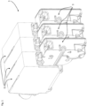
- a hydraulic control 1 comprises a plurality of hydraulic valves 11, 3 juxtaposed or stacked.
- Each hydraulic valve comprises a hydraulic distributor 11 and a corresponding electric actuator 3, a single electric actuator being associated with a single hydraulic distributor.
- Each hydraulic valve comprises a valve spool 13 slidably mounted in a body 19 comprising hydraulic channels 17.
- the position and configuration of the hydraulic channels as well as the profile (not shown) of the valve spool are adapted to the hydraulic function and are known per se and will not be described in further detail herein.
- the number of juxtaposed valves forming the hydraulic control 1 may vary depending on the application. Given the stacked arrangement of the valves, there is an advantage in the distributors as well as the actuators having a small footprint in the direction of juxtaposition.
- the electric actuator 3 therefore has a thickness E limited by the thickness of the hydraulic distributor 11.
- the electric actuator is fixed to the body 19 of the hydraulic distributor on an interface 21 of the body constituting one of the minor faces of the body.
- the electric actuator comprises an electric motor 6, an electronic circuit 10 comprising a circuit board 24, a linear displacement output member 4 coupled to the valve slide 13, a reduction gear 8 comprising gear wheels 22 coupling the motor to the output member, and a housing 2 in which the electric motor 6, the electronic circuit 10 and the reduction gear 8 are mounted.
- the output member 4 is connected to, or integral with, a rack 5 arranged in the housing 2 of the electric actuator.
- the motor 6 of the electric actuator is a closed-loop controlled brushless DC motor.
- a closed-loop controlled brushless DC motor makes it possible to transmit higher force peaks to the valve spool and to work more safely, in particular by having high reliability in positioning the output member of the electric actuator.
- the hydraulic control 1 may comprise, for each hydraulic valve, a pre-stressed return spring 15.
- the valve spool is pushed by the pre-stressed return spring 15 which moves it into a fail-safe position (so-called "fail safe” position) when the hydraulic system fails.
- the electric actuator must provide a high dynamic force.
- the choice of a closed-loop controlled brushless DC motor makes it possible to meet this requirement reliably, in an economical and compact configuration.
- the return spring 15 is mounted in a housing in the body 19 of the hydraulic distributor 11.
- the return spring 15 is mounted at the interface between the body 19 and the electric actuator, in a housing 23 formed in the housing 2 of the electric actuator.
- the axis of the output member 4 of the electric actuator 3 comprises a coupling part 7a mounted in a chamber 27 of the hydraulic distributor in which the return spring 15 is mounted.
- the chamber 27 is closed by a cap 25 mounted on the body of the hydraulic distributor, the chamber being filled with hydraulic fluid.
- a seal 29 is arranged between an orifice in the wall of the cap 25 and the axis 7a of the output member to ensure sealing between the hydraulic circuit and the electric actuator.
- the output member 4 may be coupled to the valve spool 13 by means of a removable connection configured to absorb positioning tolerances, for example in the form of a ball joint.
- the output member 4 may comprise a partially spherical coupling portion 31 inserted into a housing 33 at the end of the valve spool.
- a play-compensating spring 29 prestressed in the housing 33 presses the coupling portion 31 against a stop in the housing in order to eliminate the positioning play in the transverse direction T between the output member 4 and the valve slide 13.
- the housing 2 of the electric actuator comprises a base 14 and a cover 16 which closes the open side of the base.
- the base 14 of the housing forms a volume inside which the motor 6, the reducer 8 and the electronic circuit 10 are mounted.
- the cover 16 and the base 14 can advantageously be made of an injected plastic material, the edge of the cover 16 being welded to the edge of the base 14, for example by ultrasonic or laser welding, in order to ensure a hermetic seal between the cover 16 and the base 14.
- the motor 6 comprises a rotor 18 and a stator 20.
- the motor is in the form of a brushless DC motor.
- the rotor 18 comprises a magnet 30 forming a plurality of magnetic poles, for example a cylindrical magnet having a plurality of magnetized segments of alternating polarities arranged around the circumference of the cylinder.
- the rotor 18 may advantageously comprise a yoke 34 arranged coaxially within the cylindrical magnet, the yoke 34 being formed of a material with high magnetic permeability, such as soft iron.
- the yoke 34 and the magnet 30 are mounted in a support 68 of overmolded plastic, the support comprising flanges 69a, 69b extending radially above the axial ends of the yoke 34 and the magnet 30.
- the outer diameter of the yoke 34 is slightly less than the inner diameter of the magnet 30, the clearance between these two diameters being in a range of 50 to 200 microns, configured to compensate for a difference in thermal expansion between the yoke 34 and the magnet 30.
- the gap between the yoke 34 and the magnet 30 should be as small as possible while allowing sufficient clearance for differences in thermal expansion and also to allow easy assembly of the yoke 34 into the magnet 30.
- Overmolding the radial flanges over the axial ends of the yoke 34 and the magnet 30 advantageously allows the magnet 30 to be secured to the yoke 34 with the smallest desired clearance without requiring the use of glue or other securing means between the yoke 34 and the magnet 30.
- the support 68 may further comprise a pinion 40 secured to the support 68, for example advantageously formed from a plastic material injected at the same time as the support 68.
- the support 68 may be hollow in order to insert an axle 36, bearings 38 being mounted at the ends of the axle 36 in order to support the rotor in rotation in the housing 2.
- the stator 20 comprises a magnetic armature 42 and coils 44 mounted on arms of the magnetic armature 42.
- the magnetic armature 42 is made of a material with high magnetic permeability such as soft iron.
- the teeth 50 of the magnetic armature 42 define a number of magnetic poles.
- the coils 44 are formed by conductive wires connected to electrical terminals 54.
- the electrical terminals 54 may be formed from stamped parts.
- the pair of terminals 54 for the two ends of a wire 45 of a coil can be formed from a single stamped part overmolded by the plastic material supporting the armature 42 and the coils 44, a bridge 55 between the two terminals 54 then being cut after the overmolding operation or when the stamped part is still in the overmolding mold.
- the terminals may also be inserted into the plastic material supporting the armature.
- the electrical terminals 54 may advantageously comprise a connection portion 57 to be crimped to the coil wire, allowing automated and rapid manufacture of the coils and their interconnection to the electronic circuit 10.
- the terminals may advantageously comprise a part in the form of pins 53 oriented in an axial direction A configured to be inserted into complementary conductive holes of a circuit board 24 of the electronic circuit 10.
- the pins 53 are offset by a distance r in a radial direction in order to have a compact arrangement while ensuring sufficient distance between the pins for connection to the printed circuit.
- the magnetic armature 42 and the coils 44 can advantageously be directly overmolded in the plastic material forming the base 14, including the electrical terminals 54 ready to be coupled to the circuit board 24.
- the rotor 6 can be inserted axially into the stator which is directly integrated into the base of the housing.
- the reducer 8 comprises gear wheels 22 comprising a first wheel 46 and a second wheel 48.
- the first wheel 46 comprises a toothed crown 58 engaging the pinion 40 of the rotor 18.
- An axle 59 supporting the rotation of the first wheel 46 is mounted at the ends in housings formed in the base 14 and in the cover 16.
- the second wheel 48 comprises an axle 63 mounted at the ends of the housings formed in the base and the cover.
- axles 59 and 63 like the rotor 18 and the gear wheels 22 as well as the circuit board 24, can all be assembled in an axial direction A in the base 14 to simplify the assembly operations.
- the second wheel 48 of the reducer 8 comprises a pinion 62 which engages the rack 5.
- the rack 5 may be supported at its back by a bearing 79 so that the rack 5 comprises support on both sides opposite to guide them in the transverse direction T of linear movement of the output member 4.
- the toothed crown 60 of the second wheel 48 is arranged on the other side of the circuit board 24 with respect to the magnet 30 of the rotor 18.
- the circuit board 24 advantageously comprises cut-out portions 74, 72, a first cut-out 72 allowing the axial passage of the circuit board 24 to partially circumnavigate the pinion 40 and the toothed crown 58 of the first wheel 46 which is arranged at the height of the circuit board.
- the circuit board 24 can therefore be arranged just above an axial end of the magnet 30 of the rotor 18, Hall effect position sensors 26 being arranged on the circuit board 24 above the magnetic segments 32 of the magnet 30.
- the magnetic probes 26a, 26b, 26c may advantageously be arranged close to one another, the probes being in particular spaced apart by an angle ⁇ around the axis of rotation of the rotor of less than 60 degrees. In other words, the probes are arranged in an arc of a circle around the rotor of less than 60 degrees. In the example illustrated, there are three magnetic probes 26a, 26b, 26c, but in variants it is possible to have two, four, or more probes to detect the position and speed of the rotor. For a rotor formed by 5 pairs of poles, the probes 26a, 26b, 26c may in particular have an angle of 24 degrees between adjacent probes in order to form an electrical angle of 120 degrees.
- the arrangement of the magnetic probes 26a, 26b, 26c according to the embodiment of the invention described above makes it possible to reduce the size of the circuit board 24 and leave more space for the stator 20 and the reducer 8 in order to reduce the size, in particular in the axial direction A of the actuator.
- the magnetic probes 26 make it possible to detect the position and speed of the rotor 18 in a very compact and economical configuration.
- the stator 20 of the motor comprises a magnetic armature 42, three coils 44 mounted on branches of the magnetic armature arranged asymmetrically around the rotor 18, and in particular arranged in an arc of a circle around the rotor 18 of less than 180 degrees. Poles of the stator on the opposite side of the coils 44 are formed by teeth 50 of the armature without coils, this making it possible to have a stator 30 of small diameter on the opposite side of the coils.
- the axis 59 of the first wheel 46 of the reducer 8 is mounted next to the part of the stator 20 without coils in order to have a small distance with the axis of the rotor 18 to reduce the diameter of the first wheel 46, for a compact configuration.
- the teeth 50 may have different widths (in the direction of rotation of the rotor), for example a first series of teeth with a greater width than a second series of intercalated teeth as illustrated in the Figure 15a , or the 50 teeth may all be of identical width as shown in the Figure 15b .
- the ring gear 60 of the second wheel 48 is disposed above the circuit board 24, the pinion 62 of the second wheel 62 extending through a cutout 74 of the circuit board to engage the rack 5 disposed below the circuit board 24.
- the second wheel 48 may advantageously comprise a position marker 64 disposed on a face of the ring gear 60 facing the circuit board 24.
- a position detector 28 may be mounted on the circuit board 24 below the position marker 64.
- the position detector 28 may be in the form of a Hall effect sensor and the position marker 64 may be in the form of a ring magnet, for example a segmented ring magnet allowing the Hall effect sensor to detect the movement of the second wheel 48.
- the position detector 28 of the toothed crown 60 makes it possible to provide the position of the output member 4.
- the integration of the position detector 28 directly on the circuit board 24 makes it possible to have a particularly compact and economical arrangement while ensuring the reliability of positioning of the output member.
- the position marker 64 and the probe can be optical.
- the position marker 64 can comprise light and dark segments and the position detector 28 on the circuit board 24 comprises a light source and an optical sensor for detecting the passage of the segments.
- the electronic circuit 10 may include capacitors 66 used in particular for filtering electrical interference. These capacitors 66 take up a certain volume and may be arranged on the circuit board 24 oriented towards the base 14 of the housing 2, on the same side as the rotor 18.
- the electronic circuit 10 may be connected to an external control by a connector 12, the connector housing being integrally formed with the base 14 of the housing. Electrical terminals 78 of the connector 12 may be overmolded directly into the base 14 of the housing, the terminals 78 comprising connection portions in the form of axially oriented pins 81 for a press-fit type connection with conductive holes of the circuit board 24 when the latter is axially inserted into the base 14 of the housing during its assembly.
- the overmolding of the stator 20 of the motor 6, the connection of the coils 44 of the motor, and the electrical terminals 78 of the connector 12 directly in the base 14 of the housing, also forming the bearings for the rotor bearings as well as the housings for the axes of rotation of the gear wheels in the base makes it possible to provide an economical and very compact actuator.
- the arrangement of the second gear wheel 60 of the reducer 8 above the circuit board 24, engaging the first gear wheel 58 below the circuit board 24, with the pinion 62 passing through a cutout in the board 24, makes it possible to have a small footprint in the axial direction A, while offering a large reduction, which makes it possible to use a brushless motor at high speed. and providing a high residual torque.
- the arrangement of the motor coils as well as the position probes 26a, 26b, 26c of the rotor in a reduced arc of a circle makes it possible to arrange the first gear wheel close to the rotor while keeping the axial height of the actuator low.
- the electric actuator according to the invention is very compact and is notably characterized by dimension ratios (see figures 8 , 10, 11, 12 , 15 ) described below.
- the ratio e/E of the thickness e of the stator, including the winding thickness, to the thickness E of the electric actuator is greater than 0.45, the direction of measurement of the thickness being the direction of stacking or juxtaposition of the hydraulic valves forming the hydraulic control.
- the ratio L/E of the length L of the electric actuator 3 to the thickness E of the electric actuator is greater than 2.5 and less than 4, the direction of measurement of the length being orthogonal to the direction of stacking of the hydraulic valves forming the hydraulic control and the direction of actuation of the valve slide.
- the ratio H / E of the height H of the electric actuator 3 to the thickness E of the electric actuator is greater than 2 and less than 3.5, the direction of measurement of the height being the direction of actuation of the valve slide.
- examples of electric actuators may have the following dimensions: ⁇ i>Dimensions in mm ⁇ /i> Actuator Stator Thickness (e) Ratios and differences Thickness ( E ) Length ( L ) height ( H ) THE HEY e / E Ee 40 125 100 22 3.1 2.5 0.55 18 32 125 100 16 3.9 3.1 0.50 16 48 125 100 30 2.6 2.1 0.63 18
Landscapes
- Engineering & Computer Science (AREA)
- General Engineering & Computer Science (AREA)
- Power Engineering (AREA)
- Mechanical Engineering (AREA)
- Microelectronics & Electronic Packaging (AREA)
- Physics & Mathematics (AREA)
- Fluid Mechanics (AREA)
- Connection Of Motors, Electrical Generators, Mechanical Devices, And The Like (AREA)
Description
- La présente invention concerne le domaine des commandes hydrauliques, notamment comprenant des vannes hydrauliques, chacune comprenant un distributeur hydraulique et un actionneur électrique.
- Des commandes hydrauliques sont utilisées dans de nombreux domaines, par exemple pour des véhicules agricoles, des engins de chantier, des grues, et d'autres appareils de levage et de manutention.
- Certaines commandes hydrauliques comprennent une pluralité de vannes hydrauliques juxtaposées, chaque vanne formée par un distributeur hydraulique couplé à un actionneur électrique actionnant un axe de commande hydraulique, notamment un tiroir de vanne. Un actionneur électrique pour la commande de distributeurs hydrauliques est décrit par exemple dans le brevet
US 7,591,448 . - Les vannes hydrauliques d'une commande hydraulique sont disposées d'une manière juxtaposée, espacées d'une distance que les actionneurs des distributeurs doivent respecter. L'axe de commande du distributeur hydraulique est poussé par un ressort précontraint qui le déplace dans une position de sécurité (position dite « fail safe ») lorsque le système hydraulique tombe en panne. Pour vaincre la force du ressort et assurer un fonctionnement très dynamique, l'actionneur doit fournir une force dynamique élevée.
- En raison de l'environnement exigeant dans lequel l'actionneur est utilisé dans beaucoup d'applications hydrauliques, il est aussi important que l'actionneur soit robuste et fiable, pouvant supporter des vibrations, des changements de température élevés et des chocs.
- Le coût de l'actionneur est également un facteur important.
- Il est également important, pour assurer un fonctionnement fiable, de connaître la position de l'axe de commande de manière précise et fiable.
- L'actionneur électrique décrit dans le brevet
US 7,591,448 est certes compact et précis, toutefois le coût de production d'un tel actionneur est élevé en raison du nombre de composants, le coût de fabrication des composants, et la complexité de l'assemblage. - Un objet de l'invention est de fournir une commande hydraulique compacte, performante, et fiable.
- Il est avantageux de fournir une commande hydraulique qui est économique à fabriquer.
- Un objet particulier de l'invention est de fournir une commande hydraulique avec un actionneur électrique plat pour un distributeur hydraulique, ayant une grande densité de couple pour sa taille et qui est économique à fabriquer.
- Un autre objet de l'invention est de fournir un actionneur électrique pour une commande hydraulique, compact, performant et fiable.
- Il est avantageux de fournir un actionneur électrique pour une commande hydraulique, ayant un haut rendement.
- Un objet de l'invention est réalisé par une commande hydraulique selon la revendication indépendante.
- Les revendications dépendantes décrivent des caractéristiques avantageuses de l'invention. Dans la présente invention, on décrit une commande hydraulique comprenant au moins une vanne hydraulique, chaque vanne hydraulique comprenant un distributeur hydraulique et un actionneur électrique. Le distributeur hydraulique comprend un tiroir de vanne monté coulissant dans un corps comprenant des canaux hydrauliques. L'actionneur électrique est fixé au corps du distributeur hydraulique et comprend un moteur électrique, un circuit électronique comportant une carte de circuit, un organe de sortie à déplacement linéaire couplé au tiroir de commande, un réducteur comportant des roues d'engrenage couplant le moteur à l'organe de sortie, et un boîtier dans lequel le moteur électrique, le circuit électronique et le réducteur sont montés.
- Selon un aspect de l'invention, les roues d'engrenage incluent au moins une première roue et une deuxième roue, la deuxième roue étant disposée du côté d'un couvercle du boîtier et le moteur électrique étant monté dans la base du boîtier. La première roue comprenant une couronne dentée engageant un pignon du rotor et un pignon engageant une couronne dentée de la deuxième roue. La carte de circuit est disposée entre la couronne dentée de la deuxième roue et l'aimant du rotor du moteur électrique.
- La couronne dentée de la première roue est disposée à la hauteur de la carte du circuit, dans une découpe de la carte de circuit.
- Avantageusement, comparé avec un moteur pas-à-pas utilisé pour l'actionnement d'une vanne hydraulique dans les commandes hydrauliques conventionnels, l'utilisation d'un moteur à courant continu sans balais commandé en boucle fermée permet de transmettre de plus forts pics de force au tiroir de vanne et de travailler de manière plus sécurisé, notamment en ayant une grande fiabilité de positionnement de l'organe de sortie de l'actionneur électrique.
- Il convient de préciser qu'une pluralité de distributeurs hydrauliques empilés ou juxtaposés peut comprendre un corps (comprenant des canaux hydrauliques) commun et monobloc, ou une pluralité de corps (p. ex. un par vanne) assemblés.
- Avantageusement, l'actionneur électrique selon l'invention est très compact et notamment est caractérisé par l'une ou plusieurs des ratios suivants :
- un ratio e/E d'une épaisseur e du stator du moteur électrique, incluant l'épaisseur de bobinage, sur une épaisseur E de l'actionneur électrique est supérieur à 0.45, la direction de mesure de l'épaisseur étant une direction d'empilement ou de juxtaposition des vannes hydrauliques formant la commande hydraulique.
- un ratio L/E d'une longueur L de l'actionneur électrique sur une épaisseur E de l'actionneur électrique est supérieur à 2.5 et inférieur à 4, la direction de mesure de la longueur étant orthogonale à une direction d'empilement des vannes hydrauliques formant la commande hydraulique et une direction d'actionnement du tiroir de vanne.
- un ratio H/E d'une hauteur H de l'actionneur électrique sur une épaisseur E de l'actionneur électrique est supérieur à 2 et inférieur à 3.5, la direction de mesure de la hauteur étant la direction d'actionnement du tiroir de vanne.
- Le moteur électrique comporte un stator et un rotor, le rotor comprenant un aimant définissant une pluralité de pôles de rotor et le stator comprenant une armature magnétique et une pluralité de bobines montées sur l'armature magnétique.
- Dans une forme d'exécution avantageuse, la carte de circuit est disposée au-dessus d'une extrémité axiale de l'aimant du rotor, des sondes magnétiques, par exemple des sondes à effet Hall, étant disposées sur la carte de circuit au-dessus des segments magnétiques de l'aimant, les sondes magnétiques étant disposées dans un arc de cercle autour du rotor d'un angle (α) inférieur à 60 degrés.
- Dans une forme d'exécution avantageuse, le rotor comprend un aimant sous forme cylindrique et une culasse disposée coaxialement à l'intérieur de l'aimant cylindrique, la culasse et l'aimant étant montés dans un support en matière plastique surmoulée, le support comprenant des brides s'étendant radialement au-dessus des extrémités axiales de la culasse et de l'aimant.
- Le moteur est un moteur à courant continu sans balais commandé en boucle fermé.
- Dans une forme d'exécution avantageuse, les bobines sont montées sur des branches de l'armature magnétique disposées dans un arc de moins de 180 degrés autour de l'axe de rotation du rotor, un axe de rotation de la première roue du réducteur étant monté à côté d'une partie du stator sans bobines.
- Dans une forme d'exécution avantageuse, la deuxième roue comprend un marqueur de position disposé sur une face de la couronne dentée vis-à-vis de la carte de circuit et un détecteur de position est monté sur la carte de circuit sous le marqueur de position.
- Dans une forme d'exécution avantageuse, le détecteur de position est sous forme d'un capteur à effet Hall et le marqueur de position est sous forme d'un aimant annulaire.
- Dans une forme d'exécution avantageuse, la deuxième roue du réducteur comprend un pignon qui engage une crémaillère connectée à l'organe de sortie à déplacement linéaire.
- Dans une forme d'exécution avantageuse, des fils conducteurs des bobines sont connectés à des bornes électriques formées de pièces étampées insérées dans ou surmoulées par une matière plastique formant intégralement la base du boitier et supportant l'armature et les bobines.
- Dans une forme d'exécution avantageuse, l'actionneur comprend un connecteur pour connecter le circuit électronique à une commande externe, un boîtier du connecteur étant formé de manière solidaire avec la base du boîtier, des bornes électriques du connecteur étant surmoulées dans la base du boîtier et comprenant des parties de connexion orientées axialement pour une connexion avec la carte de circuit.
- Dans une forme d'exécution avantageuse, l'armature magnétique et les bobines y compris avec des bornes électriques pour la connexion à une carte de circuit sont surmoulées dans la matière plastique formant la base du boitier.
- Dans une forme d'exécution avantageuse, le jeu entre le diamètre extérieur de la culasse et le diamètre intérieur de l'aimant est dans une gamme de 50 à 200 microns.
- Dans une forme d'exécution avantageuse, le support du rotor comprend un pignon solidaire du support formé d'une matière plastique injectée.
- Dans une forme d'exécution, la commande hydraulique comprend un ressort de rappel précontraint agissant sur le tiroir de vanne. Dans une variante, le ressort de rappel est monté à une interface entre le corps du distributeur hydraulique et l'actionneur électrique, dans un logement formé dans le boitier de l'actionneur électrique.
- D'autres buts et aspects avantageux de l'invention apparaîtront à la lecture des revendications et/ou de la description détaillée ci-après de formes d'exécution de l'invention en relation avec les figures, dans lesquelles :
- La
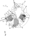
Fig. 1 est une vue en perspective d'une commande hydraulique selon une première forme d'exécution de l'invention ; - La
Fig. 2 est une vue en coupe de la commande hydraulique selon lafigure 1 ; - La
Fig. 3 est une vue d'un actionneur électrique de la commande hydraulique selon lafigure 1 ; - La
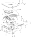
Fig. 4 est une vue en perspective éclatée de l'actionneur électrique selon lafigure 3 ; - La
Fig. 5 est une vue en coupe à travers la ligne C-C de l'actionneur selon lafigure 3 ; - La
Fig. 6 est une vue en coupe à travers la ligne E-E de l'actionneur selon lafigure 3 ; - La
Fig. 7 est une vue en coupe à travers la ligne D-D de l'actionneur selon lafigure 3 ; - La
Fig. 7a est une vue agrandie d'une partie de lafigure 7 ; - La
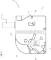
Fig. 8 est une vue en perspective d'une commande hydraulique selon une deuxième forme d'exécution de l'invention ; - La
Fig. 9 est une vue en coupe de la commande hydraulique selon lafigure 8 ; - La
Fig. 10 est une vue d'un actionneur électrique de la commande hydraulique selon lafigure 8 ; - La
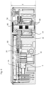
Fig. 11 est une vue en coupe à travers la ligne A-A de l'actionneur selon lafigure 10 ; - La
Fig. 12 est une vue en coupe à travers la ligne B-B de l'actionneur selon lafigure 10 ; - La
Fig. 13 est une vue en coupe de l'actionneur selon lafigure 10 ; - La
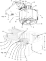
Fig. 14 est une vue en perspective d'un rotor d'un actionneur électrique d'une commande hydraulique selon une forme d'exécution de l'invention ; - La
Fig. 15a est une vue en perspective d'un stator d'un actionneur électrique d'une commande hydraulique selon une forme d'exécution de l'invention ; - La
Fig. 15b est une vue en perspective d'un stator d'un actionneur électrique d'une commande hydraulique selon une forme d'exécution de l'invention. - Faisant référence aux figures, commençant par les
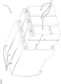
figures 1 ,2 ,8 et9 , une commande hydraulique 1 comprend une pluralité de vannes hydrauliques 11, 3 juxtaposées ou empilées. Chaque vanne hydraulique comprend un distributeur hydraulique 11 et un actionneur électrique 3 correspondant, un seul actionneur électrique étant associé à un seul distributeur hydraulique. - Chaque vanne hydraulique comprend un tiroir de vanne 13 monté coulissant dans un corps 19 comprenant des canaux hydrauliques 17. La position et la configuration des canaux hydrauliques ainsi que le profil (non-illustré) du tiroir de vanne sont adaptés à la fonction hydraulique et sont en soi connus et ne seront pas décrits plus en détail dans la présente. Le nombre de vannes juxtaposées formant la commande hydraulique 1 peut varier en fonction de l'application. Compte tenu de l'arrangement empilé des vannes, il y a un avantage à ce que les distributeurs ainsi que les actionneurs aient un encombrement faible dans la direction de la juxtaposition. L'actionneur électrique 3 a donc une épaisseur E limitée par l'épaisseur du distributeur hydraulique 11. L'actionneur électrique est fixé au corps 19 du distributeur hydraulique sur une interface 21 du corps constituant l'une des faces mineures du corps.
- Faisant référence notamment aux
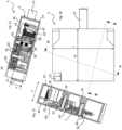
figures 3-7a et10-13 l'actionneur électrique comprend un moteur électrique 6, un circuit électronique 10 comportant une carte de circuit 24, un organe de sortie 4 à déplacement linéaire couplé au tiroir de vanne 13, un réducteur 8 comportant des roues d'engrenage 22 couplant le moteur à l'organe de sortie, et un boîtier 2 dans lequel le moteur électrique 6, le circuit électronique 10 et le réducteur 8 sont montés. L'organe de sortie 4 est connecté, ou solidaire avec, une crémaillère 5 disposée dans le boîtier 2 de l'actionneur électrique. - Le moteur 6 de l'actionneur électrique est un moteur à courant continu sans balais commandé en boucle fermé. Comparé avec un moteur pas-à-pas utilisé pour l'actionnement d'une vanne hydraulique dans les commandes hydrauliques conventionnelles, l'utilisation d'un moteur à courant continu sans balais commandé en boucle fermée permet de transmettre de plus forts pics de force au tiroir de vanne et de travailler de manière plus sécurisée, notamment en ayant une grande fiabilité de positionnement de l'organe de sortie de l'actionneur électrique.
- La commande hydraulique 1 peut comprendre, pour chaque vanne hydraulique, un ressort de rappel 15 précontraint. Le tiroir de vanne est poussé par le ressort de rappel 15 précontraint qui le déplace dans une position de sécurité (position dite « fail safe ») lorsque le système hydraulique tombe en panne. Pour vaincre la force du ressort de rappel 15 et assurer un fonctionnement très dynamique, l'actionneur électrique doit fournir une force dynamique élevée. Le choix d'un moteur à courant continu sans balais commandé en boucle fermée permet de répondre à cette exigence de manière fiable, dans une configuration économique et compacte.
- Dans une première variante, illustrée dans les
figures 1 et2 , le ressort de rappel 15 est monté dans un logement dans le corps 19 du distributeur hydraulique 11. - Dans une deuxième variante, illustrée dans les
figures 8 et9 , le ressort de rappel 15 est monté à l'interface entre le corps 19 et l'actionneur électrique, dans un logement 23 formé dans le boitier 2 de l'actionneur électrique. L'axe de l'organe de sortie 4 de l'actionneur électrique 3 comprend une partie d'accouplement 7a montée dans une chambre 27 du distributeur hydraulique dans lequel le ressort de rappel 15 est monté. La chambre 27 est fermée par un capuchon 25 monté sur le corps du distributeur hydraulique, la chambre étant remplie de fluide hydraulique. Un joint 29 est disposé entre un orifice de la paroi du capuchon 25 et l'axe 7a de l'organe de sortie pour assurer l'étanchéité entre le circuit hydraulique et l'actionneur électrique. Pour l'assemblage de l'actionneur 3 et du distributeur 11, la crémaillère 5 est préassemblé à l'organe de sortie 4, et lors de la fixation de l'actionneur électrique 3 au distributeur hydraulique 11, insérée dans le boitier 2 entre le roulement de support 79 et le pignon 62. - L'organe de sortie 4 peut être couplée au tiroir de vanne 13 au moyen d'une liaison amovible configurée pour absorber des tolérances de positionnement, par exemple sous forme d'un joint à rotule. Dans cet exemple, l'organe de sortie 4 peut comprendre une partie d'accouplement 31 partiellement sphérique insérée dans un logement 33 à l'extrémité du tiroir de vanne. Un ressort de rattrapage de jeu 29 précontraint dans le logement 33 appui la partie d'accouplement 31 contre une butée dans le logement afin d'éliminer le jeu de positionnement dans la direction transversale T entre l'organe de sortie 4 et le tiroir de vanne 13.
- Le boîtier 2 de l'actionneur électrique comprend une base 14 et un couvercle 16 qui ferme le côté ouvert de la base. La base 14 du boitier forme un volume à l'intérieur duquel le moteur 6, le réducteur 8 et le circuit électronique 10 sont montés. Le couvercle 16 et la base 14 peuvent avantageusement être fabriqués en une matière plastique injectée, le bord du couvercle 16 étant soudé au bord de la base 14, par exemple par soudage par ultrasons ou par laser, afin d'assurer une fermeture hermétique entre le couvercle 16 et la base 14.
- Le moteur 6 comprend un rotor 18 et un stator 20. Le moteur est sous forme d'un moteur sans balais à courant continu (brushless DC motor).
- Dans une forme d'exécution, le rotor 18 comprend un aimant 30 formant une pluralité de pôles magnétiques, par exemple un aimant sous forme cylindrique comportant une pluralité de segments magnétisés de polarités alternées disposés sur la circonférence du cylindre. Le rotor 18 peut avantageusement comprendre une culasse 34 disposée coaxialement à l'intérieur de l'aimant cylindrique, la culasse 34 étant formée d'un matériau avec une haute perméabilité magnétique, tel que du fer doux.
- Dans une forme d'exécution avantageuse, la culasse 34 et l'aimant 30 sont montés dans un support 68 en matière plastique surmoulée, le support comprenant des brides 69a, 69b s'étendant radialement au-dessus des extrémités axiales de la culasse 34 et de l'aimant 30. Le diamètre extérieur de la culasse 34 est légèrement inférieur au diamètre intérieur de l'aimant 30, le jeu entre ces deux diamètres étant dans une gamme de 50 à 200 microns, configurée pour compenser une différence de dilatation thermique entre la culasse 34 et l'aimant 30. Afin de maximiser l'efficacité magnétique et en conséquence le couple résiduel du moteur, l'espace entre la culasse 34 et l'aimant 30 devrait être aussi faible que possible tout en permettant un jeu suffisant pour les différences de dilation thermique et aussi pour permettre un assemblage aisé de la culasse 34 dans l'aimant 30.
- Le surmoulage des brides radiales au-dessus des extrémités axiales de la culasse 34 et de l'aimant 30 permet avantageusement de fixer l'aimant 30 à la culasse 34 avec le plus faible jeu voulu sans nécessiter l'utilisation d'une colle ou d'un autre moyen de fixation entre la culasse 34 et l'aimant 30.
- Le support 68 peut en outre comprendre un pignon 40 solidaire du support 68, par exemple avantageusement formé d'une matière plastique injectée en même temps que le support 68. Le support 68 peut être creux afin d'insérer un axe 36, des roulements 38 étant montés aux extrémités de l'axe 36 afin de supporter le rotor en rotation dans le boîtier 2.
- Le stator 20 comprend une armature magnétique 42 et des bobines 44 montées sur des bras de l'armature magnétique 42. L'armature magnétique 42 est dans un matériau avec une haute perméabilité magnétique tel que du fer doux. Les dents 50 de l'armature magnétique 42 définissent un certain nombre de pôles magnétiques. Les bobines 44 sont formées par des fils conducteurs connectés à des bornes électriques 54.
- Les bornes électriques 54 peuvent être formées de pièces étampées.
- Dans une forme d'exécution illustrée dans la
figure 15a , la paire de bornes 54 pour les deux extrémités d'un fil 45 d'une bobine peut être formée d'une seule pièce étampée surmoulée par la matière plastique supportant l'armature 42 et les bobines 44, un pont 55 entre les deux bornes 54 étant ensuite découpé après l'opération de surmoulage ou lorsque la pièce étampée est encore dans le moule de surmoulage. - Les bornes peuvent aussi être insérées dans la matière plastique supportant l'armature. Les bornes électriques 54 peuvent avantageusement comprendre une partie de connexion à sertir 57 au fil de la bobine, permettant une fabrication automatisée et rapide des bobines et de leur interconnexion au circuit électronique 10.
- Les bornes peuvent avantageusement comprendre une partie sous forme de broches 53 orientés dans une direction axiale A configurés pour être insérés dans des trous conducteurs complémentaires d'une carte de circuit 24 du circuit électronique 10.
- Dans une forme d'exécution illustrée dans la
figure 15b , les broches 53 sont décalées par une distance r dans une direction radiale afin d'avoir un arrangement compact tout en assurant une distance suffisante entre les broches pour la connexion au circuit imprimé. - L'armature magnétique 42 et les bobines 44 peuvent avantageusement être directement surmoulées dans la matière plastique formant la base 14, y compris avec les bornes électriques 54 prêtes à être couplées à la carte de circuit 24.
- Le rotor 6 peut être inséré axialement dans le stator qui est directement intégré dans la base du boîtier.
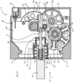
- Le réducteur 8 comprend des roues d'engrenage 22 comprenant une première roue 46 et une deuxième roue 48. La première roue 46 comprend une couronne dentée 58 engageant le pignon 40 du rotor 18. Un axe 59 supportant la rotation de la première roue 46 est monté aux extrémités dans des logements formés dans la base 14 et dans le couvercle 16. De même, la deuxième roue 48 comprend un axe 63 monté aux extrémités des logements formés dans la base et le couvercle.
- Les axes 59 et 63, comme le rotor 18 et les roues d'engrenage 22 ainsi que la carte de circuit 24, peuvent tous être assemblés dans une direction axiale A dans la base 14 permettant de simplifier les opérations d'assemblage.
- La deuxième roue 48 du réducteur 8 comprend un pignon 62 qui engage la crémaillère 5. La crémaillère 5 peut être supportée à son dos par un roulement 79 de sorte à ce que la crémaillère 5 comprenne un support des deux côtés opposés pour les guider dans la direction transversale T de déplacement linéaire de l'organe de sortie 4.
- Par rapport au rotor 18 du moteur 6, la couronne dentée 60 de la deuxième roue 48 est disposée de l'autre côté de la carte de circuit 24 par rapport à l'aimant 30 du rotor 18. La carte de circuit 24 comprend avantageusement des parties découpées 74, 72, une première découpe 72 permettant le passage axial de la carte de circuit 24 pour faire le tour partiel du pignon 40 et de la couronne dentée 58 de la première roue 46 qui est disposée à la hauteur de la carte de circuit. La carte de circuit 24 peut donc être disposée juste au-dessus d'une extrémité axiale de l'aimant 30 du rotor 18, des capteurs de position à effet Hall 26 étant disposés sur la carte de circuit 24 au-dessus des segments magnétiques 32 de l'aimant 30.
- Les sondes magnétiques 26a, 26b, 26c, par exemple des capteurs à effet Hall, peuvent avantageusement être disposées à proximité l'une de l'autre, les sondes étant notamment écartées d'un angle α autour de l'axe de rotation du rotor inférieur à 60 degrés. En d'autres termes, les sondes sont disposées dans un arc de cercle autour du rotor inférieur à 60 degrés. Dans l'exemple illustré, il y a trois sondes magnétiques 26a, 26b, 26c, mais dans des variantes il est possible d'avoir deux, quatre, ou plus de sondes pour détecter la position et la vitesse du rotor. Pour un rotor formé de 5 paires de pôles, les sondes 26a, 26b, 26c peuvent notamment avoir un angle de 24 degrés entre sondes adjacentes afin de former un angle électrique de 120 degrés. La disposition des sondes magnétiques 26a, 26b, 26c selon la forme d'exécution de l'invention décrite ci-dessus, permet de réduire la taille de la carte de circuit 24 et laisser plus de place pour le stator 20 et le réducteur 8 afin de réduire l'encombrement, notamment dans la direction axiale A de l'actionneur. Les sondes magnétiques 26 permettent de détecter la position et la vitesse du rotor 18 dans une configuration très compacte et économe.
- Le stator 20 du moteur comprend une armature magnétique 42, trois bobines 44 montées sur des branches de l'armature magnétique disposées de manière asymétrique autour du rotor 18, et notamment disposées dans un arc de cercle autour du rotor 18 de moins de 180 degrés. Des pôles du stator du côté opposé des bobines 44 sont formés par des dents 50 de l'armature sans bobines, cela permettant d'avoir un stator 30 de faible diamètre du côté opposé des bobines. L'axe 59 de la première roue 46 du réducteur 8 est monté à côté de la partie du stator 20 sans bobines afin d'avoir une faible distance avec l'axe du rotor 18 pour réduire le diamètre de la première roue 46, pour une configuration compacte.
- Les dents 50 peuvent avoir des largeurs (dans le sens de la rotation du rotor) différentes, par exemple une première série de dents avec une largeur plus grande qu'une deuxième série de dents intercalées comme illustré dans la
figure 15a , ou les dents 50 peuvent tous être de largeur identique comme illustré dans lafigure 15b . - La couronne dentée 60 de la deuxième roue 48 est disposée au-dessus de la carte de circuit 24, le pignon 62 de la deuxième roue 62 s'étendant à travers une découpe 74 de la carte de circuit pour engager la crémaillère 5 disposée en-dessous de la carte de circuit 24. La deuxième roue 48 peut avantageusement comprendre un marqueur de position 64 disposé sur une face de la couronne dentée 60 vis-à-vis de la carte de circuit 24. Un détecteur de position 28 peut être monté sur la carte de circuit 24 sous le marqueur de position 64. Dans une variante avantageuse, le détecteur de position 28 peut être sous forme d'un capteur à effet Hall et le marqueur de position 64 peut être sous forme d'un aimant annulaire, par exemple un aimant annulaire segmenté permettant au capteur à effet Hall de détecter le déplacement de la deuxième roue 48. La deuxième roue 48 étant couplée directement à la crémaillère 5, le détecteur de position 28 de la couronne dentée 60 permet de fournir la position de l'organe de sortie 4. L'intégration du détecteur de position 28 directement sur la carte de circuit 24 permet d'avoir une disposition particulièrement compacte et économe tout en assurant la fiabilité de positionnement de l'organe de sortie. Dans une variante, le marqueur de position 64 et la sonde peuvent être optiques. Par exemple le marqueur de position 64 peut comprendre des segments clairs et foncés et le détecteur de position 28 sur la carte de circuit 24 comprend une source lumineuse et un capteur optique pour détecter le passage des segments.
- Le circuit électronique 10 peut comprendre des condensateurs 66 servant notamment au filtrage d'interférences électriques. Ces condensateurs 66 prennent un certain volume et peuvent être disposés sur la carte de circuit 24 orientés vers la base 14 du boîtier 2, du même côté que le rotor 18.
- Le circuit électronique 10 peut être connecté à une commande externe par un connecteur 12, le boîtier du connecteur étant formé de manière solidaire avec la base 14 du boîtier. Des bornes électriques 78 du connecteur 12 peuvent être surmoulées directement dans la base 14 du boîtier, les bornes 78 comprenant des parties de connexion sous forme de broches 81 orientées axialement pour une connexion de type « press-fit » avec des trous conducteurs de la carte de circuit 24 lorsque celui-ci est inséré axialement dans la base 14 du boîtier lors de son assemblage.
- Avantageusement, le surmoulage du stator 20 du moteur 6, de la connectique des bobines 44 du moteur, et des bornes électriques 78 du connecteur 12 directement dans la base 14 du boîtier, en formant aussi les paliers pour les roulements du rotor ainsi que les logements pour les axes de rotation des roues d'engrenage dans la base permettent de fournir un actionneur économe et très compact. La disposition de la deuxième roue d'engrenage 60 du réducteur 8 au-dessus de la carte de circuit 24, engageant la première roue d'engrenage 58 en-dessous de la carte de circuit 24, avec le pignon 62 passant à travers une découpe dans la carte 24, permet d'avoir un faible encombrement dans la direction axiale A, tout en offrant une grande réduction, ce qui permet d'utiliser un moteur sans balais à haute vitesse et fournissant un couple résiduel élevé. Par ailleurs, la disposition des bobines du moteur ainsi que des sondes de position 26a, 26b, 26c du rotor dans un arc de cercle réduit, permettent de disposer la première roue d'engrenage proche du rotor tout en gardant la hauteur axiale de l'actionneur faible.
- L'actionneur électrique selon l'invention est très compact et notamment est caractérisé par des ratios de dimensions (voir
figures 8 ,10, 11, 12 ,15 ) décrits ci-dessous. - Selon un aspect avantageux de l'invention, le ratio e/E de l'épaisseur e du stator, incluant l'épaisseur de bobinage, sur l'épaisseur E de l'actionneur électrique est supérieur à 0.45, la direction de mesure de l'épaisseur étant la direction d'empilement ou de juxtaposition des vannes hydrauliques formant la commande hydraulique.
- Selon un aspect avantageux de l'invention, le ratio L/E de la longueur L de l'actionneur électrique 3 sur l'épaisseur E de l'actionneur électrique est supérieur à 2.5 et inférieur à 4, la direction de mesure de la longueur étant orthogonale à la direction d'empilement des vannes hydrauliques formant la commande hydraulique et la direction d'actionnement du tiroir de vanne .
- Selon un aspect avantageux de l'invention, le ratio H/E de la hauteur H de l'actionneur électrique 3 sur l'épaisseur E de l'actionneur électrique est supérieur à 2 et inférieur à 3.5, la direction de mesure de la hauteur étant la direction d'actionnement du tiroir de vanne.
- Ces ratios avantageux permettant de fournir un actionneur compact sont résumés dans le tableau suivant :
L/E H/E e/E >2.5 >2 >0.45 <4 <3.5 - A titre d'illustration, des exemples d'actionneurs électriques selon des formes d'exécution avantageuses de l'invention peuvent avoir les dimensions suivantes :
Dimensions en mm Actionneur Stator Epaisseur (e) Ratios et différences Epaisseur (E) Longueur (L) hauteur (H) L/E H/E e/E E-e 40 125 100 22 3.1 2.5 0.55 18 32 125 100 16 3.9 3.1 0.50 16 48 125 100 30 2.6 2.1 0.63 18 -
- Commande hydraulique 1
- Vanne hydraulique
-
Distributeur hydraulique 11
- Corps 19
- Tiroir de vanne 13
- Logement 33
- Ressort de rattrapage de jeu 19
- Ressort de rappel 15
- Canaux hydrauliques 17
- Interface 21
- Capuchon 25
- chambre de ressort 27
- joint 29
- Actionneur 3
-
Boitier 2
- Base 14
- Couvercle 16
- Logement 23 (pour recevoir le ressort de rappel)
-
Organe de sortie 4
- Crémaillère 5
Roulement de guidage 79 - Axe 7
- Partie d'accouplement 31
- Tête sphérique
- Crémaillère 5
-
Moteur 6
-
Rotor 18
- Aimant 30
- Pôles 32
- Culasse 34
- Axe 36
- Paliers 38
- Roulement
- Pignon 40
- Support 68 (surmoulage)
- bride 69
-
Stator 20
- Armature magnétique 42
- Dents 50
- Bobine 44
- Fil conducteur 45
- Bornes électriques 54
- Pont 55
- partie de connexion à sertir 57
- broches de connexion 53
- surmoulage 61
-
Rotor 18
- Réducteur 8
- Roues d'engrenage 22
- Première roue 46
- Pignon 56
- Couronne dentée 58
- Axe 59
- Deuxième roue 48
- Couronne dentée 60
- Marqueur de position (aimant) 64
- Pignon 62
- Axe 63
- Première roue 46
-
Circuit électronique 10
-
Carte de circuit 24
- découpe 72 (pour la première roue d'engrenage)
- découpe 74 (pour pignon de sortie)
- Capteur de position du rotor 26
- Sondes magnétiques (à effet Hall) 26a, 26b, 26c
- Capteur de position de la deuxième roue 28
- Condensateurs 66
-
Carte de circuit 24
- Connecteur 12
- Bornes 78
- broches 81
Claims (14)
- Commande hydraulique (1) comprenant au moins une vanne hydraulique, chaque vanne hydraulique comportant un distributeur hydraulique (11) et un actionneur électrique (3), le distributeur hydraulique comprenant un corps (19) avec des canaux hydrauliques (17) et un tiroir de vanne (13) monté coulissant dans le corps (19), l'actionneur électrique étant fixé audit corps et comprenant un moteur électrique (6) à courant continu sans balais pouvant être commandé en boucle fermée, le moteur comprenant un stator (20) et un rotor (18), le rotor comprenant un aimant (30) définissant une pluralité de pôles de rotor et le stator comprenant une armature magnétique (42) et une pluralité de bobines (44) montées sur l'armature magnétique, un circuit électronique (10) comportant une carte de circuit (24), un organe de sortie (4) à déplacement linéaire couplé au tiroir de vanne, un réducteur (8) comportant des roues d'engrenage (22) couplant le moteur à l'organe de sortie, et un boîtier (2) dans lequel le moteur électrique (6), le circuit électronique (10) et le réducteur (8) sont montés, les roues d'engrenage (22) incluant au moins une première roue (46) et une deuxième roue (48), la deuxième roue (48) étant disposée du côté d'un couvercle (16) du boîtier (2) et le moteur électrique étant monté dans la base (14) du boîtier (2), la première roue (46) comprenant une couronne dentée (58) engageant un pignon (40) du moteur et un pignon (56) engageant une couronne dentée (60) de la deuxième roue (48), la carte de circuit (24) étant disposée entre la couronne dentée (60) de la deuxième (48) roue et l'aimant du rotor du moteur électrique, la couronne dentée (58) de la première roue (46) étant disposée à la hauteur de la carte du circuit, dans une découpe de la carte de circuit.
- Commande hydraulique selon la revendication 1, caractérisée en ce que un ratio e/E d'une épaisseur e du stator, incluant l'épaisseur de bobinage, du moteur électrique sur une épaisseur E de l'actionneur électrique est supérieur à 0.45, la direction de mesure de l'épaisseur étant une direction d'empilement des vannes hydrauliques formant la commande hydraulique.
- Commande hydraulique selon la revendication 1 ou 2, caractérisée en ce que un ratio L/E d'une longueur L de l'actionneur électrique sur une épaisseur E de l'actionneur électrique est supérieur à 2.5 et inférieur à 4, la direction de mesure de la longueur étant orthogonale à une direction d'empilement des vannes hydrauliques formant la commande hydraulique et une direction d'actionnement du tiroir de vanne.
- Commande hydraulique selon la revendication 1, 2 ou 3, caractérisée en ce que un ratio H/E d'une hauteur H de l'actionneur électrique sur une épaisseur E de l'actionneur électrique est supérieur à 2 et inférieur à 3.5, la direction de mesure de la hauteur étant la direction d'actionnement du tiroir de vanne.
- Commande hydraulique selon l'une des revendications précédentes, caractérisée en ce que la deuxième roue (48) comprend un marqueur de position (64) disposé sur une face de la couronne dentée (60) vis-à-vis de la carte de circuit (24) et un détecteur de position (28) est monté sur la carte de circuit (24) sous le marqueur de position (64).
- Commande hydraulique selon la revendication précédente, caractérisée en ce que le détecteur de position (28) est sous forme d'un capteur à effet Hall et le marqueur de position (64) est sous forme d'un aimant annulaire.
- Commande hydraulique selon l'une des revendications précédentes, caractérisée en ce que la deuxième roue (48) du réducteur comprend un pignon (62) qui engage une crémaillère (5) connectée à l'organe de sortie (4) à déplacement linéaire.
- Commande hydraulique selon l'une des revendications précédentes, caractérisée en ce que la carte de circuit est disposée au-dessus d'une extrémité axiale de l'aimant (30) du rotor, des sondes magnétiques (26a, 26b, 26c) étant disposées sur la carte de circuit (24) au-dessus des segments magnétiques (32) de l'aimant, les sondes magnétiques (26a, 26b, 26c) étant disposées dans un arc de cercle autour du rotor d'un angle (α) inférieur à 60 degrés.
- Commande hydraulique selon l'une des revendications précédentes, caractérisée en ce que l'aimant (30) du rotor est de forme cylindrique et une culasse (34) est disposée coaxialement à l'intérieur de l'aimant cylindrique (30), la culasse (34) et l'aimant (30) étant montés dans un support (68) en matière plastique surmoulée, le support (68) comprenant des brides (69a, 69b) s'étendant radialement au-dessus des extrémités axiales de la culasse et de l'aimant.
- Commande hydraulique selon la revendication précédente, caractérisée en ce que le support (68) comprend un pignon (40) solidaire du support formé d'une matière plastique injectée.
- Commande hydraulique selon l'une des revendications précédentes, caractérisée en ce que les bobines (44) sont montées sur des branches de l'armature magnétique (42) disposées dans un arc de moins de 180 degrés autour de l'axe de rotation du rotor, un axe (59) de rotation de la première roue (46) du réducteur étant monté à côté d'une partie du stator sans bobines.
- Commande hydraulique selon l'une des revendications précédentes, caractérisée en ce que le moteur comprend des fils conducteur des bobines sont connectés à des bornes électriques (54) formées de pièces étampées insérées dans ou surmoulées par une matière plastique formant intégralement la base du boitier et supportant l'armature (42) et les bobines (44).
- Commande hydraulique selon l'une des revendications précédentes, caractérisée en ce que l'actionneur électrique comprend un connecteur (12) pour connecter le circuit électronique (10) à une commande externe, un boîtier du connecteur (12) étant formé de manière solidaire avec la base du boîtier (2), des bornes électriques (78) du connecteur étant surmoulées dans la base du boîtier (2) et comprenant des parties de connexion orientées axialement pour une connexion avec la carte de circuit (24).
- Commande hydraulique selon l'une des revendications précédentes, caractérisée en ce qu'il comprend un ressort de rappel (15) précontraint agissant sur le tiroir de vanne (13), le ressort de rappel étant monté à une interface entre le corps (19) du distributeur et l'actionneur électrique, dans un logement (23) formé dans le boitier (2) de l'actionneur électrique.
Applications Claiming Priority (2)
| Application Number | Priority Date | Filing Date | Title |
|---|---|---|---|
| EP17201210.6A EP3483454A1 (fr) | 2017-11-10 | 2017-11-10 | Commande hydraulique |
| PCT/EP2018/079913 WO2019091852A1 (fr) | 2017-11-10 | 2018-11-01 | Commande hydraulique |
Publications (3)
| Publication Number | Publication Date |
|---|---|
| EP3707390A1 EP3707390A1 (fr) | 2020-09-16 |
| EP3707390B1 EP3707390B1 (fr) | 2022-06-01 |
| EP3707390B2 true EP3707390B2 (fr) | 2025-05-21 |
Family
ID=60327103
Family Applications (2)
| Application Number | Title | Priority Date | Filing Date |
|---|---|---|---|
| EP17201210.6A Withdrawn EP3483454A1 (fr) | 2017-11-10 | 2017-11-10 | Commande hydraulique |
| EP18793223.1A Active EP3707390B2 (fr) | 2017-11-10 | 2018-11-01 | Commande hydraulique |
Family Applications Before (1)
| Application Number | Title | Priority Date | Filing Date |
|---|---|---|---|
| EP17201210.6A Withdrawn EP3483454A1 (fr) | 2017-11-10 | 2017-11-10 | Commande hydraulique |
Country Status (4)
| Country | Link |
|---|---|
| US (1) | US11603869B2 (fr) |
| EP (2) | EP3483454A1 (fr) |
| CN (1) | CN111344496B (fr) |
| WO (1) | WO2019091852A1 (fr) |
Families Citing this family (7)
| Publication number | Priority date | Publication date | Assignee | Title |
|---|---|---|---|---|
| FR3080234B1 (fr) * | 2018-04-13 | 2021-09-24 | Mmt ag | Actionneur electrique compact lineaire et a chaine cinematique elastique |
| FR3096195B1 (fr) | 2019-05-17 | 2021-05-14 | Moving Magnet Tech | Motoréducteur faible bruit à Moteur électrique dissymétrique |
| DE102020107032A1 (de) | 2020-03-13 | 2021-09-16 | Bucher Hydraulics Gmbh | Hydraulikventilmodul zur sicheren Abschaltung bei Ausfall einer externen Stromversorgung und Verfahren zum Betrieb eines Hydraulikventils |
| FR3113425B1 (fr) | 2020-08-14 | 2022-07-22 | Bontaz Centre R & D | Distributeur fluidique a fonctionnement ameliore |
| DE102020127383A1 (de) | 2020-10-16 | 2022-04-21 | Bucher Hydraulics Gmbh | Vorsteuergerät für mindestens einen Ventilantrieb eines Hydraulikventils und Verfahren zu deren Betrieb |
| DE102021122793A1 (de) | 2021-09-02 | 2023-03-02 | HELLA GmbH & Co. KGaA | Aktuator und Verfahren zur Herstellung des Aktuators |
| EP4502397A1 (fr) * | 2023-08-02 | 2025-02-05 | Thomas Magnete GmbH | Actionneur électromécanique et unité actionneur-soupape |
Citations (3)
| Publication number | Priority date | Publication date | Assignee | Title |
|---|---|---|---|---|
| US5737968A (en) † | 1996-05-07 | 1998-04-14 | Hardey; Donald H. | Integrated gear motor and method of assembly |
| DE69917432T2 (de) † | 1998-11-24 | 2005-05-19 | Hispano-Suiza | Direkt gesteuerter brennstoffhahn für ein brennstoff- einspritzsystem |
| WO2017013571A2 (fr) † | 2015-07-21 | 2017-01-26 | Societe Industrielle De Sonceboz Sa | Actionneur électrique doté d'un codeur de position intégré |
Family Cites Families (13)
| Publication number | Priority date | Publication date | Assignee | Title |
|---|---|---|---|---|
| CA1103298A (fr) * | 1977-02-25 | 1981-06-16 | Masami Uchiyama | Moteur electrique avec detecteurs distincts de position des aimants du rotor et de vitesse du moteur |
| FR2754953B1 (fr) * | 1996-10-21 | 1999-02-26 | Moving Magnet Tech | Moteur polyphase, notamment pour l'entrainement d'une aiguille d'un afficheur |
| US20080121830A1 (en) * | 2006-11-27 | 2008-05-29 | Societe Industrielle De Sonceboz S.A. | Hydraulic control valve system |
| US7591448B2 (en) | 2006-11-27 | 2009-09-22 | Societe Industrielle De Sonceboz S.A. | Hydraulic control valve system |
| DE102007031429A1 (de) * | 2007-07-05 | 2009-01-08 | Thomas Magnete Gmbh | Antriebsvorrichtung und Betriebsverfahren für einen Steuerschieber eines hydraulischen Ventils |
| FR2919441B1 (fr) * | 2007-07-24 | 2010-01-29 | Moving Magnet Tech Mmt | Moto-reducteur comportant un moteur electrique polyphase compact |
| WO2010027447A2 (fr) | 2008-09-08 | 2010-03-11 | Cts Corporation | Actionneur à courant continu sans balais |
| US20130305856A1 (en) * | 2012-05-15 | 2013-11-21 | Milan Klimes | Actuator |
| FR3020522B1 (fr) * | 2014-04-25 | 2016-05-06 | Mmt ag | Actionneur electrique |
| DE102014224505A1 (de) * | 2014-12-01 | 2016-06-02 | Robert Bosch Gmbh | Ventil-Betätigungsvorrichtung mit drehsymmetrisch angeordneten Befestigungsmitteln |
| FR3032314B1 (fr) | 2015-02-04 | 2017-01-20 | Mmt Sa | Actionneur de positionnement et procede de fabrication |
| DE102015001883A1 (de) * | 2015-02-13 | 2016-09-01 | Hydac System Gmbh | Ventil mit einem in einem Ventilgehäuse längsverfahrbar geführten Steuerschieber |
| EP3188348A1 (fr) * | 2015-12-31 | 2017-07-05 | TDCM Corporation Limited | Dispositif d'entraînement avec un moteur pas à pas |
-
2017
- 2017-11-10 EP EP17201210.6A patent/EP3483454A1/fr not_active Withdrawn
-
2018
- 2018-11-01 US US16/761,721 patent/US11603869B2/en active Active
- 2018-11-01 WO PCT/EP2018/079913 patent/WO2019091852A1/fr not_active Ceased
- 2018-11-01 EP EP18793223.1A patent/EP3707390B2/fr active Active
- 2018-11-01 CN CN201880072610.9A patent/CN111344496B/zh active Active
Patent Citations (3)
| Publication number | Priority date | Publication date | Assignee | Title |
|---|---|---|---|---|
| US5737968A (en) † | 1996-05-07 | 1998-04-14 | Hardey; Donald H. | Integrated gear motor and method of assembly |
| DE69917432T2 (de) † | 1998-11-24 | 2005-05-19 | Hispano-Suiza | Direkt gesteuerter brennstoffhahn für ein brennstoff- einspritzsystem |
| WO2017013571A2 (fr) † | 2015-07-21 | 2017-01-26 | Societe Industrielle De Sonceboz Sa | Actionneur électrique doté d'un codeur de position intégré |
Also Published As
| Publication number | Publication date |
|---|---|
| CN111344496A (zh) | 2020-06-26 |
| US11603869B2 (en) | 2023-03-14 |
| EP3483454A1 (fr) | 2019-05-15 |
| EP3707390B1 (fr) | 2022-06-01 |
| US20200340501A1 (en) | 2020-10-29 |
| CN111344496B (zh) | 2022-04-05 |
| WO2019091852A1 (fr) | 2019-05-16 |
| EP3707390A1 (fr) | 2020-09-16 |
Similar Documents
| Publication | Publication Date | Title |
|---|---|---|
| EP3707390B2 (fr) | Commande hydraulique | |
| EP0607354B1 (fr) | Actionneur electromagnetique a trois poles pour distributeurs pneumatiques | |
| WO2019129984A1 (fr) | Motoreducteur a encombrement reduit | |
| FR2851624A1 (fr) | Palier a roulement instrumente | |
| FR2812139A1 (fr) | Stator pour moteur de demarreur | |
| FR2772470A1 (fr) | Capteur de deplacement rotatif equipe de moyens d'assemblage avec un axe d'entrainement concus pour minimiser les effets d'un desalignement de connexion | |
| EP2153076B1 (fr) | Dispositif de roulement instrumente a indexation | |
| EP3529516B1 (fr) | Motoreducteur compact | |
| FR2972514A1 (fr) | Dispositif de compensation d'usure pour engrenage. | |
| FR2957463A1 (fr) | Dispositif de connexion electrique etanche a travers une paroi | |
| FR3018010A1 (fr) | Ensemble modulaire de moteur et paliers magnetiques et procede de fabrication | |
| FR3032314A1 (fr) | Actionneur de positionnement et procede de fabrication | |
| FR2945090A1 (fr) | Palier a roulement comportant une enveloppe de maintien d'une des bagues | |
| EP2615726B1 (fr) | Rotor, procédé de fabrication et machine électrique correspondants | |
| EP1156576A1 (fr) | Actionneur linéaire ou rotatif | |
| WO2002037058A1 (fr) | Palier a roulement instrumente pour volant de commande | |
| EP0642704A1 (fr) | Actionneur electromagnetique monophase rotatif. | |
| EP1915763A1 (fr) | Actionneur electromagnetique comportant un tube magnetique et destine a actionner une vanne hydraulique ou pneumatique | |
| EP4075026B1 (fr) | Actionneur pour l'actionnement d'au moins un organe mobile, notamment pour le changement de rapports d'une transmission de véhicule automobile | |
| EP0579560B1 (fr) | Moteur pas à pas | |
| EP3913779A1 (fr) | Motoreducteur comportant un stator a double diametre | |
| FR3166494A1 (fr) | Dispositif d’alimentation électrique pour un rotor bobiné | |
| FR3166493A1 (fr) | Dispositif d’alimentation électrique pour un rotor bobiné | |
| FR3154779A1 (fr) | Roue d’engrenage a plage angulaire de fontionnement limitee | |
| WO2015022140A2 (fr) | Organe mobile, notamment rotor pour machine électrique et procédé de réalisation |
Legal Events
| Date | Code | Title | Description |
|---|---|---|---|
| STAA | Information on the status of an ep patent application or granted ep patent |
Free format text: STATUS: UNKNOWN |
|
| STAA | Information on the status of an ep patent application or granted ep patent |
Free format text: STATUS: THE INTERNATIONAL PUBLICATION HAS BEEN MADE |
|
| PUAI | Public reference made under article 153(3) epc to a published international application that has entered the european phase |
Free format text: ORIGINAL CODE: 0009012 |
|
| STAA | Information on the status of an ep patent application or granted ep patent |
Free format text: STATUS: REQUEST FOR EXAMINATION WAS MADE |
|
| 17P | Request for examination filed |
Effective date: 20200511 |
|
| AK | Designated contracting states |
Kind code of ref document: A1 Designated state(s): AL AT BE BG CH CY CZ DE DK EE ES FI FR GB GR HR HU IE IS IT LI LT LU LV MC MK MT NL NO PL PT RO RS SE SI SK SM TR |
|
| AX | Request for extension of the european patent |
Extension state: BA ME |
|
| DAV | Request for validation of the european patent (deleted) | ||
| DAX | Request for extension of the european patent (deleted) | ||
| GRAP | Despatch of communication of intention to grant a patent |
Free format text: ORIGINAL CODE: EPIDOSNIGR1 |
|
| STAA | Information on the status of an ep patent application or granted ep patent |
Free format text: STATUS: GRANT OF PATENT IS INTENDED |
|
| INTG | Intention to grant announced |
Effective date: 20220216 |
|
| GRAS | Grant fee paid |
Free format text: ORIGINAL CODE: EPIDOSNIGR3 |
|
| GRAA | (expected) grant |
Free format text: ORIGINAL CODE: 0009210 |
|
| STAA | Information on the status of an ep patent application or granted ep patent |
Free format text: STATUS: THE PATENT HAS BEEN GRANTED |
|
| AK | Designated contracting states |
Kind code of ref document: B1 Designated state(s): AL AT BE BG CH CY CZ DE DK EE ES FI FR GB GR HR HU IE IS IT LI LT LU LV MC MK MT NL NO PL PT RO RS SE SI SK SM TR |
|
| REG | Reference to a national code |
Ref country code: GB Ref legal event code: FG4D Free format text: NOT ENGLISH |
|
| REG | Reference to a national code |
Ref country code: AT Ref legal event code: REF Ref document number: 1495538 Country of ref document: AT Kind code of ref document: T Effective date: 20220615 Ref country code: CH Ref legal event code: EP |
|
| REG | Reference to a national code |
Ref country code: IE Ref legal event code: FG4D Free format text: LANGUAGE OF EP DOCUMENT: FRENCH |
|
| REG | Reference to a national code |
Ref country code: DE Ref legal event code: R096 Ref document number: 602018036280 Country of ref document: DE |
|
| REG | Reference to a national code |
Ref country code: LT Ref legal event code: MG9D |
|
| REG | Reference to a national code |
Ref country code: NL Ref legal event code: MP Effective date: 20220601 |
|
| PG25 | Lapsed in a contracting state [announced via postgrant information from national office to epo] |
Ref country code: SE Free format text: LAPSE BECAUSE OF FAILURE TO SUBMIT A TRANSLATION OF THE DESCRIPTION OR TO PAY THE FEE WITHIN THE PRESCRIBED TIME-LIMIT Effective date: 20220601 Ref country code: NO Free format text: LAPSE BECAUSE OF FAILURE TO SUBMIT A TRANSLATION OF THE DESCRIPTION OR TO PAY THE FEE WITHIN THE PRESCRIBED TIME-LIMIT Effective date: 20220901 Ref country code: LT Free format text: LAPSE BECAUSE OF FAILURE TO SUBMIT A TRANSLATION OF THE DESCRIPTION OR TO PAY THE FEE WITHIN THE PRESCRIBED TIME-LIMIT Effective date: 20220601 Ref country code: HR Free format text: LAPSE BECAUSE OF FAILURE TO SUBMIT A TRANSLATION OF THE DESCRIPTION OR TO PAY THE FEE WITHIN THE PRESCRIBED TIME-LIMIT Effective date: 20220601 Ref country code: GR Free format text: LAPSE BECAUSE OF FAILURE TO SUBMIT A TRANSLATION OF THE DESCRIPTION OR TO PAY THE FEE WITHIN THE PRESCRIBED TIME-LIMIT Effective date: 20220902 Ref country code: FI Free format text: LAPSE BECAUSE OF FAILURE TO SUBMIT A TRANSLATION OF THE DESCRIPTION OR TO PAY THE FEE WITHIN THE PRESCRIBED TIME-LIMIT Effective date: 20220601 Ref country code: ES Free format text: LAPSE BECAUSE OF FAILURE TO SUBMIT A TRANSLATION OF THE DESCRIPTION OR TO PAY THE FEE WITHIN THE PRESCRIBED TIME-LIMIT Effective date: 20220601 Ref country code: BG Free format text: LAPSE BECAUSE OF FAILURE TO SUBMIT A TRANSLATION OF THE DESCRIPTION OR TO PAY THE FEE WITHIN THE PRESCRIBED TIME-LIMIT Effective date: 20220901 |
|
| REG | Reference to a national code |
Ref country code: AT Ref legal event code: MK05 Ref document number: 1495538 Country of ref document: AT Kind code of ref document: T Effective date: 20220601 |
|
| PG25 | Lapsed in a contracting state [announced via postgrant information from national office to epo] |
Ref country code: RS Free format text: LAPSE BECAUSE OF FAILURE TO SUBMIT A TRANSLATION OF THE DESCRIPTION OR TO PAY THE FEE WITHIN THE PRESCRIBED TIME-LIMIT Effective date: 20220601 Ref country code: PL Free format text: LAPSE BECAUSE OF FAILURE TO SUBMIT A TRANSLATION OF THE DESCRIPTION OR TO PAY THE FEE WITHIN THE PRESCRIBED TIME-LIMIT Effective date: 20220601 Ref country code: LV Free format text: LAPSE BECAUSE OF FAILURE TO SUBMIT A TRANSLATION OF THE DESCRIPTION OR TO PAY THE FEE WITHIN THE PRESCRIBED TIME-LIMIT Effective date: 20220601 |
|
| PG25 | Lapsed in a contracting state [announced via postgrant information from national office to epo] |
Ref country code: NL Free format text: LAPSE BECAUSE OF FAILURE TO SUBMIT A TRANSLATION OF THE DESCRIPTION OR TO PAY THE FEE WITHIN THE PRESCRIBED TIME-LIMIT Effective date: 20220601 |
|
| PG25 | Lapsed in a contracting state [announced via postgrant information from national office to epo] |
Ref country code: SM Free format text: LAPSE BECAUSE OF FAILURE TO SUBMIT A TRANSLATION OF THE DESCRIPTION OR TO PAY THE FEE WITHIN THE PRESCRIBED TIME-LIMIT Effective date: 20220601 Ref country code: SK Free format text: LAPSE BECAUSE OF FAILURE TO SUBMIT A TRANSLATION OF THE DESCRIPTION OR TO PAY THE FEE WITHIN THE PRESCRIBED TIME-LIMIT Effective date: 20220601 Ref country code: RO Free format text: LAPSE BECAUSE OF FAILURE TO SUBMIT A TRANSLATION OF THE DESCRIPTION OR TO PAY THE FEE WITHIN THE PRESCRIBED TIME-LIMIT Effective date: 20220601 Ref country code: PT Free format text: LAPSE BECAUSE OF FAILURE TO SUBMIT A TRANSLATION OF THE DESCRIPTION OR TO PAY THE FEE WITHIN THE PRESCRIBED TIME-LIMIT Effective date: 20221003 Ref country code: EE Free format text: LAPSE BECAUSE OF FAILURE TO SUBMIT A TRANSLATION OF THE DESCRIPTION OR TO PAY THE FEE WITHIN THE PRESCRIBED TIME-LIMIT Effective date: 20220601 Ref country code: CZ Free format text: LAPSE BECAUSE OF FAILURE TO SUBMIT A TRANSLATION OF THE DESCRIPTION OR TO PAY THE FEE WITHIN THE PRESCRIBED TIME-LIMIT Effective date: 20220601 Ref country code: AT Free format text: LAPSE BECAUSE OF FAILURE TO SUBMIT A TRANSLATION OF THE DESCRIPTION OR TO PAY THE FEE WITHIN THE PRESCRIBED TIME-LIMIT Effective date: 20220601 |
|
| PG25 | Lapsed in a contracting state [announced via postgrant information from national office to epo] |
Ref country code: IS Free format text: LAPSE BECAUSE OF FAILURE TO SUBMIT A TRANSLATION OF THE DESCRIPTION OR TO PAY THE FEE WITHIN THE PRESCRIBED TIME-LIMIT Effective date: 20221001 |
|
| REG | Reference to a national code |
Ref country code: DE Ref legal event code: R026 Ref document number: 602018036280 Country of ref document: DE |
|
| PLBI | Opposition filed |
Free format text: ORIGINAL CODE: 0009260 |
|
| PLAB | Opposition data, opponent's data or that of the opponent's representative modified |
Free format text: ORIGINAL CODE: 0009299OPPO |
|
| PLAX | Notice of opposition and request to file observation + time limit sent |
Free format text: ORIGINAL CODE: EPIDOSNOBS2 |
|
| PG25 | Lapsed in a contracting state [announced via postgrant information from national office to epo] |
Ref country code: AL Free format text: LAPSE BECAUSE OF FAILURE TO SUBMIT A TRANSLATION OF THE DESCRIPTION OR TO PAY THE FEE WITHIN THE PRESCRIBED TIME-LIMIT Effective date: 20220601 |
|
| 26 | Opposition filed |
Opponent name: HOEFER & PARTNER PATENTANWAELTE MBB Effective date: 20230228 |
|
| R26 | Opposition filed (corrected) |
Opponent name: HOEFER & PARTNER PATENTANWAELTE MBB Effective date: 20230228 |
|
| PG25 | Lapsed in a contracting state [announced via postgrant information from national office to epo] |
Ref country code: DK Free format text: LAPSE BECAUSE OF FAILURE TO SUBMIT A TRANSLATION OF THE DESCRIPTION OR TO PAY THE FEE WITHIN THE PRESCRIBED TIME-LIMIT Effective date: 20220601 |
|
| PG25 | Lapsed in a contracting state [announced via postgrant information from national office to epo] |
Ref country code: SI Free format text: LAPSE BECAUSE OF FAILURE TO SUBMIT A TRANSLATION OF THE DESCRIPTION OR TO PAY THE FEE WITHIN THE PRESCRIBED TIME-LIMIT Effective date: 20220601 |
|
| PG25 | Lapsed in a contracting state [announced via postgrant information from national office to epo] |
Ref country code: MC Free format text: LAPSE BECAUSE OF FAILURE TO SUBMIT A TRANSLATION OF THE DESCRIPTION OR TO PAY THE FEE WITHIN THE PRESCRIBED TIME-LIMIT Effective date: 20220601 |
|
| REG | Reference to a national code |
Ref country code: CH Ref legal event code: PL |
|
| P01 | Opt-out of the competence of the unified patent court (upc) registered |
Effective date: 20230601 |
|
| PLBB | Reply of patent proprietor to notice(s) of opposition received |
Free format text: ORIGINAL CODE: EPIDOSNOBS3 |
|
| GBPC | Gb: european patent ceased through non-payment of renewal fee |
Effective date: 20221101 |
|
| REG | Reference to a national code |
Ref country code: BE Ref legal event code: MM Effective date: 20221130 |
|
| PG25 | Lapsed in a contracting state [announced via postgrant information from national office to epo] |
Ref country code: LI Free format text: LAPSE BECAUSE OF NON-PAYMENT OF DUE FEES Effective date: 20221130 Ref country code: CH Free format text: LAPSE BECAUSE OF NON-PAYMENT OF DUE FEES Effective date: 20221130 |
|
| PG25 | Lapsed in a contracting state [announced via postgrant information from national office to epo] |
Ref country code: LU Free format text: LAPSE BECAUSE OF NON-PAYMENT OF DUE FEES Effective date: 20221101 |
|
| PG25 | Lapsed in a contracting state [announced via postgrant information from national office to epo] |
Ref country code: IE Free format text: LAPSE BECAUSE OF NON-PAYMENT OF DUE FEES Effective date: 20221101 Ref country code: GB Free format text: LAPSE BECAUSE OF NON-PAYMENT OF DUE FEES Effective date: 20221101 |
|
| PG25 | Lapsed in a contracting state [announced via postgrant information from national office to epo] |
Ref country code: BE Free format text: LAPSE BECAUSE OF NON-PAYMENT OF DUE FEES Effective date: 20221130 |
|
| PG25 | Lapsed in a contracting state [announced via postgrant information from national office to epo] |
Ref country code: IT Free format text: LAPSE BECAUSE OF FAILURE TO SUBMIT A TRANSLATION OF THE DESCRIPTION OR TO PAY THE FEE WITHIN THE PRESCRIBED TIME-LIMIT Effective date: 20220601 |
|
| PG25 | Lapsed in a contracting state [announced via postgrant information from national office to epo] |
Ref country code: CY Free format text: LAPSE BECAUSE OF FAILURE TO SUBMIT A TRANSLATION OF THE DESCRIPTION OR TO PAY THE FEE WITHIN THE PRESCRIBED TIME-LIMIT Effective date: 20220601 |
|
| PG25 | Lapsed in a contracting state [announced via postgrant information from national office to epo] |
Ref country code: MK Free format text: LAPSE BECAUSE OF FAILURE TO SUBMIT A TRANSLATION OF THE DESCRIPTION OR TO PAY THE FEE WITHIN THE PRESCRIBED TIME-LIMIT Effective date: 20220601 Ref country code: HU Free format text: LAPSE BECAUSE OF FAILURE TO SUBMIT A TRANSLATION OF THE DESCRIPTION OR TO PAY THE FEE WITHIN THE PRESCRIBED TIME-LIMIT; INVALID AB INITIO Effective date: 20181101 |
|
| PG25 | Lapsed in a contracting state [announced via postgrant information from national office to epo] |
Ref country code: MT Free format text: LAPSE BECAUSE OF FAILURE TO SUBMIT A TRANSLATION OF THE DESCRIPTION OR TO PAY THE FEE WITHIN THE PRESCRIBED TIME-LIMIT Effective date: 20220601 |
|
| PG25 | Lapsed in a contracting state [announced via postgrant information from national office to epo] |
Ref country code: BG Free format text: LAPSE BECAUSE OF FAILURE TO SUBMIT A TRANSLATION OF THE DESCRIPTION OR TO PAY THE FEE WITHIN THE PRESCRIBED TIME-LIMIT Effective date: 20220601 |
|
| PG25 | Lapsed in a contracting state [announced via postgrant information from national office to epo] |
Ref country code: BG Free format text: LAPSE BECAUSE OF FAILURE TO SUBMIT A TRANSLATION OF THE DESCRIPTION OR TO PAY THE FEE WITHIN THE PRESCRIBED TIME-LIMIT Effective date: 20220601 |
|
| PUAH | Patent maintained in amended form |
Free format text: ORIGINAL CODE: 0009272 |
|
| STAA | Information on the status of an ep patent application or granted ep patent |
Free format text: STATUS: PATENT MAINTAINED AS AMENDED |
|
| 27A | Patent maintained in amended form |
Effective date: 20250521 |
|
| AK | Designated contracting states |
Kind code of ref document: B2 Designated state(s): AL AT BE BG CH CY CZ DE DK EE ES FI FR GB GR HR HU IE IS IT LI LT LU LV MC MK MT NL NO PL PT RO RS SE SI SK SM TR |
|
| REG | Reference to a national code |
Ref country code: DE Ref legal event code: R102 Ref document number: 602018036280 Country of ref document: DE |
|
| PG25 | Lapsed in a contracting state [announced via postgrant information from national office to epo] |
Ref country code: TR Free format text: LAPSE BECAUSE OF FAILURE TO SUBMIT A TRANSLATION OF THE DESCRIPTION OR TO PAY THE FEE WITHIN THE PRESCRIBED TIME-LIMIT Effective date: 20220601 |
|
| PGFP | Annual fee paid to national office [announced via postgrant information from national office to epo] |
Ref country code: DE Payment date: 20251119 Year of fee payment: 8 |
|
| PGFP | Annual fee paid to national office [announced via postgrant information from national office to epo] |
Ref country code: FR Payment date: 20251126 Year of fee payment: 8 |