EP3707009B1 - Gestell und vorrichtung zum tragen von rädern - Google Patents
Gestell und vorrichtung zum tragen von rädern Download PDFInfo
- Publication number
- EP3707009B1 EP3707009B1 EP18863909.0A EP18863909A EP3707009B1 EP 3707009 B1 EP3707009 B1 EP 3707009B1 EP 18863909 A EP18863909 A EP 18863909A EP 3707009 B1 EP3707009 B1 EP 3707009B1
- Authority
- EP
- European Patent Office
- Prior art keywords
- rack
- wheels
- wheel
- configuration
- arms
- Prior art date
- Legal status (The legal status is an assumption and is not a legal conclusion. Google has not performed a legal analysis and makes no representation as to the accuracy of the status listed.)
- Active
Links
Images


Classifications
-
- A—HUMAN NECESSITIES
- A47—FURNITURE; DOMESTIC ARTICLES OR APPLIANCES; COFFEE MILLS; SPICE MILLS; SUCTION CLEANERS IN GENERAL
- A47F—SPECIAL FURNITURE, FITTINGS, OR ACCESSORIES FOR SHOPS, STOREHOUSES, BARS, RESTAURANTS OR THE LIKE; PAYING COUNTERS
- A47F7/00—Show stands, hangers, or shelves, adapted for particular articles or materials
- A47F7/04—Show stands, hangers, or shelves, adapted for particular articles or materials for tyres; for wheels
-
- B—PERFORMING OPERATIONS; TRANSPORTING
- B60—VEHICLES IN GENERAL
- B60B—VEHICLE WHEELS; CASTORS; AXLES FOR WHEELS OR CASTORS; INCREASING WHEEL ADHESION
- B60B29/00—Apparatus or tools for mounting or dismounting wheels
- B60B29/001—Apparatus or tools for mounting or dismounting wheels comprising lifting or aligning means
-
- B—PERFORMING OPERATIONS; TRANSPORTING
- B60—VEHICLES IN GENERAL
- B60B—VEHICLE WHEELS; CASTORS; AXLES FOR WHEELS OR CASTORS; INCREASING WHEEL ADHESION
- B60B29/00—Apparatus or tools for mounting or dismounting wheels
- B60B29/002—Apparatus or tools for mounting or dismounting wheels provided with a dolly
-
- B—PERFORMING OPERATIONS; TRANSPORTING
- B60—VEHICLES IN GENERAL
- B60B—VEHICLE WHEELS; CASTORS; AXLES FOR WHEELS OR CASTORS; INCREASING WHEEL ADHESION
- B60B30/00—Means for holding wheels or parts thereof
- B60B30/02—Means for holding wheels or parts thereof engaging the tyre, e.g. the tyre being mounted on the wheel rim
-
- B—PERFORMING OPERATIONS; TRANSPORTING
- B60—VEHICLES IN GENERAL
- B60B—VEHICLE WHEELS; CASTORS; AXLES FOR WHEELS OR CASTORS; INCREASING WHEEL ADHESION
- B60B30/00—Means for holding wheels or parts thereof
- B60B30/10—Means for holding wheels or parts thereof characterised by being provided on a dolly
-
- B—PERFORMING OPERATIONS; TRANSPORTING
- B65—CONVEYING; PACKING; STORING; HANDLING THIN OR FILAMENTARY MATERIAL
- B65D—CONTAINERS FOR STORAGE OR TRANSPORT OF ARTICLES OR MATERIALS, e.g. BAGS, BARRELS, BOTTLES, BOXES, CANS, CARTONS, CRATES, DRUMS, JARS, TANKS, HOPPERS, FORWARDING CONTAINERS; ACCESSORIES, CLOSURES, OR FITTINGS THEREFOR; PACKAGING ELEMENTS; PACKAGES
- B65D85/00—Containers, packaging elements or packages, specially adapted for particular articles or materials
- B65D85/02—Containers, packaging elements or packages, specially adapted for particular articles or materials for annular articles
- B65D85/06—Containers, packaging elements or packages, specially adapted for particular articles or materials for annular articles for tyres
-
- B—PERFORMING OPERATIONS; TRANSPORTING
- B66—HOISTING; LIFTING; HAULING
- B66F—HOISTING, LIFTING, HAULING OR PUSHING, NOT OTHERWISE PROVIDED FOR, e.g. DEVICES WHICH APPLY A LIFTING OR PUSHING FORCE DIRECTLY TO THE SURFACE OF A LOAD
- B66F7/00—Lifting frames, e.g. for lifting vehicles; Platform lifts
- B66F7/06—Lifting frames, e.g. for lifting vehicles; Platform lifts with platforms supported by levers for vertical movement
- B66F7/0625—Lifting frames, e.g. for lifting vehicles; Platform lifts with platforms supported by levers for vertical movement with wheels for moving around the floor
-
- B—PERFORMING OPERATIONS; TRANSPORTING
- B66—HOISTING; LIFTING; HAULING
- B66F—HOISTING, LIFTING, HAULING OR PUSHING, NOT OTHERWISE PROVIDED FOR, e.g. DEVICES WHICH APPLY A LIFTING OR PUSHING FORCE DIRECTLY TO THE SURFACE OF A LOAD
- B66F7/00—Lifting frames, e.g. for lifting vehicles; Platform lifts
- B66F7/06—Lifting frames, e.g. for lifting vehicles; Platform lifts with platforms supported by levers for vertical movement
- B66F7/08—Lifting frames, e.g. for lifting vehicles; Platform lifts with platforms supported by levers for vertical movement hydraulically or pneumatically operated
-
- B—PERFORMING OPERATIONS; TRANSPORTING
- B60—VEHICLES IN GENERAL
- B60B—VEHICLE WHEELS; CASTORS; AXLES FOR WHEELS OR CASTORS; INCREASING WHEEL ADHESION
- B60B2340/00—Wheel transporting, Mounting of wheels
- B60B2340/30—Wheel transporting or handling devices
- B60B2340/36—Wheel transporting or handling devices the devices being provided on a dolly
Definitions
- the present invention relates to a system for removing and installing wheels on a heavy vehicle comprising: an apparatus and a rack for holding a wheel in an upright position.
- a brake re-line for a heavy vehicle involves servicing and removal of all heavy brakes assemblies by first removing all the wheels. For example if the brakes on a B Double trailer are to be serviced, then the 24 wheels (12 dual sets) must be first removed one by one so that the brake assemblies are inspected to assess wear and the level of service required.
- This wheel removal process is time consuming, inconvenient and costly and as each wheel with tyre weighs about 65 kg and is over a metre in diameter, removal and re-installation of the wheels is not only generally awkward but involves significant health and safety concerns. Furthermore the wheels when removed from the vehicle take up significant storage space and present rolling and trip hazards.
- a system for removing and installing wheels on a heavy vehicle comprising: an apparatus and a rack for holding a wheel in an upright position; the rack has a frame having a base and a pair of arms, each arm being pivotally attached to opposite sides of the base and further being configured to enable pivoting to a open configuration wherein the arms are arranged to extend generally upwardly so as to receive an upright wheel therebetween and a folded configuration wherein the arms are foldable inwardly onto the base; the apparatus rack configured to engage the rack to facilitate removal and installation of the wheel on a heavy vehicle, the apparatus comprising: a rack engagement assembly configured to engage accessible portions of the rack and to support the rack when so engaged; a lifting assembly for raising and lowering the rack engagement assembly and the rack, when so engaged by the rack engagement assembly, wherein the apparatus is configured to be positionable relative to the heavy vehicle and movable away from the vehicle to facilitate removal and installation of the wheels; and wherein the apparatus is expandable and contractible between an expanded configuration where the rack engagement
- each arm has a lower portion arranged to as to support a lower rim portion of a tyre of the wheel above the base, such that, when the wheel is so supported in the upright position, the arms rotate inwardly to clamp upper portions thereof about the opposing sides of the rim of the tyre.
- the rack has a pair of support portions on opposing sides of each arm, wherein the support portions are arranged to receive opposing side edges of the tyre rim.
- the arms are one of two pairs of arms, such that the rack is configured to receive a pair of upright wheels in parallel spaced-apart configuration, each wheel being receivable in one of each pair of associated arms.
- the arms on each side of the base are coupled together so as to be rotatable in tandem.
- the rack when in the folded configuration, is stackable onto another such folded rack so as form a vertical stack.
- the lifting assembly has a pair of lifting devices, each lifting device comprising at least one linked foldable support member configured to be driven for movement in the vertical plane, an upper portion of the support member(s) associated with the rack engagement assembly and a lower portion of the support member(s) associated with the apparatus and wherein the foldable support member(s) is extendable and retractable to raise and lower the rack engagement assembly.
- the apparatus has a hydraulically powered system including a pair of hydraulic cylinders, each cylinder for driving support member(s) associated with a respective foot.
- the hydraulically-powered system has a main hydraulic cylinder for driving the afore-mentioned pair of hydraulic cylinders.
- the rack engagement assembly when the apparatus is in the contracted configuration, is configured to engage the lower-most rack in a vertical stack of racks, each rack in the folded configuration.
- the apparatus has a generally horizontal handle supported above the frame by an upright member, the handle being rotatable about the upright member between adjacent sides of the frame to assist a user in moving the apparatus from that frame side.
- the apparatus when in the expanded configuration, is engageable with a rack as described above in the open configuration, and wherein, when the rack carrying at least one wheel is so engaged, the apparatus is positionable relative to the heavy vehicle and movable away from the vehicle to facilitate removal and installation of the wheel(s).
- the apparatus when in the contracted configuration, is engageable with a rack or lower-most rack of a vertical stack of racks in the folded configuration, and the apparatus is positionable to facilitate removal and storage of the engaged rack and any folded racks when supported thereon.
- a method of removing and installing wheels on a vehicle using the system as described comprising the steps of: lifting an axle of the vehicle so that the wheel is suspended from the axle; positioning a rack in an open configuration under the wheel; engaging a rack in the open configuration with the rack engagement assembly of the apparatus; lifting the apparatus to engage with the rack and the wheel received in the rack; and removing the engaged rack from the vehicle.
- the vehicle is a heavy vehicle and the wheel is one of a pair of wheels carried on an axle of the heavy vehicle, the wheels being receivable in the rack in a spaced-apart configuration.
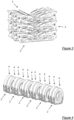
- FIGs 1 to 4 are views of a rack 2 for carrying a pair of spaced apart wheels 4 in an upright position according to a preferred embodiment of the present invention.
- the rack 2 has a frame having a base 6 and two pairs of arms 8, the arms 8 of each pair being pivotally attached to opposite sides of the base 6 such that the arms 8 can be pivoted between an open configuration and a folded configuration as illustrated in Figures 2 and 3 .
- each pair of arms 8 is arranged to extend generally upwardly so as to receive an upright wheel 4 therebetween.
- the arms 8 are foldable inwardly onto the base 6 so as to provide a compact configuration for storage.
- the rack 2 is configured to carry a dual set of wheels 4, such as those used on opposing sides of each axle of heavy vehicles, the wheels 4 being carried in the arms 8 in an upright spaced-apart configuration which is substantially the same as the spaced-apart configuration when the dual set of wheels 4 is installed on the axle.
- the rack 2 is configured to carry the wheels 4 such that the stud hole alignment of the wheels is maintained from removal to storage to re-installation. This is of particular advantage when wishing to re-install the wheels 4 on the axle after the brake assemblies have been serviced and inspected, which will be discussed in detail further in the disclosure.
- the tyres 10 of the wheels 4 are supported on lower portions of the arms 8 of the rack 2 in the open configuration which effect pivoting of the arms 8 inwardly such that upper portions of the arms 8 clamp about opposing sides of the rims of the tyres 10 of the upright wheels 4.
- the weight of the wheels 4 assist in holding the wheels 4 in a stable upright position in which movement is restricted which avoids the risk of rolling or falling thus preventing injury.
- each arm 8 has a width substantially the width of the wheel 4 for which it is adapted to carry and further each arm 8 has a pair of support portions 12 to provide additional support to the wheels 4 when they are received in the rack 2.
- the support portions 12, as illustrated in Figures 1 and 2 are in the form of wing-like flanges which extend on opposite sides of the upper portions of each arm 8, and which are configured to receive the rim edges of each respective tyre 10.
- the support portions 12 are directed inwardly at an angle which is substantially the angle of the edge of the tyre rim, for example at 25° for heavy vehicle tyres.
- the inwardly facing parts of the arms 8 and support portions 12 conform substantially to the profile of the tyre rim to ensure that the wheels 4 are held in the rack 2 securely and stably.
- the arms 8 on each side of the frame are coupled together so that they move in tandem and are spaced apart in a substantially similar configuration to the wheels 4 on the axle.
- the coupling is in the form of a bar 14 extending across both arms 8, this bar 14 also permits access to the rack 2 for engagement to an apparatus 16 for supporting and moving the rack 2 which will be discussed in more detail further in this disclosure.
- the rack 2 holds the pair of wheels 4 stably and upright so that they can be stored easily and efficiently without risk of rolling.
- all the wheels 4 from a Double B trailer can be received on respective racks 2 to advantageously store them all in a neat and tidy manner avoiding risk of injury to service technicians.
- the rack 2 illustrated in the Figures carries a pair of wheels for removal and installation of wheels 4 from a heavy vehicle trailer, the rack can easily be configured to hold a single wheel 4, such as those used in non-commercial vehicles in a similar manner.
- Figure 3 is a perspective view of three such racks 2 of Figure 1 in a folded configuration.
- the arms 8 are folded inwardly to form a compact configuration for storage which is reduced in width and in which form they are stackable.
- the folded rack 2 is stackable onto another such folded rack 2 and so forth so as to form a vertical stack of Figure 3 .
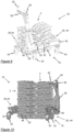
- Figures 5 to 11 are perspective views of a system 18 having an apparatus 16 for supporting a rack 2 as described hereinbefore.
- the apparatus 16 is configured to be expandable and contractible between an expanded configuration where the apparatus 16 can support the engaged rack 2 carrying the wheels 4 in the open configuration as illustrated in Figure 6 and a contracted configuration where the apparatus 16 can support folded racks 2 in a vertical stack as illustrated in Figures 9 and 10 .
- the apparatus 16 is also configured to be positionable relative to the axle of the heavy vehicle and movable away from the heavy vehicle to facilitate removal of the stacked racks 2 or rack 2 carrying wheels and is exemplified in the Figures 5 to 11 as a trolley.
- the apparatus 16 has a rack engagement assembly 20 configured to engage accessible portions 22, 24 on opposing sides of the rack and to support the engaged rack 2 while it is being moved between one position to another.
- the expanded apparatus 16 is configured to support the engaged open rack 2 carrying a pair of wheels 4 to move it between an in-situ position and a removed position to facilitate removal and installation of the wheels 4.
- the contracted apparatus 16 is configured to support the lower-most engaged folded rack 2 of a vertical stack, and any folded rack(s) 2 supported thereon, for transport and storage thereof.
- the apparatus 16 also has a lifting assembly 26 for raising and lowering the rack 2 in the open configuration or in a folded configuration, when so engaged, to facilitate servicing, storage and transport.
- the lifting assembly 26 In the expanded configuration, the lifting assembly 26 is configured to raise and lower the rack engagement assembly 20, and the engaged rack 2 and wheels 4.
- the lifting assembly 26 In the contracted configuration, the lifting assembly 26 is configured to raise and lower the rack engagement assembly 20 to raise and lower an engaged folded rack 2 along with any folded racks 2 supported thereon.
- the apparatus 16 in the expanded configuration facilitates easy and efficient support of a rack 2 carrying a pair of wheels without requiring heavy lifting and which can be moved easily to and from a heavy vehicle which reduces the risk of injury, and further reduces the costs and time take to remove and re-install the wheels 4.
- the apparatus 16, in the contracted configuration is configured for transport of a stack of folded racks 2 between a storage location and the heavy vehicle.
- the apparatus 16 has a generally U-shaped horizontal frame having spaced-apart opposed feet 28 extending from ends of a rear portion 30, the feet 28 forming an opening at one side to permit a rack 2 carrying a pair of wheels or a stack of racks 2 to be received therein, depending on whether the apparatus 16 is in the expanded or contracted configuration.
- the rear portion 30 includes a shaft which can be received in a correspondingly shaped sleeve so as to form a telescopic arrangement to widen or narrow the frame and thereby increase or decrease the space between the feet 28.
- a handle 32 actuates a manual crank arrangement (not shown) effecting the widening or narrowing of the frame.
- the handle 32 is rotatable to actuate the manual crank arrangement between a first position where the apparatus 16 is wider as illustrated in Figures 5 and 6 , and a second position, where the handle is parallel to but oriented in an opposite direction to the first position, where the apparatus 16 is narrower as illustrated in Figures 9 and 10 .
- the apparatus 16 can be expanded and contracted in width from about 1250mm to about 1100 mm wide.
- the frame is supported from the ground by four rollers 34 in the form of swivel castors such that the apparatus 16 is positionable, when in either configuration, relative to the heavy vehicle and movable away from heavy vehicle to remove or install wheels 4, or store or move racks 2.
- rollers 34 are associated with the rear portion 30 of the frame, and one roller 34 is associated with the end portion of each foot 28.
- a locking arrangement (not shown) may be provided to lock the wheels 4 if necessary for facilitating servicing.
- the apparatus 16 has a generally horizontal handle 36 supported at one end from the frame by an upright member 38 in the form of a generally vertical post.
- the handle 36 is rotatable about the upright member 38 between adjacent sides of the frame to assist a user in moving the apparatus 16 from that frame side.
- the handle 36 is positioned above and parallel to one of the feet 28 and is thus in a position so that a user can easily move the apparatus through a workshop due to its reduced width.
- the handle 36 is rotatable into a position parallel to the rear portion 30 of the frame, and is therefore in an optimal position for a user to move the apparatus 16 forwards and backwards such that the rack(s) 2, are easily receivable within the opening to remove and install wheels 4 relative to the axle.
- the apparatus 16 has a locking arrangement 40 which prevents rotation of the handle 36 for ease of use.
- the handle 16 also has an angled portion 42 at an end opposite to the vertical post for ergonomic purposes.
- the lifting assembly 26 includes two lifting devices 44, one device for lifting each foot 28 of the frame.
- Each lifting device 44 has foldable elongate members in a parallelogram type linkage having upper and lower portions actuated by a hydraulic cylinder 46 therebetween, and where the lower portions are pivotally attached to a respective foot 28 of the frame.
- a hydraulically-powered system in the form of a main supply cylinder drives the matching hydraulic cylinders 46 associated with the feet 28 together in a master-slave type arrangement, effecting folding and unfolding of the elongate members on each foot 28 together and thus raising and lowering the rack engagement assembly 20.
- the lifting assembly 26 can be actuated by other systems such as a pneumatic cylinder or electrically operated power screw.
- the main cylinder (not shown) is actuated by a ratchet system (not shown) operable by a handle 50.
- the ratchet system operates with a 700:1 ratio such that the engaged rack 2 can be raised in small increments necessary for accurate height adjustment, for example when vertically positioning the carried wheels 4 for removal or reinstalment on the vehicle.
- the lifting assembly is configured 26 to be able to raise the rack engagement assembly 20 to a maximum of about 100 mm, although when the apparatus 16 is generally used for removing or re-installing the wheels 4, the applicant expects that only 10 to 15mm of lift will be required.
- the lifting assembly exhibits a substantially vertical lift over the 10 to 15 mm of lift so that the wheels 4 can be lifted off the axle without catching on the stud.
- a bleed valve (not shown) is also provided to lower the engaged rack 2 and may be operable by a foot pedal or handle (not shown) on the apparatus 16.
- the bleed valve has a retarder (not shown) to ensure the lowering of the rack engagement assembly 20 and engaged rack 2 is slow and controlled.
- handles 32,36, 50 for operation of the apparatus discussed above may be conveniently located and/or arranged to be operated by foot, as well as by hand, and thus may be in the form of a foot pedal.
- the rack engagement assembly 20 has a pair of engagement members 48, each engagement member 48 in the form of elongate plates carried by a respective foot 28 of the frame and being configured to engage with accessible portions 22, 24 of the rack 2, depending on the configurations of the apparatus 16 and rack 2. As illustrated in Figures 5 to 8 , when the apparatus 16 is in the expanded configuration, upper portions of the engagement members 48 are configured to engage with first accessible portions 22 of the rack 2 in the open configuration carrying the wheels 4. In a similar manner, when apparatus 16 is in the contracted configuration, lower portions of the engagement members 48 are configured to engage with second accessible portions 24 of the rack(s) 2 in the folded configuration.
- each engagement member 48 is in the form of an upright elongate flange while the first accessible portion 22 on each side of the rack 2 in the form of a downwardly facing open end of a channel.
- the engagement members 48 can be raised by the lifting assembly 26 such that the upright flanges are received in the respective open channel ends.
- the channels 22 are formed in the bars 14 connecting the arms 8 on each side of the open rack 2. Therefore, once the open rack 2 is thus so engaged and supported by the rack engagement assembly 20, the apparatus 16 can be moved to and from the heavy vehicle to facilitate removal and re-installation of the wheels 4.
- the rack engagement assembly 20 is engageable with the lower-most folded rack of the vertical stack.
- the lower portions of the engagement members 48 engage with second accessible portions 24 on the folded lower-most rack 2 which are in the form of generally horizontal rods which extend between opposing sides of each arm.
- the lower portions of the engagement members 48 are in the form of finger portions which have upwardly directed flange portions at the lower ends thereby forming cavities, open ends of which face upwardly.
- the engagement assembly 20 can be raised by the lifting assembly 26 such that the rods of each arm 8 can be received in the respective cavities. Therefore, once the engaged lower-most folded rack 2, and any folded rack(s) 2 supported thereon, is thus supported by the rack engagement assembly 20, the apparatus 16 can be moved to and from the heavy vehicle to transport the rack(s) 2 to facilitate removal and installation of the wheels 4.
- the apparatus 16 and racks 2 can be used to facilitate removal of all the wheels 4 from the heavy vehicle before inspection and servicing the heavy brake assembly and then re-installation of all the wheels.
- the apparatus 16 in the contracted configuration engages and supports a vertical stack of folded racks 2 at a storage location.
- the engaged stack of racks 2 is then moved to the heavy vehicle for distribution in preparation for removal of the wheels 4.
- Each rack 2 is unfolded by the technician and positioned under each pair of dual wheels 4.
- the apparatus 16 is then expanded and then the apparatus 16 is positioned such that the open rack 2 is received between the feet 28 of the frame.
- the rack engagement assembly 20 is then raised by operating the lifting assembly 26 to engage and raise the open rack 2 such that the wheels 4 are supported thereon.
- the upper portions of the arms 8 clamp about the tyre rims of the upright wheels 4 to hold the wheels 4 in a stable upright spaced-apart configuration and advantageously maintain the alignment of the stud holes.
- the two sets of arms 8 of the rack 2 are configured to receive the wheels 4 in a spaced-apart configuration which conforms to the arrangement of the wheels 4 on each axle. This facilitates easy removal of the two wheels of each dual set simultaneously.
- each set of dual wheels 4 is kept in a stable and upright position which prevents the wheels from rolling or falling over and reduces the area required for storage of the 24 wheels.
- the stud-hole alignment and spaced-apart configuration of the wheels 4 in each dual set is preserved indefinitely by the rack 2 which facilitates easy re-installation of each dual wheel set 4 onto a respective axle.
- the ease of removal and positioning of the apparatus 16 is facilitated by the ability of the handle 36 to rotate between positions, thereby allowing the apparatus 16 to be moved in different directions depending on the manner in which the apparatus 16 is operated.
- the handle 36 facilitates ease of movement of the apparatus 16 forwards and backwards to move the open rack 2 carrying the wheels 4 relative to the axle or when moving the apparatus 16 to engage the stack of racks 2.
- the handle 36 by rotating the handle 36 to be parallel with a foot 28 of the frame, the reduced width of the apparatus 16 in the direction of travel facilitates ease of handling when transporting the vertical stack of racks 2 or the rack carrying the wheels 2 from a service area to a storage location.
- the wheels 4 can be re-installed using a method which is generally the reverse of the removal procedure discussed above. It will be appreciated that the method described is a mere example, and the apparatus 16 and rack(s) 2 can be used in a variety of ways to facilitate removal and installation of the wheels 4 of the heavy vehicle.
Landscapes
- Engineering & Computer Science (AREA)
- Mechanical Engineering (AREA)
- Life Sciences & Earth Sciences (AREA)
- Geology (AREA)
- Structural Engineering (AREA)
- Handcart (AREA)
Claims (12)
- System zum Abnehmen und Montieren von Rädern (4) an einem schweren Fahrzeug, das Folgendes umfasst:eine Einrichtung (16) und ein Gestell (2) zum Halten eines Rades (4) in einer aufrechten Position;das Gestell (2) hat einen Rahmen mit einer Basis (6) und einem Paar von Armen, wobei jeder Arm (8) an gegenüberliegenden Seiten der Basis (6) schwenkbar befestigt und ferner dazu ausgelegt ist, ein Schwenken in eine offene Auslegung zu ermöglichen, in der die Arme (8) angeordnet sind, sich im Allgemeinen nach oben zu erstrecken, um ein aufrechtes Rad dazwischen aufzunehmen, und in eine zusammengeklappte Auslegung, in der die Arme nach innen auf die Basis (6) klappbar sind;das Einrichtungs (16)-Gestell (2), das dazu ausgelegt ist, in das Gestell (2) einzugreifen, um das Abnehmen und Montieren des Rades (4) an einem schweren Fahrzeug zu erleichtern, wobei die Einrichtung (16) Folgendes umfasst:eine Gestell (2)-Eingriffsanordnung (20), die dazu ausgelegt ist, in zugängliche Abschnitte des Gestells (2) einzugreifen und das Gestell (2) zu stützen, wenn es sich im Eingriff befindet;eine Hebeanordnung (26) zum Anheben und Absenken der Gestell (2)-Eingriffsanordnung (20) und des Gestells (2), wenn es sich im Eingriff der Gestell (2)-Eingriffsanordnung (20) befindet,wobei die Einrichtung (16) dazu ausgelegt ist, relativ zum schweren Fahrzeug positionierbar und vom Fahrzeug weg bewegbar zu sein, um das Abnehmen und Montieren der Räder (4) zu erleichtern; und wobei die Einrichtung (16) zwischen einer ausgeklappten Auslegung, in der die Gestell (2)-Eingriffsanordnung (20) dazu ausgelegt ist, in das Gestell (2) in der offenen Auslegung einzugreifen, und einer eingeklappten Auslegung, in der die Gestell (2)-Eingriffsanordnung (20) dazu ausgelegt ist, in das Gestell (2) in der zusammengeklappten Auslegung einzugreifen, ausklappbar und einklappbar ist;wobei die Einrichtung (16), wenn sie sich in der ausgeklappten Auslegung befindet, mit einem Gestell (2) in der offenen Auslegung in Eingriff gebracht werden kann und wobei die Einrichtung (16), wenn sich das Gestell (2), das mindestens ein Rad (4) trägt, derart im Eingriff befindet, relativ zum schweren Fahrzeug positionierbar und vom Fahrzeug weg bewegbar ist, um das Abnehmen und Montieren des einen oder der mehreren Räder (4) zu erleichtern.
- System (18) nach Anspruch 1, wobei das Gestell (2) jeder Arm einen unteren Abschnitt aufweist, der angeordnet ist, einen unteren Felgenabschnitt eines Reifens des Rades (4) über der Basis (6) zu stützen, derart, dass, wenn das Rad (4) so in der aufrechten Position gestützt ist, die Arme sich nach innen drehen, um obere Abschnitte davon um die gegenüberliegenden Seiten der Felge des Reifens zu klemmen.
- System (18) nach Anspruch 1 oder Anspruch 2, wobei das Gestell (2) auf gegenüberliegenden Seiten von jedem Arm ein Paar von Stützabschnitten aufweist, wobei die Stützabschnitte angeordnet sind, gegenüberliegende Seitenkanten der Reifenfelge aufzunehmen.
- System (18) nach einem der vorhergehenden Ansprüche, wobei das Gestell (2) wobei die Arme eines von zwei Paaren von Armen sind, derart, dass das Gestell (2) dazu ausgelegt ist, ein Paar von aufrechten Rädern (4) in einer parallelen beabstandeten Auslegung aufzunehmen, wobei jedes Rad (4) in eines von jedem Paar von zugehörigen Armen aufnehmbar ist.
- System (18) nach Anspruch 4, wobei das Gestell (2) wo die Arme auf jeder Seite der Basis (6) zusammengekoppelt sind, um in Tandem drehbar zu sein.
- System (18) nach einem der vorhergehenden Ansprüche, wobei die Arme des Gestells (2) in eine zusammengeklappte Auslegung schwenkbar sind, in der die Arme nach innen auf die Basis (6) zusammenklappbar sind, das Gestell (2) in der zusammengeklappten Auslegung auf ein anderes derart zusammengeklapptes Gestell (2) stapelbar ist, um einen vertikalen Stapel zu bilden.
- System (18) nach Anspruch 1, wobei die Hebeanordnung (26) ein Paar von Hebevorrichtungen (44) aufweist, wobei jede Hebevorrichtung mindestens ein verlinktes zusammenklappbares Stützelement umfasst, das dazu ausgelegt ist, für eine Bewegung in der vertikalen Ebene angetrieben zu werden, wobei ein oberer Abschnitt des einen oder der mehreren Stützelemente mit der Gestell (2)-Eingriffsanordnung (20) verknüpft ist und ein unterer Abschnitt des einen oder der mehreren Stützelemente mit der Einrichtung (16) verknüpft ist und wobei das eine oder die mehreren zusammenklappbaren Stützelemente ausklappbar und zurückziehbar sind, um die Gestell (2)-Eingriffsanordnung (20) anzuheben und abzusenken.
- System (18) nach Anspruch 1 oder 7, wobei die Einrichtung (16) einen Rahmen mit beabstandeten Füßen (28) aufweist, wobei das Gestell (2) in den von den Füßen (28) definierten Raum aufnehmbar ist.
- System (18) nach Anspruch 8, wobei die Einrichtung (16) ein hydraulisch angetriebenes System aufweist, das ein Paar von Hydraulikzylindern (46) beinhaltet, wobei jeder Zylinder (46) dem Antreiben des einen oder der mehreren Stützelemente, die mit einem jeweiligen Fuß verknüpft sind, dient und das hydraulisch angetriebene System zum Antreiben des vorgenannten Paares von Hydraulikzylindern wahlweise einen Haupthydraulikzylinder (46) aufweist.
- System (18) nach Anspruch 1 oder 7 bis 9, wobei die Einrichtung (16), wenn sie sich in der eingeklappten Auslegung befindet, die Gestell (2)-Eingriffsanordnung (20) dazu ausgelegt ist, in einem vertikalen Stapel von Gestellen (2) in das unterste Gestell (2) einzugreifen, wobei sich jedes Gestell (2) in der zusammengeklappten Auslegung befindet.
- System (18) nach Anspruch 8 oder einem der Ansprüche 9 oder 10, wobei die Einrichtung (16) einen im Allgemeinen horizontalen Griff (36) aufweist, der über dem Rahmen von einem aufrechten Element (38) gestützt wird, wobei der Griff zwischen benachbarten Seiten des Rahmens um das aufrechte Element (38) drehbar ist, um einen Benutzer beim Bewegen der Einrichtung (16) von dieser Rahmenseite zu unterstützen.
- Verfahren zum Abnehmen und/oder Montieren von Rädern (4) an einem Fahrzeug unter Verwendung des Systems von Anspruch 1 bis Anspruch 11, das die folgenden Schritte umfasst:Anheben einer Achse des Fahrzeugs, derart, dass das Rad (4) von der Achse herunterhängt;Positionieren des Gestells (2) in einer offenen Auslegung unter dem Rad (4);Eingreifen der Gestell (2)-Eingriffsanordnung (20) der Einrichtung (16) in das Gestell (2) in der offenen Auslegung;Anheben der Einrichtung (16), um in das Gestell (2) und das in das Gestell (2) aufgenommene Rad (4) einzugreifen; undAbnehmen des im Eingriff befindlichen Gestells (2) vom Fahrzeug undwahlweise wobei das Fahrzeug ein schweres Fahrzeug ist und das Rad (4) eines von einem Paar von Rädern (4) ist, die auf einer Achse des schweren Fahrzeugs getragen werden, wobei die Räder im Gestell (2) in einer beabstandeten Auslegung aufnehmbar sind.
Applications Claiming Priority (2)
| Application Number | Priority Date | Filing Date | Title |
|---|---|---|---|
| AU2017904000A AU2017904000A0 (en) | 2017-10-04 | A rack and apparatus for supporting wheels | |
| PCT/AU2018/051073 WO2019068143A1 (en) | 2017-10-04 | 2018-10-03 | SUPPORT AND APPARATUS FOR SUPPORTING WHEELS |
Publications (4)
| Publication Number | Publication Date |
|---|---|
| EP3707009A1 EP3707009A1 (de) | 2020-09-16 |
| EP3707009A4 EP3707009A4 (de) | 2021-09-01 |
| EP3707009B1 true EP3707009B1 (de) | 2025-06-04 |
| EP3707009C0 EP3707009C0 (de) | 2025-06-04 |
Family
ID=65994175
Family Applications (1)
| Application Number | Title | Priority Date | Filing Date |
|---|---|---|---|
| EP18863909.0A Active EP3707009B1 (de) | 2017-10-04 | 2018-10-03 | Gestell und vorrichtung zum tragen von rädern |
Country Status (5)
| Country | Link |
|---|---|
| US (2) | US11292293B2 (de) |
| EP (1) | EP3707009B1 (de) |
| AU (1) | AU2018344764B2 (de) |
| CA (1) | CA3078402A1 (de) |
| WO (1) | WO2019068143A1 (de) |
Families Citing this family (8)
| Publication number | Priority date | Publication date | Assignee | Title |
|---|---|---|---|---|
| AU2018344764B2 (en) | 2017-10-04 | 2025-03-06 | Workplace Maintenance Solutions Pty Ltd | A rack and apparatus for supporting wheels |
| FR3099453B1 (fr) * | 2019-08-01 | 2022-12-23 | A C E Ingenierie | Support de manutention, système et procédé de manutention mettant en œuvre un tel support |
| US11478089B2 (en) * | 2019-08-17 | 2022-10-25 | Hosein Niroumandrad | Connection apparatus for providing an inclined display of a vehicle |
| CN110667307B (zh) * | 2019-09-03 | 2021-02-09 | 苏州巴涛信息科技有限公司 | 一种重型卡车轮胎拆卸装置 |
| CA3119375A1 (en) * | 2021-05-21 | 2022-11-21 | Canadian Tire Corporation, Limited | Wheel storage apparatus and kit |
| CN113247830B (zh) * | 2021-05-25 | 2022-07-01 | 青岛现代海麟重工有限公司 | 一种智能检测防倾倒托盘叉车 |
| KR102694003B1 (ko) * | 2021-11-30 | 2024-09-12 | 주식회사 제일자동차정비공구 | 타이어 리프트 |
| US12338110B2 (en) * | 2022-11-10 | 2025-06-24 | Juan Martin, Jr. | Truck wheel lifting cart |
Family Cites Families (19)
| Publication number | Priority date | Publication date | Assignee | Title |
|---|---|---|---|---|
| US2380415A (en) * | 1943-11-10 | 1945-07-31 | Earl R Carruthers | Dual wheel and tire lift |
| US2956763A (en) * | 1957-03-08 | 1960-10-18 | Clark Equipment Co | Collapsible pallet |
| US3850295A (en) * | 1971-10-12 | 1974-11-26 | B Black | Tire shipping and storage structure |
| US3812974A (en) * | 1972-10-06 | 1974-05-28 | R Sylvester | Green tire support |
| US4042139A (en) | 1975-05-09 | 1977-08-16 | Pernsteiner Harold R | Vehicle wheel-removing and handling device |
| US4350470A (en) * | 1980-06-09 | 1982-09-21 | Hernando Murillo | Wheel truck |
| DE3440042A1 (de) * | 1984-11-02 | 1986-05-07 | Norbert 3533 Willebadessen Bernholz | Transportwagen und wechselwagen fuer raeder |
| US6581785B1 (en) * | 2002-01-15 | 2003-06-24 | Albert Screenprint, Inc. | Adjustable tire stand |
| JP3979638B2 (ja) * | 2002-07-05 | 2007-09-19 | 株式会社リコー | 物品運搬保管装置 |
| US7097406B1 (en) * | 2002-11-16 | 2006-08-29 | Wang Gang | Wheel skate |
| US7677582B2 (en) * | 2006-05-18 | 2010-03-16 | Justoy Pty Ltd. | Vehicular component apparatus |
| WO2010000018A1 (en) | 2008-06-30 | 2010-01-07 | Wilhelmsen Manufacturing Australia Pty Limited | Aircraft tyre stillage |
| AU2009225278B2 (en) * | 2008-10-10 | 2014-08-14 | Prowse Holdings Pty Ltd | Wheel Handling Apparatus |
| SE534549C2 (sv) * | 2009-12-22 | 2011-09-27 | Lars Askling | Hjullyft |
| CA2813342C (en) * | 2010-09-29 | 2019-04-30 | Dealer Tire, Llc | Portable on-tread tire rack |
| WO2015042658A1 (en) * | 2013-09-24 | 2015-04-02 | Wilhelmsen Manufacturing Australia Pty Ltd | System and method for replacement of aircraft wheels |
| US20150290972A1 (en) * | 2014-04-11 | 2015-10-15 | Vision Global Technology, Inc. | Wheel Lift and Transport Device |
| US9580236B1 (en) * | 2015-01-16 | 2017-02-28 | Mobile Shelter Systems As | Storage and transport container |
| AU2018344764B2 (en) | 2017-10-04 | 2025-03-06 | Workplace Maintenance Solutions Pty Ltd | A rack and apparatus for supporting wheels |
-
2018
- 2018-10-03 AU AU2018344764A patent/AU2018344764B2/en active Active
- 2018-10-03 US US16/753,473 patent/US11292293B2/en active Active
- 2018-10-03 WO PCT/AU2018/051073 patent/WO2019068143A1/en not_active Ceased
- 2018-10-03 EP EP18863909.0A patent/EP3707009B1/de active Active
- 2018-10-03 CA CA3078402A patent/CA3078402A1/en active Pending
-
2022
- 2022-03-01 US US17/653,112 patent/US11787233B2/en active Active
Also Published As
| Publication number | Publication date |
|---|---|
| US11292293B2 (en) | 2022-04-05 |
| EP3707009C0 (de) | 2025-06-04 |
| EP3707009A1 (de) | 2020-09-16 |
| EP3707009A4 (de) | 2021-09-01 |
| US20220266629A1 (en) | 2022-08-25 |
| US20200290399A1 (en) | 2020-09-17 |
| US11787233B2 (en) | 2023-10-17 |
| AU2018344764B2 (en) | 2025-03-06 |
| AU2018344764A1 (en) | 2020-05-21 |
| WO2019068143A1 (en) | 2019-04-11 |
| CA3078402A1 (en) | 2019-04-11 |
Similar Documents
| Publication | Publication Date | Title |
|---|---|---|
| EP3707009B1 (de) | Gestell und vorrichtung zum tragen von rädern | |
| US3830387A (en) | Vehicle wheel handling apparatus | |
| US10974778B2 (en) | Track mounting tool | |
| US12071991B2 (en) | Apparatus for supporting a heavy vehicle brake assembly | |
| US3850321A (en) | Wheel dolly | |
| US9771990B2 (en) | Brake component handling apparatus | |
| US20150290972A1 (en) | Wheel Lift and Transport Device | |
| US20170174487A1 (en) | Transformable Table | |
| US20040021280A1 (en) | Method and apparatus for moving shelf units including moving shelf units arranged in a gondola having the shelves fully loaded with goods | |
| US20130140144A1 (en) | Conveyor Roller Support Arrangement | |
| US20180180118A1 (en) | Trolley for supporting a heavy vehicle brake assembly | |
| US9045000B1 (en) | Tire changing apparatus | |
| US2730166A (en) | Mobile trolley mounted tire removing machine | |
| EP0125551B1 (de) | Tragbarer, gelenkiger Hubwagen zum Erleichtern des Radwechselns von Reisebussen, Lastkraftwagen, Schleppern und ähnlichen Kraftfahrzeugen | |
| US7942620B2 (en) | Tire handling apparatus | |
| US20220258533A1 (en) | Vehicle Tire/Wheel Changing Device | |
| JPH01132401A (ja) | タイヤ運搬装置 | |
| US12012319B2 (en) | Tire and wheel lift assistance assembly and method | |
| AU2017258965A1 (en) | Lifting and support device | |
| US20250002310A1 (en) | Wheel Component Handling Device | |
| DK177607B1 (en) | Wheel lifting device for handling of tires | |
| CA2527552C (en) | Tire handling apparatus | |
| CA2575525A1 (en) | Conveyor apparatus for vehicle wheel removal |
Legal Events
| Date | Code | Title | Description |
|---|---|---|---|
| STAA | Information on the status of an ep patent application or granted ep patent |
Free format text: STATUS: THE INTERNATIONAL PUBLICATION HAS BEEN MADE |
|
| PUAI | Public reference made under article 153(3) epc to a published international application that has entered the european phase |
Free format text: ORIGINAL CODE: 0009012 |
|
| STAA | Information on the status of an ep patent application or granted ep patent |
Free format text: STATUS: REQUEST FOR EXAMINATION WAS MADE |
|
| 17P | Request for examination filed |
Effective date: 20200806 |
|
| AK | Designated contracting states |
Kind code of ref document: A1 Designated state(s): AL AT BE BG CH CY CZ DE DK EE ES FI FR GB GR HR HU IE IS IT LI LT LU LV MC MK MT NL NO PL PT RO RS SE SI SK SM TR |
|
| AX | Request for extension of the european patent |
Extension state: BA ME |
|
| DAV | Request for validation of the european patent (deleted) | ||
| DAX | Request for extension of the european patent (deleted) | ||
| A4 | Supplementary search report drawn up and despatched |
Effective date: 20210802 |
|
| RIC1 | Information provided on ipc code assigned before grant |
Ipc: B60B 30/10 20060101AFI20210727BHEP Ipc: B60B 29/00 20060101ALI20210727BHEP Ipc: B60P 3/077 20060101ALI20210727BHEP |
|
| STAA | Information on the status of an ep patent application or granted ep patent |
Free format text: STATUS: EXAMINATION IS IN PROGRESS |
|
| 17Q | First examination report despatched |
Effective date: 20230322 |
|
| GRAP | Despatch of communication of intention to grant a patent |
Free format text: ORIGINAL CODE: EPIDOSNIGR1 |
|
| STAA | Information on the status of an ep patent application or granted ep patent |
Free format text: STATUS: GRANT OF PATENT IS INTENDED |
|
| INTG | Intention to grant announced |
Effective date: 20240910 |
|
| GRAS | Grant fee paid |
Free format text: ORIGINAL CODE: EPIDOSNIGR3 |
|
| GRAA | (expected) grant |
Free format text: ORIGINAL CODE: 0009210 |
|
| STAA | Information on the status of an ep patent application or granted ep patent |
Free format text: STATUS: THE PATENT HAS BEEN GRANTED |
|
| AK | Designated contracting states |
Kind code of ref document: B1 Designated state(s): AL AT BE BG CH CY CZ DE DK EE ES FI FR GB GR HR HU IE IS IT LI LT LU LV MC MK MT NL NO PL PT RO RS SE SI SK SM TR |
|
| REG | Reference to a national code |
Ref country code: GB Ref legal event code: FG4D |
|
| REG | Reference to a national code |
Ref country code: CH Ref legal event code: EP |
|
| REG | Reference to a national code |
Ref country code: DE Ref legal event code: R096 Ref document number: 602018082466 Country of ref document: DE |
|
| REG | Reference to a national code |
Ref country code: IE Ref legal event code: FG4D |
|
| U01 | Request for unitary effect filed |
Effective date: 20250703 |
|
| U07 | Unitary effect registered |
Designated state(s): AT BE BG DE DK EE FI FR IT LT LU LV MT NL PT RO SE SI Effective date: 20250710 |
|
| U20 | Renewal fee for the european patent with unitary effect paid |
Year of fee payment: 8 Effective date: 20250902 |
|
| PG25 | Lapsed in a contracting state [announced via postgrant information from national office to epo] |
Ref country code: ES Free format text: LAPSE BECAUSE OF FAILURE TO SUBMIT A TRANSLATION OF THE DESCRIPTION OR TO PAY THE FEE WITHIN THE PRESCRIBED TIME-LIMIT Effective date: 20250604 |
|
| PG25 | Lapsed in a contracting state [announced via postgrant information from national office to epo] |
Ref country code: GR Free format text: LAPSE BECAUSE OF FAILURE TO SUBMIT A TRANSLATION OF THE DESCRIPTION OR TO PAY THE FEE WITHIN THE PRESCRIBED TIME-LIMIT Effective date: 20250905 Ref country code: NO Free format text: LAPSE BECAUSE OF FAILURE TO SUBMIT A TRANSLATION OF THE DESCRIPTION OR TO PAY THE FEE WITHIN THE PRESCRIBED TIME-LIMIT Effective date: 20250904 |
|
| PG25 | Lapsed in a contracting state [announced via postgrant information from national office to epo] |
Ref country code: PL Free format text: LAPSE BECAUSE OF FAILURE TO SUBMIT A TRANSLATION OF THE DESCRIPTION OR TO PAY THE FEE WITHIN THE PRESCRIBED TIME-LIMIT Effective date: 20250604 |
|
| PGFP | Annual fee paid to national office [announced via postgrant information from national office to epo] |
Ref country code: GB Payment date: 20250831 Year of fee payment: 8 |
|
| PG25 | Lapsed in a contracting state [announced via postgrant information from national office to epo] |
Ref country code: HR Free format text: LAPSE BECAUSE OF FAILURE TO SUBMIT A TRANSLATION OF THE DESCRIPTION OR TO PAY THE FEE WITHIN THE PRESCRIBED TIME-LIMIT Effective date: 20250604 |
|
| PG25 | Lapsed in a contracting state [announced via postgrant information from national office to epo] |
Ref country code: RS Free format text: LAPSE BECAUSE OF FAILURE TO SUBMIT A TRANSLATION OF THE DESCRIPTION OR TO PAY THE FEE WITHIN THE PRESCRIBED TIME-LIMIT Effective date: 20250904 |