EP3706330B1 - Optisches unterwasserkommunikationssystem - Google Patents
Optisches unterwasserkommunikationssystem Download PDFInfo
- Publication number
- EP3706330B1 EP3706330B1 EP18872584.0A EP18872584A EP3706330B1 EP 3706330 B1 EP3706330 B1 EP 3706330B1 EP 18872584 A EP18872584 A EP 18872584A EP 3706330 B1 EP3706330 B1 EP 3706330B1
- Authority
- EP
- European Patent Office
- Prior art keywords
- optical
- transmission apparatus
- optical transmission
- submarine
- signal
- Prior art date
- Legal status (The legal status is an assumption and is not a legal conclusion. Google has not performed a legal analysis and makes no representation as to the accuracy of the status listed.)
- Active
Links
Images





Classifications
-
- H—ELECTRICITY
- H04—ELECTRIC COMMUNICATION TECHNIQUE
- H04B—TRANSMISSION
- H04B10/00—Transmission systems employing electromagnetic waves other than radio-waves, e.g. infrared, visible or ultraviolet light, or employing corpuscular radiation, e.g. quantum communication
- H04B10/07—Arrangements for monitoring or testing transmission systems; Arrangements for fault measurement of transmission systems
- H04B10/075—Arrangements for monitoring or testing transmission systems; Arrangements for fault measurement of transmission systems using an in-service signal
- H04B10/077—Arrangements for monitoring or testing transmission systems; Arrangements for fault measurement of transmission systems using an in-service signal using a supervisory or additional signal
- H04B10/0771—Fault location on the transmission path
-
- H—ELECTRICITY
- H04—ELECTRIC COMMUNICATION TECHNIQUE
- H04B—TRANSMISSION
- H04B10/00—Transmission systems employing electromagnetic waves other than radio-waves, e.g. infrared, visible or ultraviolet light, or employing corpuscular radiation, e.g. quantum communication
- H04B10/80—Optical aspects relating to the use of optical transmission for specific applications, not provided for in groups H04B10/03 - H04B10/70, e.g. optical power feeding or optical transmission through water
-
- H—ELECTRICITY
- H04—ELECTRIC COMMUNICATION TECHNIQUE
- H04B—TRANSMISSION
- H04B10/00—Transmission systems employing electromagnetic waves other than radio-waves, e.g. infrared, visible or ultraviolet light, or employing corpuscular radiation, e.g. quantum communication
- H04B10/03—Arrangements for fault recovery
-
- H—ELECTRICITY
- H04—ELECTRIC COMMUNICATION TECHNIQUE
- H04B—TRANSMISSION
- H04B10/00—Transmission systems employing electromagnetic waves other than radio-waves, e.g. infrared, visible or ultraviolet light, or employing corpuscular radiation, e.g. quantum communication
- H04B10/25—Arrangements specific to fibre transmission
-
- H—ELECTRICITY
- H04—ELECTRIC COMMUNICATION TECHNIQUE
- H04Q—SELECTING
- H04Q11/00—Selecting arrangements for multiplex systems
- H04Q11/0001—Selecting arrangements for multiplex systems using optical switching
- H04Q11/0005—Switch and router aspects
Definitions
- the present disclosure relates to a submarine optical communication system.
- a submarine optical communication system that enables optical communication by connecting base stations on land via a submarine cable is being widely used.
- a submarine relay apparatus that amplifies an attenuation of a transmission signal, a submarine branching apparatus that enables optical communication among three or more base stations disposed on land, etc. are inserted in the submarine cable.
- the submarine branching apparatus is inserted inbetween a submarine cable (a trunk path) that connects two trunk stations, and a submarine cable that configures a branch path branched from the submarine branching apparatus is connected to a branch station.
- a submarine cable a trunk path
- a submarine cable that configures a branch path branched from the submarine branching apparatus is connected to a branch station.
- Patent Literature 1 a system capable of handling failures that occur in the paths through which an optical signal is transmitted.
- power is supplied to a submarine branching apparatus from a branch terminal (i.e., a branch station) through a branch path.
- a branch terminal i.e., a branch station
- an optical switch inside the submarine branching apparatus is switched so as to switch the output destination of the optical signal transmitted from one of the trunk stations from the branch path to the trunk path.
- WO 2016/147610 A1 relates to an extended branch device provided with: a first branch unit provided with a first port connected to a first terminal station, a second port connected to a second terminal station, a third port, a fourth port, and a switch for connecting the first port to the second or third port and connecting the second port to the fourth port; and a first separation unit provided with a fifth port connected to the third port, a sixth port connected to the fourth port, and a seventh port connected to a third terminal station, the first separation unit outputting, from the sixth port, an optical signal having a first wavelength among the optical signals inputted from the fifth port, and outputting, from the seventh port, an optical signal having a second wavelength among the optical signals inputted from the fifth port.
- Patent Literature 1 Japanese Patent No. 5892950
- the terminal (station) gives an instruction to the submarine branching apparatus to switch the path, however, when the branch station detects a failure in the branch path, it is not possible for the terminal (station) to give an instruction to the submarine branching apparatus to switch the path through the branch path.
- the present disclosure has been made in view of the matters mentioned above and has an object to detect a failure in a branch path between a submarine branching apparatus and an optical transmission apparatus by the optical transmission apparatus and to switch a transmission path of an optical signal in accordance with the result of the detection.
- a submarine optical communication system includes: a first optical transmission apparatus configured to output a first optical signal; a second optical transmission apparatus; a third optical transmission apparatus configured to output an optical signal and a monitoring signal; and a submarine branching apparatus including a first return unit configured to return the monitoring signal received from the third optical transmission apparatus and configured to switch an output destination of the first optical signal received from the first optical transmission apparatus to the second optical transmission apparatus or the third optical transmission apparatus, in which the third optical transmission apparatus is further configured to detect the monitoring signal returned from the first return unit and notify the first optical transmission apparatus of a result of the detection, and the first optical transmission apparatus is further configured to instruct the submarine branching apparatus to switch the output destination of the first optical signal in accordance with the notification.
- a failure in a branch path between a submarine branching apparatus and an optical transmission apparatus is detected by the optical transmission apparatus and a transmission path of an optical signal is switched in accordance with the result of the detection.
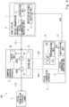
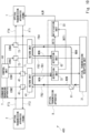
- FIG. 1 is a diagram showing a basic configuration of the submarine optical communication system 100 according to the first example embodiment.
- the submarine optical communication system 100 includes optical transmission apparatuses 1 to 3 and a submarine branching apparatus 4. Note that here, the optical transmission apparatuses 1 to 3 are also referred to as the first to third optical transmission apparatuses, respectively.
- Each of the optical transmission apparatuses 1 and 2 is provided within a trunk station.
- the optical transmission apparatus 1 and the submarine branching apparatus 4 are connected with each other by an optical fiber FT1 incorporated within the submarine cable.
- the optical transmission apparatus 2 and the submarine branching apparatus 4 are connected with each other by an optical fiber FT2 incorporated within the submarine cable.
- a trunk path TL to which a main signal that is an optical signal is transmitted is configured of the optical transmission apparatus 1, the optical transmission apparatus 2, the submarine branching apparatus 4, and the optical fibers FT1 and FT2.
- the optical transmission apparatus 3 is provided within a branch station.
- the optical transmission apparatus 3 and the submarine branching apparatus 4 are connected with each other by an optical fiber FB1 (also referred to as a first optical fiber) for downlink communication and an optical fiber FB2 (also referred to as a second optical fiber) for uplink communication that are incorporated in the submarine cable.
- a branch path is configured of the optical transmission apparatus 3, the submarine branching apparatus 4, and the optical fibers FB1 and FB2.
- FIG. 2 is a diagram showing the submarine optical communication system 100 according to the first example embodiment.
- the optical transmission apparatuses 1 and 2 are installed inside a trunk station T1 and a trunk station T2, respectively.
- the optical transmission apparatus 3 is installed inside a branch station B1.
- the optical transmission apparatus 1 installed in the trunk station T1 includes an optical transmission/reception unit 11, a notification signal reception unit 12, and an instruction unit 13.
- the optical transmission/reception unit 11 outputs a main signal (also referred to as a first optical signal) to the submarine branching apparatus 4 as well as an instruction signal INS for instructing switching of a transmission path of the main signal in accordance with a request from the instruction unit 13 to the submarine branching apparatus 4. Further, the optical transmission/reception unit 11 can receive the optical signal.
- a main signal also referred to as a first optical signal
- an instruction signal INS for instructing switching of a transmission path of the main signal in accordance with a request from the instruction unit 13 to the submarine branching apparatus 4. Further, the optical transmission/reception unit 11 can receive the optical signal.
- a wavelength-division multiplexed signal that has been modulated by a modulation technique such as the DP-QPSK (Dual Polarization-Quadrature Phase Shift Keying) is used as the main signal.
- a modulation technique such as the DP-QPSK (Dual Polarization-Quadrature Phase Shift Keying)
- the notification signal reception unit 12 receives a notification signal ALM from the optical transmission apparatus 3 and informs the instruction unit 13 of the result of the notification.
- the notification signal reception unit 12 may be configured of an EMS (Element Management System) provided to the optical transmission apparatus 1.
- the instruction unit 13 refers to the result of the notification received from the notification signal reception unit 12 and when there is a failure in the branch path, instructs the optical transmission/reception unit 11 to output the instruction signal INS for switching the transmission path of the main signal from the branch path to the trunk path.
- the instruction signal INS may be superimposed on the main signal and output to the submarine branching apparatus 4.
- the instruction signal INS may be a signal having a wavelength other than a wavelength used for the main signal. Further, the instruction signal INS may be superimposed on the main signal by performing full-wave modulation (for example, amplitude modulation) of the main signal.
- Fig. 3 shows an example of a configuration of the optical transmission apparatus 1 according to the example embodiment.
- the optical transmission/reception unit 11 may be configured so as to have a plurality of optical transmitters/receivers (transponders) 14 connectable thereto.
- the optical transmitters/receivers 14 are manufactured by various venders and an arbitrary transponder which conforms to various standards may be used.
- the optical transmission/reception unit 11 may be configured of an OCI (Open Cable Interface).
- OCI Open Cable Interface
- the optical signals output from the plurality of optical transmitters/receivers 14 are multiplexed by a multiplexer 11A of the optical transmission/reception part 11 to become a main signal which is output to a multiplexer 11C.
- the instruction unit 13 controls a signal generation unit 11B of the optical transmission/reception unit 11 whereby the instruction signal INS is output from the signal generation unit 11B to the multiplexer 11C.
- the main signal and the instruction signal INS are multiplexed by the multiplexer 11C and output to the optical fiber FT1.
- the optical transmission apparatus 2 installed in the trunk station T2 can receive the main signal output from the optical transmission apparatus 1 and transmitted through the trunk path or the branch path.
- the optical transmission apparatus 2 may include an optical transmission/reception unit that is the same as the optical transmission/reception unit 11 of the optical transmission reception apparatus 1, or may have the same configuration as that of the optical transmission apparatus 1.
- the submarine branching apparatus 4 is an apparatus that is installed at the bottom of the sea for branching an optical signal that is transmitted through the submarine cable laid at the bottom of the sea.
- the submarine branching apparatus 4 includes a return unit 41, optical switches 42 and 43, and a control unit 44.
- the return unit 41 (also referred to as a first return unit) can selectively return a monitoring signal MON output from the optical transmission apparatus 3 to the optical transmission apparatus 3.
- the return unit 41 includes a filer 41A and a coupler 41B.
- the filter 41A is a wavelength filter and selectively separates only a light having a wavelength of the monitoring signal MON. Therefore, the monitoring signal MON output from the optical transmission apparatus 3 to the optical fiber FB2 is selectively separated by the filter 41A, and the separated monitoring signal MON is output to the optical transmission apparatus 3 through the optical fiber FB1 by the coupler 41B.
- the optical switch 42 (also referred to as a first optical switch) can switch an output path (output destination) of the main signal output from the optical transmission apparatus 1 between the branch path (i.e., a path through which the main signal is output to the optical fiber FB1) and the trunk path (i.e., a path through which the main signal is output to the optical switch 43) in accordance with a control signal CON1 provided from the control unit 44.
- branch path i.e., a path through which the main signal is output to the optical fiber FB1
- the trunk path i.e., a path through which the main signal is output to the optical switch 43
- the optical switch 43 (also referred to as a second optical switch) can switch an input path (an input destination) of the received optical signal to the branch path (i.e., a path through which the main signal is received via the optical fiber FB2) or the trunk path (i.e., a path through which the main signal is received from the optical switch 42) in accordance with a control signal CON2 provided from the control unit 44.
- the branch path i.e., a path through which the main signal is received via the optical fiber FB2
- the trunk path i.e., a path through which the main signal is received from the optical switch 42
- the control unit 44 can receive the instruction signal INS input from the optical transmission apparatus 1 and controls switching between the optical switches 42 and 43 in accordance with the instruction signal.
- the branch station B1 provided to the optical transmission apparatus 3 includes an optical transmission/reception unit 31, a detection unit 32, and a notification unit 33.
- the optical transmission/reception unit 31 can receive the main signal output from the optical transmission apparatus 1 via the optical fiber FB1 and the detection unit 32 and can output an optical signal having a prescribed wavelength to the submarine branching apparatus 4 via the optical fiber FB2. Further, the optical transmission/reception unit 31 can output the monitoring signal MON having a prescribed wavelength to the submarine branching apparatus 4 via the optical fiber FB2.
- the monitoring signal MON may be superimposed on the main signal and output to the submarine branching apparatus 4.
- the monitoring signal MON may be a signal having a wavelength other than a wavelength used for the main signal.
- the main signal which is an object of reception by the optical transmission apparatus 3
- a signal of the L-band (1565nm to 1625nm) may be used as the monitoring signal MON.
- the detection unit 32 detects the monitoring signal MON output from the optical transmission/reception unit 31 to the submarine branching apparatus 4 and returned to the optical transmission apparatus 3 from the return unit 41 of the submarine branching apparatus 4 and outputs a detection signal DET that indicates the result of the detection. For example, the detection unit 32 detects an optical intensity of the monitoring signal MON and outputs a signal that indicates the optical intensity as the detection signal DET.
- the detection unit 32 includes, for example, a filter 32A and an optical reception unit 32B.
- the filter 32A is a wavelength filter and selectively separates only a light having a wavelength of the monitoring signal MON and transmits lights having other wavelengths. Therefore, the control signal MON returned from the return unit 41 of the submarine branching apparatus 4 is selectively separated by the filter 32A and the separated monitoring signal MON is detected by the optical reception unit 32B.
- the optical reception unit 32B is configured using, for example, a photodiode, and can generate the detection signal DET by converting the monitoring signal MON into an electric signal.
- the notification unit 33 outputs the notification signal ALM indicating whether or not the monitoring signal MON has been detected to the notification signal reception unit 12 of the optical transmission apparatus 1 in accordance with the detection signal DET.
- the notification unit 33 informs the notification signal reception unit 12 that a failure has occurred in the branch path configured of the optical fibers FB1 and FB2 through the notification signal ALM when the optical intensity of the monitoring signal MON is smaller than a prescribed threshold value.
- the notification unit 33 may be configured as an EMS (Element Management System) provided to the optical transmission apparatus 3.
- the notification signal ALM may be transmitted from the notification unit 33 to the notification signal reception unit 12 of the optical transmission apparatus 1 using either one of the radio communication or the cable communication, or may be transmitted, for example, via a network that is controlled by a UMS (Unified Management System).
- UMS Unified Management System
- Fig. 4 shows the transmission path of the main signal after switching to the trunk path in the submarine optical communication system 100 according to the first example embodiment.
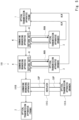
- FIG. 5 is a diagram showing a modified example of the submarine optical communication system according to the first example embodiment.
- a submarine optical communication system 101 shown in Fig. 5 has three submarine branching apparatuses inserted between the optical transmission apparatuses 1 and 2, configuring three branching paths.
- the two submarine branching apparatuses 4 described above and another submarine branching apparatus 101B are inserted on the trunk path from the optical transmission apparatus 1.
- Each of the submarine branching apparatuses 4 is connected to the optical transmission apparatus 3 via the branch path.
- Each of the optical transmission apparatuses 3 can output the notification signal ALM to the optical transmission apparatus 1.
- the submarine branching apparatus 101B is connected to the optical transmission apparatus 101A via the branch path.
- a repeater 101C that amplifies the main signal is inserted in the branch path between the optical transmission apparatus 101A and the submarine branching apparatus 101B.
- power is supplied from the optical transmission apparatus 101A to the submarine branching apparatus 101B and the repeater 101C via a power supply line SUP.
- a failure in the branch path can be detected as described above by having the submarine branching apparatus detect that the power supply has stopped when there is a submarine branching apparatus that has power supplied from the optical transmission apparatus as shown in Fig. 5 .
- the optical transmission apparatus 3 and the submarine branching apparatus 4 can configure a submarine optical communication system along with another optical transmission apparatus of a general configuration and a submarine branching apparatus as shown in Fig. 5 . That is, even when the repeater to which power is supplied from the optical transmission apparatus is not inserted in the branch path, it is possible to detect a failure in the branch path. Further, when the repeater is not inserted in the branch path, by selecting a wavelength at which the main signal transmitted through the branch path can be amplified by Raman amplification as the wavelength of the monitoring signal, it is possible to extend the length of the optical fiber of the branch path.
- FIG. 6 is a diagram showing a modified example of the submarine optical communication system according to the first example embodiment.
- the notification signal reception unit 12 and the notification unit 33 are described to be configurable as an EMS.
- FIG. 6 is a diagram showing a modified example of the submarine optical communication system according to the first example embodiment.
- a submarine optical communication system 102 shown in Fig. 6 includes the optical transmission apparatuses 1 to 3 including the EMS 1A, 2A, and 3A, respectively.
- Each of the EMS 1A, 2A, and 3A can communicate with each other via the cloud network that is controlled by the UMS 102A.
- the optical transmission apparatus 3 can transmit the notification signal ALM to the optical transmission apparatus 1 via the cloud network.
- a SDN (Software Defined Network) controller may be used in place of the UMS and the SDN controller may be set on the cloud.
- the SDN controller can control the transmission path and the wavelength of the optical signal of the submarine optical communication system in accordance with the state of the network or an instruction from an operator. Further, the SDN controller virtually manages the physical network topology and the resource of the submarine optical communication system and can realize sharing of the system by several users or operators.
- the submarine optical communication system can be configured by using not only an exclusive line but also an exclusive or an open cloud network.
- FIG. 7 is a diagram showing a configuration of the submarine optical communication system 200 according to the second example embodiment.
- the submarine optical communication system 200 has a configuration in which the optical transmission apparatus 3 of the submarine optical communication system 100 is replaced by an optical transmission apparatus 5.
- the optical transmission apparatus 5 has a configuration in which a return unit 51 (hereinafter also referred to as a second return unit) is added to the optical transmission apparatus 3.
- a return unit 51 hereinafter also referred to as a second return unit
- the optical signal having a wavelength that is the object of reception by the optical transmission apparatus 5 passes through the return unit 51 and is made incident on the optical transmission/reception unit 31, and the optical signal having a wavelength that is not the object of reception is returned from the return unit 51 and output to the optical switch 43 of the submarine branching apparatus 4 via the optical fiber FB2 of the branch path.
- the optical transmission apparatus 5 can receive only the optical signal having the wavelength which is the object of reception (LT in Fig. 7 ) and the optical signals having other wavelengths (L in Fig. 7 ) can be transmitted to the optical transmission apparatus 2 by being returned to the submarine branching apparatus 4 via the trunk path.
- the branch station receives only the optical signal having the wavelength which is the object of reception (LT in Fig. 7 ) and the optical signals having other wavelengths (L in Fig. 7 ) are substantially not branched and transmitted through the trunk path.
- the optical signals having the wavelengths other than the wavelength that is the object of reception at the branch station are also transmitted through the branch path temporarily.
- the optical signals having the wavelengths other than the wavelength which is the object of reception at the branch station cannot be returned to the submarine branching apparatus 4 and thus, these optical signals cannot be output to the trunk path.
- the transmission path of the optical signal can be switched to the trunk path whereby the optical signals having the wavelengths other than the wavelength which is the object of reception can be continuously transmitted through the trunk path.
- a submarine optical communication system 300 according to a third example embodiment is explained.
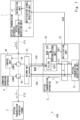
- Fig. 8 shows the submarine optical communication system 300 according to the third example embodiment.
- the submarine optical communication system 300 has a configuration in which the optical transmission apparatus 3 and the submarine branching apparatus 4 of the submarine optical communication system 100 are replaced by an optical transmission apparatus 6 and a submarine branching apparatus 7, respectively.
- the submarine optical communication system 300 is configured so as to be capable of further transmitting the main signal (also referred to as a second optical signal) from the optical transmission apparatus 2 towards the optical transmission apparatus 1.
- the main signal also referred to as a second optical signal
- the submarine optical branching apparatus 7 has a configuration in which a return unit 71 and optical switches 72 and 73 are added to the submarine branching apparatus 4.
- the control unit 44 controls the optical switches 42, 43, 72, and 73 according to the control signals CON1 to CON4, respectively.
- the return unit 71 (also referred to as a third return unit) can selectively return the monitoring signal MON output from the optical transmission apparatus 6 to the optical transmission apparatus 6.
- the optical transmission apparatus 2 and the optical switch 72 are connected with each other by an optical fiber FT3 of the trunk path.
- the optical switch 72 (also referred to as a third optical switch) can switch an output path (output destination) of the main signal received from the optical transmission apparatus 2 via the optical fiber FT3 to the branch path (i.e., a path through which the main signal is output to the optical fiber FB3) or the trunk path (i.e., a path through which the main signal is output to the optical switch 73) in accordance with the control signal CON3.
- the optical switch 73 (also referred to as a fourth optical switch) can switch an input path (input destination) of the received optical signal output to the branch path (i.e., a path through which the main signal is received via the optical fiber FB4) or the trunk path (i.e., a path through which the main signal is received from the optical switch 72 and output to the optical transmission apparatus 1 via the optical fiber FT4) in accordance with the control signal CON4.
- the branch path i.e., a path through which the main signal is received via the optical fiber FB4
- the trunk path i.e., a path through which the main signal is received from the optical switch 72 and output to the optical transmission apparatus 1 via the optical fiber FT4
- the optical transmission apparatus 6 has a configuration in which a return unit 61 is added to the optical transmission apparatus 3 and the detection unit 32 is replaced by a detection unit 62 having a similar configuration.
- the return unit 61 (also referred to as a fourth return unit) is inserted between the optical fiber FB1 of the branch path (the first branch path) on the return unit 41 side and the optical transmission/reception unit 31 and between the optical fiber FB4 of the branch path (the second branch path) on the return unit 71 side and the optical transmission/reception unit 31, and selectively returns only the monitoring signal MON made incident from the optical fiber FB1 to the optical fiber FB4.
- the return unit 61 includes a filter 61A and a coupler 61B.
- the filter 61A is a wavelength filter and selectively separates only a light having a wavelength of the monitoring signal MON.
- the separated monitoring signal MON is output to the optical fiber FB4 by the coupler 61B.
- the detection unit 62 detects the monitoring signal MON made incident from the optical fiber FB3 (also referred to as a third optical fiber) and outputs the detection signal DET that indicates the result of the detection to the notification unit 33.
- the monitoring signal MON output from the optical transmission apparatus 6 is transmitted through the uplink optical fiber FB2 of the branch path and arrives at the return unit 41 and then, it is returned to be transmitted through the downlink optical fiber FB1 of the branch path to thereby arrive at the return unit 61. Then, the monitoring signal MON is returned from the return unit 61 and output to the uplink optical fiber FB4 (the fourth optical fiber) of the adjacent branch path. Thereafter, the monitoring signal MON is transmitted through the uplink optical fiber FB4 of the branch path and arrives at the return unit 71, and then it is returned to be transmitted through the downlink optical fiber FB3 of the branch path and arrives at the detection unit 62.
- the return unit for the monitoring signal to the optical transmission apparatus of the branch station, it is possible to collectively detect failures that may occur in the two branch paths. Further, since the failures that may occur in the two branch paths can be detected without having to provide a detection unit for each branch path, it is possible to realize downsizing of the optical transmission apparatus.
- FIG. 9 shows a modified example of the submarine optical communication system according to the third example embodiment.
- a submarine optical communication system 301 shown in Fig. 9 has a configuration in which the optical transmission apparatus 6 is replaced by an optical transmission apparatus 6A.
- the optical transmission apparatus 6A has a configuration in which the return unit 61 of the optical transmission apparatus 6 is removed and the monitoring signal MON is returned inside the optical transmission/reception unit 31.
- the optical transmission/reception unit 31 includes, for example, a Wavelength Selectable Switch (hereinbelow referred to as the WSS) for separating and synthesizing each wavelength of the wavelength-division multiplexed signal.
- WSS 31A is provided on the first branch path side and WSS 31B is provided on the second branch path side.
- the WSS 31A and the WSS31B function as a return unit 63.
- the monitoring signal MON is input from an external signal generation unit (not shown) to the WSS 31A.
- the WSS 31A selectively outputs the monitoring signal MON to the optical fiber FB2 and selectively outputs the monitoring signal MON that is returned from the return unit 41 and made incident via the optical fiber FB1 to the WSS 31B.
- the WSS 31B selectively outputs the monitoring signal MON that is made incident from the WSS 31A to the optical fiber FB4.
- the monitoring signal MON output from the WSS 31B is returned from the return unit 71 and detected by the detection unit 62.
- the submarine optical communication system 301 of the present configuration can collectively detect failures that may occur in the two branch paths by providing a return unit for the monitoring signal to the optical transmission apparatus of the branch station in the same manner as in the submarine optical communication system 300. Further, since the failures that may occur in the two branch paths can be detected without having to provide a detection unit for each branch path, it is possible to realize downsizing of the optical transmission apparatus.
- the return unit for the monitoring signal by utilizing the WSS provided to the optical transmission/reception unit 31, which can be said as being advantageous in terms of downsizing the optical transmission apparatus compared to the submarine optical communication system 300 in which a return unit is provided externally to the optical transmission/reception unit 31 using an additional optical component.
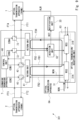
- FIG. 10 is a diagram showing a configuration of the submarine optical communication system 400 according to the fourth example embodiment.
- the submarine optical communication system 400 has a configuration in which the optical transmission apparatus 6 of the submarine optical communication system 300 is replaced by an optical transmission apparatus 8.
- the optical transmission apparatus 8 has a configuration in which the return unit 61 of the optical transmission apparatus 6 is removed and a branching unit 81 and the detection unit 32 are added.
- the branching unit 81 branches the monitoring signal MON output from the optical transmission/reception unit 31 into two. One of the branched monitoring signal MON is input to the uplink optical fiber FB2 of the first branch path and the other one of the branched monitoring signal MON is input to the uplink optical fiber FB4 of the second branch path.
- the monitoring signal MON input to the optical fiber FB2 is returned from the return unit 41 and is made incident on the detection unit 32 via the downlink optical fiber FB1 of the first branch path.
- the detection unit 32 outputs a detection signal DET1 that indicates the result of the detection by the monitoring signal MON to the notification unit 33.
- the monitoring signal MON input to the optical fiber FB4 is returned from the return unit 71 and is made incident on the detection unit 62 via the downlink optical fiber FB3 of the second branch.
- the detection unit 62 outputs a detection signal DET2 that indicates the result of the detection by the monitoring signal MON to the notification unit 33.
- the present configuration it is possible to collectively detect failures that may occur in the two branch paths in the same manner as in the submarine optical communication system 300 according to the third example embodiment. Further, since the failures that may occur in the two branch paths can be detected without having to generate a monitoring signal for each branch path, it is possible to realize downsizing of the optical transmission apparatus.
- a detection unit dedicated to each branch path is provided whereby it is possible to detect whether or not a failure has occurred in either one of the two branch paths.
- FIG. 11 shows a modified example of the submarine optical communication system according to the fourth example embodiment.
- a submarine optical communication system 401 shown in Fig. 11 has a configuration in which the optical transmission apparatus 8 of the submarine optical communication system 400 is replaced by an optical transmission apparatus 9.
- the optical transmission apparatus 9 has a configuration in which the detection unit 32 of the optical transmission apparatus 8 is removed and a branching unit 91 is added.
- the branching unit 81 branches the monitoring signal MON output from the optical transmission/reception unit 31 into two.
- One of the branched monitoring signal MON is input to the uplink optical fiber FB2 of the first branch path and the other one of the branched monitoring signal MON is input to the uplink optical fiber FB4 of the second branch path.
- the monitoring signal MON input to the optical fiber FB2 is returned from the return unit 41 and is made incident on the branching unit 91 via the downlink optical fiber FB1 of the first branch path.
- the branching unit 91 selectively branches the light having a wavelength of the monitoring signal MON and transmits lights having other wavelengths toward the optical transmission/reception unit 31. Accordingly, the monitoring signal MON is branched by the branching unit 91 and output to the detection unit 62.
- the monitoring signal MON input to the optical fiber FB4 is returned from the return unit 71 and is made incident on the detection unit 62 via the downlink optical fiber FB3 of the second branch.
- the detection unit 62 outputs the detection signal DET that indicates the result of the detection by the monitoring signal MON to the notification unit 33.
- the optical intensity of the monitoring signal MON detected by the detection unit 62 lowers. Therefore, in the present configuration, by having the detection unit 62 compare the optical intensity of the monitoring signal MON with the prescribed threshold value, it is possible to detect that a failure has occurred in at least one of the first or the second branch path.
- the submarine optical communication system 401 can eliminate the detection unit provided to the optical transmission apparatus at the branch station when compared with the submarine optical communication system 400. Therefore, it is advantageous in terms of realizing the downsizing of the optical transmission apparatus.
- the present disclosure is not limited to the example embodiments mentioned above and can be modified as appropriate without departing from the scope of the present disclosure.
- the monitoring signal was output to the uplink optical fiber of the branch path and the monitoring signal which was received via the downlink optical fiber has been detected, however, this is merely an example.
- a configuration in which the monitoring signal is output to the downlink optical fiber of the branch path and the monitoring signal which was received via the uplink optical fiber is detected as the monitoring signal may be adopted, although not within the scope of the appended claims.
- the receiver has been described as one that receives the DP-QPSK optical signal, however, this is merely an example.
- it may be configured such that optical signals of other modulation techniques can be transmitted.
Landscapes
- Engineering & Computer Science (AREA)
- Computer Networks & Wireless Communication (AREA)
- Physics & Mathematics (AREA)
- Electromagnetism (AREA)
- Signal Processing (AREA)
- Optical Communication System (AREA)
Claims (10)
- Optisches Unterseekommunikationssystem (100), das aufweist:eine erste optische Übertragungsvorrichtung (1), die so konfiguriert ist, dass sie ein erstes optisches Signal ausgibt;eine zweite optische Übertragungsvorrichtung (2);eine dritte optische Übertragungsvorrichtung (3), die so konfiguriert ist, dass sie ein optisches Signal und ein Überwachungssignal ausgibt; undeine Unterseeverzweigungsvorrichtung (4) mit einer ersten Rückführeinheit (41), die so konfiguriert ist, dass sie das von der dritten optischen Übertragungsvorrichtung (3) empfangene Überwachungssignal rückführt, und so konfiguriert ist, dass sie ein Ausgabeziel des von der ersten optischen Übertragungsvorrichtung (1) empfangenen ersten optischen Signals auf die zweite optische Übertragungsvorrichtung (2) oder die dritte optische Übertragungsvorrichtung (3) umschaltet, wobei die dritte optische Übertragungsvorrichtung (3) ferner so konfiguriert ist, dass sie das von der ersten Rückführeinheit (41) rückgeführte Überwachungssignal detektiert und der ersten optischen Übertragungsvorrichtung (1) ein Ergebnis der Detektion meldet, unddie erste optische Übertragungsvorrichtung (1) ferner so konfiguriert ist, dass sie der Unterseeverzweigungsvorrichtung (4) befiehlt, das Ausgabeziel des ersten optischen Signals in Übereinstimmung mit der Meldung umzuschalten.
- Optisches Unterseekommunikationssystem (100) nach Anspruch 1, wobei die Unterseeverzweigungsvorrichtung (4) so konfiguriert ist, dass sie das Ausgabeziel des ersten optischen Signals auf die erste optische Übertragungsvorrichtung (1) umschaltet, wenn eine optische Intensität des durch die dritte optische Übertragungsvorrichtung (3) empfangenen Überwachungssignals kleiner ist als ein vorgeschriebener Wert in einem Zustand, in dem das Ausgabeziel des ersten optischen Signals die dritte optische Übertragungsvorrichtung (3) ist.
- Optisches Unterseekommunikationssystem (100) nach Anspruch 2, wobei die Unterseeverzweigungsvorrichtung ferner aufweist:einen ersten optischen Schalter (42), der so konfiguriert ist, dass er das erste optische Signal von der ersten optischen Übertragungsvorrichtung (1) empfängt;einen zweiten optischen Schalter (43), der so konfiguriert ist, dass er das empfangene optische Signal zur zweiten optischen Übertragungsvorrichtung (2) ausgibt; undeine Steuereinheit (44), die so konfiguriert ist, dass sie den ersten und den zweiten optischen Schalter (42, 43) in Übereinstimmung mit dem Befehl von der ersten optischen Übertragungsvorrichtung (1) steuert, undwobei bei einer optischen Intensität des durch die dritte optische Übertragungsvorrichtung (3) empfangenen Überwachungssignals, die kleiner ist als der vorgeschriebene Wert, die Steuereinheit (44) umschaltet:das Ausgabeziel des ersten optischen Signals des ersten optischen Schalters von der dritten optischen Übertragungsvorrichtung (3) auf den zweiten optischen Schalter; undeine Eingabequelle des durch den zweiten optischen Schalter (43) empfangenen optischen Signals von der dritten optischen Übertragungsvorrichtung (3) auf den ersten optischen Schalter (42).
- Optisches Unterseekommunikationssystem (100) nach Anspruch 3, das ferner aufweist:eine erste optische Faser (FB1), die so konfiguriert ist, dass sie das von der Unterseeverzweigungsvorrichtung (4) ausgegebene erste optische Signal zur dritten optischen Übertragungsvorrichtung (3) überträgt; undeine zweite optische Faser (FB2), die so konfiguriert ist, dass sie ein von der dritten optischen Übertragungsvorrichtung (3) ausgegebenes optisches Signal zur Unterseeverzweigungsvorrichtung (4) überträgt, wobeidie dritte optische Übertragungsvorrichtung (3) aufweist:eine optische Sende-/Empfangseinheit (31), die so konfiguriert ist, dass sie das Überwachungssignal zu einer Komponente aus der ersten und der zweiten optischen Faser (FB1, FB2) ausgibt;eine Detektionseinheit (32), die so konfiguriert ist, dass sie das Überwachungssignal detektiert, das von der ersten Rückführeinheit (41) rückgeführt, über die andere Komponente aus der ersten und der zweiten optischen Faser (FB1, FB2) übertragen und in die dritte optische Übertragungsvorrichtung (3) eingegeben wird; undeine Meldeeinheit (33), die so konfiguriert ist, dass sie der ersten optischen Übertragungsvorrichtung (1) ein Ergebnis der Detektion durch die Detektionseinheit (32) meldet.
- Optisches Unterseekommunikationssystem (100) nach Anspruch 4, wobei die dritte optische Übertragungsvorrichtung (3) ferner eine zweite Rückführeinheit (51) aufweist, die so konfiguriert ist, dass sie ein optisches Signal mit einer vorgeschriebenen Wellenlänge, das in dem von der optischen Unterseevorrichtung (4) empfangenen ersten optischen Signal enthalten ist, zur optischen Sende-/Empfangseinheit (31) über die erste optische Faser (FB1) ausgibt und ein optisches Signal mit einer anderen Wellenlänge, das in dem von der optischen Unterseevorrichtung empfangenen ersten optischen Signal enthalten ist, zur Unterseeverzweigungsvorrichtung (4) über die zweite optische Faser (FB2) rückführt.
- Optisches Unterseekommunikationssystem (100) nach Anspruch 4, wobei die zweite optische Übertragungsvorrichtung (2) so konfiguriert ist, dass sie ein zweites optisches Signal ausgibt, und
die Unterseeverzweigungsvorrichtung (4) ferner eine dritte Rückführeinheit (71) aufweist, die so konfiguriert ist, dass sie das von der dritten optischen Übertragungsvorrichtung (3) empfangene Überwachungssignal rückführt, und ferner so konfiguriert ist, dass sie ein Ausgabeziel des von der zweiten optischen Übertragungsvorrichtung (2) empfangenen zweiten optischen Signals auf die erste optische Übertragungsvorrichtung (1) oder die dritte optische Übertragungsvorrichtung (3) umschaltet. - Optisches Unterseekommunikationssystem (100) nach Anspruch 6, das ferner aufweist:eine dritte optische Faser (FB3), die so konfiguriert ist, dass sie das von der Unterseeverzweigungsvorrichtung (4) ausgegebene zweite optische Signal zur dritten optischen Übertragungsvorrichtung (3) überträgt; undeine vierte optische Faser (4), die so konfiguriert ist, dass sie ein von der dritten optischen Übertragungsvorrichtung (3) ausgegebenes optisches Signal zur Unterseeverzweigungsvorrichtung (4) überträgt,wobei die Unterseeverzweigungsvorrichtung (4) ferner aufweist:einen dritten optischen Schalter (72), der so konfiguriert ist, dass er das von der zweiten optischen Übertragungsvorrichtung (2) empfangene zweite optische Signal empfängt; undeinen vierten optischen Schalter (73), der so konfiguriert ist, dass er das empfangene optische Signal zur ersten optischen Übertragungsvorrichtung (1) ausgibt, undwobei bei einer optischen Intensität des durch die dritte optische Übertragungsvorrichtung (3) empfangenen Überwachungssignals, die kleiner ist als der vorgeschriebene Wert, die Steuereinheit (44) umschaltet:das Ausgabeziel des zweiten optischen Signals des dritten optischen Schalters (72) von der dritten optischen Übertragungsvorrichtung (3) auf den vierten optischen Schalter (73); undeine Eingabequelle des durch den vierten optischen Schalter (73) empfangenen optischen Signals von der dritten optischen Übertragungsvorrichtung (3) auf den dritten optischen Schalter (72).
- Optisches Unterseekommunikationssystem (100) nach Anspruch 7, wobei die dritte optische Übertragungsvorrichtung (3) ferner eine vierte Rückführeinheit (61) aufweist, die so konfiguriert ist, dass sie das von der Unterseeverzweigungsvorrichtung (4) empfangene Überwachungssignal über die erste und die zweite optische Faser (FB1, FB2) rückführt und das rückgeführte Überwachungssignal zu einer Komponente aus der dritten und der vierten optischen Faser (FB3, FB4) ausgibt, und
die Detektionseinheit (62) ferner so konfiguriert ist, dass sie das Überwachungssignal detektiert, das von der vierten Rückführeinheit (61) rückgeführt, über die andere Komponente aus der dritten und der vierten optischen Faser (FB3, FB4) übertragen und durch die dritte optische Übertragungsvorrichtung (3) empfangen wird. - Optisches Unterseekommunikationssystem (100) nach Anspruch 6, wobei die dritte optische Übertragungsvorrichtung (3) ferner eine Verzweigungseinheit (81) aufweist, die so konfiguriert ist, dass sie das von der optischen Sende-/Empfangseinheit (31) ausgegebene Überwachungssignal verzweigt, eine Komponente aus dem verzweigten Überwachungssignal zur ersten Rückführeinheit (41) ausgibt und die andere Komponente aus dem verzweigten Überwachungssignal zur dritten Rückführeinheit (71) ausgibt, und
die Detektionseinheit (62) das von der ersten Rückführeinheit (41) rückgeführte Überwachungssignal und das von der dritten Rückführeinheit (71) rückgeführte Überwachungssignal detektiert. - Optisches Unterseekommunikationssystem (100) nach Anspruch 8, wobei die Detektionseinheit (62) aufweist:eine erste Detektionseinheit, die so konfiguriert ist, dass sie das von der ersten Rückführeinheit (41) rückgeführte Überwachungssignal detektiert und ein Ergebnis der Detektion zur Meldeeinheit (33) ausgibt; undeine zweite Detektionseinheit, die so konfiguriert ist, dass sie das von der dritten Rückführeinheit (71) rückgeführte Überwachungssignal detektiert und ein Ergebnis der Detektion zur Meldeeinheit (33) ausgibt.
Applications Claiming Priority (2)
| Application Number | Priority Date | Filing Date | Title |
|---|---|---|---|
| JP2017208874 | 2017-10-30 | ||
| PCT/JP2018/030333 WO2019087520A1 (ja) | 2017-10-30 | 2018-08-15 | 海底光通信システム及び海底分岐装置 |
Publications (3)
| Publication Number | Publication Date |
|---|---|
| EP3706330A1 EP3706330A1 (de) | 2020-09-09 |
| EP3706330A4 EP3706330A4 (de) | 2021-01-06 |
| EP3706330B1 true EP3706330B1 (de) | 2024-08-07 |
Family
ID=66331724
Family Applications (1)
| Application Number | Title | Priority Date | Filing Date |
|---|---|---|---|
| EP18872584.0A Active EP3706330B1 (de) | 2017-10-30 | 2018-08-15 | Optisches unterwasserkommunikationssystem |
Country Status (5)
| Country | Link |
|---|---|
| US (1) | US11705971B2 (de) |
| EP (1) | EP3706330B1 (de) |
| JP (1) | JP6962380B2 (de) |
| CN (1) | CN111295851B (de) |
| WO (1) | WO2019087520A1 (de) |
Families Citing this family (5)
| Publication number | Priority date | Publication date | Assignee | Title |
|---|---|---|---|---|
| US12457148B2 (en) * | 2020-06-19 | 2025-10-28 | Kookmin University Industry Academy Cooperation Foundation | Underwater network management system and operation method thereof |
| WO2022059345A1 (ja) * | 2020-09-17 | 2022-03-24 | 日本電気株式会社 | 監視用光信号到達調整装置、光通信用伝送路、光通信システム及び光通信用伝送路監視方法 |
| CN116325569A (zh) * | 2020-09-30 | 2023-06-23 | 日本电气株式会社 | 通信系统和用于通信系统的控制方法 |
| WO2023166587A1 (ja) * | 2022-03-02 | 2023-09-07 | 日本電気株式会社 | 陸揚げ局特定装置、陸揚げ局特定方法及び非一時的な記録媒体 |
| CN116582177B (zh) * | 2023-07-14 | 2023-09-19 | 华海通信技术有限公司 | 一种海缆系统故障后的数据保密方法及海缆系统 |
Citations (1)
| Publication number | Priority date | Publication date | Assignee | Title |
|---|---|---|---|---|
| JPH04325812A (ja) * | 1991-04-24 | 1992-11-16 | Fujitsu Ltd | 給電路短絡障害の探索方式 |
Family Cites Families (28)
| Publication number | Priority date | Publication date | Assignee | Title |
|---|---|---|---|---|
| JPS63253926A (ja) | 1987-04-10 | 1988-10-20 | Nippon Telegr & Teleph Corp <Ntt> | 海底光伝送路の分岐装置 |
| JPH0590997A (ja) | 1991-09-30 | 1993-04-09 | Nec Corp | 海底ケーブルシステムの分岐装置 |
| CN1195436A (zh) | 1995-08-04 | 1998-10-07 | 阿尔卡塔尔-阿尔斯托姆通用电气公司 | 分插复用器 |
| JPH09233023A (ja) * | 1996-02-20 | 1997-09-05 | Fujitsu Ltd | 光伝送システムの切替方法及び光増幅器 |
| JPH10150409A (ja) | 1996-11-19 | 1998-06-02 | Kokusai Denshin Denwa Co Ltd <Kdd> | 光海中分岐装置 |
| JP3440872B2 (ja) | 1999-05-07 | 2003-08-25 | 日本電気株式会社 | 光伝送システムにおける監視信号転送装置 |
| GB0126166D0 (en) * | 2001-10-31 | 2002-01-02 | Cit Alcatel | Apparatus and method for monitoring an optical transmission line |
| FR2851097B1 (fr) | 2003-02-11 | 2005-04-29 | Cit Alcatel | Unite de branchement integrable dans un systeme sous-marin de telecommunications, un tel systeme sous-marin de telecommunications et procede de reconfiguration d'un tel systeme sous-marin de telecommunications |
| JP4458928B2 (ja) | 2004-05-20 | 2010-04-28 | 富士通株式会社 | 光伝送システム |
| JP2007173943A (ja) * | 2005-12-19 | 2007-07-05 | Fujitsu Ltd | 光海底伝送システム |
| WO2008114438A1 (ja) * | 2007-03-20 | 2008-09-25 | Fujitsu Limited | 伝送路監視方法及び装置 |
| JP5002549B2 (ja) | 2008-07-08 | 2012-08-15 | 三菱電機ビルテクノサービス株式会社 | 異常設備検知システム |
| JP2011077808A (ja) | 2009-09-30 | 2011-04-14 | Fujitsu Ltd | 光伝送システム |
| US8401392B2 (en) | 2010-02-17 | 2013-03-19 | Tyco Electronics Subsea Communications Llc | Flexible branching unit and system including the same |
| US8483559B2 (en) * | 2011-01-07 | 2013-07-09 | Tyco Electronics Subsea Communications Llc | System and method for monitoring a branched optical communication system |
| JP5776254B2 (ja) | 2011-03-25 | 2015-09-09 | 富士通株式会社 | 通信システム、通信装置および通信方法 |
| US8750707B2 (en) | 2011-04-13 | 2014-06-10 | Tyco Electronics Subsea Communications Llc | System and method for establishing secure communications between transceivers in undersea optical communication systems |
| EP2701316A4 (de) | 2011-04-20 | 2014-11-19 | Nec Corp | Zerstreuungsvorrichtung mit oadm-funktion, optisches wellenlängenmultiplexnetzwerksystem und verfahren dafür |
| US8891957B2 (en) | 2011-07-13 | 2014-11-18 | Tyco Electronics Subsea Communications Llc | Method and system for fault recovery in an optical network |
| US9143845B2 (en) | 2011-12-22 | 2015-09-22 | Nec Corporation | Branching units and power line monitoring methods |
| US9276694B2 (en) | 2012-10-08 | 2016-03-01 | Tyco Electronics Subsea Communications Llc | Fault recovery in branched optical networks |
| EP2738959B1 (de) | 2012-11-30 | 2017-08-09 | Alcatel Lucent | System und Verfahren zur Bereitstellung von Unterwasserkommunikationsdaten |
| US20150093111A1 (en) * | 2013-10-02 | 2015-04-02 | Nec Laboratories America, Inc. | Secure wavelength selective switch-based reconfigurable branching unit for submarine network |
| CN107078812B (zh) | 2014-10-01 | 2019-11-12 | 日本电气株式会社 | 节点设备和用于控制节点设备的方法 |
| EP3273625B1 (de) * | 2015-03-16 | 2019-10-02 | NEC Corporation | Erweiterte abzweigvorrichtung und verfahren zur steuerung einer erweiterten abzweigvorrichtung |
| JP2017005384A (ja) | 2015-06-05 | 2017-01-05 | 富士通株式会社 | 光ネットワークシステム、光伝送装置及び検出方法 |
| JP2017208874A (ja) | 2016-05-16 | 2017-11-24 | 株式会社日立製作所 | 回転電機、回転電機駆動システム及び鉄道車両 |
| US9755734B1 (en) * | 2016-06-09 | 2017-09-05 | Google Inc. | Subsea optical communication network |
-
2018
- 2018-08-15 EP EP18872584.0A patent/EP3706330B1/de active Active
- 2018-08-15 US US16/756,200 patent/US11705971B2/en active Active
- 2018-08-15 WO PCT/JP2018/030333 patent/WO2019087520A1/ja not_active Ceased
- 2018-08-15 CN CN201880070924.5A patent/CN111295851B/zh active Active
- 2018-08-15 JP JP2019549875A patent/JP6962380B2/ja active Active
Patent Citations (1)
| Publication number | Priority date | Publication date | Assignee | Title |
|---|---|---|---|---|
| JPH04325812A (ja) * | 1991-04-24 | 1992-11-16 | Fujitsu Ltd | 給電路短絡障害の探索方式 |
Also Published As
| Publication number | Publication date |
|---|---|
| WO2019087520A1 (ja) | 2019-05-09 |
| JPWO2019087520A1 (ja) | 2020-11-12 |
| EP3706330A4 (de) | 2021-01-06 |
| CN111295851B (zh) | 2023-05-12 |
| JP6962380B2 (ja) | 2021-11-05 |
| US20210194597A1 (en) | 2021-06-24 |
| EP3706330A1 (de) | 2020-09-09 |
| US11705971B2 (en) | 2023-07-18 |
| CN111295851A (zh) | 2020-06-16 |
Similar Documents
| Publication | Publication Date | Title |
|---|---|---|
| US11705971B2 (en) | Submarine optical communication system and submarine branching apparatus | |
| US11165529B2 (en) | Optical wavelength multiplex transmission system, optical wavelength multiplex apparatus, and standby system checking method | |
| US20170230109A1 (en) | Optical communication device, optical communication system, and optical communication method | |
| US20170155981A1 (en) | Optical transmission device and optical transmission system | |
| JP2012244530A (ja) | ファイバ誤接続検出方法及びノード装置 | |
| US10484086B2 (en) | Optical branching unit | |
| US20230318702A1 (en) | Failure detection apparatus, cable branching device, and transmission path surveillance method | |
| US9912407B2 (en) | Optical relay device, optical communication system, optical relay method, and storage medium | |
| EP3057247B1 (de) | Vorrichtung für rekonfigurierbaren optischen add/drop-multiplexer | |
| EP3101827A1 (de) | Optisches netzwerksystem, vorrichtung zur optischen übertragung und fehlerauftrittabschnittsbestimmungsverfahren | |
| US11251895B2 (en) | Seabed branching device, optical seabed cable system, and optical communication method | |
| US20200259584A1 (en) | Submarine branching apparatus, optical submarine cable system, and optical communication method | |
| WO2012073419A1 (ja) | 波長多重光伝送システム、送信装置および受信装置 | |
| US20240364443A1 (en) | Optical transmission device and optical communication system | |
| CN107078812A (zh) | 节点设备和用于控制节点设备的方法 | |
| US20200313762A1 (en) | Submarine optical communication apparatus and submarine optical communication system | |
| US11914191B2 (en) | Optical branching/coupling device and optical branching/coupling method | |
| US20210336694A1 (en) | Path switching apparatus and path switching method | |
| US20220286203A1 (en) | Optical submarine branching apparatus, optical submarine cable system, switching method, non-transitory computer-readable medium | |
| JP4376263B2 (ja) | 光波長多重システム | |
| JP6560300B2 (ja) | 光伝送装置、光伝送ルート識別装置および光伝送ルート識別方法 | |
| JP2013070280A (ja) | 光通信装置、光通信システム、および経路制御方法 | |
| JP2006186538A (ja) | 光伝送装置及び光伝送路切換方法 | |
| WO2022219738A1 (ja) | 光通信システム、光送受信装置、及び、光通信方法 | |
| US11811448B2 (en) | Optical communication system, optical communication apparatus and optical communication method |
Legal Events
| Date | Code | Title | Description |
|---|---|---|---|
| STAA | Information on the status of an ep patent application or granted ep patent |
Free format text: STATUS: THE INTERNATIONAL PUBLICATION HAS BEEN MADE |
|
| PUAI | Public reference made under article 153(3) epc to a published international application that has entered the european phase |
Free format text: ORIGINAL CODE: 0009012 |
|
| STAA | Information on the status of an ep patent application or granted ep patent |
Free format text: STATUS: REQUEST FOR EXAMINATION WAS MADE |
|
| 17P | Request for examination filed |
Effective date: 20200524 |
|
| AK | Designated contracting states |
Kind code of ref document: A1 Designated state(s): AL AT BE BG CH CY CZ DE DK EE ES FI FR GB GR HR HU IE IS IT LI LT LU LV MC MK MT NL NO PL PT RO RS SE SI SK SM TR |
|
| AX | Request for extension of the european patent |
Extension state: BA ME |
|
| A4 | Supplementary search report drawn up and despatched |
Effective date: 20201204 |
|
| RIC1 | Information provided on ipc code assigned before grant |
Ipc: H04B 10/27 20130101ALI20201201BHEP Ipc: H04B 10/03 20130101AFI20201201BHEP Ipc: H04B 10/077 20130101ALI20201201BHEP |
|
| DAV | Request for validation of the european patent (deleted) | ||
| DAX | Request for extension of the european patent (deleted) | ||
| STAA | Information on the status of an ep patent application or granted ep patent |
Free format text: STATUS: EXAMINATION IS IN PROGRESS |
|
| 17Q | First examination report despatched |
Effective date: 20230509 |
|
| GRAP | Despatch of communication of intention to grant a patent |
Free format text: ORIGINAL CODE: EPIDOSNIGR1 |
|
| STAA | Information on the status of an ep patent application or granted ep patent |
Free format text: STATUS: GRANT OF PATENT IS INTENDED |
|
| INTG | Intention to grant announced |
Effective date: 20240404 |
|
| GRAS | Grant fee paid |
Free format text: ORIGINAL CODE: EPIDOSNIGR3 |
|
| GRAA | (expected) grant |
Free format text: ORIGINAL CODE: 0009210 |
|
| STAA | Information on the status of an ep patent application or granted ep patent |
Free format text: STATUS: THE PATENT HAS BEEN GRANTED |
|
| AK | Designated contracting states |
Kind code of ref document: B1 Designated state(s): AL AT BE BG CH CY CZ DE DK EE ES FI FR GB GR HR HU IE IS IT LI LT LU LV MC MK MT NL NO PL PT RO RS SE SI SK SM TR |
|
| REG | Reference to a national code |
Ref country code: GB Ref legal event code: FG4D |
|
| REG | Reference to a national code |
Ref country code: CH Ref legal event code: EP |
|
| REG | Reference to a national code |
Ref country code: IE Ref legal event code: FG4D |
|
| REG | Reference to a national code |
Ref country code: DE Ref legal event code: R096 Ref document number: 602018072917 Country of ref document: DE |
|
| REG | Reference to a national code |
Ref country code: LT Ref legal event code: MG9D |
|
| REG | Reference to a national code |
Ref country code: NL Ref legal event code: MP Effective date: 20240807 |
|
| PG25 | Lapsed in a contracting state [announced via postgrant information from national office to epo] |
Ref country code: NO Free format text: LAPSE BECAUSE OF FAILURE TO SUBMIT A TRANSLATION OF THE DESCRIPTION OR TO PAY THE FEE WITHIN THE PRESCRIBED TIME-LIMIT Effective date: 20241107 |
|
| REG | Reference to a national code |
Ref country code: AT Ref legal event code: MK05 Ref document number: 1712064 Country of ref document: AT Kind code of ref document: T Effective date: 20240807 |
|
| PG25 | Lapsed in a contracting state [announced via postgrant information from national office to epo] |
Ref country code: PT Free format text: LAPSE BECAUSE OF FAILURE TO SUBMIT A TRANSLATION OF THE DESCRIPTION OR TO PAY THE FEE WITHIN THE PRESCRIBED TIME-LIMIT Effective date: 20241209 Ref country code: NL Free format text: LAPSE BECAUSE OF FAILURE TO SUBMIT A TRANSLATION OF THE DESCRIPTION OR TO PAY THE FEE WITHIN THE PRESCRIBED TIME-LIMIT Effective date: 20240807 Ref country code: FI Free format text: LAPSE BECAUSE OF FAILURE TO SUBMIT A TRANSLATION OF THE DESCRIPTION OR TO PAY THE FEE WITHIN THE PRESCRIBED TIME-LIMIT Effective date: 20240807 Ref country code: PL Free format text: LAPSE BECAUSE OF FAILURE TO SUBMIT A TRANSLATION OF THE DESCRIPTION OR TO PAY THE FEE WITHIN THE PRESCRIBED TIME-LIMIT Effective date: 20240807 Ref country code: GR Free format text: LAPSE BECAUSE OF FAILURE TO SUBMIT A TRANSLATION OF THE DESCRIPTION OR TO PAY THE FEE WITHIN THE PRESCRIBED TIME-LIMIT Effective date: 20241108 |
|
| PG25 | Lapsed in a contracting state [announced via postgrant information from national office to epo] |
Ref country code: BG Free format text: LAPSE BECAUSE OF FAILURE TO SUBMIT A TRANSLATION OF THE DESCRIPTION OR TO PAY THE FEE WITHIN THE PRESCRIBED TIME-LIMIT Effective date: 20240807 |
|
| PG25 | Lapsed in a contracting state [announced via postgrant information from national office to epo] |
Ref country code: LV Free format text: LAPSE BECAUSE OF FAILURE TO SUBMIT A TRANSLATION OF THE DESCRIPTION OR TO PAY THE FEE WITHIN THE PRESCRIBED TIME-LIMIT Effective date: 20240807 |
|
| PG25 | Lapsed in a contracting state [announced via postgrant information from national office to epo] |
Ref country code: AT Free format text: LAPSE BECAUSE OF FAILURE TO SUBMIT A TRANSLATION OF THE DESCRIPTION OR TO PAY THE FEE WITHIN THE PRESCRIBED TIME-LIMIT Effective date: 20240807 Ref country code: IS Free format text: LAPSE BECAUSE OF FAILURE TO SUBMIT A TRANSLATION OF THE DESCRIPTION OR TO PAY THE FEE WITHIN THE PRESCRIBED TIME-LIMIT Effective date: 20241207 |
|
| PG25 | Lapsed in a contracting state [announced via postgrant information from national office to epo] |
Ref country code: HR Free format text: LAPSE BECAUSE OF FAILURE TO SUBMIT A TRANSLATION OF THE DESCRIPTION OR TO PAY THE FEE WITHIN THE PRESCRIBED TIME-LIMIT Effective date: 20240807 |
|
| PG25 | Lapsed in a contracting state [announced via postgrant information from national office to epo] |
Ref country code: RS Free format text: LAPSE BECAUSE OF FAILURE TO SUBMIT A TRANSLATION OF THE DESCRIPTION OR TO PAY THE FEE WITHIN THE PRESCRIBED TIME-LIMIT Effective date: 20241107 Ref country code: ES Free format text: LAPSE BECAUSE OF FAILURE TO SUBMIT A TRANSLATION OF THE DESCRIPTION OR TO PAY THE FEE WITHIN THE PRESCRIBED TIME-LIMIT Effective date: 20240807 |
|
| PG25 | Lapsed in a contracting state [announced via postgrant information from national office to epo] |
Ref country code: RS Free format text: LAPSE BECAUSE OF FAILURE TO SUBMIT A TRANSLATION OF THE DESCRIPTION OR TO PAY THE FEE WITHIN THE PRESCRIBED TIME-LIMIT Effective date: 20241107 Ref country code: PT Free format text: LAPSE BECAUSE OF FAILURE TO SUBMIT A TRANSLATION OF THE DESCRIPTION OR TO PAY THE FEE WITHIN THE PRESCRIBED TIME-LIMIT Effective date: 20241209 Ref country code: PL Free format text: LAPSE BECAUSE OF FAILURE TO SUBMIT A TRANSLATION OF THE DESCRIPTION OR TO PAY THE FEE WITHIN THE PRESCRIBED TIME-LIMIT Effective date: 20240807 Ref country code: NO Free format text: LAPSE BECAUSE OF FAILURE TO SUBMIT A TRANSLATION OF THE DESCRIPTION OR TO PAY THE FEE WITHIN THE PRESCRIBED TIME-LIMIT Effective date: 20241107 Ref country code: NL Free format text: LAPSE BECAUSE OF FAILURE TO SUBMIT A TRANSLATION OF THE DESCRIPTION OR TO PAY THE FEE WITHIN THE PRESCRIBED TIME-LIMIT Effective date: 20240807 Ref country code: LV Free format text: LAPSE BECAUSE OF FAILURE TO SUBMIT A TRANSLATION OF THE DESCRIPTION OR TO PAY THE FEE WITHIN THE PRESCRIBED TIME-LIMIT Effective date: 20240807 Ref country code: IS Free format text: LAPSE BECAUSE OF FAILURE TO SUBMIT A TRANSLATION OF THE DESCRIPTION OR TO PAY THE FEE WITHIN THE PRESCRIBED TIME-LIMIT Effective date: 20241207 Ref country code: HR Free format text: LAPSE BECAUSE OF FAILURE TO SUBMIT A TRANSLATION OF THE DESCRIPTION OR TO PAY THE FEE WITHIN THE PRESCRIBED TIME-LIMIT Effective date: 20240807 Ref country code: GR Free format text: LAPSE BECAUSE OF FAILURE TO SUBMIT A TRANSLATION OF THE DESCRIPTION OR TO PAY THE FEE WITHIN THE PRESCRIBED TIME-LIMIT Effective date: 20241108 Ref country code: FI Free format text: LAPSE BECAUSE OF FAILURE TO SUBMIT A TRANSLATION OF THE DESCRIPTION OR TO PAY THE FEE WITHIN THE PRESCRIBED TIME-LIMIT Effective date: 20240807 Ref country code: ES Free format text: LAPSE BECAUSE OF FAILURE TO SUBMIT A TRANSLATION OF THE DESCRIPTION OR TO PAY THE FEE WITHIN THE PRESCRIBED TIME-LIMIT Effective date: 20240807 Ref country code: BG Free format text: LAPSE BECAUSE OF FAILURE TO SUBMIT A TRANSLATION OF THE DESCRIPTION OR TO PAY THE FEE WITHIN THE PRESCRIBED TIME-LIMIT Effective date: 20240807 Ref country code: AT Free format text: LAPSE BECAUSE OF FAILURE TO SUBMIT A TRANSLATION OF THE DESCRIPTION OR TO PAY THE FEE WITHIN THE PRESCRIBED TIME-LIMIT Effective date: 20240807 |
|
| REG | Reference to a national code |
Ref country code: DE Ref legal event code: R119 Ref document number: 602018072917 Country of ref document: DE |
|
| REG | Reference to a national code |
Ref country code: CH Ref legal event code: PL |
|
| PG25 | Lapsed in a contracting state [announced via postgrant information from national office to epo] |
Ref country code: SM Free format text: LAPSE BECAUSE OF FAILURE TO SUBMIT A TRANSLATION OF THE DESCRIPTION OR TO PAY THE FEE WITHIN THE PRESCRIBED TIME-LIMIT Effective date: 20240807 Ref country code: DK Free format text: LAPSE BECAUSE OF FAILURE TO SUBMIT A TRANSLATION OF THE DESCRIPTION OR TO PAY THE FEE WITHIN THE PRESCRIBED TIME-LIMIT Effective date: 20240807 Ref country code: RO Free format text: LAPSE BECAUSE OF FAILURE TO SUBMIT A TRANSLATION OF THE DESCRIPTION OR TO PAY THE FEE WITHIN THE PRESCRIBED TIME-LIMIT Effective date: 20240807 |
|
| PG25 | Lapsed in a contracting state [announced via postgrant information from national office to epo] |
Ref country code: LU Free format text: LAPSE BECAUSE OF NON-PAYMENT OF DUE FEES Effective date: 20240815 |
|
| PG25 | Lapsed in a contracting state [announced via postgrant information from national office to epo] |
Ref country code: CH Free format text: LAPSE BECAUSE OF NON-PAYMENT OF DUE FEES Effective date: 20240831 Ref country code: EE Free format text: LAPSE BECAUSE OF FAILURE TO SUBMIT A TRANSLATION OF THE DESCRIPTION OR TO PAY THE FEE WITHIN THE PRESCRIBED TIME-LIMIT Effective date: 20240807 |
|
| PG25 | Lapsed in a contracting state [announced via postgrant information from national office to epo] |
Ref country code: CZ Free format text: LAPSE BECAUSE OF FAILURE TO SUBMIT A TRANSLATION OF THE DESCRIPTION OR TO PAY THE FEE WITHIN THE PRESCRIBED TIME-LIMIT Effective date: 20240807 |
|
| PG25 | Lapsed in a contracting state [announced via postgrant information from national office to epo] |
Ref country code: SK Free format text: LAPSE BECAUSE OF FAILURE TO SUBMIT A TRANSLATION OF THE DESCRIPTION OR TO PAY THE FEE WITHIN THE PRESCRIBED TIME-LIMIT Effective date: 20240807 |
|
| PLBE | No opposition filed within time limit |
Free format text: ORIGINAL CODE: 0009261 |
|
| STAA | Information on the status of an ep patent application or granted ep patent |
Free format text: STATUS: NO OPPOSITION FILED WITHIN TIME LIMIT |
|
| REG | Reference to a national code |
Ref country code: BE Ref legal event code: MM Effective date: 20240831 |
|
| PG25 | Lapsed in a contracting state [announced via postgrant information from national office to epo] |
Ref country code: MC Free format text: LAPSE BECAUSE OF FAILURE TO SUBMIT A TRANSLATION OF THE DESCRIPTION OR TO PAY THE FEE WITHIN THE PRESCRIBED TIME-LIMIT Effective date: 20240807 |
|
| PG25 | Lapsed in a contracting state [announced via postgrant information from national office to epo] |
Ref country code: DE Free format text: LAPSE BECAUSE OF NON-PAYMENT OF DUE FEES Effective date: 20250301 |
|
| PG25 | Lapsed in a contracting state [announced via postgrant information from national office to epo] |
Ref country code: BE Free format text: LAPSE BECAUSE OF NON-PAYMENT OF DUE FEES Effective date: 20240831 |
|
| 26N | No opposition filed |
Effective date: 20250508 |
|
| GBPC | Gb: european patent ceased through non-payment of renewal fee |
Effective date: 20241107 |
|
| PG25 | Lapsed in a contracting state [announced via postgrant information from national office to epo] |
Ref country code: IE Free format text: LAPSE BECAUSE OF NON-PAYMENT OF DUE FEES Effective date: 20240815 |
|
| PG25 | Lapsed in a contracting state [announced via postgrant information from national office to epo] |
Ref country code: SE Free format text: LAPSE BECAUSE OF FAILURE TO SUBMIT A TRANSLATION OF THE DESCRIPTION OR TO PAY THE FEE WITHIN THE PRESCRIBED TIME-LIMIT Effective date: 20240807 |
|
| PG25 | Lapsed in a contracting state [announced via postgrant information from national office to epo] |
Ref country code: GB Free format text: LAPSE BECAUSE OF NON-PAYMENT OF DUE FEES Effective date: 20241107 |
|
| PGFP | Annual fee paid to national office [announced via postgrant information from national office to epo] |
Ref country code: FR Payment date: 20250828 Year of fee payment: 8 |
|
| PG25 | Lapsed in a contracting state [announced via postgrant information from national office to epo] |
Ref country code: IT Free format text: LAPSE BECAUSE OF FAILURE TO SUBMIT A TRANSLATION OF THE DESCRIPTION OR TO PAY THE FEE WITHIN THE PRESCRIBED TIME-LIMIT Effective date: 20240807 Ref country code: CY Free format text: LAPSE BECAUSE OF FAILURE TO SUBMIT A TRANSLATION OF THE DESCRIPTION OR TO PAY THE FEE WITHIN THE PRESCRIBED TIME-LIMIT; INVALID AB INITIO Effective date: 20180815 |
|
| PG25 | Lapsed in a contracting state [announced via postgrant information from national office to epo] |
Ref country code: HU Free format text: LAPSE BECAUSE OF FAILURE TO SUBMIT A TRANSLATION OF THE DESCRIPTION OR TO PAY THE FEE WITHIN THE PRESCRIBED TIME-LIMIT; INVALID AB INITIO Effective date: 20180815 |