EP3706208B1 - Positive active material for rechargeable lithium battery, method of preparing the same and rechargeable lithium battery including the same - Google Patents
Positive active material for rechargeable lithium battery, method of preparing the same and rechargeable lithium battery including the same Download PDFInfo
- Publication number
- EP3706208B1 EP3706208B1 EP20161073.0A EP20161073A EP3706208B1 EP 3706208 B1 EP3706208 B1 EP 3706208B1 EP 20161073 A EP20161073 A EP 20161073A EP 3706208 B1 EP3706208 B1 EP 3706208B1
- Authority
- EP
- European Patent Office
- Prior art keywords
- compound
- active material
- charge
- particles
- positive active
- Prior art date
- Legal status (The legal status is an assumption and is not a legal conclusion. Google has not performed a legal analysis and makes no representation as to the accuracy of the status listed.)
- Active
Links
- 239000007774 positive electrode material Substances 0.000 title claims description 72
- 229910052744 lithium Inorganic materials 0.000 title claims description 51
- WHXSMMKQMYFTQS-UHFFFAOYSA-N Lithium Chemical compound [Li] WHXSMMKQMYFTQS-UHFFFAOYSA-N 0.000 title claims description 47
- 238000000034 method Methods 0.000 title description 19
- 150000001875 compounds Chemical class 0.000 claims description 118
- 239000002245 particle Substances 0.000 claims description 79
- 239000000126 substance Substances 0.000 claims description 34
- 229910052759 nickel Inorganic materials 0.000 claims description 28
- 238000002156 mixing Methods 0.000 claims description 24
- 229910052751 metal Inorganic materials 0.000 claims description 18
- 239000007773 negative electrode material Substances 0.000 claims description 18
- 150000001768 cations Chemical class 0.000 claims description 16
- 239000002344 surface layer Substances 0.000 claims description 12
- 239000002184 metal Substances 0.000 claims description 11
- 239000003792 electrolyte Substances 0.000 claims description 10
- 229910052802 copper Inorganic materials 0.000 claims description 9
- 229910052782 aluminium Inorganic materials 0.000 claims description 8
- 229910052748 manganese Inorganic materials 0.000 claims description 8
- 229910052738 indium Inorganic materials 0.000 claims description 7
- 229910052749 magnesium Inorganic materials 0.000 claims description 7
- 229910052718 tin Inorganic materials 0.000 claims description 7
- 229910052720 vanadium Inorganic materials 0.000 claims description 7
- 229910052725 zinc Inorganic materials 0.000 claims description 7
- 229910052804 chromium Inorganic materials 0.000 claims description 6
- 229910052733 gallium Inorganic materials 0.000 claims description 6
- 229910052742 iron Inorganic materials 0.000 claims description 6
- 229910052750 molybdenum Inorganic materials 0.000 claims description 6
- 229910052758 niobium Inorganic materials 0.000 claims description 6
- 238000004626 scanning electron microscopy Methods 0.000 claims description 6
- 229910052719 titanium Inorganic materials 0.000 claims description 6
- 229910052721 tungsten Inorganic materials 0.000 claims description 6
- 229910052726 zirconium Inorganic materials 0.000 claims description 6
- 229910052684 Cerium Inorganic materials 0.000 claims description 5
- 229910052746 lanthanum Inorganic materials 0.000 claims description 5
- 208000028659 discharge Diseases 0.000 description 111
- PXHVJJICTQNCMI-UHFFFAOYSA-N Nickel Chemical compound [Ni] PXHVJJICTQNCMI-UHFFFAOYSA-N 0.000 description 69
- 230000000052 comparative effect Effects 0.000 description 44
- 239000011572 manganese Substances 0.000 description 27
- 239000000203 mixture Substances 0.000 description 26
- -1 region Substances 0.000 description 22
- 239000010410 layer Substances 0.000 description 17
- 229910003002 lithium salt Inorganic materials 0.000 description 11
- 159000000002 lithium salts Chemical class 0.000 description 11
- 239000000047 product Substances 0.000 description 11
- 229910001416 lithium ion Inorganic materials 0.000 description 10
- HBBGRARXTFLTSG-UHFFFAOYSA-N Lithium ion Chemical compound [Li+] HBBGRARXTFLTSG-UHFFFAOYSA-N 0.000 description 9
- 238000010438 heat treatment Methods 0.000 description 9
- WMFOQBRAJBCJND-UHFFFAOYSA-M Lithium hydroxide Chemical compound [Li+].[OH-] WMFOQBRAJBCJND-UHFFFAOYSA-M 0.000 description 8
- 239000011230 binding agent Substances 0.000 description 8
- 239000010949 copper Substances 0.000 description 8
- 230000008569 process Effects 0.000 description 8
- 239000004698 Polyethylene Substances 0.000 description 7
- 239000004743 Polypropylene Substances 0.000 description 7
- 239000004020 conductor Substances 0.000 description 7
- 229920000573 polyethylene Polymers 0.000 description 7
- 229920001155 polypropylene Polymers 0.000 description 7
- 229910052723 transition metal Inorganic materials 0.000 description 7
- 150000003624 transition metals Chemical class 0.000 description 7
- 230000008859 change Effects 0.000 description 6
- 239000007789 gas Substances 0.000 description 6
- KWGKDLIKAYFUFQ-UHFFFAOYSA-M lithium chloride Chemical compound [Li+].[Cl-] KWGKDLIKAYFUFQ-UHFFFAOYSA-M 0.000 description 6
- 239000000463 material Substances 0.000 description 6
- 239000003960 organic solvent Substances 0.000 description 6
- 239000011163 secondary particle Substances 0.000 description 6
- OKTJSMMVPCPJKN-UHFFFAOYSA-N Carbon Chemical group [C] OKTJSMMVPCPJKN-UHFFFAOYSA-N 0.000 description 5
- KMTRUDSVKNLOMY-UHFFFAOYSA-N Ethylene carbonate Chemical compound O=C1OCCO1 KMTRUDSVKNLOMY-UHFFFAOYSA-N 0.000 description 5
- VEQPNABPJHWNSG-UHFFFAOYSA-N Nickel(2+) Chemical compound [Ni+2] VEQPNABPJHWNSG-UHFFFAOYSA-N 0.000 description 5
- QVGXLLKOCUKJST-UHFFFAOYSA-N atomic oxygen Chemical compound [O] QVGXLLKOCUKJST-UHFFFAOYSA-N 0.000 description 5
- 239000013065 commercial product Substances 0.000 description 5
- 238000001816 cooling Methods 0.000 description 5
- 238000011156 evaluation Methods 0.000 description 5
- 150000002500 ions Chemical class 0.000 description 5
- XGZVUEUWXADBQD-UHFFFAOYSA-L lithium carbonate Chemical compound [Li+].[Li+].[O-]C([O-])=O XGZVUEUWXADBQD-UHFFFAOYSA-L 0.000 description 5
- 238000004519 manufacturing process Methods 0.000 description 5
- 229910052760 oxygen Inorganic materials 0.000 description 5
- 239000001301 oxygen Substances 0.000 description 5
- 239000010936 titanium Substances 0.000 description 5
- RYGMFSIKBFXOCR-UHFFFAOYSA-N Copper Chemical compound [Cu] RYGMFSIKBFXOCR-UHFFFAOYSA-N 0.000 description 4
- 239000002033 PVDF binder Substances 0.000 description 4
- 229910052783 alkali metal Inorganic materials 0.000 description 4
- 239000003575 carbonaceous material Substances 0.000 description 4
- IIPYXGDZVMZOAP-UHFFFAOYSA-N lithium nitrate Chemical compound [Li+].[O-][N+]([O-])=O IIPYXGDZVMZOAP-UHFFFAOYSA-N 0.000 description 4
- 229920002981 polyvinylidene fluoride Polymers 0.000 description 4
- PBKONEOXTCPAFI-UHFFFAOYSA-N 1,2,4-trichlorobenzene Chemical compound ClC1=CC=C(Cl)C(Cl)=C1 PBKONEOXTCPAFI-UHFFFAOYSA-N 0.000 description 3
- RFFLAFLAYFXFSW-UHFFFAOYSA-N 1,2-dichlorobenzene Chemical compound ClC1=CC=CC=C1Cl RFFLAFLAYFXFSW-UHFFFAOYSA-N 0.000 description 3
- UHOVQNZJYSORNB-UHFFFAOYSA-N Benzene Chemical compound C1=CC=CC=C1 UHOVQNZJYSORNB-UHFFFAOYSA-N 0.000 description 3
- LFQSCWFLJHTTHZ-UHFFFAOYSA-N Ethanol Chemical compound CCO LFQSCWFLJHTTHZ-UHFFFAOYSA-N 0.000 description 3
- XEKOWRVHYACXOJ-UHFFFAOYSA-N Ethyl acetate Chemical compound CCOC(C)=O XEKOWRVHYACXOJ-UHFFFAOYSA-N 0.000 description 3
- KFZMGEQAYNKOFK-UHFFFAOYSA-N Isopropanol Chemical compound CC(C)O KFZMGEQAYNKOFK-UHFFFAOYSA-N 0.000 description 3
- ZMXDDKWLCZADIW-UHFFFAOYSA-N N,N-Dimethylformamide Chemical compound CN(C)C=O ZMXDDKWLCZADIW-UHFFFAOYSA-N 0.000 description 3
- VYPSYNLAJGMNEJ-UHFFFAOYSA-N Silicium dioxide Chemical compound O=[Si]=O VYPSYNLAJGMNEJ-UHFFFAOYSA-N 0.000 description 3
- YXFVVABEGXRONW-UHFFFAOYSA-N Toluene Chemical compound CC1=CC=CC=C1 YXFVVABEGXRONW-UHFFFAOYSA-N 0.000 description 3
- 229920005993 acrylate styrene-butadiene rubber polymer Polymers 0.000 description 3
- 239000000654 additive Substances 0.000 description 3
- 230000000996 additive effect Effects 0.000 description 3
- 150000001340 alkali metals Chemical class 0.000 description 3
- 229910045601 alloy Inorganic materials 0.000 description 3
- 239000000956 alloy Substances 0.000 description 3
- 229910021383 artificial graphite Inorganic materials 0.000 description 3
- 230000003247 decreasing effect Effects 0.000 description 3
- 239000000835 fiber Substances 0.000 description 3
- 239000011888 foil Substances 0.000 description 3
- 238000003780 insertion Methods 0.000 description 3
- 230000037431 insertion Effects 0.000 description 3
- 239000003273 ketjen black Substances 0.000 description 3
- 229910021437 lithium-transition metal oxide Inorganic materials 0.000 description 3
- 229910021382 natural graphite Inorganic materials 0.000 description 3
- 239000011356 non-aqueous organic solvent Substances 0.000 description 3
- 230000001590 oxidative effect Effects 0.000 description 3
- 239000003232 water-soluble binding agent Substances 0.000 description 3
- ZZXUZKXVROWEIF-UHFFFAOYSA-N 1,2-butylene carbonate Chemical compound CCC1COC(=O)O1 ZZXUZKXVROWEIF-UHFFFAOYSA-N 0.000 description 2
- GOYDNIKZWGIXJT-UHFFFAOYSA-N 1,2-difluorobenzene Chemical compound FC1=CC=CC=C1F GOYDNIKZWGIXJT-UHFFFAOYSA-N 0.000 description 2
- 229920000049 Carbon (fiber) Polymers 0.000 description 2
- 229920002134 Carboxymethyl cellulose Polymers 0.000 description 2
- OIFBSDVPJOWBCH-UHFFFAOYSA-N Diethyl carbonate Chemical compound CCOC(=O)OCC OIFBSDVPJOWBCH-UHFFFAOYSA-N 0.000 description 2
- 229910001290 LiPF6 Inorganic materials 0.000 description 2
- 229910001228 Li[Ni1/3Co1/3Mn1/3]O2 (NCM 111) Inorganic materials 0.000 description 2
- PWHULOQIROXLJO-UHFFFAOYSA-N Manganese Chemical compound [Mn] PWHULOQIROXLJO-UHFFFAOYSA-N 0.000 description 2
- 229920000265 Polyparaphenylene Polymers 0.000 description 2
- 239000004372 Polyvinyl alcohol Substances 0.000 description 2
- WYURNTSHIVDZCO-UHFFFAOYSA-N Tetrahydrofuran Chemical compound C1CCOC1 WYURNTSHIVDZCO-UHFFFAOYSA-N 0.000 description 2
- 239000006230 acetylene black Substances 0.000 description 2
- 229910052784 alkaline earth metal Inorganic materials 0.000 description 2
- 150000001342 alkaline earth metals Chemical class 0.000 description 2
- XAGFODPZIPBFFR-UHFFFAOYSA-N aluminium Chemical compound [Al] XAGFODPZIPBFFR-UHFFFAOYSA-N 0.000 description 2
- 229910003481 amorphous carbon Inorganic materials 0.000 description 2
- 150000004945 aromatic hydrocarbons Chemical class 0.000 description 2
- 229910052795 boron group element Inorganic materials 0.000 description 2
- 229910052791 calcium Inorganic materials 0.000 description 2
- 229910052799 carbon Inorganic materials 0.000 description 2
- 239000004917 carbon fiber Substances 0.000 description 2
- 229910052800 carbon group element Inorganic materials 0.000 description 2
- 239000001913 cellulose Substances 0.000 description 2
- 229920002678 cellulose Polymers 0.000 description 2
- 229910052798 chalcogen Inorganic materials 0.000 description 2
- 238000006243 chemical reaction Methods 0.000 description 2
- MVPPADPHJFYWMZ-UHFFFAOYSA-N chlorobenzene Chemical compound ClC1=CC=CC=C1 MVPPADPHJFYWMZ-UHFFFAOYSA-N 0.000 description 2
- 229910017052 cobalt Inorganic materials 0.000 description 2
- 239000010941 cobalt Substances 0.000 description 2
- GUTLYIVDDKVIGB-UHFFFAOYSA-N cobalt atom Chemical compound [Co] GUTLYIVDDKVIGB-UHFFFAOYSA-N 0.000 description 2
- 229920001940 conductive polymer Polymers 0.000 description 2
- 229920001577 copolymer Polymers 0.000 description 2
- JHIVVAPYMSGYDF-UHFFFAOYSA-N cyclohexanone Chemical compound O=C1CCCCC1 JHIVVAPYMSGYDF-UHFFFAOYSA-N 0.000 description 2
- IEJIGPNLZYLLBP-UHFFFAOYSA-N dimethyl carbonate Chemical compound COC(=O)OC IEJIGPNLZYLLBP-UHFFFAOYSA-N 0.000 description 2
- VUPKGFBOKBGHFZ-UHFFFAOYSA-N dipropyl carbonate Chemical compound CCCOC(=O)OCCC VUPKGFBOKBGHFZ-UHFFFAOYSA-N 0.000 description 2
- 238000009826 distribution Methods 0.000 description 2
- 239000003822 epoxy resin Substances 0.000 description 2
- JBTWLSYIZRCDFO-UHFFFAOYSA-N ethyl methyl carbonate Chemical compound CCOC(=O)OC JBTWLSYIZRCDFO-UHFFFAOYSA-N 0.000 description 2
- FKRCODPIKNYEAC-UHFFFAOYSA-N ethyl propionate Chemical compound CCOC(=O)CC FKRCODPIKNYEAC-UHFFFAOYSA-N 0.000 description 2
- QKBJDEGZZJWPJA-UHFFFAOYSA-N ethyl propyl carbonate Chemical compound [CH2]COC(=O)OCCC QKBJDEGZZJWPJA-UHFFFAOYSA-N 0.000 description 2
- 238000000445 field-emission scanning electron microscopy Methods 0.000 description 2
- 239000006260 foam Substances 0.000 description 2
- 230000006872 improvement Effects 0.000 description 2
- 238000007561 laser diffraction method Methods 0.000 description 2
- 229910052745 lead Inorganic materials 0.000 description 2
- 239000007769 metal material Substances 0.000 description 2
- VNWKTOKETHGBQD-UHFFFAOYSA-N methane Chemical compound C VNWKTOKETHGBQD-UHFFFAOYSA-N 0.000 description 2
- KKQAVHGECIBFRQ-UHFFFAOYSA-N methyl propyl carbonate Chemical compound CCCOC(=O)OC KKQAVHGECIBFRQ-UHFFFAOYSA-N 0.000 description 2
- 239000003235 non-water-soluble binding agent Substances 0.000 description 2
- 229910052696 pnictogen Inorganic materials 0.000 description 2
- 229920000647 polyepoxide Polymers 0.000 description 2
- 229920001343 polytetrafluoroethylene Polymers 0.000 description 2
- 239000004810 polytetrafluoroethylene Substances 0.000 description 2
- 229920002635 polyurethane Polymers 0.000 description 2
- 239000004814 polyurethane Substances 0.000 description 2
- 229920002451 polyvinyl alcohol Polymers 0.000 description 2
- 229920000915 polyvinyl chloride Polymers 0.000 description 2
- 239000004800 polyvinyl chloride Substances 0.000 description 2
- 229920002620 polyvinyl fluoride Polymers 0.000 description 2
- 229920000036 polyvinylpyrrolidone Polymers 0.000 description 2
- 239000001267 polyvinylpyrrolidone Substances 0.000 description 2
- 235000013855 polyvinylpyrrolidone Nutrition 0.000 description 2
- 229910052700 potassium Inorganic materials 0.000 description 2
- 239000000843 powder Substances 0.000 description 2
- YKYONYBAUNKHLG-UHFFFAOYSA-N propyl acetate Chemical compound CCCOC(C)=O YKYONYBAUNKHLG-UHFFFAOYSA-N 0.000 description 2
- RUOJZAUFBMNUDX-UHFFFAOYSA-N propylene carbonate Chemical compound CC1COC(=O)O1 RUOJZAUFBMNUDX-UHFFFAOYSA-N 0.000 description 2
- 229910052761 rare earth metal Inorganic materials 0.000 description 2
- 229910052709 silver Inorganic materials 0.000 description 2
- 238000004513 sizing Methods 0.000 description 2
- 239000002002 slurry Substances 0.000 description 2
- 229910052708 sodium Inorganic materials 0.000 description 2
- 229910052712 strontium Inorganic materials 0.000 description 2
- 229920003048 styrene butadiene rubber Polymers 0.000 description 2
- 239000002562 thickening agent Substances 0.000 description 2
- XOLBLPGZBRYERU-UHFFFAOYSA-N tin dioxide Chemical compound O=[Sn]=O XOLBLPGZBRYERU-UHFFFAOYSA-N 0.000 description 2
- 229910000314 transition metal oxide Inorganic materials 0.000 description 2
- JYVXNLLUYHCIIH-UHFFFAOYSA-N (+/-)-mevalonolactone Natural products CC1(O)CCOC(=O)C1 JYVXNLLUYHCIIH-UHFFFAOYSA-N 0.000 description 1
- LNAZSHAWQACDHT-XIYTZBAFSA-N (2r,3r,4s,5r,6s)-4,5-dimethoxy-2-(methoxymethyl)-3-[(2s,3r,4s,5r,6r)-3,4,5-trimethoxy-6-(methoxymethyl)oxan-2-yl]oxy-6-[(2r,3r,4s,5r,6r)-4,5,6-trimethoxy-2-(methoxymethyl)oxan-3-yl]oxyoxane Chemical compound CO[C@@H]1[C@@H](OC)[C@H](OC)[C@@H](COC)O[C@H]1O[C@H]1[C@H](OC)[C@@H](OC)[C@H](O[C@H]2[C@@H]([C@@H](OC)[C@H](OC)O[C@@H]2COC)OC)O[C@@H]1COC LNAZSHAWQACDHT-XIYTZBAFSA-N 0.000 description 1
- LHOGNQZQKDZOBP-UHFFFAOYSA-N 1,2,3-trichloro-4-methylbenzene Chemical compound CC1=CC=C(Cl)C(Cl)=C1Cl LHOGNQZQKDZOBP-UHFFFAOYSA-N 0.000 description 1
- RELMFMZEBKVZJC-UHFFFAOYSA-N 1,2,3-trichlorobenzene Chemical compound ClC1=CC=CC(Cl)=C1Cl RELMFMZEBKVZJC-UHFFFAOYSA-N 0.000 description 1
- LRQPEHJWTXCLQY-UHFFFAOYSA-N 1,2,3-trifluoro-4-methylbenzene Chemical compound CC1=CC=C(F)C(F)=C1F LRQPEHJWTXCLQY-UHFFFAOYSA-N 0.000 description 1
- AJKNNUJQFALRIK-UHFFFAOYSA-N 1,2,3-trifluorobenzene Chemical compound FC1=CC=CC(F)=C1F AJKNNUJQFALRIK-UHFFFAOYSA-N 0.000 description 1
- HXDPORRJTJUJIF-UHFFFAOYSA-N 1,2,3-triiodo-4-methylbenzene Chemical compound CC1=CC=C(I)C(I)=C1I HXDPORRJTJUJIF-UHFFFAOYSA-N 0.000 description 1
- RIWAPWDHHMWTRA-UHFFFAOYSA-N 1,2,3-triiodobenzene Chemical compound IC1=CC=CC(I)=C1I RIWAPWDHHMWTRA-UHFFFAOYSA-N 0.000 description 1
- PEBWOGPSYUIOBP-UHFFFAOYSA-N 1,2,4-trifluorobenzene Chemical compound FC1=CC=C(F)C(F)=C1 PEBWOGPSYUIOBP-UHFFFAOYSA-N 0.000 description 1
- KSXFNGRHPAHIQJ-UHFFFAOYSA-N 1,2,4-triiodobenzene Chemical compound IC1=CC=C(I)C(I)=C1 KSXFNGRHPAHIQJ-UHFFFAOYSA-N 0.000 description 1
- OKLGPXYADUOPGA-UHFFFAOYSA-N 1,2,5-trichloro-3-methylbenzene Chemical compound CC1=CC(Cl)=CC(Cl)=C1Cl OKLGPXYADUOPGA-UHFFFAOYSA-N 0.000 description 1
- ZQWBCGBMUFLFPC-UHFFFAOYSA-N 1,2,5-trifluoro-3-methylbenzene Chemical compound CC1=CC(F)=CC(F)=C1F ZQWBCGBMUFLFPC-UHFFFAOYSA-N 0.000 description 1
- YMZNUPTUGITAHW-UHFFFAOYSA-N 1,2,5-triiodo-3-methylbenzene Chemical compound CC1=CC(I)=CC(I)=C1I YMZNUPTUGITAHW-UHFFFAOYSA-N 0.000 description 1
- GWLKCPXYBLCEKC-UHFFFAOYSA-N 1,2-dichloro-3-methylbenzene Chemical compound CC1=CC=CC(Cl)=C1Cl GWLKCPXYBLCEKC-UHFFFAOYSA-N 0.000 description 1
- ZNEHIDGAPGVZSA-UHFFFAOYSA-N 1,2-difluoro-3-methylbenzene Chemical compound CC1=CC=CC(F)=C1F ZNEHIDGAPGVZSA-UHFFFAOYSA-N 0.000 description 1
- PFLNKRGFZQUABS-UHFFFAOYSA-N 1,2-diiodo-3-methylbenzene Chemical compound CC1=CC=CC(I)=C1I PFLNKRGFZQUABS-UHFFFAOYSA-N 0.000 description 1
- BBOLNFYSRZVALD-UHFFFAOYSA-N 1,2-diiodobenzene Chemical compound IC1=CC=CC=C1I BBOLNFYSRZVALD-UHFFFAOYSA-N 0.000 description 1
- ZPQOPVIELGIULI-UHFFFAOYSA-N 1,3-dichlorobenzene Chemical compound ClC1=CC=CC(Cl)=C1 ZPQOPVIELGIULI-UHFFFAOYSA-N 0.000 description 1
- UEMGWPRHOOEKTA-UHFFFAOYSA-N 1,3-difluorobenzene Chemical compound FC1=CC=CC(F)=C1 UEMGWPRHOOEKTA-UHFFFAOYSA-N 0.000 description 1
- SFPQFQUXAJOWNF-UHFFFAOYSA-N 1,3-diiodobenzene Chemical compound IC1=CC=CC(I)=C1 SFPQFQUXAJOWNF-UHFFFAOYSA-N 0.000 description 1
- VAYTZRYEBVHVLE-UHFFFAOYSA-N 1,3-dioxol-2-one Chemical compound O=C1OC=CO1 VAYTZRYEBVHVLE-UHFFFAOYSA-N 0.000 description 1
- WNXJIVFYUVYPPR-UHFFFAOYSA-N 1,3-dioxolane Chemical compound C1COCO1 WNXJIVFYUVYPPR-UHFFFAOYSA-N 0.000 description 1
- KFAKZJUYBOYVKA-UHFFFAOYSA-N 1,4-dichloro-2-methylbenzene Chemical compound CC1=CC(Cl)=CC=C1Cl KFAKZJUYBOYVKA-UHFFFAOYSA-N 0.000 description 1
- OCJBOOLMMGQPQU-UHFFFAOYSA-N 1,4-dichlorobenzene Chemical compound ClC1=CC=C(Cl)C=C1 OCJBOOLMMGQPQU-UHFFFAOYSA-N 0.000 description 1
- YSNVKDGEALPJGC-UHFFFAOYSA-N 1,4-difluoro-2-methylbenzene Chemical compound CC1=CC(F)=CC=C1F YSNVKDGEALPJGC-UHFFFAOYSA-N 0.000 description 1
- QUGUFLJIAFISSW-UHFFFAOYSA-N 1,4-difluorobenzene Chemical compound FC1=CC=C(F)C=C1 QUGUFLJIAFISSW-UHFFFAOYSA-N 0.000 description 1
- UOQKIFBSLBFTMS-UHFFFAOYSA-N 1,4-diiodo-2-methylbenzene Chemical compound CC1=CC(I)=CC=C1I UOQKIFBSLBFTMS-UHFFFAOYSA-N 0.000 description 1
- LFMWZTSOMGDDJU-UHFFFAOYSA-N 1,4-diiodobenzene Chemical compound IC1=CC=C(I)C=C1 LFMWZTSOMGDDJU-UHFFFAOYSA-N 0.000 description 1
- DURPTKYDGMDSBL-UHFFFAOYSA-N 1-butoxybutane Chemical compound CCCCOCCCC DURPTKYDGMDSBL-UHFFFAOYSA-N 0.000 description 1
- MMZYCBHLNZVROM-UHFFFAOYSA-N 1-fluoro-2-methylbenzene Chemical compound CC1=CC=CC=C1F MMZYCBHLNZVROM-UHFFFAOYSA-N 0.000 description 1
- RINOYHWVBUKAQE-UHFFFAOYSA-N 1-iodo-2-methylbenzene Chemical compound CC1=CC=CC=C1I RINOYHWVBUKAQE-UHFFFAOYSA-N 0.000 description 1
- FUNUTBJJKQIVSY-UHFFFAOYSA-N 2,4-Dichlorotoluene Chemical compound CC1=CC=C(Cl)C=C1Cl FUNUTBJJKQIVSY-UHFFFAOYSA-N 0.000 description 1
- MPXDAIBTYWGBSL-UHFFFAOYSA-N 2,4-difluoro-1-methylbenzene Chemical compound CC1=CC=C(F)C=C1F MPXDAIBTYWGBSL-UHFFFAOYSA-N 0.000 description 1
- YCBAXGRWBIRFHY-UHFFFAOYSA-N 2,4-diiodo-1-methylbenzene Chemical compound CC1=CC=C(I)C=C1I YCBAXGRWBIRFHY-UHFFFAOYSA-N 0.000 description 1
- KXGFMDJXCMQABM-UHFFFAOYSA-N 2-methoxy-6-methylphenol Chemical compound [CH]OC1=CC=CC([CH])=C1O KXGFMDJXCMQABM-UHFFFAOYSA-N 0.000 description 1
- JWUJQDFVADABEY-UHFFFAOYSA-N 2-methyltetrahydrofuran Chemical compound CC1CCCO1 JWUJQDFVADABEY-UHFFFAOYSA-N 0.000 description 1
- DNMSBVYZDQGYLU-UHFFFAOYSA-N 2-oxo-1,3-dioxolane-4-carbonitrile Chemical compound O=C1OCC(C#N)O1 DNMSBVYZDQGYLU-UHFFFAOYSA-N 0.000 description 1
- HIGQQEOWQNDHJD-UHFFFAOYSA-N 4,4-dichloro-1,3-dioxolan-2-one Chemical compound ClC1(Cl)COC(=O)O1 HIGQQEOWQNDHJD-UHFFFAOYSA-N 0.000 description 1
- RKDNQLPSWHNCFU-UHFFFAOYSA-N 4,5-dibromo-1,3-dioxolan-2-one Chemical compound BrC1OC(=O)OC1Br RKDNQLPSWHNCFU-UHFFFAOYSA-N 0.000 description 1
- DSMUTQTWFHVVGQ-UHFFFAOYSA-N 4,5-difluoro-1,3-dioxolan-2-one Chemical compound FC1OC(=O)OC1F DSMUTQTWFHVVGQ-UHFFFAOYSA-N 0.000 description 1
- KQDOUXAQOUQPQW-UHFFFAOYSA-N 4-bromo-1,3-dioxolan-2-one Chemical compound BrC1COC(=O)O1 KQDOUXAQOUQPQW-UHFFFAOYSA-N 0.000 description 1
- OYOKPDLAMOMTEE-UHFFFAOYSA-N 4-chloro-1,3-dioxolan-2-one Chemical compound ClC1COC(=O)O1 OYOKPDLAMOMTEE-UHFFFAOYSA-N 0.000 description 1
- SBLRHMKNNHXPHG-UHFFFAOYSA-N 4-fluoro-1,3-dioxolan-2-one Chemical compound FC1COC(=O)O1 SBLRHMKNNHXPHG-UHFFFAOYSA-N 0.000 description 1
- GPSZQZDENOVTHL-UHFFFAOYSA-N 4-nitro-1,3-dioxolan-2-one Chemical compound [O-][N+](=O)C1COC(=O)O1 GPSZQZDENOVTHL-UHFFFAOYSA-N 0.000 description 1
- 229920000178 Acrylic resin Polymers 0.000 description 1
- 239000004925 Acrylic resin Substances 0.000 description 1
- BTBUEUYNUDRHOZ-UHFFFAOYSA-N Borate Chemical compound [O-]B([O-])[O-] BTBUEUYNUDRHOZ-UHFFFAOYSA-N 0.000 description 1
- BVKZGUZCCUSVTD-UHFFFAOYSA-L Carbonate Chemical compound [O-]C([O-])=O BVKZGUZCCUSVTD-UHFFFAOYSA-L 0.000 description 1
- VEXZGXHMUGYJMC-UHFFFAOYSA-M Chloride anion Chemical compound [Cl-] VEXZGXHMUGYJMC-UHFFFAOYSA-M 0.000 description 1
- XTHFKEDIFFGKHM-UHFFFAOYSA-N Dimethoxyethane Chemical compound COCCOC XTHFKEDIFFGKHM-UHFFFAOYSA-N 0.000 description 1
- YCKRFDGAMUMZLT-UHFFFAOYSA-N Fluorine atom Chemical compound [F] YCKRFDGAMUMZLT-UHFFFAOYSA-N 0.000 description 1
- 229920002153 Hydroxypropyl cellulose Polymers 0.000 description 1
- 229910000733 Li alloy Inorganic materials 0.000 description 1
- 229910001560 Li(CF3SO2)2N Inorganic materials 0.000 description 1
- 229910005140 Li(FSO2)2N Inorganic materials 0.000 description 1
- 229910010092 LiAlO2 Inorganic materials 0.000 description 1
- 229910013188 LiBOB Inorganic materials 0.000 description 1
- 229910001559 LiC4F9SO3 Inorganic materials 0.000 description 1
- 229910032387 LiCoO2 Inorganic materials 0.000 description 1
- 229910021447 LiN(CxF2x+1SO2)(CyF2y+1SO2) Inorganic materials 0.000 description 1
- 229910013385 LiN(SO2C2F5)2 Inorganic materials 0.000 description 1
- 229910013417 LiN(SO3C2F5)2 Inorganic materials 0.000 description 1
- 229910012653 LiNi0.5Co0.2Mn0.3 Inorganic materials 0.000 description 1
- 229910014397 LiNi1/3Co1/3Mn1/3 Inorganic materials 0.000 description 1
- RJUFJBKOKNCXHH-UHFFFAOYSA-N Methyl propionate Chemical compound CCC(=O)OC RJUFJBKOKNCXHH-UHFFFAOYSA-N 0.000 description 1
- HSHXDCVZWHOWCS-UHFFFAOYSA-N N'-hexadecylthiophene-2-carbohydrazide Chemical compound CCCCCCCCCCCCCCCCNNC(=O)c1cccs1 HSHXDCVZWHOWCS-UHFFFAOYSA-N 0.000 description 1
- SECXISVLQFMRJM-UHFFFAOYSA-N N-Methylpyrrolidone Chemical compound CN1CCCC1=O SECXISVLQFMRJM-UHFFFAOYSA-N 0.000 description 1
- 229910002651 NO3 Inorganic materials 0.000 description 1
- NHNBFGGVMKEFGY-UHFFFAOYSA-N Nitrate Chemical compound [O-][N+]([O-])=O NHNBFGGVMKEFGY-UHFFFAOYSA-N 0.000 description 1
- 229920000459 Nitrile rubber Polymers 0.000 description 1
- 239000004677 Nylon Substances 0.000 description 1
- CTQNGGLPUBDAKN-UHFFFAOYSA-N O-Xylene Chemical compound CC1=CC=CC=C1C CTQNGGLPUBDAKN-UHFFFAOYSA-N 0.000 description 1
- 229920003171 Poly (ethylene oxide) Polymers 0.000 description 1
- 239000004962 Polyamide-imide Substances 0.000 description 1
- 239000004642 Polyimide Substances 0.000 description 1
- 239000004793 Polystyrene Substances 0.000 description 1
- XBDQKXXYIPTUBI-UHFFFAOYSA-M Propionate Chemical compound CCC([O-])=O XBDQKXXYIPTUBI-UHFFFAOYSA-M 0.000 description 1
- JYVXNLLUYHCIIH-ZCFIWIBFSA-N R-mevalonolactone, (-)- Chemical compound C[C@@]1(O)CCOC(=O)C1 JYVXNLLUYHCIIH-ZCFIWIBFSA-N 0.000 description 1
- 229910000676 Si alloy Inorganic materials 0.000 description 1
- BQCADISMDOOEFD-UHFFFAOYSA-N Silver Chemical compound [Ag] BQCADISMDOOEFD-UHFFFAOYSA-N 0.000 description 1
- RTAQQCXQSZGOHL-UHFFFAOYSA-N Titanium Chemical compound [Ti] RTAQQCXQSZGOHL-UHFFFAOYSA-N 0.000 description 1
- 238000002441 X-ray diffraction Methods 0.000 description 1
- RLTFLELMPUMVEH-UHFFFAOYSA-N [Li+].[O--].[O--].[O--].[V+5] Chemical compound [Li+].[O--].[O--].[O--].[V+5] RLTFLELMPUMVEH-UHFFFAOYSA-N 0.000 description 1
- XHCLAFWTIXFWPH-UHFFFAOYSA-N [O-2].[O-2].[O-2].[O-2].[O-2].[V+5].[V+5] Chemical compound [O-2].[O-2].[O-2].[O-2].[O-2].[V+5].[V+5] XHCLAFWTIXFWPH-UHFFFAOYSA-N 0.000 description 1
- FDLZQPXZHIFURF-UHFFFAOYSA-N [O-2].[Ti+4].[Li+] Chemical compound [O-2].[Ti+4].[Li+] FDLZQPXZHIFURF-UHFFFAOYSA-N 0.000 description 1
- KXKVLQRXCPHEJC-UHFFFAOYSA-N acetic acid trimethyl ester Natural products COC(C)=O KXKVLQRXCPHEJC-UHFFFAOYSA-N 0.000 description 1
- 229920000800 acrylic rubber Polymers 0.000 description 1
- 150000001408 amides Chemical class 0.000 description 1
- 238000004458 analytical method Methods 0.000 description 1
- 229910052787 antimony Inorganic materials 0.000 description 1
- 229910052785 arsenic Inorganic materials 0.000 description 1
- 125000003118 aryl group Chemical group 0.000 description 1
- YCOXTKKNXUZSKD-UHFFFAOYSA-N as-o-xylenol Natural products CC1=CC=C(O)C=C1C YCOXTKKNXUZSKD-UHFFFAOYSA-N 0.000 description 1
- 230000008901 benefit Effects 0.000 description 1
- KCXMKQUNVWSEMD-UHFFFAOYSA-N benzyl chloride Chemical compound ClCC1=CC=CC=C1 KCXMKQUNVWSEMD-UHFFFAOYSA-N 0.000 description 1
- 229910052790 beryllium Inorganic materials 0.000 description 1
- 229910052796 boron Inorganic materials 0.000 description 1
- 229920005549 butyl rubber Polymers 0.000 description 1
- 229910052793 cadmium Inorganic materials 0.000 description 1
- 229910052792 caesium Inorganic materials 0.000 description 1
- 238000003763 carbonization Methods 0.000 description 1
- 239000001768 carboxy methyl cellulose Substances 0.000 description 1
- 235000010948 carboxy methyl cellulose Nutrition 0.000 description 1
- 239000005466 carboxylated polyvinylchloride Substances 0.000 description 1
- 239000008112 carboxymethyl-cellulose Substances 0.000 description 1
- 239000003610 charcoal Substances 0.000 description 1
- 229910052681 coesite Inorganic materials 0.000 description 1
- 238000007796 conventional method Methods 0.000 description 1
- 239000011889 copper foil Substances 0.000 description 1
- 229910052906 cristobalite Inorganic materials 0.000 description 1
- 239000013078 crystal Substances 0.000 description 1
- 230000001186 cumulative effect Effects 0.000 description 1
- 125000000753 cycloalkyl group Chemical group 0.000 description 1
- 229920005994 diacetyl cellulose Polymers 0.000 description 1
- 238000009792 diffusion process Methods 0.000 description 1
- SBZXBUIDTXKZTM-UHFFFAOYSA-N diglyme Chemical compound COCCOCCOC SBZXBUIDTXKZTM-UHFFFAOYSA-N 0.000 description 1
- 150000004862 dioxolanes Chemical class 0.000 description 1
- 238000007599 discharging Methods 0.000 description 1
- 239000002612 dispersion medium Substances 0.000 description 1
- 238000001035 drying Methods 0.000 description 1
- 229920001971 elastomer Polymers 0.000 description 1
- 238000003487 electrochemical reaction Methods 0.000 description 1
- 239000011883 electrode binding agent Substances 0.000 description 1
- 238000001493 electron microscopy Methods 0.000 description 1
- RTZKZFJDLAIYFH-UHFFFAOYSA-N ether Chemical group CCOCC RTZKZFJDLAIYFH-UHFFFAOYSA-N 0.000 description 1
- PQVSTLUFSYVLTO-UHFFFAOYSA-N ethyl n-ethoxycarbonylcarbamate Chemical compound CCOC(=O)NC(=O)OCC PQVSTLUFSYVLTO-UHFFFAOYSA-N 0.000 description 1
- 238000002474 experimental method Methods 0.000 description 1
- 239000011326 fired coke Substances 0.000 description 1
- 238000010304 firing Methods 0.000 description 1
- 239000011737 fluorine Substances 0.000 description 1
- 229910052731 fluorine Inorganic materials 0.000 description 1
- 229910052730 francium Inorganic materials 0.000 description 1
- 229910052732 germanium Inorganic materials 0.000 description 1
- 229910052737 gold Inorganic materials 0.000 description 1
- 229910052735 hafnium Inorganic materials 0.000 description 1
- 229910021385 hard carbon Inorganic materials 0.000 description 1
- XLYOFNOQVPJJNP-UHFFFAOYSA-M hydroxide Chemical compound [OH-] XLYOFNOQVPJJNP-UHFFFAOYSA-M 0.000 description 1
- 239000001863 hydroxypropyl cellulose Substances 0.000 description 1
- 235000010977 hydroxypropyl cellulose Nutrition 0.000 description 1
- 239000001866 hydroxypropyl methyl cellulose Substances 0.000 description 1
- 229920003088 hydroxypropyl methyl cellulose Polymers 0.000 description 1
- 235000010979 hydroxypropyl methyl cellulose Nutrition 0.000 description 1
- 229920002681 hypalon Polymers 0.000 description 1
- SNHMUERNLJLMHN-UHFFFAOYSA-N iodobenzene Chemical compound IC1=CC=CC=C1 SNHMUERNLJLMHN-UHFFFAOYSA-N 0.000 description 1
- 229910052741 iridium Inorganic materials 0.000 description 1
- KQNPFQTWMSNSAP-UHFFFAOYSA-N isobutyric acid Chemical compound CC(C)C(O)=O KQNPFQTWMSNSAP-UHFFFAOYSA-N 0.000 description 1
- 229920000126 latex Polymers 0.000 description 1
- 239000004816 latex Substances 0.000 description 1
- 229910052808 lithium carbonate Inorganic materials 0.000 description 1
- 229910001547 lithium hexafluoroantimonate(V) Inorganic materials 0.000 description 1
- 229910001540 lithium hexafluoroarsenate(V) Inorganic materials 0.000 description 1
- GLXDVVHUTZTUQK-UHFFFAOYSA-M lithium hydroxide monohydrate Substances [Li+].O.[OH-] GLXDVVHUTZTUQK-UHFFFAOYSA-M 0.000 description 1
- 229940040692 lithium hydroxide monohydrate Drugs 0.000 description 1
- MHCFAGZWMAWTNR-UHFFFAOYSA-M lithium perchlorate Chemical compound [Li+].[O-]Cl(=O)(=O)=O MHCFAGZWMAWTNR-UHFFFAOYSA-M 0.000 description 1
- 229910001486 lithium perchlorate Inorganic materials 0.000 description 1
- 229910001537 lithium tetrachloroaluminate Inorganic materials 0.000 description 1
- 229910001496 lithium tetrafluoroborate Inorganic materials 0.000 description 1
- 229910000686 lithium vanadium oxide Inorganic materials 0.000 description 1
- URIIGZKXFBNRAU-UHFFFAOYSA-N lithium;oxonickel Chemical compound [Li].[Ni]=O URIIGZKXFBNRAU-UHFFFAOYSA-N 0.000 description 1
- 239000002609 medium Substances 0.000 description 1
- 239000011302 mesophase pitch Substances 0.000 description 1
- 150000002739 metals Chemical class 0.000 description 1
- 229920000609 methyl cellulose Polymers 0.000 description 1
- 229940017219 methyl propionate Drugs 0.000 description 1
- 239000001923 methylcellulose Substances 0.000 description 1
- 235000010981 methylcellulose Nutrition 0.000 description 1
- 229940057061 mevalonolactone Drugs 0.000 description 1
- 239000012046 mixed solvent Substances 0.000 description 1
- PYLWMHQQBFSUBP-UHFFFAOYSA-N monofluorobenzene Chemical compound FC1=CC=CC=C1 PYLWMHQQBFSUBP-UHFFFAOYSA-N 0.000 description 1
- 229910001453 nickel ion Inorganic materials 0.000 description 1
- 150000002825 nitriles Chemical class 0.000 description 1
- 229920001778 nylon Polymers 0.000 description 1
- 229910052762 osmium Inorganic materials 0.000 description 1
- GHZRKQCHJFHJPX-UHFFFAOYSA-N oxacycloundecan-2-one Chemical compound O=C1CCCCCCCCCO1 GHZRKQCHJFHJPX-UHFFFAOYSA-N 0.000 description 1
- 238000012856 packing Methods 0.000 description 1
- 229910052763 palladium Inorganic materials 0.000 description 1
- 229920001568 phenolic resin Polymers 0.000 description 1
- 239000005011 phenolic resin Substances 0.000 description 1
- 229910052698 phosphorus Inorganic materials 0.000 description 1
- 229910052697 platinum Inorganic materials 0.000 description 1
- 229910052699 polonium Inorganic materials 0.000 description 1
- 229920002627 poly(phosphazenes) Polymers 0.000 description 1
- 229920000058 polyacrylate Polymers 0.000 description 1
- 229920002239 polyacrylonitrile Polymers 0.000 description 1
- 229920002312 polyamide-imide Polymers 0.000 description 1
- 239000004645 polyester resin Substances 0.000 description 1
- 229920001225 polyester resin Polymers 0.000 description 1
- 229920001721 polyimide Polymers 0.000 description 1
- 229920000307 polymer substrate Polymers 0.000 description 1
- 229920002223 polystyrene Polymers 0.000 description 1
- 229920000973 polyvinylchloride carboxylated Polymers 0.000 description 1
- 229920002717 polyvinylpyridine Polymers 0.000 description 1
- 239000011164 primary particle Substances 0.000 description 1
- 239000002994 raw material Substances 0.000 description 1
- 238000006479 redox reaction Methods 0.000 description 1
- 229910052702 rhenium Inorganic materials 0.000 description 1
- 229910052703 rhodium Inorganic materials 0.000 description 1
- 239000005060 rubber Substances 0.000 description 1
- 229910052701 rubidium Inorganic materials 0.000 description 1
- 229910052707 ruthenium Inorganic materials 0.000 description 1
- 150000003839 salts Chemical class 0.000 description 1
- 229910052706 scandium Inorganic materials 0.000 description 1
- 229910052711 selenium Inorganic materials 0.000 description 1
- 239000000377 silicon dioxide Substances 0.000 description 1
- 229910052814 silicon oxide Inorganic materials 0.000 description 1
- 239000004332 silver Substances 0.000 description 1
- 229910021384 soft carbon Inorganic materials 0.000 description 1
- 239000002904 solvent Substances 0.000 description 1
- 239000010935 stainless steel Substances 0.000 description 1
- 229910001220 stainless steel Inorganic materials 0.000 description 1
- 229910052682 stishovite Inorganic materials 0.000 description 1
- 239000000758 substrate Substances 0.000 description 1
- HXJUTPCZVOIRIF-UHFFFAOYSA-N sulfolane Chemical class O=S1(=O)CCCC1 HXJUTPCZVOIRIF-UHFFFAOYSA-N 0.000 description 1
- 230000008961 swelling Effects 0.000 description 1
- 238000001308 synthesis method Methods 0.000 description 1
- 229910052715 tantalum Inorganic materials 0.000 description 1
- 229910052713 technetium Inorganic materials 0.000 description 1
- 229910052714 tellurium Inorganic materials 0.000 description 1
- 238000012360 testing method Methods 0.000 description 1
- ZUHZGEOKBKGPSW-UHFFFAOYSA-N tetraglyme Chemical compound COCCOCCOCCOCCOC ZUHZGEOKBKGPSW-UHFFFAOYSA-N 0.000 description 1
- YLQBMQCUIZJEEH-UHFFFAOYSA-N tetrahydrofuran Natural products C=1C=COC=1 YLQBMQCUIZJEEH-UHFFFAOYSA-N 0.000 description 1
- 229910052905 tridymite Inorganic materials 0.000 description 1
- 229910001935 vanadium oxide Inorganic materials 0.000 description 1
- 239000013585 weight reducing agent Substances 0.000 description 1
- 238000004804 winding Methods 0.000 description 1
- 239000008096 xylene Substances 0.000 description 1
- 229910052727 yttrium Inorganic materials 0.000 description 1
- PAPBSGBWRJIAAV-UHFFFAOYSA-N ε-Caprolactone Chemical compound O=C1CCCCCO1 PAPBSGBWRJIAAV-UHFFFAOYSA-N 0.000 description 1
Images


Classifications
-
- H—ELECTRICITY
- H01—ELECTRIC ELEMENTS
- H01M—PROCESSES OR MEANS, e.g. BATTERIES, FOR THE DIRECT CONVERSION OF CHEMICAL ENERGY INTO ELECTRICAL ENERGY
- H01M4/00—Electrodes
- H01M4/02—Electrodes composed of, or comprising, active material
- H01M4/13—Electrodes for accumulators with non-aqueous electrolyte, e.g. for lithium-accumulators; Processes of manufacture thereof
- H01M4/131—Electrodes based on mixed oxides or hydroxides, or on mixtures of oxides or hydroxides, e.g. LiCoOx
-
- H—ELECTRICITY
- H01—ELECTRIC ELEMENTS
- H01M—PROCESSES OR MEANS, e.g. BATTERIES, FOR THE DIRECT CONVERSION OF CHEMICAL ENERGY INTO ELECTRICAL ENERGY
- H01M4/00—Electrodes
- H01M4/02—Electrodes composed of, or comprising, active material
- H01M4/36—Selection of substances as active materials, active masses, active liquids
- H01M4/48—Selection of substances as active materials, active masses, active liquids of inorganic oxides or hydroxides
- H01M4/52—Selection of substances as active materials, active masses, active liquids of inorganic oxides or hydroxides of nickel, cobalt or iron
- H01M4/525—Selection of substances as active materials, active masses, active liquids of inorganic oxides or hydroxides of nickel, cobalt or iron of mixed oxides or hydroxides containing iron, cobalt or nickel for inserting or intercalating light metals, e.g. LiNiO2, LiCoO2 or LiCoOxFy
-
- H—ELECTRICITY
- H01—ELECTRIC ELEMENTS
- H01M—PROCESSES OR MEANS, e.g. BATTERIES, FOR THE DIRECT CONVERSION OF CHEMICAL ENERGY INTO ELECTRICAL ENERGY
- H01M10/00—Secondary cells; Manufacture thereof
- H01M10/05—Accumulators with non-aqueous electrolyte
- H01M10/052—Li-accumulators
- H01M10/0525—Rocking-chair batteries, i.e. batteries with lithium insertion or intercalation in both electrodes; Lithium-ion batteries
-
- H—ELECTRICITY
- H01—ELECTRIC ELEMENTS
- H01M—PROCESSES OR MEANS, e.g. BATTERIES, FOR THE DIRECT CONVERSION OF CHEMICAL ENERGY INTO ELECTRICAL ENERGY
- H01M4/00—Electrodes
- H01M4/02—Electrodes composed of, or comprising, active material
- H01M4/04—Processes of manufacture in general
- H01M4/0471—Processes of manufacture in general involving thermal treatment, e.g. firing, sintering, backing particulate active material, thermal decomposition, pyrolysis
-
- H—ELECTRICITY
- H01—ELECTRIC ELEMENTS
- H01M—PROCESSES OR MEANS, e.g. BATTERIES, FOR THE DIRECT CONVERSION OF CHEMICAL ENERGY INTO ELECTRICAL ENERGY
- H01M4/00—Electrodes
- H01M4/02—Electrodes composed of, or comprising, active material
- H01M4/13—Electrodes for accumulators with non-aqueous electrolyte, e.g. for lithium-accumulators; Processes of manufacture thereof
- H01M4/139—Processes of manufacture
- H01M4/1391—Processes of manufacture of electrodes based on mixed oxides or hydroxides, or on mixtures of oxides or hydroxides, e.g. LiCoOx
-
- H—ELECTRICITY
- H01—ELECTRIC ELEMENTS
- H01M—PROCESSES OR MEANS, e.g. BATTERIES, FOR THE DIRECT CONVERSION OF CHEMICAL ENERGY INTO ELECTRICAL ENERGY
- H01M4/00—Electrodes
- H01M4/02—Electrodes composed of, or comprising, active material
- H01M4/36—Selection of substances as active materials, active masses, active liquids
- H01M4/362—Composites
- H01M4/366—Composites as layered products
-
- H—ELECTRICITY
- H01—ELECTRIC ELEMENTS
- H01M—PROCESSES OR MEANS, e.g. BATTERIES, FOR THE DIRECT CONVERSION OF CHEMICAL ENERGY INTO ELECTRICAL ENERGY
- H01M4/00—Electrodes
- H01M4/02—Electrodes composed of, or comprising, active material
- H01M4/36—Selection of substances as active materials, active masses, active liquids
- H01M4/48—Selection of substances as active materials, active masses, active liquids of inorganic oxides or hydroxides
- H01M4/50—Selection of substances as active materials, active masses, active liquids of inorganic oxides or hydroxides of manganese
- H01M4/505—Selection of substances as active materials, active masses, active liquids of inorganic oxides or hydroxides of manganese of mixed oxides or hydroxides containing manganese for inserting or intercalating light metals, e.g. LiMn2O4 or LiMn2OxFy
-
- H—ELECTRICITY
- H01—ELECTRIC ELEMENTS
- H01M—PROCESSES OR MEANS, e.g. BATTERIES, FOR THE DIRECT CONVERSION OF CHEMICAL ENERGY INTO ELECTRICAL ENERGY
- H01M4/00—Electrodes
- H01M4/02—Electrodes composed of, or comprising, active material
- H01M2004/021—Physical characteristics, e.g. porosity, surface area
-
- H—ELECTRICITY
- H01—ELECTRIC ELEMENTS
- H01M—PROCESSES OR MEANS, e.g. BATTERIES, FOR THE DIRECT CONVERSION OF CHEMICAL ENERGY INTO ELECTRICAL ENERGY
- H01M4/00—Electrodes
- H01M4/02—Electrodes composed of, or comprising, active material
- H01M2004/026—Electrodes composed of, or comprising, active material characterised by the polarity
- H01M2004/027—Negative electrodes
-
- H—ELECTRICITY
- H01—ELECTRIC ELEMENTS
- H01M—PROCESSES OR MEANS, e.g. BATTERIES, FOR THE DIRECT CONVERSION OF CHEMICAL ENERGY INTO ELECTRICAL ENERGY
- H01M4/00—Electrodes
- H01M4/02—Electrodes composed of, or comprising, active material
- H01M2004/026—Electrodes composed of, or comprising, active material characterised by the polarity
- H01M2004/028—Positive electrodes
-
- Y—GENERAL TAGGING OF NEW TECHNOLOGICAL DEVELOPMENTS; GENERAL TAGGING OF CROSS-SECTIONAL TECHNOLOGIES SPANNING OVER SEVERAL SECTIONS OF THE IPC; TECHNICAL SUBJECTS COVERED BY FORMER USPC CROSS-REFERENCE ART COLLECTIONS [XRACs] AND DIGESTS
- Y02—TECHNOLOGIES OR APPLICATIONS FOR MITIGATION OR ADAPTATION AGAINST CLIMATE CHANGE
- Y02E—REDUCTION OF GREENHOUSE GAS [GHG] EMISSIONS, RELATED TO ENERGY GENERATION, TRANSMISSION OR DISTRIBUTION
- Y02E60/00—Enabling technologies; Technologies with a potential or indirect contribution to GHG emissions mitigation
- Y02E60/10—Energy storage using batteries
Definitions
- a positive active material for a rechargeable lithium battery, a method of preparing the same, and a rechargeable lithium battery including the same are disclosed.
- rechargeable lithium batteries In order to meet down-sizing and high performance of various devices, rechargeable lithium batteries have become increasingly important in terms of high energy density as well as down-sizing and weight reduction. In addition, high capacity and high temperature stability of rechargeable lithium batteries, and stability at a high voltage become important to apply to electric vehicles and the like.
- Nickel-based lithium transition metal oxide including Ni, Co, and Mn simultaneously provides higher discharge capacity per unit weight than LiCoO 2 , but provides low capacity per unit volume due to a low packing density and exhibits low discharge capacity in a rechargeable lithium battery.
- a rechargeable lithium battery including the nickel-based lithium transition metal oxide may show deteriorated safety during operation at a high voltage.
- An embodiment provides a positive active material for a rechargeable lithium battery having improved phase stability due to an ideal layered structure (a structure for minimizing cation mixing).
- Another embodiment provides a method of preparing the positive active material.
- Another embodiment provides a rechargeable lithium battery having improved charge/discharge capacity, charge/discharge efficiency, and cycle-life characteristics, by including the positive active material.
- One aspect of the present disclosure refers to a positive active material for a rechargeable lithium battery that includes particles of a first compound represented by Chemical Formula 1 and particles of a second compound represented by Chemical Formula 2, wherein the particles of the first compound have an average particle diameter D50 of 15 ⁇ m to 20 ⁇ m and the particles of the second compound have an average particle diameter D50 of 2 ⁇ m to 5 ⁇ m measured by scanning electron microscopy, SEM,.
- the first compound and the second compound have a Ni content of 50 at% to 60 at% of the metal elements excluding Li: [Chemical Formula 1] Li a Ni x Co y M 1 z O 2 [Chemical Formula 2] Li a Ni x Co y M 2 z O 2
- M 1 and M 2 are independently at least one metal element selected from Mn, Al, Cr, Fe, V, Mg, Ti, Zr, Nb, Mo, W, Cu, Zn, Ga, In, Sn, La, and Ce.
- At least one of the particles of the first compound and the particles of the second compound comprises a core and a surface layer surrounding the core and a Ni atom concentration (at%) of the metal elements except Li in the surface layer is higher than a Ni atom concentration (at%) of the metal elements except Li in the core.
- the surface layer may be a region corresponding to a depth of 200 nm from the surface of particles of the first compound or particles of the second compound.
- a cation mixing is less than or equal to 3%.
- the particles of the second compound have a needle-shape, a sheet-shape, or a combination thereof.
- the particles of the first compound and the particles of the second compound are mixed in a weight ratio of 90 : 10 to 50 : 50.
- Another aspect of the present disclosure refers to a method of preparing a positive active material, the method comprising the steps of:
- the particles of Compound 1A and the particles of Compound 2A are mixed in a weight ratio of 90 : 10 to 50 : 50.
- a mole ratio of Li/(Ni + Co + Mn) is greater than or equal to 0.99.
- the first heat-treating comprises a process of maintaining the mixture at 800 ° C to 1000 ° C for 1 hour to 4 hours.
- Another aspect of the present disclosure refers to a rechargeable lithium battery comprising a positive electrode comprising the before mentioned positive active material, a negative electrode comprising a negative active material; and an electrolyte.
- the charge start voltage (V s ) of the rechargeable lithium battery may be less than or equal to 3.55 V; and/or the voltage (V 1 ) may be less than or equal to 3.58 V, in particular may be the voltage (V 1 ) 3.50 V to 3.58 V.
- a differential capacity (dQ/dV)-voltage charge/discharge graph may have at least two peak values in the range of 3.60 V to 3.85 V, and the second peak value may be larger than the first peak value.
- the first peak value may be 450 mAhg -1 V -1 to 550 mAhg -1 V -1 and the second peak value may be 550 mAhg -1 V -1 to 650 mAhg -1 V -1 .
- first (or second) differential capacity (dQ/dV)-voltage charge/discharge graphs depending on voltage changes refers to a graph showing the changes in differential capacity (dQ/dV) depending on voltage changes of first (or second) charging/discharging half-cells.
- An embodiment provides a positive active material for a rechargeable lithium battery that includes particles of a first compound represented by Chemical Formula 1 and particles of a second compound having a smaller particle diameter than the first compound and represented by Chemical Formula 2, wherein the first compound and the second compound have a Ni content of 50 at% to 60 at% of the metal elements excluding Li.
- a rechargeable lithium battery including the particles of first compound and particles of the second compound satisfies Relation 1 in a differential capacity (dQ/dV)-voltage charge/discharge graph: [Chemical Formula 1] Li a Ni x CoyM 1 z O 2 [Chemical Formula 2] Li a Ni x Co y M 2 z O 2
- M 1 and M 2 are independently at least one metal element selected from Mn, Al, Cr, Fe, V, Mg, Ti, Zr, Nb, Mo, W, Cu, Zn, Ga, In, Sn, La, and Ce.
- a nickel content of the total metals except lithium is 50 at% to 60 at%, for example 51 at% to 59 at%, in particular 52 at% to 58 at%, most preferred 53 at% to 57 at%. Accordingly, the charge/discharge capacity, efficiency, and cycle-life characteristics of the battery may be improved.
- the positive active material In general, as the content of nickel included in the positive active material increases, the charge start voltage (V s ) and the voltage (V 1 ) of the battery tend to be lowered, and thus charge/discharge capacity and charge/discharge efficiency are improved.
- the positive active material according to the embodiment has a relatively low charge start voltage (V s ) and a voltage (V 1 ) in spite of low nickel content, thereby improving charge/discharge capacity and charge/discharge efficiency of the battery.
- a mole ratio (Mn/Ni) of manganese relative to nickel may independently fall in the range of 0.36 to 0.55, for example, 0.45 to 0.55, and a mole ratio (Mn/Co) of manganese relative to cobalt may fall in the range of 0.8 to 2.0, for example, 1.25 to 2.0.
- a commercially available high nickel NCM-based positive active material has an initial charge/discharge efficiency of less than 90%, but the positive active material according to the embodiment may obtain an initial charge/discharge efficiency of greater than or equal to 92%, and it also has an advantage of reducing manufacturing process costs as less cobalt is used.
- the particles of the second compound have a smaller particle size than the particles of the first compound. More precisely, the average particle diameter (D50) of the particles of the first compound is greater than or equal to 15 ⁇ m, greater than or equal to 16 ⁇ m, or greater than or equal to 17 ⁇ m, and less than or equal to 20 ⁇ m, less than or equal to 19 ⁇ m, or less than or equal to 18 ⁇ m.
- the particles of the second compound have an average particle diameter (D50) of greater than or equal to 2 ⁇ m or greater than or equal to 3 ⁇ m, and less than or equal to 5 ⁇ m, or less than or equal to 4 ⁇ m.
- a difference in average particle diameter of the particles of the first compound and the particles of the second compound may be greater than or equal to 10 ⁇ m, greater than or equal to 11 ⁇ m, or greater than or equal to 12 ⁇ m, and less than or equal to 18 ⁇ m, less than or equal to 17 ⁇ m, or less than or equal to 16 ⁇ m.
- an electrode mixture density may increase, and the high rate characteristics of the battery may be improved.
- the particles of the first compound and the second compound may be in the form of secondary particles in which a plurality of primary particles are assembled, and the average particle diameter (D50) then means an average particle diameter (D50) of the secondary particles.
- the particle diameter is defined as the average particle diameter (D50) based on 50% of the volume cumulative amount in the particle size distribution curve.
- the particle diameter is measured by an electron microscopy examination using a scanning electron microscopy (SEM).
- the particle diameter may be, for example, measured by a field emission scanning electron microscopy (FE-SEM), or a laser diffraction method. It may be measured by the laser diffraction method as follows.
- the particles to be measured are dispersed in a dispersion medium and then introduced into a commercially available laser diffraction particle size measuring apparatus (for example, MT 3000 of Microtrac), ultrasonic waves of about 28 kHz are irradiated with an output of about 60W, and an average particle diameter (D50) in 50% reference of the particle size distribution in a measuring apparatus may be calculated.
- a commercially available laser diffraction particle size measuring apparatus for example, MT 3000 of Microtrac
- ultrasonic waves of about 28 kHz are irradiated with an output of about 60W
- an average particle diameter (D50) in 50% reference of the particle size distribution in a measuring apparatus may be calculated.
- the particle size may refer to a diameter when the particle shape is a spherical shape, and when the particle has a shape like a plate shape or a needle shape other than a spherical shape, the particle diameter may refer to the longest length of the particle.
- a differential capacity (dQ/dV)-voltage (V) charge/discharge graph of a rechargeable lithium battery including the particles of the first compound and the second compound satisfies Relation 1.
- the graph is obtained using half-cells which are CC/CV-charged at 0.2 C and 4.25 V with a cut-off of 0.05 C and CC-discharged at 0.2 C with a cut-off of 3 V for the first charge/discharge.
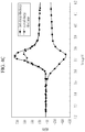
- FIG. 2A shows a charge start voltage (V s ) in 1 st differential capacity (dQ/dV)-voltage charge/discharge graphs depending on a voltage change of the half-cell manufactured in Example 2
- FIG. 3A shows a voltage (V 1 ) in a 1 st differential capacity (dQ/dV)-voltage charge/discharge graph depending on a voltage change of the half-cell manufactured in Example 2.
- V s the charge start voltage (V s ) in a 1 st differential capacity (dQ/dV)-voltage charge/discharge graph depending on the voltage change.
- V s the charge start voltage (V s ) corresponds to 3.52 V.
- the voltage (V 1 ) corresponds to about 3.56 V.
- a peak value of the differential capacity (dQ/dV)-voltage charge/discharge graph indicates a dQ/dV value at the point at which a slope of the differential capacity (dQ/dV)-voltage charge/discharge graph is changed from a positive value (+) to a negative value (-).
- the charge start voltage (V s ) may be less than or equal to 3.55 V, for example, less than or equal to 3.54 V, less than or equal to 3.53 V, or less than or equal to 3.52 V. Charging of the rechargeable lithium battery may be performed while increasing a voltage from a low voltage to a high voltage under constant current conditions.
- the voltage (V 1 ) may be less than or equal to 3.58 V, for example 3.50 V to 3.58 V, or 3.54 V to 3.58 V.
- the charge start voltage (V s ) and the voltage (V 1 ) are each involved in the form of the differential capacity (dQ/dV)-voltage (V) graph, and the charge start voltage (V s ) and the voltage (V 1 ) tend to be proportional to each other. For example, when the voltage (V 1 ) falls within the above range, the charge/discharge capacity and the charge/discharge efficiency may be improved.
- the 1 st differential capacity (dQ/dV)-voltage charge/discharge graph has at least two peak values in the range of 3.60 V to 3.85 V, and the second peak value may be larger than the first peak value. In this case, the charge/discharge capacity and the charge/discharge efficiency may be improved.
- the first peak value may be 450 mAhg -1 V -1 to 550 mAhg -1 V -1 , for example, 460 mAhg -1 V -1 to 540 mAhg -1 V -1 , 470 mAhg -1 V -1 to 530 mAhg -1 V -1 , 480 mAhg -1 V -1 to 520 mAhg -1 V -1 , or 490 mAhg -1 V -1 to 510 mAhg -1 V -1 .
- the second peak value may be 550 mAhg -1 V -1 to 650 mAhg -1 V -1 , for example, 560 mAhg -1 V -1 to 640 mAhg -1 V -1 , 570 mAhg -1 V -1 to 630 mAhg -1 V -1 , 580 mAhg -1 V -1 to 620 mAhg -1 V -1 , or 590 mAhg -1 V -1 to 610 mAhg -1 V -1 -1 .
- the shape of the 2 nd differential capacity (dQ/dV)-voltage charge/discharge graph of the differential capacity (dQ/dV)-voltage (V) closely matches the shape of the 1 st differential capacity (dQ/dV)-voltage charge/discharge graph of the differential capacity (dQ/dV)-voltage (V), and the reason is considered to be that phase structures of the positive active material remains constant even after the first charge/discharge process.
- phase stability of the positive active material may be improved, and charge/discharge capacity, charge/discharge efficiency, and cycle-life characteristics of the battery may be improved.
- At least one of the first compound and the second compound may include a core and a surface layer surrounding the core.
- the surface layer may be a region within a depth of about 200 nm, for example about 190 nm or about 180 nm from a surface of the first compound secondary particle or the second compound secondary particle, and the core may be a remaining region except the surface layer.
- the Ni atom concentration (at%) of the surface layer is higher than the Ni atom concentration (at%) of the core.
- the positive active material may be prepared through two heat-treatment processes. A large amount of residual lithium present on the surface of the secondary particles generated during the first heat-treating process is introduced into the secondary particles by reacting with the transition metal hydroxide during the second heat-treating. Thereby, it is thought that the nickel content of the positive active material surface layer is increased accordingly. As a result, since the nickel content in the surface layer, which is the region where lithium ions are most active, is relatively high, the performance of the battery may be improved.
- the positive active material may have a cation mixing of less than or equal to about 3%, for example, less than or equal to about 2.9%, less than or equal to about 2.8%, less than or equal to about 2.7%, less than or equal to about 2.6%, less than or equal to about 2.5%, or less than or equal to about 2.4%.
- the cation mixing refers to a phenomenon that Li+ (0.76 ⁇ ) and Ni 2+ (0.69 ⁇ ) having a similar ion radius exchange their sites and form a crystal.
- a divalent nickel ion (Ni 2+ ) having a similar ion radius to lithium ion may be mixed into empty space of the lithium layer having a lack of lithium caused by volatilizing a raw material of lithium salt during a high temperature firing. As a result, it may cause problems of producing a lithium nickel oxide having a non-stoichiometric composition.
- Ni 2+ mixed into the lithium layer may interrupt diffusion of lithium ions and also may greatly increase irreversibility of the ion oxidation-reduction reaction of the battery, so that capacity of the rechargeable battery may be deteriorated.
- the first heat-treating is performed at a high temperature, a rapid temperature-increasing condition, and a short time, thereby reducing the cation mixing in the above range.
- the cation mixing (%) means a ratio (%) of a portion of nickel (Ni 2+ ) ion mixed to the Li site and may be calculated by measuring by an X-ray diffraction (XRD) analysis.
- the first compound and the second compound are mixed at a weight ratio of 90 : 10 to 50 : 50, for example, 80 : 20 to 70 : 30.
- a mixture density of the positive active material may be increased, and a swelling phenomenon due to gas generation at high voltage and high temperature may be reduced.
- the second compound may have a needle-shape, a sheet-shape, or a combination thereof.
- a mixture density of the positive active material may be increased and charge/discharge capacity and charge/discharge efficiency of a battery may be improved.
- Another embodiment provides a method of preparing a positive active material.
- a method of preparing a positive active material includes mixing Compound 1A represented by Chemical Formula 1A, Compound 2A represented by Chemical Formula 2A having a smaller particle diameter than Compound 1A, and a lithium salt to prepare a mixture, first heat-treating the mixture under a rapid temperature-increasing condition to prepare a first fired product including unreacted residual lithium; and second heat-treating the first fired product.
- M 1 and M 2 are independently selected from Mn, Al, Cr, Fe, V, Mg, Ti, Zr, Nb, Mo, W, Cu, Zn, Ga, In, Sn, La, and Ce.
- desirable compositions of Ni, Co, M 1 , and M 2 may share the same range as those of the first compound and second compound represented by Chemical Formula 1 and Chemical Formula 2.
- the average particle diameters of Compound 1A and Compound 2A are respectively the same as or a little smaller than those of the first compound and the second compound.
- the lithium salt may be a lithium-containing carbonate (e.g., lithium carbonate (Li 2 CO 3 ), etc.), a hydroxide (e.g., lithium hydroxide (LiOH), etc.), a hydrate (e.g., lithium hydroxide monohydrate (LiOH- H 2 O), etc.), a nitrate (e.g., lithium nitrate (LiNO 3 ), etc.), and a chloride (e.g., lithium chloride (LiCI), etc.), and one or a mixture of two or more thereof may be used, and specifically, lithium carbonate or lithium hydroxide may be used.
- a lithium-containing carbonate e.g., lithium carbonate (Li 2 CO 3 ), etc.
- a hydroxide e.g., lithium hydroxide (LiOH), etc.
- a hydrate e.g., lithium hydroxide monohydrate (LiOH- H 2 O), etc.
- a nitrate e.
- the lithium salt and Compound 1A and Compound 2A may be mixed so that a mole ratio of Li/(Ni + Co + Mn) may be greater than or equal to about 0.99, for example about 1.00 to about 1.25.
- a large amount of unreacted lithium may remain on the surface of the first fired product obtained from the first heat-treating (at least one of the first compound and the second compound), and this residual lithium may react with at least one of Compound 1A and Compound 2A during the second heat-treating and thus form the positive active material including the first compound and the second compound.
- the Compound 1A and Compound 2A may be mixed in a weight ratio of about 90:10 to about 50:50, for example, about 80:20 to about 70:30.
- the rapid temperature-increasing condition may include a process where a temperature of the mixture is raised from about 25 °C to about 100 °C to a first heat-treating reaction temperature of about 800 °C to about 1000 °C at about 4 °C/min to about 6 °C/min.
- the first heat-treating is performed at a high temperature (about 800 °C to about 1000 °C) under an air or oxidizing gas atmosphere for a short time (about 1 hour to about 4 hours), a large amount of a nickel-based transition metal hydroxide not participating in the reaction (at least one of Compound 1A and Compound 2A) is present. Accordingly, Ni is suppressed from being changed into Ni 2+ , and accordingly, the Ni 2+ is suppressed from moving into a Li site and thus cation mixing may be prevented, and a large amount of unreacted residual lithium may be included on the surface of the nickel-based lithium transition metal oxide (at least of the first compound and the second compound).
- the oxidizing gas atmosphere indicates a gas atmosphere including oxygen in the air.
- the oxidizing gas atmosphere includes oxygen in an amount of about 20 volume% to about 40 volume%.
- an insertion height may be greater than or equal to about 5 cm, for example, in a range of about 5 cm to about 8 cm.
- a production may be increased, which is economical relative to a production cost, and in addition, the unreacted residual lithium on the surface of the first fired product may be increased and thus well formed into a positive active material in the subsequent second heat-treating.
- the first fired product is subjected to a second heat-treating.
- the second heat-treating may be performed under conditions of heating at a rate of about 5 °C/min to about 10 °C/min from about 25 °C to about 100 °C to about 700 °C to about 900 °C, maintaining at about 700 °C to about 900 °C for about 3 hours to about 10 hours, and then cooling down at a rate of about 2.5 °C/min to about 5 °C/min until about 25 °C to about 100 °C.
- the second heat-treating may be performed under an oxygen atmosphere with an oxygen amount of about 40 volume% to about 100 volume%.
- the Compound 2A may have a needle-shape, a sheet-shape, or a combination thereof.
- the second compound obtained from the method of preparing the positive active material may be maintained in the shape of Compound 2A as it is.
- a rechargeable lithium battery including a positive electrode including the positive active material; a negative electrode including a negative active material; and an electrolyte.
- the positive electrode includes a current collector and a positive active material layer formed on the current collector and including a positive active material.
- the positive active material layer may include a positive active material, and optionally a binder and a conductive material.
- the positive active material is the same as described above.
- a content of the positive active material may be about 90 wt% to about 98 wt% based on a total weight of the positive active material layer.
- the binder may include polyvinyl alcohol, carboxylmethyl cellulose, hydroxypropyl cellulose, diacetyl cellulose, polyvinyl chloride, polyvinylfluoride, polyvinylpyrrolidone, polyurethane, polytetrafluoroethylene, polyvinylidene fluoride, polyethylene, polypropylene, a styrene-butadiene rubber, an acrylated styrene butadiene rubber, an epoxy resin, nylon, and the like, but is not limited thereto.
- the conductive material may include a carbon-based material such as natural graphite, artificial graphite, carbon black, acetylene black, ketjen black, carbon fiber and the like; a metal-based material of a metal powder or a metal fiber including copper, nickel, aluminum, silver, and the like; a conductive polymer such as a polyphenylene derivative; or a mixture thereof.
- a carbon-based material such as natural graphite, artificial graphite, carbon black, acetylene black, ketjen black, carbon fiber and the like
- a metal-based material of a metal powder or a metal fiber including copper, nickel, aluminum, silver, and the like a conductive polymer such as a polyphenylene derivative; or a mixture thereof.
- each content of the binder and the conductive material may be about 1 wt% to about 5 wt% based on a total weight of the positive active material layer.
- the current collector may include an aluminum foil, a nickel foil, or a combination thereof, but is not limited thereto.
- the negative electrode includes a current collector and a negative active material layer formed on the current collector and including a negative active material.
- the negative active material may include a material that reversibly intercalates/deintercalates lithium ions, a lithium metal, a lithium metal alloy, a material capable of doping/dedoping lithium, or a transition metal oxide.
- the material that reversibly intercalates/deintercalates lithium ions may include a carbonaceous material.
- the carbonaceous material may be any generally-used carbon-based negative active material in a rechargeable lithium ion battery. Examples thereof may be crystalline carbon, amorphous carbon, or a mixture thereof.
- the crystalline carbon may be non-shaped, or sheet, flake, spherical, or fiber shaped natural graphite or artificial graphite.
- the amorphous carbon may be a soft carbon, a hard carbon, a mesophase pitch carbonization product, fired coke, and the like.
- the lithium metal alloy includes an alloy of lithium and a metal selected from Na, K, Rb, Cs, Fr, Be, Mg, Ca, Sr, Si, Sb, Pb, In, Zn, Ba, Ra, Ge, Al, and Sn.
- the material capable of doping/dedoping lithium may be Si, SiOx (0 ⁇ x ⁇ 2), a Si-Q alloy (wherein Q is an element selected from an alkali metal, an alkaline-earth metal, a Group 13 element, a Group 14 element, a Group 15 element, a Group 16 element, a transition metal, a rare earth element, and a combination thereof, but not Si), Sn, SnO 2 , a Sn-R alloy (wherein R is an element selected from an alkali metal, an alkaline-earth metal, a Group 13 element, a Group 14 element, a Group 15 element, a Group 16 element, a transition metal, a rare earth element, and a combination thereof, but not Sn), and the like.
- Q is an element selected from an alkali metal, an alkaline-earth metal, a Group 13 element, a Group 14 element, a Group 15 element, a Group 16 element, a transition metal, a rare earth element, and a
- the elements Q and R may be selected from Mg, Ca, Sr, Ba, Ra, Sc, Y, Ti, Zr, Hf, V, Nb, Ta, Cr, Mo, W, Tc, Re, Fe, Pb, Ru, Os, Rh, Ir, Pd, Pt, Cu, Ag, Au, Zn, Cd, B, Al, Ga, Sn, In, TI, Ge, P, As, Sb, Bi, S, Se, Te, Po, and a combination thereof.
- the transition metal oxide may be vanadium oxide, lithium vanadium oxide, or lithium titanium oxide.
- the negative active material may be included in an amount of about 95 wt% to about 99 wt% based on the total weight of the negative active material layer.
- the negative active material layer may include a binder, and optionally a conductive material.
- a content of the binder may be about 1 wt% to about 5 wt% based on a total weight of the negative active material layer.
- the negative active material layer further includes a conductive material, the negative active material layer includes about 90 wt% to about 98 wt% of the negative active material, about 1 wt% to about 5 wt% of the binder, and about 1 wt% to about 5 wt% of the conductive material.
- the binder improves binding properties of negative active material particles with one another and with a current collector.
- the binder includes a non-water-soluble binder, a water-soluble binder, or a combination thereof.
- the non-water-soluble binder may be selected from an ethylene propylene copolymer, polyacrylonitrile, polystyrene, polyvinylchloride, carboxylated polyvinylchloride, polyvinylfluoride, polyurethane, polytetrafluoroethylene, polyvinylidene fluoride, polyethylene, polypropylene, polyamideimide, polyimide, or a combination thereof.
- the water-soluble binder may be selected from a styrene-butadiene rubber (SBR), an acrylated styrene-butadiene rubber (ABR), an acrylonitrile-butadiene rubber, an acrylic rubber, a butyl rubber, a fluorine rubber, an ethylene oxide-containing polymer, polyvinylpyrrolidone, polyepichlorohydrine, polyphosphazene, an ethylenepropylenediene copolymer, polyvinylpyridine, chlorosulfonatedpolyethylene, a latex, a polyester resin, an acrylic resin, a phenolic resin, an epoxy resin, polyvinyl alcohol, or a combination thereof.
- SBR styrene-butadiene rubber
- ABR acrylated styrene-butadiene rubber
- ABR acrylonitrile-butadiene rubber
- acrylic rubber a butyl rubber
- a fluorine rubber an ethylene oxide
- a cellulose-based compound may be further used to provide viscosity as a thickener.
- the cellulose-based compound includes one or more of carboxymethyl cellulose, hydroxypropylmethyl cellulose, methyl cellulose, or alkali metal salts thereof.
- the alkali metals may be Na, K, or Li.
- Such a thickener may be included in an amount of about 0.1 to about 3 parts by weight based on 100 parts by weight of the negative active material.
- the conductive material may include a carbon-based material such as natural graphite, artificial graphite, carbon black, acetylene black, ketjen black, a carbon fiber, and the like; a metal-based material of a metal powder or a metal fiber including copper, nickel, aluminum silver, and the like; a conductive polymer such as a polyphenylene derivative; or a mixture thereof.
- a carbon-based material such as natural graphite, artificial graphite, carbon black, acetylene black, ketjen black, a carbon fiber, and the like
- a metal-based material of a metal powder or a metal fiber including copper, nickel, aluminum silver, and the like
- a conductive polymer such as a polyphenylene derivative
- the current collector may include at least one selected from a copper foil, a nickel foil, a stainless steel foil, a titanium foil, a nickel foam, a copper foam, a polymer substrate coated with a conductive metal, and a combination thereof.
- the electrolyte includes a non-aqueous organic solvent and a lithium salt.
- the non-aqueous organic solvent serves as a medium for transmitting ions taking part in the electrochemical reaction of a battery.
- the non-aqueous organic solvent may include dimethyl carbonate (DMC), diethyl carbonate (DEC), dipropyl carbonate (DPC), methylpropyl carbonate (MPC), ethylpropyl carbonate (EPC), methylethyl carbonate (MEC), ethylene carbonate (EC), propylene carbonate (PC), butylene carbonate (BC), methyl acetate, ethyl acetate, n-propyl acetate, dimethyl acetate, methylpropionate, ethylpropionate, decanolide, mevalonolactone, caprolactone, dibutyl ether, tetraglyme, diglyme, dimethoxyethane, 2-methyltetrahydrofuran, tetrahydrofuran, cyclohexanone, ethanol, isopropyl alcohol, nitriles such as R-CN (R may be a C2 to C20 linear, branched, or cycl
- the organic solvent may be used alone or in a mixture.
- a mixing ratio may be controlled in accordance with a desirable battery performance.
- the organic solvent may further include an aromatic hydrocarbon-based organic solvent.
- aromatic hydrocarbon-based organic solvent may be selected from benzene, fluorobenzene, 1,2-difluorobenzene, 1,3-difluorobenzene, 1,4-difluorobenzene, 1,2,3-trifluorobenzene, 1,2,4-trifluorobenzene, chlorobenzene, 1,2-dichlorobenzene, 1,3-dichlorobenzene, 1,4-dichlorobenzene, 1,2,3-trichlorobenzene, 1,2,4-trichlorobenzene, iodobenzene, 1,2-diiodobenzene, 1,3-diiodobenzene, 1,4-diiodobenzene, 1,2,3-triiodobenzene, 1,2,4-triiodobenzene, toluene, fluorotoluene, 2,
- the electrolyte may further include an additive of vinylene carbonate or an ethylene carbonate-based compound as a cycle-life improvement additive.
- Examples of the ethylene carbonate-based compound may be difluoro ethylenecarbonate, chloroethylene carbonate, dichloroethylene carbonate, bromoethylene carbonate, dibromoethylene carbonate, nitroethylene carbonate, cyanoethylene carbonate, fluoroethylene carbonate, and the like.
- the amount of the cycle-life improvement additive may be used within an appropriate range.
- the lithium salt dissolved in an organic solvent supplies a battery with lithium ions, basically operates the rechargeable lithium battery, and improves transportation of the lithium ions between a positive electrode and a negative electrode.
- lithium salt examples include at least one supporting salt selected from LiPF 6 , LiBF 4 , LiSbF 6 , LiAsF 6 , LiN(SO 2 C 2 F 5 ) 2 , Li(CF 3 SO 2 ) 2 N, LiN(SO 3 C 2 F 5 ) 2 , Li(FSO 2 ) 2 N, LiC 4 F 9 SO 3 , LiClO 4 , LiAlO 2 , LiAlCl 4 , LiN(C x F 2x+1 SO 2 )(C y F 2y+1 SO 2 ) (wherein, x and y are natural numbers, for example an integer of 1 to 20), LiCI, Lil, and LiB(C 2 O 4 ) 2 (lithium bis(oxalato) borate, LiBOB).
- LiPF 6 LiBF 4 , LiSbF 6 , LiAsF 6 , LiN(SO 2 C 2 F 5 ) 2 , Li(CF 3 SO 2 ) 2 N, LiN(SO 3 C 2
- a concentration of the lithium salt may range from about 0.1 M to about 2.0 M.
- an electrolyte may have excellent performance and lithium ion mobility due to optimal electrolyte conductivity and viscosity.
- the rechargeable lithium battery may further include a separator between the negative electrode and the positive electrode, depending on a type of the battery.
- a suitable separator material include polyethylene, polypropylene, polyvinylidene fluoride, and multi-layers thereof such as a polyethylene/polypropylene double-layered separator, a polyethylene/polypropylene/polyethylene triple-layered separator, and a polypropylene/polyethylene/polypropylene triple-layered separator.
- FIG. 1 is an exploded perspective view of a rechargeable lithium battery according to an embodiment.
- the rechargeable lithium battery according to an embodiment is illustrated as a prismatic battery but is not limited thereto and may include variously-shaped batteries such as a cylindrical battery, a pouch battery, coin-type, and the like.
- a rechargeable lithium battery 100 includes an electrode assembly 40 manufactured by winding a separator 30 disposed between a positive electrode 10 and a negative electrode 20, and a battery case 50 housing the electrode assembly 40.
- An electrolyte (not shown) may be impregnated in the positive electrode 10, the negative electrode 20, and the separator 30.
- a mixture was prepared by mixing lithium carbonate (Li 2 CO 3 ) and Ni 0.55 Co 0.25 Mn 0.20 (OH) 2 to provide Li (Ni + Co + Mn) at a mole ratio of 1.01 1.00.
- Ni 0.55 Co 0.25 Mn 0 . 20 (OH) 2 was obtained by mixing Compound 1A and Compound 2A having the same composition but different particle diameters in a weight ratio of 8 : 2.
- the prepared mixture was subjected to a first heat-treating under conditions of heating at 5 °C/min from 25 °C to 900 °C, maintaining at 900 °C for 2 hours, and then cooling at 5 °C/min until 25 °C to provide a first fired product including a first compound (Li 1.01 Ni 0.55 Co 0.25 Mn 0.20 O 2 ) and a second compound (Li 1.01 Ni 0.55 Co 0.25 Mn 0.20 O 2 ). Meanwhile, the first heat-treating process was performed under an air atmosphere in an insertion height of 5 cm.
- the first fired product was subjected to a second heat-treating under conditions of heating at 5 °C/min from 25 °C to 850 °C, maintaining at 850 °C for 10 hours, and then cooling down at 5 °C/min until 25 °C to provide a positive active material in which the first compound (LiNi 0.55 Co 0.25 Mn 0.20 O 2 ) and the second compound (LiNi 0.55 Co 0.25 Mn 0.20 O 2 ) are mixed at a weight ratio of 8 : 2. Meanwhile, the second heat-treating was performed under an oxygen (O 2 ) atmosphere.
- O 2 oxygen
- an average particle diameter (D50) of the first compound was 20 ⁇ m
- an average particle diameter (D50) of the second compound was 3 ⁇ m
- an average of the average particle diameters (D50) of the first compound and the second compound was 17 ⁇ m.
- the second compound had a shape of combining a long needle shape and a sheet shape.
- the commercial product NCM111 (LiNi 1/3 Co 1/3 Mn 1/3 , Yumi Koa Co., Ltd.) was used as the positive active material.
- the commercial product NCM523 (LiNi 0.5 Co 0.2 Mn 0.3 , Easpring) was used as the positive active material.
- a mixture was prepared by mixing lithium carbonate (Li 2 CO 3 ) and Compound 1A Ni 0.55 Co 0.25 Mn 0.20 (OH) 2 to provide Li: (Ni + Co + Mn) at a mole ratio of 1.03 : 1.
- the prepared mixture was subjected to a heat treatment under conditions of heating at 2.5 °C/min from 25 °C to 850 °C, maintaining at 850 °C for 20 hours, and then cooling down at 2.5 °C/min until 25 °C to provide a first compound (Li 1.03 Ni 0.55 Co 0.25 Mn 0.20 O 2 ). Meanwhile, the heat-treating process was performed in an insertion height of 5 cm under an air atmosphere.
- Lithium carbonate (Li 2 CO 3 ) and Compound 2A (Ni 0.55 Co 0.25 Mn 0.20 (OH) 2 ) having a combination of long needle shapes and sheet shapes are mixed to provide Li: (Ni + Co + Mn) at a mole ratio of 1.00 to 1.01 : 1, and the mixture was subjected to a heat treatment under conditions of heating at 2.5 °C/min from 25 °C to 750 °C, maintaining at 750 °C for 15 hours, and then cooling down at 5 °C/min until 25 °C to provide a second compound represented by Li 1.00 Ni 0.55 Co 0.25 Mn 0.20 O 2 . The process was performed under an air atmosphere.
- the first compound and the second compound are mixed at a weight ratio of 8 : 2, and the mixture was subjected to a third heat-treating under a condition of 400 °C to provide a positive active material including the first compound and the second compound.
- the first compound has an average particle diameter (D50) of 20 ⁇ m and the second compound has an average particle diameter (D50) of 3 ⁇ m.
- the commercial product NCM622 (LiNi 0.6 Co 0.2 Mn 0.2 , Yumi Koa Co., Ltd.) was used as the positive active material.
- the commercial product NCM701515 (LiNi 0.7 Co 0.15 Mn 0.15 , L&F Co., Ltd.) was used as the positive active material.
- the commercial product NCM811 (LiNi 0.8 Co 0.1 Mn 0.1 , Yumi Koa Co., Ltd.) was used as the positive active material.
- positive active material slurry 94 wt% of positive active material prepared in Example 1, 3 wt% of ketjen black, and 3 wt% of polyvinylidene fluoride were mixed in N-methyl pyrrolidone solvent to prepare positive active material slurry.
- the positive active material slurry was coated on an Al foil followed by drying and compressing the same to manufacture a positive electrode.
- the 2032-type a half-cell was manufactured by a conventional method using the positive electrode, a lithium metal counter electrode, and an electrolyte.
- the electrolyte was a mixed solvent (50: 50 volume ratio) of ethylene carbonate and dimethyl carbonate in which 1.0 M LiPF 6 was dissolved.
- Each 2032-type half-cell was manufactured according to the same method as Example 2, except that each positive active material prepared in Comparative Example 1 to Comparative Example 6 was used.
- the 1 st differential capacity (dQ/dV)-voltage charge/discharge graphs according to the first charge/discharge and the 2 nd differential capacity (dQ/dV)-voltage charge/discharge graphs according to the second charge/discharge were measured.
- Example 2 The 1 st differential capacity (dQ/dV)-voltage charge/discharge graphs of Example 2 and Comparative Examples 8 to 10 according to the first charge/discharge are respectively shown in FIGS. 2A and 3A (Example 2), FIGS. 2B and 3B (Comparative Example 8), FIGS. 2C and 3C (Comparative Example 9), and FIGS. 2D and 3D (Comparative Example 10).
- FIG. 4A shows the 1 st differential capacity (dQ/dV)-voltage charge/discharge graph of Example 2 according to the first charge/discharge and the 2 nd differential capacity (dQ/dV)-voltage charge/discharge graph of Example 2 according to the second charge/discharge
- FIGS. 4B , 4C , and 4D respectively show the graphs of Comparative Examples 8 to 10.
- each charge capacity, discharge capacity, and charge/discharge efficiency according to the first charge/discharge and the second charge/discharge are shown in Table 1.
- Table 1 Charge capacity (mAh/g) Discharge capacity (mAh/g) Charge/discha rge efficiency (%)
- Example 2 (NCM552520) 1 st charge/discharge 186.4 172.4 92.5 2 nd charge/discharge 172.3 172.0 99.8 Difference (1 st - 2 nd ) 14.1 0.4 - Comparative Example 8 (NCM523) 1 st charge/discharge 180.1 159.4 88.5 2 nd charge/discharge 159.3 158.8 99.7 Difference (1 st - 2 nd ) 20.8 0.6 - Comparative Example 9 (NCM552520) 1 st charge/discharge 185.3 163.7 88.3 2 nd charge/discharge 163.5 162.8 99.6 Difference (1 st - 2 nd ) 21.8 0.9 - Comparative Example 10
- Example 2 using the positive active material of Example 1 exhibited improved initial charge/discharge capacity and charge/discharge efficiency compared with the half-cells of Comparative Examples 8 to 10 respectively using the positive active materials of Comparative Examples 2 to 4.
- Example 2 exhibited a little decrease (14.1 mAh/g) of the 2 nd charge capacity relative to the 1 st charge capacity, but the half-cells of Comparative Examples 8 to 10 exhibited a relatively large decrease (18.4 mAh/g to 21.8 mAh/g), and the reason is that as for Comparative Examples 8 to 10, the positive active materials had phase structure changes during the initial charge/discharge.
- the positive active materials showed consistent tendency in terms of charge/discharge characteristics depending on a nickel content, and referring to Table 2 and FIGS. 2A to 2D , 3A to 3D , and 3E , as each nickel content of the positive active materials increases, charge start voltages (V s ) and voltages (V 1 ) thereof tend to decrease. Referring to this result and the experiment results of Comparative Examples 8 to 10 of Table 1, as the charge start voltages (V s ) and voltages (V 1 ) decreased, charge/discharge capacity and charge/discharge efficiency thereof were improved.
- Example 2 included even 55 at% of nickel but was out of the aforementioned tendency and specifically, exhibited much decreased charge start voltage (V s ) and voltage (V 1 ) compared with Comparative Examples 9 to 12 including nickel at a high content, and accordingly, charge/discharge capacity and charge/discharge efficiency of Example 2 were much improved.
- the 1 st differential capacity (dQ/dV)-voltage charge/discharge graph of the half-cell of Example 2 showed two peaks within a range of 3.60 V to 3.85 V, wherein the second peak value (differential capacity) was larger than the first peak value (differential capacity).
- the 1 st differential capacity (dQ/dV)-voltage charge/discharge graphs of the half-cells of Comparative Examples 7 to 12 showed a single peak within a range of 3.60 V to 3.85 V.
- the 1 st differential capacity (dQ/dV)-voltage charge/discharge graph and the 2 nd differential capacity (dQ/dV)-voltage charge/discharge graph of the half-cell according to Example 2 were almost the same (refer to FIG. 4A ), and the reason is that the positive active material had no phase structure change during the initial charge/discharge.
- the half-cells according to Comparative Examples 8 to 10 exhibited that the 2 nd differential capacity (dQ/dV)-voltage charge/discharge graphs changed from the 1 st differential capacity (dQ/dV)-voltage charge/discharge graphs (refer to FIGS. 4B , 4C , and 4D ), and the reason is that the positive active materials exhibited a phase structure change during the initial charge/discharge.
- phase stability of the positive active material of the half-cell according to Example 2 was improved compared with that of the positive active materials of the half-cells according to Comparative Examples 8 to 10, and accordingly, charge/discharge capacity and charge/discharge efficiency thereof were improved.
- the results of Example 2 and Comparative Examples 8 to 10 are shown in FIG. 5 .
- Example 2 exhibited excellent high temperature cycle-life characteristics compared with the half-cells according to Comparative Examples 8 to 10.
Description
- A positive active material for a rechargeable lithium battery, a method of preparing the same, and a rechargeable lithium battery including the same are disclosed.
- In order to meet down-sizing and high performance of various devices, rechargeable lithium batteries have become increasingly important in terms of high energy density as well as down-sizing and weight reduction. In addition, high capacity and high temperature stability of rechargeable lithium batteries, and stability at a high voltage become important to apply to electric vehicles and the like.
- Various positive active materials have been investigated to realize rechargeable lithium batteries for applications to the uses.
- Nickel-based lithium transition metal oxide including Ni, Co, and Mn simultaneously provides higher discharge capacity per unit weight than LiCoO2, but provides low capacity per unit volume due to a low packing density and exhibits low discharge capacity in a rechargeable lithium battery. In addition, a rechargeable lithium battery including the nickel-based lithium transition metal oxide may show deteriorated safety during operation at a high voltage.
- In particular, when a Ni content is about 33 at% to about 60 at%, charge/discharge efficiency of the rechargeable battery employing it is less than about 90%, a cation mixing value is about 5%, and the Li/transition metal mole ratio of 1.01 to 1.05. Theoretically, an ideal ratio of Li/metal (transition metal except Li) is 1.00. However, in a conventional synthesis method of a Ni-based positive active material, since Li is excessively mixed relative to the transition metal, charge/discharge efficiency of a rechargeable lithium battery employing the same may be deteriorated and a cation mixing value may be increased. Examples may be found in
EP 3 396 746 A1US 2019/067689 A1 ,US 2013/323598 A1 ,US 2012/015250 A1 ,WO 2014/205215 A2 orEP 3 647 269 A1 . - Therefore, there are increasing needs for a positive active material having an ideal layered structure and a high efficiency rechargeable lithium battery employing the same, by decreasing cation mixing of the positive active material.
- An embodiment provides a positive active material for a rechargeable lithium battery having improved phase stability due to an ideal layered structure (a structure for minimizing cation mixing).
- (Not falling under the protection scope of the present application) Another embodiment provides a method of preparing the positive active material.
- Another embodiment provides a rechargeable lithium battery having improved charge/discharge capacity, charge/discharge efficiency, and cycle-life characteristics, by including the positive active material.
- One aspect of the present disclosure refers to a positive active material for a rechargeable lithium battery that includes particles of a first compound represented by Chemical Formula 1 and particles of a second compound represented by Chemical Formula 2, wherein the particles of the first compound have an average particle diameter D50 of 15 µm to 20 µm and the particles of the second compound have an average particle diameter D50 of 2 µm to 5 µm measured by scanning electron microscopy, SEM,. The first compound and the second compound have a Ni content of 50 at% to 60 at% of the metal elements excluding Li:
[Chemical Formula 1] LiaNixCoyM1 zO2
[Chemical Formula 2] LiaNixCoyM2 zO2
- In Chemical Formula 1 and Chemical Formula 2, 0.9 ≤ a ≤ 1.05, 0.5 ≤ x ≤ 0.6, 0.05 ≤ y ≤0.35, 0.05 ≤ z ≤ 0.35, x + y + z =1, and M1 and M2 are independently at least one metal element selected from Mn, Al, Cr, Fe, V, Mg, Ti, Zr, Nb, Mo, W, Cu, Zn, Ga, In, Sn, La, and Ce.
- Further, at least one of the particles of the first compound and the particles of the second compound comprises a core and a surface layer surrounding the core and a Ni atom concentration (at%) of the metal elements except Li in the surface layer is higher than a Ni atom concentration (at%) of the metal elements except Li in the core. The surface layer may be a region corresponding to a depth of 200 nm from the surface of particles of the first compound or particles of the second compound.
- According to another embodiment, a cation mixing is less than or equal to 3%.
- According to another embodiment, the particles of the second compound have a needle-shape, a sheet-shape, or a combination thereof.
- According to another embodiment, wherein the particles of the first compound and the particles of the second compound are mixed in a weight ratio of 90 : 10 to 50 : 50.
- (Not falling under the protection scope of the present application) Another aspect of the present disclosure refers to a method of preparing a positive active material, the method comprising the steps of:
- mixing particles of Compound 1A represented by Chemical Formula 1A, particles of Compound 2A represented by Chemical Formula 2A, and a lithium salt to prepare a mixture;
- first heat-treating the mixture under a rapid temperature-increasing condition to prepare a first fired product comprising residual lithium; and
- second heat-treating the first fired product to prepare the positive active material:
[Chemical Formula 1A] NixCoyM1 z(OH)2
[Chemical Formula 2A] NixCoyM2 z (OH)2
- wherein, in Chemical Formula 1A and Chemical Formula 2A, 0.5 ≤ x ≤ 0.6, 0.05 ≤ y < 0.35, 0.05 ≤ z ≤ 0.35, x + y + z =1, and M1 and M2 are independently selected from Mn, Al, Cr, Fe, V, Mg, Ti, Zr, Nb, Mo, W, Cu, Zn, Ga, In, Sn, La, and Ce,
- wherein the particles of the first compound have an average particle diameter D50 of 15 µm to 20 µm and the particles of the second compound have an average particle diameter D50 of 2 µm to 5 µm measured by scanning electron microscopy, SEM.
- Accordign to one embodiment, the particles of Compound 1A and the particles of Compound 2A are mixed in a weight ratio of 90 : 10 to 50 : 50.
- According to another embodiment, in the mixture, a mole ratio of Li/(Ni + Co + Mn) is greater than or equal to 0.99.
- According to another embodiment, the first heat-treating comprises a process of maintaining the mixture at 800 ° C to 1000 ° C for 1 hour to 4 hours.
- Another aspect of the present disclosure refers to a rechargeable lithium battery comprising a positive electrode comprising the before mentioned positive active material, a negative electrode comprising a negative active material; and an electrolyte.
- According to one embodiment, a differential capacity (dQ/dV)-voltage charge/discharge graph of the rechargeable lithium battery satisfies Relation 1:

- The charge start voltage (Vs) of the rechargeable lithium battery may be less than or equal to 3.55 V; and/or the voltage (V1) may be less than or equal to 3.58 V, in particular may be the voltage (V1) 3.50 V to 3.58 V.
- A differential capacity (dQ/dV)-voltage charge/discharge graph may have at least two peak values in the range of 3.60 V to 3.85 V, and the second peak value may be larger than the first peak value. The first peak value may be 450 mAhg-1V-1 to 550 mAhg-1V-1 and the second peak value may be 550 mAhg-1V-1 to 650 mAhg-1V-1.
- It is possible to provide a battery in which cation mixing is reduced, and charge/discharge capacity and charge/discharge efficiency are improved.
- It is also possible to provide a battery in which unreacted residual lithium and gas generation on the surface of the positive active material are suppressed and phase stability and cycle-life characteristics are improved.
-
-
FIG. 1 is a schematic view illustrating a structure of a rechargeable lithium battery according to an embodiment. -
FIGS. 2A to 2D show charge start voltages (Vs) in 1st differential capacity (dQ/dV)-voltage charge/discharge graphs depending on voltage changes of the half-cells manufactured in Example 2 and Comparative Examples 8 to 10, respectively. -
FIGS. 3A to 3D show voltages (V1) in 1st differential capacity (dQ/dV)-voltage charge/discharge graphs depending on voltage changes of the half-cells manufactured in Example 2 and Comparative Examples 8 to 10. -
FIG. 3E shows 1st differential capacity (dQ/dV)-voltage charge/discharge graphs depending on voltage changes of the half-cells manufactured in Comparative Example 7, 8, and 10 to 12. -
FIGS. 4A to 4D show comparisons of 1st differential capacity (dQ/dV)-voltage charge/discharge graphs depending on voltage changes and 2nd differential capacity (dQ/dV)-voltage charge/discharge graphs depending on voltage changes of the half-cells manufactured in Example 2 and Comparative Examples 8 to 10. -
FIG. 5 is a graph showing high temperature cycle-life characteristics of the half-cells manufactured in Example 2 and Comparative Examples 8 to 10. - Hereinafter, embodiments of the present disclosure are described in detail. However, these embodiments are exemplary, the present disclosure is not limited thereto and the present disclosure is defined by the scope of claims.
- As used herein, when a specific definition is not otherwise provided, "first (or second) differential capacity (dQ/dV)-voltage charge/discharge graphs depending on voltage changes" refers to a graph showing the changes in differential capacity (dQ/dV) depending on voltage changes of first (or second) charging/discharging half-cells.
- As used herein, when specific definition is not otherwise provided, It will be understood that when an element such as a layer, film, region, or substrate is referred to as being "on" another element, it can be directly on the other element or intervening elements may also be present.
- An embodiment provides a positive active material for a rechargeable lithium battery that includes particles of a first compound represented by Chemical Formula 1 and particles of a second compound having a smaller particle diameter than the first compound and represented by Chemical Formula 2, wherein the first compound and the second compound have a Ni content of 50 at% to 60 at% of the metal elements excluding Li. A rechargeable lithium battery including the particles of first compound and particles of the second compound satisfies Relation 1 in a differential capacity (dQ/dV)-voltage charge/discharge graph:
[Chemical Formula 1] LiaNixCoyM1 zO2
[Chemical Formula 2] LiaNixCoyM2 zO2
- In Chemical Formula 1 and
Chemical Formula 2, 0.9 ≤ a ≤ 1.05, 0.5 ≤ x ≤ 0.6, 0.05 ≤ y ≤0.35, 0.05 ≤ z ≤ 0.35, x + y + z =1, and M1 and M2 are independently at least one metal element selected from Mn, Al, Cr, Fe, V, Mg, Ti, Zr, Nb, Mo, W, Cu, Zn, Ga, In, Sn, La, and Ce.
- In Relation 1, V1 is a voltage value at a point where the tangent meets the line dQ/dV = 0 at a value corresponding to 50% of the first peak value of the differential capacity (dQ/dV)-voltage charge/discharge graph and Vs is a charge start voltage.
- In the first compound and the second compound, a nickel content of the total metals except lithium is 50 at% to 60 at%, for example 51 at% to 59 at%, in particular 52 at% to 58 at%, most preferred 53 at% to 57 at%. Accordingly, the charge/discharge capacity, efficiency, and cycle-life characteristics of the battery may be improved.
- In general, as the content of nickel included in the positive active material increases, the charge start voltage (Vs) and the voltage (V1) of the battery tend to be lowered, and thus charge/discharge capacity and charge/discharge efficiency are improved. However, as described above, the positive active material according to the embodiment has a relatively low charge start voltage (Vs) and a voltage (V1) in spite of low nickel content, thereby improving charge/discharge capacity and charge/discharge efficiency of the battery.
- Meanwhile, in the first compound and the second compound, a mole ratio (Mn/Ni) of manganese relative to nickel may independently fall in the range of 0.36 to 0.55, for example, 0.45 to 0.55, and a mole ratio (Mn/Co) of manganese relative to cobalt may fall in the range of 0.8 to 2.0, for example, 1.25 to 2.0. Accordingly, a commercially available high nickel NCM-based positive active material has an initial charge/discharge efficiency of less than 90%, but the positive active material according to the embodiment may obtain an initial charge/discharge efficiency of greater than or equal to 92%, and it also has an advantage of reducing manufacturing process costs as less cobalt is used.
- The particles of the second compound have a smaller particle size than the particles of the first compound. More precisely, the average particle diameter (D50) of the particles of the first compound is greater than or equal to 15 µm, greater than or equal to 16 µm, or greater than or equal to 17 µm, and less than or equal to 20 µm, less than or equal to 19 µm, or less than or equal to 18 µm. The particles of the second compound have an average particle diameter (D50) of greater than or equal to 2 µm or greater than or equal to 3 µm, and less than or equal to 5 µm, or less than or equal to 4 µm. A difference in average particle diameter of the particles of the first compound and the particles of the second compound may be greater than or equal to 10 µm, greater than or equal to 11 µm, or greater than or equal to 12 µm, and less than or equal to 18 µm, less than or equal to 17 µm, or less than or equal to 16 µm. When the average particle diameters of the particles of the first compound and the particles of the second compound are each within the above ranges, an electrode mixture density may increase, and the high rate characteristics of the battery may be improved.
- Meanwhile, the particles of the first compound and the second compound may be in the form of secondary particles in which a plurality of primary particles are assembled, and the average particle diameter (D50) then means an average particle diameter (D50) of the secondary particles.
- In the present disclosure, the particle diameter is defined as the average particle diameter (D50) based on 50% of the volume cumulative amount in the particle size distribution curve. The particle diameter is measured by an electron microscopy examination using a scanning electron microscopy (SEM). In alternative, the particle diameter may be, for example, measured by a field emission scanning electron microscopy (FE-SEM), or a laser diffraction method. It may be measured by the laser diffraction method as follows. The particles to be measured are dispersed in a dispersion medium and then introduced into a commercially available laser diffraction particle size measuring apparatus (for example, MT 3000 of Microtrac), ultrasonic waves of about 28 kHz are irradiated with an output of about 60W, and an average particle diameter (D50) in 50% reference of the particle size distribution in a measuring apparatus may be calculated.
- In addition, in the present disclosure, the particle size may refer to a diameter when the particle shape is a spherical shape, and when the particle has a shape like a plate shape or a needle shape other than a spherical shape, the particle diameter may refer to the longest length of the particle.
- A differential capacity (dQ/dV)-voltage (V) charge/discharge graph of a rechargeable lithium battery including the particles of the first compound and the second compound satisfies Relation 1.

- In Relation 1, V1 is a voltage value at a point where the tangent meets the line dQ/dV = 0 at a value corresponding to 50% of the first peak value of the differential capacity (dQ/dV)-voltage charge/discharge graph and Vs is a charge start voltage. The graph is obtained using half-cells which are CC/CV-charged at 0.2 C and 4.25 V with a cut-off of 0.05 C and CC-discharged at 0.2 C with a cut-off of 3 V for the first charge/discharge.
- When the charge start voltage (Vs) and the voltage (V1) correspond to Relation 1, the charge/discharge capacity and the charge/discharge efficiency of the battery may be improved.
- Hereinafter, the charge start voltage (Vs) and the voltage (V1) of Relation 1 will be described with reference to
FIGS. 2A and3A . -
FIG. 2A shows a charge start voltage (Vs) in 1st differential capacity (dQ/dV)-voltage charge/discharge graphs depending on a voltage change of the half-cell manufactured in Example 2, andFIG. 3A shows a voltage (V1) in a 1st differential capacity (dQ/dV)-voltage charge/discharge graph depending on a voltage change of the half-cell manufactured in Example 2. - Referring to
FIG. 2A , in a 1st differential capacity (dQ/dV)-voltage charge/discharge graph depending on the voltage change, a point at which dQ/dV changes from 0 to a positive (+) value is the charge start voltage (Vs). For example, inFIG. 2A , the charge start voltage (Vs) corresponds to 3.52 V. - Referring to
FIG. 3A , in a 1st differential capacity (dQ/dV)-voltage charge/discharge graph depending on a voltage change, a point where the tangent meets line dQ/dV=0 at the point corresponding to about 50% of the first peak value is the voltage (V1). For example, inFIG. 3A , the voltage (V1) corresponds to about 3.56 V. - Meanwhile, as used herein, "a peak value of the differential capacity (dQ/dV)-voltage charge/discharge graph" indicates a dQ/dV value at the point at which a slope of the differential capacity (dQ/dV)-voltage charge/discharge graph is changed from a positive value (+) to a negative value (-).
- The charge start voltage (Vs) may be less than or equal to 3.55 V, for example, less than or equal to 3.54 V, less than or equal to 3.53 V, or less than or equal to 3.52 V. Charging of the rechargeable lithium battery may be performed while increasing a voltage from a low voltage to a high voltage under constant current conditions. When the charge start voltage (Vs) is within the above range, an area enclosed by the differential capacity (dQ/dV)-voltage charge/discharge graph and the straight line of differential capacity (dQ/dV) = 0, that is, the battery charge/discharge capacity may increase. As a result, the charge/discharge capacity and the charge/discharge efficiency may be improved.
- In the positive active material according to an embodiment, the voltage (V1) may be less than or equal to 3.58 V, for example 3.50 V to 3.58 V, or 3.54 V to 3.58 V. The charge start voltage (Vs) and the voltage (V1) are each involved in the form of the differential capacity (dQ/dV)-voltage (V) graph, and the charge start voltage (Vs) and the voltage (V1) tend to be proportional to each other. For example, when the voltage (V1) falls within the above range, the charge/discharge capacity and the charge/discharge efficiency may be improved.
- The 1st differential capacity (dQ/dV)-voltage charge/discharge graph has at least two peak values in the range of 3.60 V to 3.85 V, and the second peak value may be larger than the first peak value. In this case, the charge/discharge capacity and the charge/discharge efficiency may be improved.
- The first peak value may be 450 mAhg-1V-1 to 550 mAhg-1V-1, for example, 460 mAhg-1V-1 to 540 mAhg-1V-1, 470 mAhg-1V-1 to 530 mAhg-1V-1, 480 mAhg-1V-1 to 520 mAhg-1V-1, or 490 mAhg-1V-1 to 510 mAhg-1V-1.The second peak value may be 550 mAhg-1V-1 to 650 mAhg-1V-1, for example, 560 mAhg-1V-1 to 640 mAhg-1V-1, 570 mAhg-1V-1 to 630 mAhg-1V-1, 580 mAhg-1V-1 to 620 mAhg-1V-1, or 590 mAhg-1V-1 to 610 mAhg-1V-1.When the first peak value and the second peak value are within the ranges, charge/discharge capacity and charge/discharge efficiency may be improved.
- Meanwhile, in the half-cell including the positive active material according to the embodiment, the shape of the 2nd differential capacity (dQ/dV)-voltage charge/discharge graph of the differential capacity (dQ/dV)-voltage (V) closely matches the shape of the 1st differential capacity (dQ/dV)-voltage charge/discharge graph of the differential capacity (dQ/dV)-voltage (V), and the reason is considered to be that phase structures of the positive active material remains constant even after the first charge/discharge process. That is, due to the ideal layered structure (for minimizing the cation mixing) of the positive active material, phase stability of the positive active material may be improved, and charge/discharge capacity, charge/discharge efficiency, and cycle-life characteristics of the battery may be improved.
- At least one of the first compound and the second compound may include a core and a surface layer surrounding the core.
- The surface layer may be a region within a depth of about 200 nm, for example about 190 nm or about 180 nm from a surface of the first compound secondary particle or the second compound secondary particle, and the core may be a remaining region except the surface layer.
- In the positive active material, the Ni atom concentration (at%) of the surface layer is higher than the Ni atom concentration (at%) of the core.
- The positive active material may be prepared through two heat-treatment processes. A large amount of residual lithium present on the surface of the secondary particles generated during the first heat-treating process is introduced into the secondary particles by reacting with the transition metal hydroxide during the second heat-treating. Thereby, it is thought that the nickel content of the positive active material surface layer is increased accordingly. As a result, since the nickel content in the surface layer, which is the region where lithium ions are most active, is relatively high, the performance of the battery may be improved.
- The positive active material may have a cation mixing of less than or equal to about 3%, for example, less than or equal to about 2.9%, less than or equal to about 2.8%, less than or equal to about 2.7%, less than or equal to about 2.6%, less than or equal to about 2.5%, or less than or equal to about 2.4%.
- Meanwhile, the cation mixing refers to a phenomenon that Li+ (0.76 Å) and Ni2+ (0.69 Å) having a similar ion radius exchange their sites and form a crystal. Specifically, as nickel tends to prefer a divalent valence rather than a trivalent valence, a divalent nickel ion (Ni2+) having a similar ion radius to lithium ion may be mixed into empty space of the lithium layer having a lack of lithium caused by volatilizing a raw material of lithium salt during a high temperature firing. As a result, it may cause problems of producing a lithium nickel oxide having a non-stoichiometric composition. In addition, Ni2+ mixed into the lithium layer may interrupt diffusion of lithium ions and also may greatly increase irreversibility of the ion oxidation-reduction reaction of the battery, so that capacity of the rechargeable battery may be deteriorated. When the positive active material is prepared, the first heat-treating is performed at a high temperature, a rapid temperature-increasing condition, and a short time, thereby reducing the cation mixing in the above range.
- If the cation mixing falls within the above range, there are no problems caused by the cation mixing as described above.
- Meanwhile, the cation mixing (%) means a ratio (%) of a portion of nickel (Ni2+) ion mixed to the Li site and may be calculated by measuring by an X-ray diffraction (XRD) analysis.
- The first compound and the second compound are mixed at a weight ratio of 90 : 10 to 50 : 50, for example, 80 : 20 to 70 : 30. When the mixing ratio of the first compound and the second compound is within the above range, a mixture density of the positive active material may be increased, and a swelling phenomenon due to gas generation at high voltage and high temperature may be reduced.
- The second compound may have a needle-shape, a sheet-shape, or a combination thereof. When the second compound has the shape, a mixture density of the positive active material may be increased and charge/discharge capacity and charge/discharge efficiency of a battery may be improved.
- (Not falling under the protection scope of the present application) Another embodiment provides a method of preparing a positive active material.
- (Not falling under the protection scope of the present application) Hereinafter, the preparing method is explained in detail.
- A method of preparing a positive active material according to an embodiment includes mixing Compound 1A represented by Chemical Formula 1A, Compound 2A represented by Chemical Formula 2A having a smaller particle diameter than Compound 1A, and a lithium salt to prepare a mixture, first heat-treating the mixture under a rapid temperature-increasing condition to prepare a first fired product including unreacted residual lithium; and second heat-treating the first fired product.
[Chemical Formula 1A] NixCoyM1 z(OH)2
[Chemical Formula 2A] NixCoyM2 z(OH)2
- In Chemical Formula 1A and Chemical Formula 2A, 0.5 ≤ x ≤ 0.6, 0.05 ≤ y ≤0.35, 0.05 ≤ z ≤ 0.35, x + y + z =1, and M1 and M2 are independently selected from Mn, Al, Cr, Fe, V, Mg, Ti, Zr, Nb, Mo, W, Cu, Zn, Ga, In, Sn, La, and Ce.
- In Chemical Formula 1A and Chemical Formula 2A, desirable compositions of Ni, Co, M1, and M2 may share the same range as those of the first compound and second compound represented by Chemical Formula 1 and
Chemical Formula 2. In addition, the average particle diameters of Compound 1A and Compound 2A are respectively the same as or a little smaller than those of the first compound and the second compound. - The lithium salt may be a lithium-containing carbonate (e.g., lithium carbonate (Li2CO3), etc.), a hydroxide (e.g., lithium hydroxide (LiOH), etc.), a hydrate (e.g., lithium hydroxide monohydrate (LiOH- H2O), etc.), a nitrate (e.g., lithium nitrate (LiNO3), etc.), and a chloride (e.g., lithium chloride (LiCI), etc.), and one or a mixture of two or more thereof may be used, and specifically, lithium carbonate or lithium hydroxide may be used.
- The lithium salt and Compound 1A and Compound 2A may be mixed so that a mole ratio of Li/(Ni + Co + Mn) may be greater than or equal to about 0.99, for example about 1.00 to about 1.25. When the lithium salt and Compound 1A and Compound 2A are mixed within the mixing ratio ranges, a large amount of unreacted lithium may remain on the surface of the first fired product obtained from the first heat-treating (at least one of the first compound and the second compound), and this residual lithium may react with at least one of Compound 1A and Compound 2A during the second heat-treating and thus form the positive active material including the first compound and the second compound.
- The Compound 1A and Compound 2A may be mixed in a weight ratio of about 90:10 to about 50:50, for example, about 80:20 to about 70:30.
- The rapid temperature-increasing condition may include a process where a temperature of the mixture is raised from about 25 °C to about 100 °C to a first heat-treating reaction temperature of about 800 °C to about 1000 °C at about 4 °C/min to about 6 °C/min. By performing the rapid temperature-increasing in a short time, it may prevent the cation mixing, and the first fired product may include a large amount of unreacted residual lithium.
- Specifically, since the first heat-treating is performed at a high temperature (about 800 °C to about 1000 °C) under an air or oxidizing gas atmosphere for a short time (about 1 hour to about 4 hours), a large amount of a nickel-based transition metal hydroxide not participating in the reaction (at least one of Compound 1A and Compound 2A) is present. Accordingly, Ni is suppressed from being changed into Ni2+, and accordingly, the Ni2+ is suppressed from moving into a Li site and thus cation mixing may be prevented, and a large amount of unreacted residual lithium may be included on the surface of the nickel-based lithium transition metal oxide (at least of the first compound and the second compound).
- On the other hand, the oxidizing gas atmosphere indicates a gas atmosphere including oxygen in the air. The oxidizing gas atmosphere includes oxygen in an amount of about 20 volume% to about 40 volume%.
- In the first heat-treating, an insertion height may be greater than or equal to about 5 cm, for example, in a range of about 5 cm to about 8 cm. In this way, when the mixture is inserted into a heat-treatment equipment at the height of greater than or equal to about 5 cm during the first heat-treating, a production may be increased, which is economical relative to a production cost, and in addition, the unreacted residual lithium on the surface of the first fired product may be increased and thus well formed into a positive active material in the subsequent second heat-treating.
- Then, the first fired product is subjected to a second heat-treating.
- The second heat-treating may be performed under conditions of heating at a rate of about 5 °C/min to about 10 °C/min from about 25 °C to about 100 °C to about 700 °C to about 900 °C, maintaining at about 700 °C to about 900 °C for about 3 hours to about 10 hours, and then cooling down at a rate of about 2.5 °C/min to about 5 °C/min until about 25 °C to about 100 °C.
- The second heat-treating may be performed under an oxygen atmosphere with an oxygen amount of about 40 volume% to about 100 volume%.
- The Compound 2A may have a needle-shape, a sheet-shape, or a combination thereof. The second compound obtained from the method of preparing the positive active material may be maintained in the shape of Compound 2A as it is.
- Another embodiment provides a rechargeable lithium battery including a positive electrode including the positive active material; a negative electrode including a negative active material; and an electrolyte.
- The positive electrode includes a current collector and a positive active material layer formed on the current collector and including a positive active material.
- The positive active material layer may include a positive active material, and optionally a binder and a conductive material.
- The positive active material is the same as described above.
- In the positive active material layer, a content of the positive active material may be about 90 wt% to about 98 wt% based on a total weight of the positive active material layer.
- The binder may include polyvinyl alcohol, carboxylmethyl cellulose, hydroxypropyl cellulose, diacetyl cellulose, polyvinyl chloride, polyvinylfluoride, polyvinylpyrrolidone, polyurethane, polytetrafluoroethylene, polyvinylidene fluoride, polyethylene, polypropylene, a styrene-butadiene rubber, an acrylated styrene butadiene rubber, an epoxy resin, nylon, and the like, but is not limited thereto.
- Examples of the conductive material may include a carbon-based material such as natural graphite, artificial graphite, carbon black, acetylene black, ketjen black, carbon fiber and the like; a metal-based material of a metal powder or a metal fiber including copper, nickel, aluminum, silver, and the like; a conductive polymer such as a polyphenylene derivative; or a mixture thereof.
- Herein, each content of the binder and the conductive material may be about 1 wt% to about 5 wt% based on a total weight of the positive active material layer.
- The current collector may include an aluminum foil, a nickel foil, or a combination thereof, but is not limited thereto.
- The negative electrode includes a current collector and a negative active material layer formed on the current collector and including a negative active material.
- The negative active material may include a material that reversibly intercalates/deintercalates lithium ions, a lithium metal, a lithium metal alloy, a material capable of doping/dedoping lithium, or a transition metal oxide.
- The material that reversibly intercalates/deintercalates lithium ions may include a carbonaceous material. The carbonaceous material may be any generally-used carbon-based negative active material in a rechargeable lithium ion battery. Examples thereof may be crystalline carbon, amorphous carbon, or a mixture thereof. The crystalline carbon may be non-shaped, or sheet, flake, spherical, or fiber shaped natural graphite or artificial graphite. The amorphous carbon may be a soft carbon, a hard carbon, a mesophase pitch carbonization product, fired coke, and the like.
- The lithium metal alloy includes an alloy of lithium and a metal selected from Na, K, Rb, Cs, Fr, Be, Mg, Ca, Sr, Si, Sb, Pb, In, Zn, Ba, Ra, Ge, Al, and Sn.
- The material capable of doping/dedoping lithium may be Si, SiOx (0 < x < 2), a Si-Q alloy (wherein Q is an element selected from an alkali metal, an alkaline-earth metal, a Group 13 element, a Group 14 element, a Group 15 element, a Group 16 element, a transition metal, a rare earth element, and a combination thereof, but not Si), Sn, SnO2, a Sn-R alloy (wherein R is an element selected from an alkali metal, an alkaline-earth metal, a Group 13 element, a Group 14 element, a Group 15 element, a Group 16 element, a transition metal, a rare earth element, and a combination thereof, but not Sn), and the like. At least one of these materials may be mixed with SiO2. The elements Q and R may be selected from Mg, Ca, Sr, Ba, Ra, Sc, Y, Ti, Zr, Hf, V, Nb, Ta, Cr, Mo, W, Tc, Re, Fe, Pb, Ru, Os, Rh, Ir, Pd, Pt, Cu, Ag, Au, Zn, Cd, B, Al, Ga, Sn, In, TI, Ge, P, As, Sb, Bi, S, Se, Te, Po, and a combination thereof.
- The transition metal oxide may be vanadium oxide, lithium vanadium oxide, or lithium titanium oxide.
- In the negative active material layer, the negative active material may be included in an amount of about 95 wt% to about 99 wt% based on the total weight of the negative active material layer.
- In an embodiment, the negative active material layer may include a binder, and optionally a conductive material. In the negative active material layer, a content of the binder may be about 1 wt% to about 5 wt% based on a total weight of the negative active material layer. When the negative active material layer further includes a conductive material, the negative active material layer includes about 90 wt% to about 98 wt% of the negative active material, about 1 wt% to about 5 wt% of the binder, and about 1 wt% to about 5 wt% of the conductive material.
- The binder improves binding properties of negative active material particles with one another and with a current collector. The binder includes a non-water-soluble binder, a water-soluble binder, or a combination thereof.
- The non-water-soluble binder may be selected from an ethylene propylene copolymer, polyacrylonitrile, polystyrene, polyvinylchloride, carboxylated polyvinylchloride, polyvinylfluoride, polyurethane, polytetrafluoroethylene, polyvinylidene fluoride, polyethylene, polypropylene, polyamideimide, polyimide, or a combination thereof.
- The water-soluble binder may be selected from a styrene-butadiene rubber (SBR), an acrylated styrene-butadiene rubber (ABR), an acrylonitrile-butadiene rubber, an acrylic rubber, a butyl rubber, a fluorine rubber, an ethylene oxide-containing polymer, polyvinylpyrrolidone, polyepichlorohydrine, polyphosphazene, an ethylenepropylenediene copolymer, polyvinylpyridine, chlorosulfonatedpolyethylene, a latex, a polyester resin, an acrylic resin, a phenolic resin, an epoxy resin, polyvinyl alcohol, or a combination thereof.
- When the water-soluble binder is used as a negative electrode binder, a cellulose-based compound may be further used to provide viscosity as a thickener. The cellulose-based compound includes one or more of carboxymethyl cellulose, hydroxypropylmethyl cellulose, methyl cellulose, or alkali metal salts thereof. The alkali metals may be Na, K, or Li. Such a thickener may be included in an amount of about 0.1 to about 3 parts by weight based on 100 parts by weight of the negative active material.
- The conductive material may include a carbon-based material such as natural graphite, artificial graphite, carbon black, acetylene black, ketjen black, a carbon fiber, and the like; a metal-based material of a metal powder or a metal fiber including copper, nickel, aluminum silver, and the like; a conductive polymer such as a polyphenylene derivative; or a mixture thereof.
- The current collector may include at least one selected from a copper foil, a nickel foil, a stainless steel foil, a titanium foil, a nickel foam, a copper foam, a polymer substrate coated with a conductive metal, and a combination thereof.
- The electrolyte includes a non-aqueous organic solvent and a lithium salt.
- The non-aqueous organic solvent serves as a medium for transmitting ions taking part in the electrochemical reaction of a battery.
- The non-aqueous organic solvent may include dimethyl carbonate (DMC), diethyl carbonate (DEC), dipropyl carbonate (DPC), methylpropyl carbonate (MPC), ethylpropyl carbonate (EPC), methylethyl carbonate (MEC), ethylene carbonate (EC), propylene carbonate (PC), butylene carbonate (BC), methyl acetate, ethyl acetate, n-propyl acetate, dimethyl acetate, methylpropionate, ethylpropionate, decanolide, mevalonolactone, caprolactone, dibutyl ether, tetraglyme, diglyme, dimethoxyethane, 2-methyltetrahydrofuran, tetrahydrofuran, cyclohexanone, ethanol, isopropyl alcohol, nitriles such as R-CN (R may be a C2 to C20 linear, branched, or cyclic hydrocarbon group and R may include a double bond, an aromatic ring, or an ether bond), and the like, amides such as dimethyl formamide, and the like, dioxolanes such as 1,3-dioxolane, and the like, sulfolanes, and the like.
- The organic solvent may be used alone or in a mixture. When the organic solvent is used in a mixture, a mixing ratio may be controlled in accordance with a desirable battery performance.
- In addition, the organic solvent may further include an aromatic hydrocarbon-based organic solvent. Specific examples of the aromatic hydrocarbon-based organic solvent may be selected from benzene, fluorobenzene, 1,2-difluorobenzene, 1,3-difluorobenzene, 1,4-difluorobenzene, 1,2,3-trifluorobenzene, 1,2,4-trifluorobenzene, chlorobenzene, 1,2-dichlorobenzene, 1,3-dichlorobenzene, 1,4-dichlorobenzene, 1,2,3-trichlorobenzene, 1,2,4-trichlorobenzene, iodobenzene, 1,2-diiodobenzene, 1,3-diiodobenzene, 1,4-diiodobenzene, 1,2,3-triiodobenzene, 1,2,4-triiodobenzene, toluene, fluorotoluene, 2,3-difluorotoluene, 2,4-difluorotoluene, 2,5-difluorotoluene, 2,3,4-trifluorotoluene, 2,3,5-trifluorotoluene, chlorotoluene, 2,3-dichlorotoluene, 2,4-dichlorotoluene, 2,5-dichlorotoluene, 2,3,4-trichlorotoluene, 2,3,5-trichlorotoluene, iodotoluene, 2,3-diiodotoluene, 2,4-diiodotoluene, 2,5-diiodotoluene, 2,3,4-triiodotoluene, 2,3,5-triiodotoluene, xylene, and a combination thereof.
- The electrolyte may further include an additive of vinylene carbonate or an ethylene carbonate-based compound as a cycle-life improvement additive.
- Examples of the ethylene carbonate-based compound may be difluoro ethylenecarbonate, chloroethylene carbonate, dichloroethylene carbonate, bromoethylene carbonate, dibromoethylene carbonate, nitroethylene carbonate, cyanoethylene carbonate, fluoroethylene carbonate, and the like. The amount of the cycle-life improvement additive may be used within an appropriate range.
- The lithium salt dissolved in an organic solvent supplies a battery with lithium ions, basically operates the rechargeable lithium battery, and improves transportation of the lithium ions between a positive electrode and a negative electrode.
- Examples of the lithium salt include at least one supporting salt selected from LiPF6, LiBF4, LiSbF6, LiAsF6, LiN(SO2C2F5)2, Li(CF3SO2)2N, LiN(SO3C2F5)2, Li(FSO2)2N, LiC4F9SO3, LiClO4, LiAlO2, LiAlCl4, LiN(CxF2x+1SO2)(CyF2y+1SO2) (wherein, x and y are natural numbers, for example an integer of 1 to 20), LiCI, Lil, and LiB(C2O4)2 (lithium bis(oxalato) borate, LiBOB).
- A concentration of the lithium salt may range from about 0.1 M to about 2.0 M. When the lithium salt is included at the above concentration range, an electrolyte may have excellent performance and lithium ion mobility due to optimal electrolyte conductivity and viscosity.
- The rechargeable lithium battery may further include a separator between the negative electrode and the positive electrode, depending on a type of the battery. Examples of a suitable separator material include polyethylene, polypropylene, polyvinylidene fluoride, and multi-layers thereof such as a polyethylene/polypropylene double-layered separator, a polyethylene/polypropylene/polyethylene triple-layered separator, and a polypropylene/polyethylene/polypropylene triple-layered separator.
-
FIG. 1 is an exploded perspective view of a rechargeable lithium battery according to an embodiment. The rechargeable lithium battery according to an embodiment is illustrated as a prismatic battery but is not limited thereto and may include variously-shaped batteries such as a cylindrical battery, a pouch battery, coin-type, and the like. - Referring to
FIG. 1 , arechargeable lithium battery 100 according to an embodiment includes anelectrode assembly 40 manufactured by winding aseparator 30 disposed between apositive electrode 10 and anegative electrode 20, and abattery case 50 housing theelectrode assembly 40. An electrolyte (not shown) may be impregnated in thepositive electrode 10, thenegative electrode 20, and theseparator 30. - Hereinafter, examples and comparative examples are described. However, the following examples are merely examples and the present disclosure is not limited thereto.
- A mixture was prepared by mixing lithium carbonate (Li2CO3) and Ni0.55Co0.25Mn0.20(OH)2 to provide Li (Ni + Co + Mn) at a mole ratio of 1.01 1.00. Herein, Ni0.55Co0.25Mn0.20(OH)2 was obtained by mixing Compound 1A and Compound 2A having the same composition but different particle diameters in a weight ratio of 8 : 2.
- The prepared mixture was subjected to a first heat-treating under conditions of heating at 5 °C/min from 25 °C to 900 °C, maintaining at 900 °C for 2 hours, and then cooling at 5 °C/min until 25 °C to provide a first fired product including a first compound (Li1.01Ni0.55Co0.25Mn0.20O2) and a second compound (Li1.01Ni0.55Co0.25Mn0.20O2). Meanwhile, the first heat-treating process was performed under an air atmosphere in an insertion height of 5 cm.
- The first fired product was subjected to a second heat-treating under conditions of heating at 5 °C/min from 25 °C to 850 °C, maintaining at 850 °C for 10 hours, and then cooling down at 5 °C/min until 25 °C to provide a positive active material in which the first compound (LiNi0.55Co0.25Mn0.20O2) and the second compound (LiNi0.55Co0.25Mn0.20O2) are mixed at a weight ratio of 8 : 2. Meanwhile, the second heat-treating was performed under an oxygen (O2) atmosphere.
- In this case, an average particle diameter (D50) of the first compound was 20 µm, an average particle diameter (D50) of the second compound was 3 µm, and an average of the average particle diameters (D50) of the first compound and the second compound was 17 µm. Meanwhile, the second compound had a shape of combining a long needle shape and a sheet shape.
- The commercial product NCM111 (LiNi1/3Co1/3Mn1/3, Yumi Koa Co., Ltd.) was used as the positive active material.
- The commercial product NCM523 (LiNi0.5Co0.2Mn0.3, Easpring) was used as the positive active material.
- A mixture was prepared by mixing lithium carbonate (Li2CO3) and Compound 1A Ni0.55Co0.25Mn0.20(OH)2 to provide Li: (Ni + Co + Mn) at a mole ratio of 1.03 : 1.
- The prepared mixture was subjected to a heat treatment under conditions of heating at 2.5 °C/min from 25 °C to 850 °C, maintaining at 850 °C for 20 hours, and then cooling down at 2.5 °C/min until 25 °C to provide a first compound (Li1.03Ni0.55Co0.25Mn0.20O2). Meanwhile, the heat-treating process was performed in an insertion height of 5 cm under an air atmosphere.
- Lithium carbonate (Li2CO3) and Compound 2A (Ni0.55Co0.25Mn0.20(OH)2) having a combination of long needle shapes and sheet shapes are mixed to provide Li: (Ni + Co + Mn) at a mole ratio of 1.00 to 1.01 : 1, and the mixture was subjected to a heat treatment under conditions of heating at 2.5 °C/min from 25 °C to 750 °C, maintaining at 750 °C for 15 hours, and then cooling down at 5 °C/min until 25 °C to provide a second compound represented by Li1.00Ni0.55Co0.25Mn0.20O2. The process was performed under an air atmosphere.
- The first compound and the second compound are mixed at a weight ratio of 8 : 2, and the mixture was subjected to a third heat-treating under a condition of 400 °C to provide a positive active material including the first compound and the second compound.
- Herein, the first compound has an average particle diameter (D50) of 20 µm and the second compound has an average particle diameter (D50) of 3 µm.
- The commercial product NCM622 (LiNi0.6Co0.2Mn0.2, Yumi Koa Co., Ltd.) was used as the positive active material.
- The commercial product NCM701515 (LiNi0.7Co0.15Mn0.15, L&F Co., Ltd.) was used as the positive active material.
- The commercial product NCM811 (LiNi0.8Co0.1Mn0.1, Yumi Koa Co., Ltd.) was used as the positive active material.
- 94 wt% of positive active material prepared in Example 1, 3 wt% of ketjen black, and 3 wt% of polyvinylidene fluoride were mixed in N-methyl pyrrolidone solvent to prepare positive active material slurry. The positive active material slurry was coated on an Al foil followed by drying and compressing the same to manufacture a positive electrode. The 2032-type a half-cell was manufactured by a conventional method using the positive electrode, a lithium metal counter electrode, and an electrolyte. The electrolyte was a mixed solvent (50: 50 volume ratio) of ethylene carbonate and dimethyl carbonate in which 1.0 M LiPF6 was dissolved.
- Each 2032-type half-cell was manufactured according to the same method as Example 2, except that each positive active material prepared in Comparative Example 1 to Comparative Example 6 was used.
- The half-cells according to Example 2 and Comparative Examples 7 to 12 were CC/CV-charged at 0.2 C and 4.25 V with a cut-off of 0.05 C and CC-discharged at 0.2 C with a cut-off of 3 V for the first charge/discharge (1C = 180 mAh/g), and subsequently, the second charge/discharge were performed in the same method as the first charge/discharge.
- The 1st differential capacity (dQ/dV)-voltage charge/discharge graphs according to the first charge/discharge and the 2nd differential capacity (dQ/dV)-voltage charge/discharge graphs according to the second charge/discharge were measured.
- The 1st differential capacity (dQ/dV)-voltage charge/discharge graphs of Example 2 and Comparative Examples 8 to 10 according to the first charge/discharge are respectively shown in
FIGS. 2A and3A (Example 2),FIGS. 2B and3B (Comparative Example 8),FIGS. 2C and3C (Comparative Example 9), andFIGS. 2D and3D (Comparative Example 10). - In addition, the 1st differential capacity (dQ/dV)-voltage charge/discharge graphs according to Comparative Examples 7, 8, and 10 to 12 are also shown in
FIG. 3E . - In addition,
FIG. 4A shows the 1st differential capacity (dQ/dV)-voltage charge/discharge graph of Example 2 according to the first charge/discharge and the 2nd differential capacity (dQ/dV)-voltage charge/discharge graph of Example 2 according to the second charge/discharge, andFIGS. 4B ,4C , and4D respectively show the graphs of Comparative Examples 8 to 10. - In addition, each charge capacity, discharge capacity, and charge/discharge efficiency according to the first charge/discharge and the second charge/discharge are shown in Table 1.
(Table 1) Charge capacity (mAh/g) Discharge capacity (mAh/g) Charge/discha rge efficiency (%) Example 2 (NCM552520) 1st charge/discharge 186.4 172.4 92.5 2nd charge/discharge 172.3 172.0 99.8 Difference (1st - 2nd) 14.1 0.4 - Comparative Example 8 (NCM523) 1st charge/discharge 180.1 159.4 88.5 2nd charge/discharge 159.3 158.8 99.7 Difference (1st - 2nd) 20.8 0.6 - Comparative Example 9 (NCM552520) 1st charge/discharge 185.3 163.7 88.3 2nd charge/discharge 163.5 162.8 99.6 Difference (1st - 2nd) 21.8 0.9 - Comparative Example 10 1st charge/discharge 186.1 167.9 90.2 2nd charge/discharge 167.7 167.2 99.7 (NCM622) Difference (1st - 2nd) 18.4 0.7 - - As shown in Table 1, the half-cell of Example 2 using the positive active material of Example 1 exhibited improved initial charge/discharge capacity and charge/discharge efficiency compared with the half-cells of Comparative Examples 8 to 10 respectively using the positive active materials of Comparative Examples 2 to 4.
- In addition, the half-cell of Example 2 exhibited a little decrease (14.1 mAh/g) of the 2nd charge capacity relative to the 1st charge capacity, but the half-cells of Comparative Examples 8 to 10 exhibited a relatively large decrease (18.4 mAh/g to 21.8 mAh/g), and the reason is that as for Comparative Examples 8 to 10, the positive active materials had phase structure changes during the initial charge/discharge.
- Evaluation Example 2: 1st Differential Capacity (dQ/dV)-Voltage Charge/Discharge Graph The 1st differential capacity (dQ/dV)-voltage charge/discharge graphs of the half-cells according to Example 2 and Comparative Examples 7 to 12 were analyzed, and charge start voltages (Vs) and voltages (V1) thereof are shown in Table 2.
(Table 2) Charge start voltage (Vs) (Volt) Voltage (V1) (Volt) Comparative Example 7 (NCM111) 3.63 3.65 Comparative Example 8 (NCM523) 3.62 3.66 Example 2 (NCM552520) 3.52 3.56 Comparative Example 9 (NCM552520) 3.59 3.62 Comparative Example 10 (NCM622) 3.59 3.63 Comparative Example 11 (NCM701515) 3.58 3.62 Comparative Example 12 (NCM811) 3.60 3.65 - The positive active materials showed consistent tendency in terms of charge/discharge characteristics depending on a nickel content, and referring to Table 2 and
FIGS. 2A to 2D ,3A to 3D , and3E , as each nickel content of the positive active materials increases, charge start voltages (Vs) and voltages (V1) thereof tend to decrease. Referring to this result and the experiment results of Comparative Examples 8 to 10 of Table 1, as the charge start voltages (Vs) and voltages (V1) decreased, charge/discharge capacity and charge/discharge efficiency thereof were improved. - However, the half-cell of Example 2 included even 55 at% of nickel but was out of the aforementioned tendency and specifically, exhibited much decreased charge start voltage (Vs) and voltage (V1) compared with Comparative Examples 9 to 12 including nickel at a high content, and accordingly, charge/discharge capacity and charge/discharge efficiency of Example 2 were much improved.
- On the other hand, referring to
FIGS. 2A to 2D , the 1st differential capacity (dQ/dV)-voltage charge/discharge graph of the half-cell of Example 2 showed two peaks within a range of 3.60 V to 3.85 V, wherein the second peak value (differential capacity) was larger than the first peak value (differential capacity). On the other hand, the 1st differential capacity (dQ/dV)-voltage charge/discharge graphs of the half-cells of Comparative Examples 7 to 12 showed a single peak within a range of 3.60 V to 3.85 V. - Referring to
FIGS. 4A to 4D , the 1st differential capacity (dQ/dV)-voltage charge/discharge graph and the 2nd differential capacity (dQ/dV)-voltage charge/discharge graph of the half-cell according to Example 2 were almost the same (refer toFIG. 4A ), and the reason is that the positive active material had no phase structure change during the initial charge/discharge. On the contrary, the half-cells according to Comparative Examples 8 to 10 exhibited that the 2nd differential capacity (dQ/dV)-voltage charge/discharge graphs changed from the 1st differential capacity (dQ/dV)-voltage charge/discharge graphs (refer toFIGS. 4B ,4C , and4D ), and the reason is that the positive active materials exhibited a phase structure change during the initial charge/discharge. - Accordingly, phase stability of the positive active material of the half-cell according to Example 2 was improved compared with that of the positive active materials of the half-cells according to Comparative Examples 8 to 10, and accordingly, charge/discharge capacity and charge/discharge efficiency thereof were improved.
- The half-cells of Example 2 and Comparative Examples 7 to 12 were charged at a constant current-constant voltage and 1.0 C (1 C = 180 mA/g) under a cut-off condition of 4.25 V and 0.05 C at a high temperature of 45° C and discharged at a constant current and 1.0 C under a cut-off condition of 3.0 V, and this charge/discharge were 70 times repeated to measure discharge capacity. A ratio of discharge capacity at each cycle relative to the 1st discharge capacity was obtained. The results of Example 2 and Comparative Examples 8 to 10 are shown in
FIG. 5 . - Referring to
FIG. 5 , the half-cell of Example 2 exhibited excellent high temperature cycle-life characteristics compared with the half-cells according to Comparative Examples 8 to 10.
Claims (6)
- A positive active material for a rechargeable lithium battery, comprising particles of a first compound represented by Chemical Formula 1 and particles of a second compound represented by Chemical Formula 2, wherein the particles of the first compound have an average particle diameter D50 of 15 µm to 20 µm and the particles of the second compound have an average particle diameter D50 of 2 µm to 5 µm measured by scanning electron microscopy, SEM,wherein the first compound and the second compound have a Ni content of 50 at% to 60 at% of the metal elements excluding Li:
[Chemical Formula 1] LiaNixCoyM1 zO2
[Chemical Formula 2] LiaNixCoyM2 zO2
wherein, in Chemical Formula 1 and Chemical Formula 2, 0.9 ≤ a ≤ 1.05, 0.5 ≤ x ≤ 0.6, 0.05 ≤ y ≤0.35, 0.05 ≤ z ≤ 0.35, x + y + z =1, and M1 and M2 are independently at least one metal element selected from Mn, Al, Cr, Fe, V, Mg, Ti, Zr, Nb, Mo, W, Cu, Zn, Ga, In, Sn, La, and Ce,wherein at least one of the particles of the first compound and the particles of the second compound comprises a core and a surface layer surrounding the core and a Ni atom concentration (at%) of the metal elements except Li in the surface layer is higher than a Ni atom concentration (at%) of the metal elements except Li in the core. - The positive active material of claim 1, wherein the surface layer is a region corresponding to a depth of 200 nm from the surface of particles of the first compound or particles of the second compound.
- The positive active material of any one of the preceding claims, wherein a cation mixing is less than or equal to 3%.
- The positive active material of claim 1, wherein the particles of the second compound have a needle-shape, a sheet-shape, or a combination thereof.
- The positive active material of claim 1, wherein the particles of the first compound and the particles of the second compound are mixed in a weight ratio of 90 : 10 to 50 : 50.
- A rechargeable lithium battery, comprisinga positive electrode comprising a positive active material of any one of claims 1 - 5;a negative electrode comprising a negative active material; andan electrolyte.
Priority Applications (1)
| Application Number | Priority Date | Filing Date | Title |
|---|---|---|---|
| PL20161073T PL3706208T3 (en) | 2019-03-05 | 2020-03-05 | Positive active material for rechargeable lithium battery, method of preparing the same and rechargeable lithium battery including the same |
Applications Claiming Priority (2)
| Application Number | Priority Date | Filing Date | Title |
|---|---|---|---|
| KR20190025305 | 2019-03-05 | ||
| KR1020200027096A KR102314085B1 (en) | 2019-03-05 | 2020-03-04 | Positive active material for rechargeable lithium battery, method of preparing the same and rechargeable lithium battery including the same |
Publications (2)
| Publication Number | Publication Date |
|---|---|
| EP3706208A1 EP3706208A1 (en) | 2020-09-09 |
| EP3706208B1 true EP3706208B1 (en) | 2021-09-08 |
Family
ID=69770708
Family Applications (1)
| Application Number | Title | Priority Date | Filing Date |
|---|---|---|---|
| EP20161073.0A Active EP3706208B1 (en) | 2019-03-05 | 2020-03-05 | Positive active material for rechargeable lithium battery, method of preparing the same and rechargeable lithium battery including the same |
Country Status (5)
| Country | Link |
|---|---|
| US (1) | US11552293B2 (en) |
| EP (1) | EP3706208B1 (en) |
| CN (1) | CN111668462B (en) |
| HU (1) | HUE056994T2 (en) |
| PL (1) | PL3706208T3 (en) |
Families Citing this family (2)
| Publication number | Priority date | Publication date | Assignee | Title |
|---|---|---|---|---|
| KR102255905B1 (en) * | 2019-08-02 | 2021-05-24 | 삼성에스디아이 주식회사 | Positive electrode active material for rechargeable lithium battery, method of preparing the same, positive electrode for rechargeable lithium battery including the same and rechargeable lithium battery including the same |
| CN113839109A (en) * | 2021-08-17 | 2021-12-24 | 天能帅福得能源股份有限公司 | Method for rapidly grading capacity of lithium ion battery |
Family Cites Families (20)
| Publication number | Priority date | Publication date | Assignee | Title |
|---|---|---|---|---|
| CN101752558A (en) | 2008-12-22 | 2010-06-23 | 深圳市比克电池有限公司 | Lithium ion battery anode material and preparation method thereof |
| WO2010113512A1 (en) | 2009-04-03 | 2010-10-07 | パナソニック株式会社 | Positive electrode active material for lithium ion secondary battery, method for producing same, and lithium ion secondary battery |
| KR101286761B1 (en) | 2010-06-01 | 2013-07-16 | 주식회사 엘앤에프신소재 | Precursor of transition metal compound, lithium transition compound using the same, positive active material including the lithium transition compound and lithium ion secondary battery including the positive active material |
| JP6032457B2 (en) | 2012-02-03 | 2016-11-30 | 日産自動車株式会社 | Solid solution lithium-containing transition metal oxide and lithium ion secondary battery |
| WO2013137509A1 (en) | 2012-03-13 | 2013-09-19 | 주식회사 엘앤에프신소재 | Method for manufacturing anode active material for lithium secondary battery, anode active material for lithium secondary battery, and lithium secondary battery |
| TWI549336B (en) * | 2012-06-01 | 2016-09-11 | 輔仁大學學校財團法人輔仁大學 | Lithium nickel cobalt manganese cathode material powder |
| WO2014104759A1 (en) | 2012-12-26 | 2014-07-03 | 한양대학교 산학협력단 | Cathode active material for lithium secondary batteries |
| SI3011619T1 (en) | 2013-06-21 | 2018-10-30 | Cabot Corporation | Active materials for lithium ion batteries |
| KR101785262B1 (en) | 2013-07-08 | 2017-10-16 | 삼성에스디아이 주식회사 | Positive electrode active material, preparing method thereof, positive electrode including the same, and lithium secondary battery employing the positive electrode |
| KR20150099219A (en) | 2014-02-21 | 2015-08-31 | 삼성전자주식회사 | Positive active material, lithium battery containing the same, and method of manufacturing the positive active material |
| JP6369126B2 (en) | 2014-05-21 | 2018-08-08 | 戸田工業株式会社 | Positive electrode active material powder for non-aqueous electrolyte secondary battery, method for producing the same, and non-aqueous electrolyte secondary battery |
| KR102486526B1 (en) | 2015-09-10 | 2023-01-09 | 에스케이온 주식회사 | Lithium secondary battery |
| KR102101006B1 (en) | 2015-12-10 | 2020-04-14 | 주식회사 엘지화학 | Positive electrode for secondary battery and secondary battery comprising the same |
| JP6631320B2 (en) | 2016-02-29 | 2020-01-15 | 住友金属鉱山株式会社 | Nickel composite hydroxide, method for producing the same, positive electrode active material for non-aqueous electrolyte secondary battery, method for producing the same, and non-aqueous electrolyte secondary battery |
| KR102124950B1 (en) | 2016-11-23 | 2020-06-22 | 주식회사 엘지화학 | Positive electrode for secondary battery, method for preparing the same, and secondary battery comprising the same |
| KR102448302B1 (en) | 2017-04-28 | 2022-09-29 | 삼성전자주식회사 | Composite cathode active material, Cathode and Lithium battery containing composite cathode active material and Preparation method thereof |
| CN107611371A (en) | 2017-08-17 | 2018-01-19 | 格林美(无锡)能源材料有限公司 | A kind of high circulation and constitutionally stable ternary material preparation method |
| US11081693B2 (en) | 2017-08-30 | 2021-08-03 | Samsung Electronics Co., Ltd. | Composite cathode active material, method of preparing the same, and cathode and lithium battery including the composite cathode active material |
| KR102182358B1 (en) | 2018-11-02 | 2020-11-24 | 삼성에스디아이 주식회사 | Positive electrode for rechargeable lithium battery, method of preparing the same and rechargeable lithium battery including the same |
| KR102263998B1 (en) | 2018-11-02 | 2021-06-11 | 삼성에스디아이 주식회사 | Positive active material for rechargeable lithium battery, method of preparing same and rechargeable lithium battery including same |
-
2020
- 2020-03-04 US US16/809,460 patent/US11552293B2/en active Active
- 2020-03-05 CN CN202010146504.XA patent/CN111668462B/en active Active
- 2020-03-05 EP EP20161073.0A patent/EP3706208B1/en active Active
- 2020-03-05 PL PL20161073T patent/PL3706208T3/en unknown
- 2020-03-05 HU HUE20161073A patent/HUE056994T2/en unknown
Also Published As
| Publication number | Publication date |
|---|---|
| HUE056994T2 (en) | 2022-04-28 |
| EP3706208A1 (en) | 2020-09-09 |
| US20200287215A1 (en) | 2020-09-10 |
| PL3706208T3 (en) | 2022-01-24 |
| CN111668462A (en) | 2020-09-15 |
| CN111668462B (en) | 2023-11-17 |
| US11552293B2 (en) | 2023-01-10 |
Similar Documents
| Publication | Publication Date | Title |
|---|---|---|
| EP3647269B1 (en) | Positive active material for rechargeable lithium battery, method of preparing the same and rechargeable lithium battery including the same | |
| EP3708542A1 (en) | Positive active material for rechargeable lithium battery, method of preparing the same and rechargeable lithium battery including the same | |
| EP2420475A1 (en) | Negative electrode active material for rechargeable lithium battery, method of preparing same, and rechargeable lithium battery including same | |
| EP3647270B1 (en) | Positive active material for rechargeable lithium battery, method of preparing the same and rechargeable lithium battery including the same | |
| KR102358675B1 (en) | Method of positive active material for rechargeable lithium battery | |
| EP3249721A1 (en) | Positive electrode for rechargeable lithium battery and rechargeable lithium battery including same | |
| EP3703162B1 (en) | Negative active material composite for rechargeable lithium battery, method of preparing the same, negative electrode including the same, and rechargeable lithium battery including the same | |
| KR20120117526A (en) | Method for manufacturing positive active material for rechargeable lithium battery and rechargeable lithium battery using the same | |
| EP3817105A1 (en) | Positive active material for rechargeable lithium battery, method of preparing the same, and rechargeable lithium battery including the same | |
| EP3706208B1 (en) | Positive active material for rechargeable lithium battery, method of preparing the same and rechargeable lithium battery including the same | |
| EP3486977B1 (en) | Positive electrode for rechargeable lithium battery, rechargeable lithium battery including same and battery module | |
| KR102085247B1 (en) | Positive active material for rechargeable lithium battery, method of preparing the same, and rechargeable lithium battery including the same | |
| KR101673178B1 (en) | Positive active material for rechargeable lithium battery, method of preparing the same, and rechargeable lithium battery including the same | |
| KR20160093817A (en) | Positive active material for rechargeable lithium battery, method of preparing the same, and rechargeable lithium battery including the same | |
| KR20150093056A (en) | Positive active material for rechargeable lithium battery, method of preparing same, and rechargeable lithium battery including same | |
| KR102255905B1 (en) | Positive electrode active material for rechargeable lithium battery, method of preparing the same, positive electrode for rechargeable lithium battery including the same and rechargeable lithium battery including the same | |
| KR20170133949A (en) | Positive active material for rechargeable lithium battery and rechargeable lithium battery including same | |
| KR102314085B1 (en) | Positive active material for rechargeable lithium battery, method of preparing the same and rechargeable lithium battery including the same | |
| KR20200124515A (en) | Positive electrode active material for rechargeable lithium battery, method of preparing the same and rechargeable lithium battery including the same | |
| EP3550655A2 (en) | Lithium secondary battery |
Legal Events
| Date | Code | Title | Description |
|---|---|---|---|
| PUAI | Public reference made under article 153(3) epc to a published international application that has entered the european phase |
Free format text: ORIGINAL CODE: 0009012 |
|
| STAA | Information on the status of an ep patent application or granted ep patent |
Free format text: STATUS: REQUEST FOR EXAMINATION WAS MADE |
|
| 17P | Request for examination filed |
Effective date: 20200305 |
|
| AK | Designated contracting states |
Kind code of ref document: A1 Designated state(s): AL AT BE BG CH CY CZ DE DK EE ES FI FR GB GR HR HU IE IS IT LI LT LU LV MC MK MT NL NO PL PT RO RS SE SI SK SM TR |
|
| AX | Request for extension of the european patent |
Extension state: BA ME |
|
| GRAP | Despatch of communication of intention to grant a patent |
Free format text: ORIGINAL CODE: EPIDOSNIGR1 |
|
| STAA | Information on the status of an ep patent application or granted ep patent |
Free format text: STATUS: GRANT OF PATENT IS INTENDED |
|
| INTG | Intention to grant announced |
Effective date: 20210617 |
|
| GRAS | Grant fee paid |
Free format text: ORIGINAL CODE: EPIDOSNIGR3 |
|
| GRAA | (expected) grant |
Free format text: ORIGINAL CODE: 0009210 |
|
| STAA | Information on the status of an ep patent application or granted ep patent |
Free format text: STATUS: THE PATENT HAS BEEN GRANTED |
|
| AK | Designated contracting states |
Kind code of ref document: B1 Designated state(s): AL AT BE BG CH CY CZ DE DK EE ES FI FR GB GR HR HU IE IS IT LI LT LU LV MC MK MT NL NO PL PT RO RS SE SI SK SM TR |
|
| REG | Reference to a national code |
Ref country code: GB Ref legal event code: FG4D |
|
| REG | Reference to a national code |
Ref country code: CH Ref legal event code: EP Ref country code: AT Ref legal event code: REF Ref document number: 1429376 Country of ref document: AT Kind code of ref document: T Effective date: 20210915 |
|
| REG | Reference to a national code |
Ref country code: IE Ref legal event code: FG4D |
|
| REG | Reference to a national code |
Ref country code: DE Ref legal event code: R096 Ref document number: 602020000496 Country of ref document: DE |
|
| REG | Reference to a national code |
Ref country code: SE Ref legal event code: TRGR |
|
| REG | Reference to a national code |
Ref country code: LT Ref legal event code: MG9D |
|
| REG | Reference to a national code |
Ref country code: NL Ref legal event code: MP Effective date: 20210908 |
|
| PG25 | Lapsed in a contracting state [announced via postgrant information from national office to epo] |
Ref country code: RS Free format text: LAPSE BECAUSE OF FAILURE TO SUBMIT A TRANSLATION OF THE DESCRIPTION OR TO PAY THE FEE WITHIN THE PRESCRIBED TIME-LIMIT Effective date: 20210908 Ref country code: ES Free format text: LAPSE BECAUSE OF FAILURE TO SUBMIT A TRANSLATION OF THE DESCRIPTION OR TO PAY THE FEE WITHIN THE PRESCRIBED TIME-LIMIT Effective date: 20210908 Ref country code: BG Free format text: LAPSE BECAUSE OF FAILURE TO SUBMIT A TRANSLATION OF THE DESCRIPTION OR TO PAY THE FEE WITHIN THE PRESCRIBED TIME-LIMIT Effective date: 20211208 Ref country code: LT Free format text: LAPSE BECAUSE OF FAILURE TO SUBMIT A TRANSLATION OF THE DESCRIPTION OR TO PAY THE FEE WITHIN THE PRESCRIBED TIME-LIMIT Effective date: 20210908 Ref country code: NO Free format text: LAPSE BECAUSE OF FAILURE TO SUBMIT A TRANSLATION OF THE DESCRIPTION OR TO PAY THE FEE WITHIN THE PRESCRIBED TIME-LIMIT Effective date: 20211208 Ref country code: HR Free format text: LAPSE BECAUSE OF FAILURE TO SUBMIT A TRANSLATION OF THE DESCRIPTION OR TO PAY THE FEE WITHIN THE PRESCRIBED TIME-LIMIT Effective date: 20210908 Ref country code: FI Free format text: LAPSE BECAUSE OF FAILURE TO SUBMIT A TRANSLATION OF THE DESCRIPTION OR TO PAY THE FEE WITHIN THE PRESCRIBED TIME-LIMIT Effective date: 20210908 |
|
| REG | Reference to a national code |
Ref country code: AT Ref legal event code: MK05 Ref document number: 1429376 Country of ref document: AT Kind code of ref document: T Effective date: 20210908 |
|
| PG25 | Lapsed in a contracting state [announced via postgrant information from national office to epo] |
Ref country code: LV Free format text: LAPSE BECAUSE OF FAILURE TO SUBMIT A TRANSLATION OF THE DESCRIPTION OR TO PAY THE FEE WITHIN THE PRESCRIBED TIME-LIMIT Effective date: 20210908 Ref country code: GR Free format text: LAPSE BECAUSE OF FAILURE TO SUBMIT A TRANSLATION OF THE DESCRIPTION OR TO PAY THE FEE WITHIN THE PRESCRIBED TIME-LIMIT Effective date: 20211209 |
|
| REG | Reference to a national code |
Ref country code: HU Ref legal event code: AG4A Ref document number: E056994 Country of ref document: HU |
|
| PG25 | Lapsed in a contracting state [announced via postgrant information from national office to epo] |
Ref country code: AT Free format text: LAPSE BECAUSE OF FAILURE TO SUBMIT A TRANSLATION OF THE DESCRIPTION OR TO PAY THE FEE WITHIN THE PRESCRIBED TIME-LIMIT Effective date: 20210908 |
|
| PG25 | Lapsed in a contracting state [announced via postgrant information from national office to epo] |
Ref country code: IS Free format text: LAPSE BECAUSE OF FAILURE TO SUBMIT A TRANSLATION OF THE DESCRIPTION OR TO PAY THE FEE WITHIN THE PRESCRIBED TIME-LIMIT Effective date: 20220108 Ref country code: SM Free format text: LAPSE BECAUSE OF FAILURE TO SUBMIT A TRANSLATION OF THE DESCRIPTION OR TO PAY THE FEE WITHIN THE PRESCRIBED TIME-LIMIT Effective date: 20210908 Ref country code: SK Free format text: LAPSE BECAUSE OF FAILURE TO SUBMIT A TRANSLATION OF THE DESCRIPTION OR TO PAY THE FEE WITHIN THE PRESCRIBED TIME-LIMIT Effective date: 20210908 Ref country code: RO Free format text: LAPSE BECAUSE OF FAILURE TO SUBMIT A TRANSLATION OF THE DESCRIPTION OR TO PAY THE FEE WITHIN THE PRESCRIBED TIME-LIMIT Effective date: 20210908 Ref country code: PT Free format text: LAPSE BECAUSE OF FAILURE TO SUBMIT A TRANSLATION OF THE DESCRIPTION OR TO PAY THE FEE WITHIN THE PRESCRIBED TIME-LIMIT Effective date: 20220110 Ref country code: NL Free format text: LAPSE BECAUSE OF FAILURE TO SUBMIT A TRANSLATION OF THE DESCRIPTION OR TO PAY THE FEE WITHIN THE PRESCRIBED TIME-LIMIT Effective date: 20210908 Ref country code: EE Free format text: LAPSE BECAUSE OF FAILURE TO SUBMIT A TRANSLATION OF THE DESCRIPTION OR TO PAY THE FEE WITHIN THE PRESCRIBED TIME-LIMIT Effective date: 20210908 Ref country code: CZ Free format text: LAPSE BECAUSE OF FAILURE TO SUBMIT A TRANSLATION OF THE DESCRIPTION OR TO PAY THE FEE WITHIN THE PRESCRIBED TIME-LIMIT Effective date: 20210908 Ref country code: AL Free format text: LAPSE BECAUSE OF FAILURE TO SUBMIT A TRANSLATION OF THE DESCRIPTION OR TO PAY THE FEE WITHIN THE PRESCRIBED TIME-LIMIT Effective date: 20210908 |
|
| REG | Reference to a national code |
Ref country code: DE Ref legal event code: R097 Ref document number: 602020000496 Country of ref document: DE |
|
| PLBE | No opposition filed within time limit |
Free format text: ORIGINAL CODE: 0009261 |
|
| STAA | Information on the status of an ep patent application or granted ep patent |
Free format text: STATUS: NO OPPOSITION FILED WITHIN TIME LIMIT |
|
| PG25 | Lapsed in a contracting state [announced via postgrant information from national office to epo] |
Ref country code: DK Free format text: LAPSE BECAUSE OF FAILURE TO SUBMIT A TRANSLATION OF THE DESCRIPTION OR TO PAY THE FEE WITHIN THE PRESCRIBED TIME-LIMIT Effective date: 20210908 |
|
| 26N | No opposition filed |
Effective date: 20220609 |
|
| PG25 | Lapsed in a contracting state [announced via postgrant information from national office to epo] |
Ref country code: SI Free format text: LAPSE BECAUSE OF FAILURE TO SUBMIT A TRANSLATION OF THE DESCRIPTION OR TO PAY THE FEE WITHIN THE PRESCRIBED TIME-LIMIT Effective date: 20210908 |
|
| PG25 | Lapsed in a contracting state [announced via postgrant information from national office to epo] |
Ref country code: MC Free format text: LAPSE BECAUSE OF FAILURE TO SUBMIT A TRANSLATION OF THE DESCRIPTION OR TO PAY THE FEE WITHIN THE PRESCRIBED TIME-LIMIT Effective date: 20210908 |
|
| REG | Reference to a national code |
Ref country code: BE Ref legal event code: MM Effective date: 20220331 |
|
| PG25 | Lapsed in a contracting state [announced via postgrant information from national office to epo] |
Ref country code: IT Free format text: LAPSE BECAUSE OF FAILURE TO SUBMIT A TRANSLATION OF THE DESCRIPTION OR TO PAY THE FEE WITHIN THE PRESCRIBED TIME-LIMIT Effective date: 20210908 Ref country code: IE Free format text: LAPSE BECAUSE OF NON-PAYMENT OF DUE FEES Effective date: 20220305 Ref country code: LU Free format text: LAPSE BECAUSE OF NON-PAYMENT OF DUE FEES Effective date: 20220305 |
|
| PG25 | Lapsed in a contracting state [announced via postgrant information from national office to epo] |
Ref country code: BE Free format text: LAPSE BECAUSE OF NON-PAYMENT OF DUE FEES Effective date: 20220331 |
|
| PGFP | Annual fee paid to national office [announced via postgrant information from national office to epo] |
Ref country code: FR Payment date: 20230309 Year of fee payment: 4 |
|
| PGFP | Annual fee paid to national office [announced via postgrant information from national office to epo] |
Ref country code: SE Payment date: 20230227 Year of fee payment: 4 Ref country code: PL Payment date: 20230301 Year of fee payment: 4 Ref country code: HU Payment date: 20230308 Year of fee payment: 4 Ref country code: DE Payment date: 20230228 Year of fee payment: 4 |
|
| P01 | Opt-out of the competence of the unified patent court (upc) registered |
Effective date: 20230528 |
|
| REG | Reference to a national code |
Ref country code: CH Ref legal event code: PL |
|
| PG25 | Lapsed in a contracting state [announced via postgrant information from national office to epo] |
Ref country code: LI Free format text: LAPSE BECAUSE OF NON-PAYMENT OF DUE FEES Effective date: 20230331 Ref country code: CH Free format text: LAPSE BECAUSE OF NON-PAYMENT OF DUE FEES Effective date: 20230331 |
|
| PG25 | Lapsed in a contracting state [announced via postgrant information from national office to epo] |
Ref country code: MK Free format text: LAPSE BECAUSE OF FAILURE TO SUBMIT A TRANSLATION OF THE DESCRIPTION OR TO PAY THE FEE WITHIN THE PRESCRIBED TIME-LIMIT Effective date: 20210908 Ref country code: CY Free format text: LAPSE BECAUSE OF FAILURE TO SUBMIT A TRANSLATION OF THE DESCRIPTION OR TO PAY THE FEE WITHIN THE PRESCRIBED TIME-LIMIT Effective date: 20210908 |
|
| PGFP | Annual fee paid to national office [announced via postgrant information from national office to epo] |
Ref country code: HU Payment date: 20240314 Year of fee payment: 5 Ref country code: DE Payment date: 20240227 Year of fee payment: 5 Ref country code: GB Payment date: 20240229 Year of fee payment: 5 Ref country code: GB Payment date: 20240229 Year of fee payment: 4 Ref country code: GB Payment date: 20240229 Year of fee payment: 3 |