EP3705833A1 - Heat exchanger spray tube - Google Patents
Heat exchanger spray tube Download PDFInfo
- Publication number
- EP3705833A1 EP3705833A1 EP19210662.3A EP19210662A EP3705833A1 EP 3705833 A1 EP3705833 A1 EP 3705833A1 EP 19210662 A EP19210662 A EP 19210662A EP 3705833 A1 EP3705833 A1 EP 3705833A1
- Authority
- EP
- European Patent Office
- Prior art keywords
- heat exchanger
- spray
- tube
- tubes
- housing
- Prior art date
- Legal status (The legal status is an assumption and is not a legal conclusion. Google has not performed a legal analysis and makes no representation as to the accuracy of the status listed.)
- Granted
Links
Images


Classifications
-
- F—MECHANICAL ENGINEERING; LIGHTING; HEATING; WEAPONS; BLASTING
- F28—HEAT EXCHANGE IN GENERAL
- F28G—CLEANING OF INTERNAL OR EXTERNAL SURFACES OF HEAT-EXCHANGE OR HEAT-TRANSFER CONDUITS, e.g. WATER TUBES OR BOILERS
- F28G1/00—Non-rotary, e.g. reciprocated, appliances
- F28G1/16—Non-rotary, e.g. reciprocated, appliances using jets of fluid for removing debris
- F28G1/166—Non-rotary, e.g. reciprocated, appliances using jets of fluid for removing debris from external surfaces of heat exchange conduits
-
- F—MECHANICAL ENGINEERING; LIGHTING; HEATING; WEAPONS; BLASTING
- F28—HEAT EXCHANGE IN GENERAL
- F28G—CLEANING OF INTERNAL OR EXTERNAL SURFACES OF HEAT-EXCHANGE OR HEAT-TRANSFER CONDUITS, e.g. WATER TUBES OR BOILERS
- F28G15/00—Details
- F28G15/02—Supports for cleaning appliances, e.g. frames
-
- F—MECHANICAL ENGINEERING; LIGHTING; HEATING; WEAPONS; BLASTING
- F28—HEAT EXCHANGE IN GENERAL
- F28D—HEAT-EXCHANGE APPARATUS, NOT PROVIDED FOR IN ANOTHER SUBCLASS, IN WHICH THE HEAT-EXCHANGE MEDIA DO NOT COME INTO DIRECT CONTACT
- F28D1/00—Heat-exchange apparatus having stationary conduit assemblies for one heat-exchange medium only, the media being in contact with different sides of the conduit wall, in which the other heat-exchange medium is a large body of fluid, e.g. domestic or motor car radiators
- F28D1/02—Heat-exchange apparatus having stationary conduit assemblies for one heat-exchange medium only, the media being in contact with different sides of the conduit wall, in which the other heat-exchange medium is a large body of fluid, e.g. domestic or motor car radiators with heat-exchange conduits immersed in the body of fluid
- F28D1/0233—Heat-exchange apparatus having stationary conduit assemblies for one heat-exchange medium only, the media being in contact with different sides of the conduit wall, in which the other heat-exchange medium is a large body of fluid, e.g. domestic or motor car radiators with heat-exchange conduits immersed in the body of fluid with air flow channels
-
- F—MECHANICAL ENGINEERING; LIGHTING; HEATING; WEAPONS; BLASTING
- F28—HEAT EXCHANGE IN GENERAL
- F28D—HEAT-EXCHANGE APPARATUS, NOT PROVIDED FOR IN ANOTHER SUBCLASS, IN WHICH THE HEAT-EXCHANGE MEDIA DO NOT COME INTO DIRECT CONTACT
- F28D1/00—Heat-exchange apparatus having stationary conduit assemblies for one heat-exchange medium only, the media being in contact with different sides of the conduit wall, in which the other heat-exchange medium is a large body of fluid, e.g. domestic or motor car radiators
- F28D1/02—Heat-exchange apparatus having stationary conduit assemblies for one heat-exchange medium only, the media being in contact with different sides of the conduit wall, in which the other heat-exchange medium is a large body of fluid, e.g. domestic or motor car radiators with heat-exchange conduits immersed in the body of fluid
- F28D1/04—Heat-exchange apparatus having stationary conduit assemblies for one heat-exchange medium only, the media being in contact with different sides of the conduit wall, in which the other heat-exchange medium is a large body of fluid, e.g. domestic or motor car radiators with heat-exchange conduits immersed in the body of fluid with tubular conduits
- F28D1/0408—Multi-circuit heat exchangers, e.g. integrating different heat exchange sections in the same unit or heat exchangers for more than two fluids
- F28D1/0426—Multi-circuit heat exchangers, e.g. integrating different heat exchange sections in the same unit or heat exchangers for more than two fluids with units having particular arrangement relative to the large body of fluid, e.g. with interleaved units or with adjacent heat exchange units in common air flow or with units extending at an angle to each other or with units arranged around a central element
- F28D1/0435—Combination of units extending one behind the other
-
- F—MECHANICAL ENGINEERING; LIGHTING; HEATING; WEAPONS; BLASTING
- F28—HEAT EXCHANGE IN GENERAL
- F28D—HEAT-EXCHANGE APPARATUS, NOT PROVIDED FOR IN ANOTHER SUBCLASS, IN WHICH THE HEAT-EXCHANGE MEDIA DO NOT COME INTO DIRECT CONTACT
- F28D1/00—Heat-exchange apparatus having stationary conduit assemblies for one heat-exchange medium only, the media being in contact with different sides of the conduit wall, in which the other heat-exchange medium is a large body of fluid, e.g. domestic or motor car radiators
- F28D1/02—Heat-exchange apparatus having stationary conduit assemblies for one heat-exchange medium only, the media being in contact with different sides of the conduit wall, in which the other heat-exchange medium is a large body of fluid, e.g. domestic or motor car radiators with heat-exchange conduits immersed in the body of fluid
- F28D1/04—Heat-exchange apparatus having stationary conduit assemblies for one heat-exchange medium only, the media being in contact with different sides of the conduit wall, in which the other heat-exchange medium is a large body of fluid, e.g. domestic or motor car radiators with heat-exchange conduits immersed in the body of fluid with tubular conduits
- F28D1/053—Heat-exchange apparatus having stationary conduit assemblies for one heat-exchange medium only, the media being in contact with different sides of the conduit wall, in which the other heat-exchange medium is a large body of fluid, e.g. domestic or motor car radiators with heat-exchange conduits immersed in the body of fluid with tubular conduits the conduits being straight
- F28D1/0535—Heat-exchange apparatus having stationary conduit assemblies for one heat-exchange medium only, the media being in contact with different sides of the conduit wall, in which the other heat-exchange medium is a large body of fluid, e.g. domestic or motor car radiators with heat-exchange conduits immersed in the body of fluid with tubular conduits the conduits being straight the conduits having a non-circular cross-section
- F28D1/05366—Assemblies of conduits connected to common headers, e.g. core type radiators
-
- F—MECHANICAL ENGINEERING; LIGHTING; HEATING; WEAPONS; BLASTING
- F28—HEAT EXCHANGE IN GENERAL
- F28D—HEAT-EXCHANGE APPARATUS, NOT PROVIDED FOR IN ANOTHER SUBCLASS, IN WHICH THE HEAT-EXCHANGE MEDIA DO NOT COME INTO DIRECT CONTACT
- F28D21/00—Heat-exchange apparatus not covered by any of the groups F28D1/00 - F28D20/00
- F28D2021/0019—Other heat exchangers for particular applications; Heat exchange systems not otherwise provided for
- F28D2021/0021—Other heat exchangers for particular applications; Heat exchange systems not otherwise provided for for aircrafts or cosmonautics
-
- F—MECHANICAL ENGINEERING; LIGHTING; HEATING; WEAPONS; BLASTING
- F28—HEAT EXCHANGE IN GENERAL
- F28D—HEAT-EXCHANGE APPARATUS, NOT PROVIDED FOR IN ANOTHER SUBCLASS, IN WHICH THE HEAT-EXCHANGE MEDIA DO NOT COME INTO DIRECT CONTACT
- F28D21/00—Heat-exchange apparatus not covered by any of the groups F28D1/00 - F28D20/00
- F28D2021/0019—Other heat exchangers for particular applications; Heat exchange systems not otherwise provided for
- F28D2021/0068—Other heat exchangers for particular applications; Heat exchange systems not otherwise provided for for refrigerant cycles
-
- F—MECHANICAL ENGINEERING; LIGHTING; HEATING; WEAPONS; BLASTING
- F28—HEAT EXCHANGE IN GENERAL
- F28D—HEAT-EXCHANGE APPARATUS, NOT PROVIDED FOR IN ANOTHER SUBCLASS, IN WHICH THE HEAT-EXCHANGE MEDIA DO NOT COME INTO DIRECT CONTACT
- F28D21/00—Heat-exchange apparatus not covered by any of the groups F28D1/00 - F28D20/00
- F28D2021/0019—Other heat exchangers for particular applications; Heat exchange systems not otherwise provided for
- F28D2021/008—Other heat exchangers for particular applications; Heat exchange systems not otherwise provided for for vehicles
Definitions
- the present disclosure relates to heat exchangers. More particularly, the present disclosure relates to the cleaning of heat exchangers.
- An environmental control system (“ECS”) aboard an aircraft provides conditioned air to the aircraft cabin.
- Conditioned air is air at a desired temperature, pressure, and humidity for aircraft passenger comfort. Compressing ambient air at flight altitude heats the resulting pressurized air sufficiently that it must be cooled, even if the ambient air temperature is very low. Thus, under most conditions, heat must be removed from air by the ECS before the air is delivered to the aircraft cabin. As heat is removed from the air, it is dissipated by the ECS into a separate stream of air that flows into the ECS, across heat exchangers in the ECS, and out of the aircraft, carrying the excess heat with it.
- a heat exchanger cleaning arrangement includes a spray tube array configured to be attached to a heat exchanger.
- the spray tube array includes at least one tube, a plurality of nozzles, and a connector.
- the plurality of nozzles is configured to port pressurized fluid from the at least one tube toward the heat exchanger.
- the connector is in operable communication with the spray bar array and is configured such that a pressurized fluid source can be attached to the connector for porting fluid from the pressurized fluid source to the plurality of nozzles.
- a method of cleaning a heat exchanger includes connecting a pressurized fluid source to a spray bar array that is attached to a heat exchanger. Fluid is then flowed from the pressurized fluid source through at least one tube of the spray bar array and out of the at least one tube through a plurality of nozzles in the at least one tube toward a heat exchanger.
- a heat exchanger system includes a heat exchanger, a spray tube, and a supply line.
- the Heat exchanger includes a housing, a series of fins disposed within the housing, a first ram inlet disposed in the heat exchanger housing, and a first ram outlet disposed in the heat exchanger housing opposite from the first ram inlet.
- the spray tube is disposed at the first ram outlet of the heat exchanger and is affixed to a portion of the housing and comprises a plurality of nozzles aligned towards the heat exchanger.
- the supply line is fluidly connected to the spray tube and includes a fluid conduit and a connector disposed on an end of the supply line.
- a spray tube array is mounted near the downstream face of the heat exchanger with an easily accessible connection to attach a high pressure water source in order to provide a consistent and repeatable cleaning process.
- the spray tube array covers as much of the heat exchanger outlet face as practical in order to back-flush the heat exchanger with water to remove any material clogging the heat exchanger.
- Existing access panels in some heat exchanger housings allow cleaning, but there is no easy way to guarantee total coverage with the water spray.
- the configuration presented herein allows for a repeatable cleaning process of the heat exchanger core without needing to remove the heat exchanger from the aircraft.
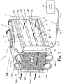
- FIG. 1 is a schematicized perspective view of heat exchanger system 10 of an environmental control system ("ECS") of an aircraft and shows heat exchanger 11, housing 12, flanges 14, inlets 16A and 16B, outlets 18A and 18B, ram inlet 20, ram outlet 22, core 24 (with fins 24A), closure bar 26, ram air circuit C RA , spray tube array 28 (with tubes 30, spray nozzles 32, and primary tube 34), supply line 36, connector 38, mounts 40, fluid source 42, source line 44, and connector 46.
- ECS environmental control system
- Heat exchanger 11 is a heat exchanger with a plurality of fins (i.e., fins 24A) for transferring thermal energy between the fins and a fluid (e.g., one or more sources of air).
- Housing 12 is an external casing of heat exchanger 11.
- Flanges 14 are flanges for attaching heat exchanger 11 to other components of the ECS and/or aircraft. In this example, flanges 14 are picture frame flanges.
- Inlets 16A and 16B and outlets 18A and 18B are fluidic openings.
- Ram inlet 20 is a fluidic entry point for a source of ram air circuit C RA from the aircraft.
- Ram outlet 22 is a fluidic exit point from heat exchanger 11 of ram air circuit C RA .
- Core 24 is a portion of heat exchanger 11 including heat exchanging fins 24 that are wavy sheets of solid material (e.g., metal) configured to transfer thermal energy between the heat exchanging fins and a fluid (e.g., ram air circuit C RA ) passing across the heat exchanging fins.
- Closure bar 26 is a flat piece of solid material.
- Ram air circuit C RA is a fluidic pathway or flow path.
- Spray tube array 28 is an assembly of tubes 30, spray nozzles 32, and primary tube 34.
- Tubes 30 and primary tube 34 are hollow tubes of solid material.
- tubes 30 include a circular cross-section shape (see e.g., FIG. 2 ).
- Spray nozzles 32 are orifices or openings.
- Supply line 36 and source line 44 are fluidic hoses or tubes for transporting a fluid.
- Connectors 38 and 46 are couplers or linking elements.
- connectors 38 and/or 40 can include threads for threadable engagement with each other.
- Mounts 40 are supports or struts.
- Fluid source 42 is a source of a pressurized fluid.
- fluid source 42 is a machine or device that provides a pressurized liquid for cleaning purposes, such as a portable pressure washer or similar apparatus.
- Heat exchanger 11 is disposed in and as a component of the ECS (not shown) of an aircraft.
- Housing 12 is connected to other components of the aircraft ECS via flanges 14.
- Flanges 14 are mounted to housing 12 via permanent or mechanical engagement.
- Inlet 16A is located in a top portion (top/upward as shown in FIG. 1 ) of heat exchanger 11 and is fluidly connected to a first portion of core 24.
- Inlet 16B is located in a bottom portion (bottom/downward as shown in FIG. 1 ) of heat exchanger 11 and is fluidly connected to a second portion of core 24.
- Outlet 18A is disposed on an upper portion of heat exchanger 11 and is fluidly connected to the first portion of core 24.
- Outlet 18B is disposed on a lower portion of heat exchanger 11 and is fluidly connected to the second portion of core 24.
- Ram inlet 20 and ram outlet 22 disposed on opposite sides of housing 12 form each other and are both fluidly connected to core 24.
- Core 24 is disposed and contained in housing 12.
- Closure bar 26 is disposed through a portion of heat exchanger 11.
- Ram air circuit C RA passes heat exchanger 11 via ram inlet 20, through core 24, and out of heat exchanger 11 via ram outlet 22.
- Spray tube array 28 is mounted to flanges 14 of housing 12 via mounts 40.
- tubes 30 are connected to and extend from primary tube 34. Each of tubes 30 is fluidly connected to supply line 36 via primary tube 34.
- tubes 30 are oriented in a horizontal arrangement relative to the positioning of heat exchanger 11.
- tubes 30 can include non-horizontal arrangements such as diagonal, vertical, as well as non-linear configurations such as circular or elliptical (see e.g., FIGS. 3A-3C ).
- Spray nozzles 32 are disposed along tubes 30. In this example, spray nozzles are shown in phantom to depict their locations on a backside of tubes 30 as shown in FIG.
- Primary tube 34 is connected to tubes 30 and to supply line 36.
- Supply line 36 connects to primary tube 34 and to source line 44 via connectors 38 and 46.
- Connector 38 is attached on an end of supply line 36 and is connected to connector 46.
- Mounts 40 are attached to and extend from flanges 14. In other embodiments, mounts 40 can attach to portions of heat exchanger 11 other than at flanges 14 such as to housing 12 and/or directly to core 24.
- Fluid source 42 is disposed externally from the ECS of the aircraft and is fluidly connected to spray tube array 28 via source line 44, connectors 46 and 38, and supply line 36.
- Source line 44 extends between and fluidly connects fluid source 42 and connector 46.
- Connector 46 is attached to source line 44 and is coupled to connector 38.
- Heat exchanger 11 transfers thermal energy (via hot layers and cold layers in core 24) between ram air circuit C RA and other air circuits passing through heat exchanger housing 12 in order to provide conditioned air to the ECS of the aircraft.
- Housing 12 houses core 24 and contains the air flow of ram air circuit C RA and other air circuits within heat exchanger 11.
- Flanges 14 provide interfaces with which additional ECS components attach to. In this example, flanges 14 provide an attachment point for mounts 40 to mount to.
- Inlets 16A and 16B deliver flow of air circuits (e.g., bleed air circuit and/or fresh air circuit) into housing 12 and to core 24.
- Outlets 18A and 18B deliver flow of air circuits (e.g., bleed air circuit and/or fresh air circuit) from core 24 and out of housing 12.
- Ram inlet 20 receives ram air circuit C RA into housing 12 and to core 24.
- Ram outlet 22 delivers ram air circuit C RA from core 24 and out of housing 12.
- Core 24 effectuates transfer of thermal energy between ram air circuit C RA and the other air circuits passing therethrough.
- Closure bar 26 fluidly separates a first top portion of core 24 from a second bottom portion of core 24.
- Ram air circuit C RA provides a source of cold air flow into which thermal energy is transferred from the other air circuits passing through core 24 of heat exchanger 11.
- Bars 30 of spray tube array 28 deliver a spray of cleaning fluid onto and into ram outlet 20 to wash and/or flush the cleaning fluid through the fins of core 24 in order to clean any accumulated debris or particulate from core 24.
- the term cleaning fluid can be pressurized hot water with a (environmentally safe) detergent additive.
- a heat exchanger cleaning process can involve multiple wash cycles (e.g., with the cleaning fluid) and rinse cycles (e.g., with plain water) until debris is no longer visible in heat exchanger 11 or in the waste liquid exiting heat exchanger 11.
- tubes 30 of spray tube array 28 cover as much of ram outlet 22 as practical in order to back-flush core 24 with water to remove any material clogging heat exchanger 11.
- Spray nozzles 32 create or impart a spout or spray of fluid from each of tubes 30.
- Primary tube 34 delivers the cleaning fluid from supply line 36 to tubes 30.
- Supply line 36 delivers the cleaning fluid from source line 44 to primary tube 34.
- Connector 38 engages with connector 46 so as to fluidly connected source line 44 to supply line 36.
- Mounts 40 attach or affix spray tube array 28 to housing 12 of heat exchanger 11.
- Fluid source 42 provides a pressurized source of cleaning fluid to spray tube array 28.
- Source line 44 delivers the cleaning fluid from fluid source 42 to supply line 36.
- a temporary pressurized fluid apparatus e.g., portable pressure washer
- a portable pressurized washer often results in a non-uniform spray of water and inconsistent spray coverage often leading to inefficient debris removal.
- Heat exchanger 11 with spray tube array 28 eliminates the need to access heat exchanger 11 during each cleaning process because spray tube array 28 is integral with heat exchanger 11 and therefore does not need to be introduced during each cleaning instance.
- Spray tube array 28 also eliminates the need to completely remove heat exchanger 11 from the aircraft in order to clean heat exchanger 11, which can be a difficult and time consuming process necessary with existing cleaning processes.
- connector 38 an easily accessible connection point is available with which fluid source 42 can be quickly connected during maintenance checks in order to provide pressurized water to spray tube array 28.
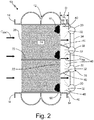
- FIG. 2 is a section view taken along plane 2-2 in FIG. 1 of heat exchanger 11.
- FIG. 2 shows fluid spraying from spray tube array 28 and includes heat exchanger 11, housing 12, flanges 14, ram inlet 20, ram outlet 22, core 24, closure bar 26, ram air circuit C RA , spray tube array 28 (with tubes 30, spray nozzles 32, and primary tube 34), and mounts 40.
- FIG. 2 also shows distance D between core 24 and tubes 30, sprays 48, and debris 50.
- Sprays 48 are spray patterns of a cleaning fluid such as water. In this example, patterns of sprays 48 include a conical or fan shape. Debris 50 are lumps of accumulated particulate or dirt.
- FIG. 2 shows additional mounts 40 attached to core 24 and to tubes 30.
- each of tubes 30 is set at a uniform distance D across the entire spray tube array 28. In other examples, one or more of tubes 30 can be set at a distance away from core 24 such that distance D is not uniform as between all of tubes 30 in spray tube array 28.
- Sprays 48 are sprayed out of or emitted from spray nozzles 32 of tubes 30. Debris 50 are disposed in portions (e.g., the fins) of core 24. In other examples other pieces of debris 50 can be located through any portion of core 24.
- the additional mounts 40 attached to core 24 and to tubes 30 provide addition support to spray tube array 28 and further maintain a consistent distance D across all of spray tube array 28.
- spray nozzles 32 are at a fixed distance from heat exchanger 11.
- Sprays 48 exit spray nozzles 32 and are sprayed through ram outlet 22 and into the fins of core 24 so as to flush out debris 50 from the fins with the cleaning fluid.
- debris 50 is removed from the fins of heat exchanger 11 with the cleaning fluid. Further, the cleaning fluid is then drained from the fins of core 24 by way of a drain in housing 12 or by flushing all the way out of core 24 through ram inlet 20.
- Sizes of existing heat exchanger fins can be as small as 3/1000's inch thick. If a high velocity spray is introduced onto such small of fins at an incorrect angle or at a distance too close to the fins, the fins can become bent or damaged.
- Spray tube array 28 that is mounted directly to housing 12 via mounts 40 allows for better control of the heat exchanger cleaning process by holding spray nozzles 32 of tubes 30 at a fixed distance from the fins of core 24 thereby eliminating the risk of bending the fins of core 24 over with sprays 48 or by contacting the fins with tubes 30.
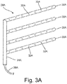
- FIG. 3A is a front view of spray tube array 28A and shows spray tubes 30A, spray nozzles 32A, primary tube 34A, and supply line 36A.
- FIG. 3A shows tubes 30A of spray tube array 28A as including a diagonal direction.
- tubes 30A are shown as including a downward slant in a right-to-left direction as shown in FIG. 3A .
- tubes 30A are shown as extending along a straight line.
- tubes 30A (or 30, 30B, and/or 30C) can include a horizontal, vertical, diagonal, circular, and/or wavy configuration.
- tubes 30A The diagonal configuration of tubes 30A enables any residual cleaning fluid to drain from tubes 30A upon completion of spraying heat exchanger 11. This natural drainage of tubes 30A helps to prevent pooling and subsequent freezing of the cleaning fluid inside of tubes 30A which can cause damage to spray tube array 28A.
- FIG. 3B is a front view of spray tube array 28B and shows spray tubes 30B, spray nozzles 32B, primary tube 34B, and supply line 36B.
- FIG. 3B shows tubes 30B of spray tube array 28B as including a vertical orientation. tubes 30B are connected to primary tube 34B which also includes spray nozzles 32B in this embodiment.
- This vertically orientated configuration of spray tube array 28B allows for the option of placing tubes 30B in a different pattern (than is shown in FIGS. 1-3A ) which may be more suitable to clean heat exchanger 11 depending on the use and characteristics of the aircraft heat exchanger 11 is installed in.
- primary tube 34B including spray nozzles 32B a larger amount of spray can be delivered to a gravitational bottom of core 24 where there could be a great amount of debris accumulation.
- FIG. 3C is a front view of spray tube array 28C and shows first spray tubes 30C, second set of spray tubes 30C', spray nozzles 32C, first primary tube 34C, second primary tube 34C', first supply line 36C, and second supply line 36C'.
- First and second tubes 30C and 30C' are shown as included a curved, bowed, or lenticular (e.g., biconvex) shapes.
- Second tubes 30C' also include arrowhead shaped portions extending diagonally downward from the curved portions. These portions extending diagonally downwards assist with delivering the cleaning fluid to the bottom corners of core 24 where debris 50 can accumulate at a high rate due to quiescence caused by fluid flow dynamics within heat exchanger 11.
- spray tube array 28C is shown as including more than one set of tubes that are each connected to their own respective fluid circuit. Utilizing more than one fluid circuit in spray tube array 28C allows for differing spray patterns, different pressures, and different time periods of spraying the cleaning fluid from each of first tubes 30C and second tubes 30C'. Varying the flow patterns and timing from each of first tubes 30C and second tubes 30C' enables different portions of core 24 to be cleaned at different rates. This allows for an adaptive cleaning process as well as more targeted cleaning treatments to portions of heat exchanger 11 tending to collect more debris 50. For example, in the corner regions of ram outlet 22, quiescent zones are present where the airflow through core 24 is not quite as high as through the center of core 24 due to the turbulence and fluid flow dynamics within of heat exchanger 11.
- a configuration such as provided by spray tube array 28C allows for addition flow of the cleaning fluid at portions of core 24 that are more susceptible to clogging.
- the multiple fluid circuit configuration of spray tube array 28C allows delivery of varying amounts of pressure of cleaning fluid as needed based on a specific need of heat exchanger 11.
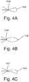
- FIG. 4A is a cross-sectional view of first spray tube 130A in a tear-drop shape and shows spray nozzle 132A.
- FIG. 4B is a cross-sectional view of second spray tube 130B in a lenticular shape and shows spray nozzle 132B.
- FIG. 4C is a cross-sectional view of third spray tube 130C in an airfoil shape and shows spray nozzle 132C.
- Each of the cross-section shapes of tubes 130A, 130B, and 130C presented in FIGS. 4A, 4B, and 4C provide aerodynamic shapes in order to minimize a pressure drop of ram air circuit C RA flowing across the tubes.
- Any of the cross section shapes as shown by first, second, and third tubes 130A, 130B, and 130C can be incorporated, alone or in combination) into any of the configurations of tubes shown throughout FIGS. 1 - 4C .
- third tubes 130C allow third tubed 130C to direct or guide (e.g., turn) a portion or portions of ram air circuit C RA in certain directions as ram air circuit C RA exits out of ram outlet 22 of heat exchanger 11.
- a heat exchanger cleaning arrangement includes a spray tube array configured to be attached to a heat exchanger.
- the spray tube array includes at least one tube, a plurality of nozzles, and a connector.
- the plurality of nozzles is configured to port pressurized fluid from the at least one tube toward the heat exchanger.
- the connector is in operable communication with the spray bar array and is configured such that a pressurized fluid source can be attached to the connector for porting fluid from the pressurized fluid source to the plurality of nozzles.
- the arrangement of the preceding paragraph can optionally include, additionally and/or alternatively, any one or more of the following features, configurations and/or additional components.
- Each tube of the array of spray tubes can be fluidly connected to a supply line.
- the housing can include a flange at the outlet, wherein the spray tube array can be mounted to the heat exchanger at a flange of a housing of the heat exchanger.
- a method of cleaning a heat exchanger includes connecting a pressurized fluid source to a spray bar array that is attached to a heat exchanger. Fluid is then flowed from the pressurized fluid source through at least one tube of the spray bar array and out of the at least one tube through a plurality of nozzles in the at least one tube toward a heat exchanger.
- the method of the preceding paragraph can optionally include, additionally and/or alternatively, any one or more of the following steps, features, configurations and/or additional components.
- a portion of the series of fins can be flushed with the fluid.
- Debris can be removed from the series of fins of the heat exchanger with the fluid.
- the fluid can be drained from the series of fins of the heat exchanger.
- a heat exchanger system includes a heat exchanger, a spray tube, and a supply line.
- the Heat exchanger includes a housing, a series of fins disposed within the housing, a first ram inlet disposed in the heat exchanger housing, and a first ram outlet disposed in the heat exchanger housing opposite from the first ram inlet.
- the spray tube is disposed at the first ram outlet of the heat exchanger and is affixed to a portion of the housing and comprises a plurality of nozzles aligned towards the heat exchanger.
- the supply line is fluidly connected to the spray tube and includes a fluid conduit and a connector disposed on an end of the supply line.
- the system of the preceding paragraph can optionally include, additionally and/or alternatively, any one or more of the following features, configurations and/or additional components.
- Each spray tube of an array of spray tubes can be fluidly connected to the supply line.
- the housing can include a flange at the outlet, wherein the spray tube can be mounted to the housing at the flange.
- the heat exchanger can be a ram air heat exchanger that can be configured to connect to an environmental control system of an aircraft.
Landscapes
- Engineering & Computer Science (AREA)
- Chemical & Material Sciences (AREA)
- Combustion & Propulsion (AREA)
- Mechanical Engineering (AREA)
- General Engineering & Computer Science (AREA)
- Heat-Exchange Devices With Radiators And Conduit Assemblies (AREA)
Abstract
Description
- The present disclosure relates to heat exchangers. More particularly, the present disclosure relates to the cleaning of heat exchangers.
- An environmental control system ("ECS") aboard an aircraft provides conditioned air to the aircraft cabin. Conditioned air is air at a desired temperature, pressure, and humidity for aircraft passenger comfort. Compressing ambient air at flight altitude heats the resulting pressurized air sufficiently that it must be cooled, even if the ambient air temperature is very low. Thus, under most conditions, heat must be removed from air by the ECS before the air is delivered to the aircraft cabin. As heat is removed from the air, it is dissipated by the ECS into a separate stream of air that flows into the ECS, across heat exchangers in the ECS, and out of the aircraft, carrying the excess heat with it.
- Clogging of the ECS heat exchanger is a common problem and as a result, customers often remove the heat exchanger at regular intervals for cleaning due to the performance degradation of the dirty clogged heat exchanger. The removal of the heat exchanger from the aircraft is time consuming and can potentially damage the heat exchanger or other equipment.
- A heat exchanger cleaning arrangement includes a spray tube array configured to be attached to a heat exchanger. The spray tube array includes at least one tube, a plurality of nozzles, and a connector. The plurality of nozzles is configured to port pressurized fluid from the at least one tube toward the heat exchanger. The connector is in operable communication with the spray bar array and is configured such that a pressurized fluid source can be attached to the connector for porting fluid from the pressurized fluid source to the plurality of nozzles.
- A method of cleaning a heat exchanger includes connecting a pressurized fluid source to a spray bar array that is attached to a heat exchanger. Fluid is then flowed from the pressurized fluid source through at least one tube of the spray bar array and out of the at least one tube through a plurality of nozzles in the at least one tube toward a heat exchanger.
- A heat exchanger system includes a heat exchanger, a spray tube, and a supply line. The Heat exchanger includes a housing, a series of fins disposed within the housing, a first ram inlet disposed in the heat exchanger housing, and a first ram outlet disposed in the heat exchanger housing opposite from the first ram inlet. The spray tube is disposed at the first ram outlet of the heat exchanger and is affixed to a portion of the housing and comprises a plurality of nozzles aligned towards the heat exchanger. The supply line is fluidly connected to the spray tube and includes a fluid conduit and a connector disposed on an end of the supply line.
- The present summary is provided only by way of example, and not limitation. Other aspects of the present disclosure will be appreciated in view of the entirety of the present disclosure, including the entire text, claims, and accompanying figures.
-
-
FIG. 1 is a schematicized perspective view of a heat exchanger of an environmental control system of an aircraft and shows a spray tube array mounted onto a flange of the heat exchanger. -
FIG. 2 is a section view taken along plane 2-2 inFIG. 1 of the heat exchanger and shows fluid spraying from the spray tube array. -
FIG. 3A is a front view of a first spray tube array with diagonal spray tubes. -
FIG. 3B is a front view of a second spray tube array with vertical spray tubes. -
FIG. 3C is a front view of a third spray tube array with two separate spray tube circuits. -
FIG. 4A is a cross-sectional view of first spray tube in a tear-drop shape. -
FIG. 4B is a cross-sectional view of second spray tube in a lenticular shape. -
FIG. 4C is a cross-sectional view of third spray tube in an airfoil shape. - While the above-identified figures set forth one or more embodiments of the present disclosure, other embodiments are also contemplated, as noted in the discussion. In all cases, this disclosure presents the invention by way of representation and not limitation. It should be understood that numerous other modifications and embodiments can be devised by those skilled in the art, which fall within the scope of the invention as defined by the claims. The figures may not be drawn to scale, and applications and embodiments of the present invention may include features and components not specifically shown in the drawings.
- In the present disclosure, a spray tube array is mounted near the downstream face of the heat exchanger with an easily accessible connection to attach a high pressure water source in order to provide a consistent and repeatable cleaning process. The spray tube array covers as much of the heat exchanger outlet face as practical in order to back-flush the heat exchanger with water to remove any material clogging the heat exchanger. Existing access panels in some heat exchanger housings allow cleaning, but there is no easy way to guarantee total coverage with the water spray. The configuration presented herein allows for a repeatable cleaning process of the heat exchanger core without needing to remove the heat exchanger from the aircraft.
-
FIG. 1 is a schematicized perspective view ofheat exchanger system 10 of an environmental control system ("ECS") of an aircraft and shows heat exchanger 11,housing 12,flanges 14,inlets outlets ram inlet 20,ram outlet 22, core 24 (with fins 24A),closure bar 26, ram air circuit CRA, spray tube array 28 (withtubes 30,spray nozzles 32, and primary tube 34),supply line 36,connector 38,mounts 40,fluid source 42,source line 44, andconnector 46. - Heat exchanger 11 is a heat exchanger with a plurality of fins (i.e.,
fins 24A) for transferring thermal energy between the fins and a fluid (e.g., one or more sources of air).Housing 12 is an external casing of heat exchanger 11.Flanges 14 are flanges for attaching heat exchanger 11 to other components of the ECS and/or aircraft. In this example,flanges 14 are picture frame flanges.Inlets outlets inlet 20 is a fluidic entry point for a source of ram air circuit CRA from the aircraft. Ramoutlet 22 is a fluidic exit point from heat exchanger 11 of ram air circuit CRA. Core 24 is a portion of heat exchanger 11 including heat exchanging fins 24 that are wavy sheets of solid material (e.g., metal) configured to transfer thermal energy between the heat exchanging fins and a fluid (e.g., ram air circuit CRA) passing across the heat exchanging fins. Closurebar 26 is a flat piece of solid material. Ram air circuit CRA is a fluidic pathway or flow path. -
Spray tube array 28 is an assembly oftubes 30,spray nozzles 32, andprimary tube 34.Tubes 30 andprimary tube 34 are hollow tubes of solid material. In this example,tubes 30 include a circular cross-section shape (see e.g.,FIG. 2 ).Spray nozzles 32 are orifices or openings.Supply line 36 andsource line 44 are fluidic hoses or tubes for transporting a fluid.Connectors connectors 38 and/or 40 can include threads for threadable engagement with each other.Mounts 40 are supports or struts.Fluid source 42 is a source of a pressurized fluid. In this example,fluid source 42 is a machine or device that provides a pressurized liquid for cleaning purposes, such as a portable pressure washer or similar apparatus. - Heat exchanger 11 is disposed in and as a component of the ECS (not shown) of an aircraft.
Housing 12 is connected to other components of the aircraft ECS viaflanges 14.Flanges 14 are mounted tohousing 12 via permanent or mechanical engagement.Inlet 16A is located in a top portion (top/upward as shown inFIG. 1 ) of heat exchanger 11 and is fluidly connected to a first portion ofcore 24.Inlet 16B is located in a bottom portion (bottom/downward as shown inFIG. 1 ) of heat exchanger 11 and is fluidly connected to a second portion ofcore 24.Outlet 18A is disposed on an upper portion of heat exchanger 11 and is fluidly connected to the first portion ofcore 24.Outlet 18B is disposed on a lower portion of heat exchanger 11 and is fluidly connected to the second portion ofcore 24.Ram inlet 20 andram outlet 22 disposed on opposite sides ofhousing 12 form each other and are both fluidly connected tocore 24.Core 24 is disposed and contained inhousing 12.Closure bar 26 is disposed through a portion of heat exchanger 11. Ram air circuit CRA passes heat exchanger 11 viaram inlet 20, throughcore 24, and out of heat exchanger 11 viaram outlet 22. - Spray
tube array 28 is mounted toflanges 14 ofhousing 12 via mounts 40.tubes 30 are connected to and extend fromprimary tube 34. Each oftubes 30 is fluidly connected to supplyline 36 viaprimary tube 34. In this example,tubes 30 are oriented in a horizontal arrangement relative to the positioning of heat exchanger 11. In other examples,tubes 30 can include non-horizontal arrangements such as diagonal, vertical, as well as non-linear configurations such as circular or elliptical (see e.g.,FIGS. 3A-3C ). Spraynozzles 32 are disposed alongtubes 30. In this example, spray nozzles are shown in phantom to depict their locations on a backside oftubes 30 as shown inFIG. 1 (e.g., on a side oftubes 30 facing towardscore 24 of heat exchanger 11).Primary tube 34 is connected totubes 30 and to supplyline 36.Supply line 36 connects toprimary tube 34 and to sourceline 44 viaconnectors Connector 38 is attached on an end ofsupply line 36 and is connected toconnector 46.Mounts 40 are attached to and extend fromflanges 14. In other embodiments, mounts 40 can attach to portions of heat exchanger 11 other than atflanges 14 such as tohousing 12 and/or directly tocore 24. -
Fluid source 42 is disposed externally from the ECS of the aircraft and is fluidly connected to spraytube array 28 viasource line 44,connectors supply line 36.Source line 44 extends between and fluidly connectsfluid source 42 andconnector 46.Connector 46 is attached to sourceline 44 and is coupled toconnector 38. - Heat exchanger 11 transfers thermal energy (via hot layers and cold layers in core 24) between ram air circuit CRA and other air circuits passing through
heat exchanger housing 12 in order to provide conditioned air to the ECS of the aircraft.Housing 12houses core 24 and contains the air flow of ram air circuit CRA and other air circuits within heat exchanger 11.Flanges 14 provide interfaces with which additional ECS components attach to. In this example,flanges 14 provide an attachment point formounts 40 to mount to.Inlets housing 12 and tocore 24.Outlets core 24 and out ofhousing 12.Ram inlet 20 receives ram air circuit CRA intohousing 12 and tocore 24.Ram outlet 22 delivers ram air circuit CRA fromcore 24 and out ofhousing 12.Core 24 effectuates transfer of thermal energy between ram air circuit CRA and the other air circuits passing therethrough.Closure bar 26 fluidly separates a first top portion ofcore 24 from a second bottom portion ofcore 24. Ram air circuit CRA provides a source of cold air flow into which thermal energy is transferred from the other air circuits passing throughcore 24 of heat exchanger 11. - For additional discussion of an exemplary heat exchanger, see commonly owned United States Patent Application Serial No.
16/213,217 -
Bars 30 ofspray tube array 28 deliver a spray of cleaning fluid onto and intoram outlet 20 to wash and/or flush the cleaning fluid through the fins ofcore 24 in order to clean any accumulated debris or particulate fromcore 24. In this non-limiting embodiment, the term cleaning fluid can be pressurized hot water with a (environmentally safe) detergent additive. For example, a heat exchanger cleaning process can involve multiple wash cycles (e.g., with the cleaning fluid) and rinse cycles (e.g., with plain water) until debris is no longer visible in heat exchanger 11 or in the waste liquid exiting heat exchanger 11. - In one example,
tubes 30 ofspray tube array 28 cover as much ofram outlet 22 as practical in order to back-flush core 24 with water to remove any material clogging heat exchanger 11. Spraynozzles 32 create or impart a spout or spray of fluid from each oftubes 30.Primary tube 34 delivers the cleaning fluid fromsupply line 36 totubes 30.Supply line 36 delivers the cleaning fluid fromsource line 44 toprimary tube 34.Connector 38 engages withconnector 46 so as to fluidlyconnected source line 44 to supplyline 36.Mounts 40 attach or affixspray tube array 28 tohousing 12 of heat exchanger 11.Fluid source 42 provides a pressurized source of cleaning fluid to spraytube array 28.Source line 44 delivers the cleaning fluid fromfluid source 42 to supplyline 36. - With existing cleaning systems for heat exchangers, mechanics are required to access the heat exchanger by removing a panel in the aircraft exterior. Once the heat exchanger outlet is exposed, a temporary pressurized fluid apparatus (e.g., portable pressure washer) is used to introduce a pressurized stream of water onto the heat exchanger outlet. Use of a portable pressurized washer often results in a non-uniform spray of water and inconsistent spray coverage often leading to inefficient debris removal. There is no easy way to guarantee total coverage with the water spray with existing methods. In addition, there is a risk of the spray nozzle of the pressure washer coming into contact with the fins of the heat exchanger causing damage.
- Heat exchanger 11 with
spray tube array 28 eliminates the need to access heat exchanger 11 during each cleaning process becausespray tube array 28 is integral with heat exchanger 11 and therefore does not need to be introduced during each cleaning instance. Spraytube array 28 also eliminates the need to completely remove heat exchanger 11 from the aircraft in order to clean heat exchanger 11, which can be a difficult and time consuming process necessary with existing cleaning processes. With the use ofconnector 38, an easily accessible connection point is available with whichfluid source 42 can be quickly connected during maintenance checks in order to provide pressurized water to spraytube array 28. -
FIG. 2 is a section view taken along plane 2-2 inFIG. 1 of heat exchanger 11.FIG. 2 shows fluid spraying fromspray tube array 28 and includes heat exchanger 11,housing 12,flanges 14,ram inlet 20,ram outlet 22,core 24,closure bar 26, ram air circuit CRA, spray tube array 28 (withtubes 30,spray nozzles 32, and primary tube 34), and mounts 40.FIG. 2 also shows distance D betweencore 24 andtubes 30,sprays 48, anddebris 50. - Distance D is a length between
core 24 andtubes 30.Sprays 48 are spray patterns of a cleaning fluid such as water. In this example, patterns ofsprays 48 include a conical or fan shape.Debris 50 are lumps of accumulated particulate or dirt. Here,FIG. 2 showsadditional mounts 40 attached tocore 24 and totubes 30. In this example, each oftubes 30 is set at a uniform distance D across the entirespray tube array 28. In other examples, one or more oftubes 30 can be set at a distance away fromcore 24 such that distance D is not uniform as between all oftubes 30 inspray tube array 28.Sprays 48 are sprayed out of or emitted fromspray nozzles 32 oftubes 30.Debris 50 are disposed in portions (e.g., the fins) ofcore 24. In other examples other pieces ofdebris 50 can be located through any portion ofcore 24. - The additional mounts 40 attached to
core 24 and totubes 30 provide addition support to spraytube array 28 and further maintain a consistent distance D across all ofspray tube array 28. Withmounts 40 holding tubes 30 a set distance D fromcore 24,spray nozzles 32 are at a fixed distance from heat exchanger 11.Sprays 48exit spray nozzles 32 and are sprayed throughram outlet 22 and into the fins ofcore 24 so as to flush outdebris 50 from the fins with the cleaning fluid. Assprays 48 come into contact with the fins ofcore 24,debris 50 is removed from the fins of heat exchanger 11 with the cleaning fluid. Further, the cleaning fluid is then drained from the fins ofcore 24 by way of a drain inhousing 12 or by flushing all the way out ofcore 24 throughram inlet 20. - Sizes of existing heat exchanger fins can be as small as 3/1000's inch thick. If a high velocity spray is introduced onto such small of fins at an incorrect angle or at a distance too close to the fins, the fins can become bent or damaged. Spray
tube array 28 that is mounted directly tohousing 12 viamounts 40 allows for better control of the heat exchanger cleaning process by holdingspray nozzles 32 oftubes 30 at a fixed distance from the fins ofcore 24 thereby eliminating the risk of bending the fins ofcore 24 over withsprays 48 or by contacting the fins withtubes 30. -
FIG. 3A is a front view ofspray tube array 28A and showsspray tubes 30A,spray nozzles 32A,primary tube 34A, andsupply line 36A. Here,FIG. 3A showstubes 30A ofspray tube array 28A as including a diagonal direction. For example,tubes 30A are shown as including a downward slant in a right-to-left direction as shown inFIG. 3A . In this embodiment,tubes 30A are shown as extending along a straight line. In other embodiments,tubes 30A (or 30, 30B, and/or 30C) can include a horizontal, vertical, diagonal, circular, and/or wavy configuration. - The diagonal configuration of
tubes 30A enables any residual cleaning fluid to drain fromtubes 30A upon completion of spraying heat exchanger 11. This natural drainage oftubes 30A helps to prevent pooling and subsequent freezing of the cleaning fluid inside oftubes 30A which can cause damage to spraytube array 28A. -
FIG. 3B is a front view ofspray tube array 28B and showsspray tubes 30B,spray nozzles 32B,primary tube 34B, andsupply line 36B. Here,FIG. 3B showstubes 30B ofspray tube array 28B as including a vertical orientation.tubes 30B are connected toprimary tube 34B which also includesspray nozzles 32B in this embodiment. - This vertically orientated configuration of
spray tube array 28B allows for the option of placingtubes 30B in a different pattern (than is shown inFIGS. 1-3A ) which may be more suitable to clean heat exchanger 11 depending on the use and characteristics of the aircraft heat exchanger 11 is installed in. For example, withprimary tube 34B includingspray nozzles 32B, a larger amount of spray can be delivered to a gravitational bottom ofcore 24 where there could be a great amount of debris accumulation. -
FIG. 3C is a front view ofspray tube array 28C and showsfirst spray tubes 30C, second set ofspray tubes 30C',spray nozzles 32C, firstprimary tube 34C, secondprimary tube 34C',first supply line 36C, andsecond supply line 36C'. First andsecond tubes Second tubes 30C' also include arrowhead shaped portions extending diagonally downward from the curved portions. These portions extending diagonally downwards assist with delivering the cleaning fluid to the bottom corners ofcore 24 wheredebris 50 can accumulate at a high rate due to quiescence caused by fluid flow dynamics within heat exchanger 11. - Here,
spray tube array 28C is shown as including more than one set of tubes that are each connected to their own respective fluid circuit. Utilizing more than one fluid circuit inspray tube array 28C allows for differing spray patterns, different pressures, and different time periods of spraying the cleaning fluid from each offirst tubes 30C andsecond tubes 30C'. Varying the flow patterns and timing from each offirst tubes 30C andsecond tubes 30C' enables different portions ofcore 24 to be cleaned at different rates. This allows for an adaptive cleaning process as well as more targeted cleaning treatments to portions of heat exchanger 11 tending to collectmore debris 50. For example, in the corner regions ofram outlet 22, quiescent zones are present where the airflow throughcore 24 is not quite as high as through the center ofcore 24 due to the turbulence and fluid flow dynamics within of heat exchanger 11. A configuration such as provided byspray tube array 28C allows for addition flow of the cleaning fluid at portions ofcore 24 that are more susceptible to clogging. The multiple fluid circuit configuration ofspray tube array 28C allows delivery of varying amounts of pressure of cleaning fluid as needed based on a specific need of heat exchanger 11. -
FIG. 4A is a cross-sectional view offirst spray tube 130A in a tear-drop shape and showsspray nozzle 132A.FIG. 4B is a cross-sectional view ofsecond spray tube 130B in a lenticular shape and showsspray nozzle 132B.FIG. 4C is a cross-sectional view ofthird spray tube 130C in an airfoil shape and showsspray nozzle 132C. Each of the cross-section shapes oftubes FIGS. 4A, 4B, and 4C provide aerodynamic shapes in order to minimize a pressure drop of ram air circuit CRA flowing across the tubes. Any of the cross section shapes as shown by first, second, andthird tubes FIGS. 1 - 4C . - Additionally, the airfoil shape of
third tubes 130C allow third tubed 130C to direct or guide (e.g., turn) a portion or portions of ram air circuit CRA in certain directions as ram air circuit CRA exits out ofram outlet 22 of heat exchanger 11. - A heat exchanger cleaning arrangement includes a spray tube array configured to be attached to a heat exchanger. The spray tube array includes at least one tube, a plurality of nozzles, and a connector. The plurality of nozzles is configured to port pressurized fluid from the at least one tube toward the heat exchanger. The connector is in operable communication with the spray bar array and is configured such that a pressurized fluid source can be attached to the connector for porting fluid from the pressurized fluid source to the plurality of nozzles.
- The arrangement of the preceding paragraph can optionally include, additionally and/or alternatively, any one or more of the following features, configurations and/or additional components.
- Each tube of the array of spray tubes can be fluidly connected to a supply line.
- The housing can include a flange at the outlet, wherein the spray tube array can be mounted to the heat exchanger at a flange of a housing of the heat exchanger.
- A method of cleaning a heat exchanger includes connecting a pressurized fluid source to a spray bar array that is attached to a heat exchanger. Fluid is then flowed from the pressurized fluid source through at least one tube of the spray bar array and out of the at least one tube through a plurality of nozzles in the at least one tube toward a heat exchanger.
- The method of the preceding paragraph can optionally include, additionally and/or alternatively, any one or more of the following steps, features, configurations and/or additional components.
- A portion of the series of fins can be flushed with the fluid.
- Debris can be removed from the series of fins of the heat exchanger with the fluid.
- The fluid can be drained from the series of fins of the heat exchanger.
- A heat exchanger system includes a heat exchanger, a spray tube, and a supply line. The Heat exchanger includes a housing, a series of fins disposed within the housing, a first ram inlet disposed in the heat exchanger housing, and a first ram outlet disposed in the heat exchanger housing opposite from the first ram inlet. The spray tube is disposed at the first ram outlet of the heat exchanger and is affixed to a portion of the housing and comprises a plurality of nozzles aligned towards the heat exchanger. The supply line is fluidly connected to the spray tube and includes a fluid conduit and a connector disposed on an end of the supply line.
- The system of the preceding paragraph can optionally include, additionally and/or alternatively, any one or more of the following features, configurations and/or additional components.
- Each spray tube of an array of spray tubes can be fluidly connected to the supply line.
- The housing can include a flange at the outlet, wherein the spray tube can be mounted to the housing at the flange.
- The heat exchanger can be a ram air heat exchanger that can be configured to connect to an environmental control system of an aircraft.
- While the invention has been described with reference to an exemplary embodiment(s), it will be understood by those skilled in the art that various changes may be made and equivalents may be substituted for elements thereof without departing from the scope of the invention. In addition, many modifications may be made to adapt a particular situation or material to the teachings of the invention without departing from the scope thereof. Therefore, it is intended that the invention not be limited to the particular embodiment(s) disclosed, but that the invention will include all embodiments falling within the scope of the appended claims.
Claims (10)
- A heat exchanger cleaning arrangement comprising:
a spray tube array (28) configured to be attached to a heat exchanger (11) having;at least one tube (30);a plurality of nozzles (32) configured to port pressurized fluid from the at least one tube toward the heat exchanger;a connector (38) in operable communication with the spray bar array and configured such that a pressurized fluid source can be attached to the connector for porting fluid from the pressurized fluid source to the plurality of nozzles. - The heat exchanger system of claim 1, further comprising a supply line (36), wherein each tube of the array of spray tubes is fluidly connected to the supply line.
- The heat exchanger system of claim 1 or 2, wherein the housing includes a flange (14) at the outlet (18A), wherein the spray tube array is mounted to the heat exchanger at a flange of a housing of the heat exchanger.
- A method of cleaning a heat exchanger comprising:connecting a pressurized fluid source to a spray bar array that is attached to a heat exchanger; andflowing fluid from the pressurized fluid source through at least one tube of the spray bar array and out of the at least one tube through a plurality of nozzles in the at least one tube toward a heat exchanger.
- The method of claim 4, further comprising flushing a portion of the series of fins with the fluid.
- The method of claim 5, further comprising removing debris from the series of fins of the heat exchanger with the fluid.
- The method of claim 6, further comprising draining the fluid from the series of fins of the heat exchanger.
- A heat exchanger system comprising:a heat exchanger (11) comprising:a housing (12);a series of fins (24A) disposed within the housing;a first ram inlet (16A) disposed in the heat exchanger housing; anda first ram outlet (18A) disposed in the heat exchanger housing opposite from the first ram inlet; anda heat exchanger cleaning arrangement as claimed in any of claims 1 to 3, wherein:the at least one tube (30) is disposed at the first ram outlet of the heat exchanger, wherein the spray tube is affixed to a portion of the housing and comprises the plurality of nozzles aligned towards the heat exchanger; and further comprisinga supply line fluidly connected to the spray tube, wherein the supply line comprises a fluid conduit and the connector disposed on an end of the supply line.
- The heat exchanger system of claim 8, wherein the spray tube array comprises a plurality of spray tubes, wherein each spray tube of the array of spray tubes is fluidly connected to the supply line.
- The heat exchanger system of claim 8 or 9, wherein the heat exchanger is a ram air heat exchanger that is configured to connect to an environmental control system of an aircraft.
Applications Claiming Priority (1)
| Application Number | Priority Date | Filing Date | Title |
|---|---|---|---|
| US16/293,025 US11105569B2 (en) | 2019-03-05 | 2019-03-05 | Heat exchanger spray tube |
Publications (2)
| Publication Number | Publication Date |
|---|---|
| EP3705833A1 true EP3705833A1 (en) | 2020-09-09 |
| EP3705833B1 EP3705833B1 (en) | 2022-01-19 |
Family
ID=68653359
Family Applications (1)
| Application Number | Title | Priority Date | Filing Date |
|---|---|---|---|
| EP19210662.3A Active EP3705833B1 (en) | 2019-03-05 | 2019-11-21 | Heat exchanger spray tube |
Country Status (2)
| Country | Link |
|---|---|
| US (1) | US11105569B2 (en) |
| EP (1) | EP3705833B1 (en) |
Cited By (1)
| Publication number | Priority date | Publication date | Assignee | Title |
|---|---|---|---|---|
| US20240068750A1 (en) * | 2022-08-24 | 2024-02-29 | Blue Box Air, Llc | Closed loop, modular and self-cleaning hvac system |
Families Citing this family (7)
| Publication number | Priority date | Publication date | Assignee | Title |
|---|---|---|---|---|
| US11371788B2 (en) * | 2018-09-10 | 2022-06-28 | General Electric Company | Heat exchangers with a particulate flushing manifold and systems and methods of flushing particulates from a heat exchanger |
| US11408694B2 (en) * | 2020-03-19 | 2022-08-09 | Saudi Arabian Oil Company | Reciprocating spray cleaning system for air-cooled heat exchangers |
| CN113137868B (en) * | 2021-05-28 | 2023-08-29 | 瀚能(苏州)节能科技有限公司 | A heat exchanger with spray cleaning function |
| US12516895B2 (en) | 2022-02-16 | 2026-01-06 | Blue Box Air, Llc | Apparatus and methods for self-cleaning and maintaining HVAC heat transfer coils |
| US20230280116A1 (en) * | 2022-03-04 | 2023-09-07 | Blue Box Air, Llc | Deep draw hvac coils with built-in self-cleaning mechanism and method of treating deep hvac coils |
| US12296293B2 (en) | 2022-09-27 | 2025-05-13 | Blue Box Air, Llc | Method and system for automated cleaning of filter wall for HVAC systems |
| US12253025B1 (en) * | 2024-02-27 | 2025-03-18 | General Electric Company | De-ice system and apparatus for turbine engines |
Citations (4)
| Publication number | Priority date | Publication date | Assignee | Title |
|---|---|---|---|---|
| WO1993018362A1 (en) * | 1992-03-09 | 1993-09-16 | The King Company | Coil cleansing assembly |
| EP2034266A2 (en) * | 2007-09-10 | 2009-03-11 | J&W Reinigungssysteme GmbH | Heat exchange device with angled or perpendicular surfaces and with cleaning |
| FR2955651A1 (en) * | 2010-01-25 | 2011-07-29 | A X Services | Device for cleaning mobile surfaces e.g. cooling tubes, of heat exchanger, has motorization units cooperating with flexible pipe to push or to withdraw flexible pipe from guiding section for displacing carriage along guiding section |
| WO2017028959A1 (en) * | 2015-08-14 | 2017-02-23 | Khadjavi Armin Fazlollah | Cleaning device for a heat exchanger |
Family Cites Families (14)
| Publication number | Priority date | Publication date | Assignee | Title |
|---|---|---|---|---|
| GB278854A (en) * | 1926-09-04 | 1927-10-20 | Whittemore Hulbert Whittemore | Improvements in boiler cleaners |
| US2121493A (en) * | 1934-11-07 | 1938-06-21 | Diamond Power Speciality | Boiler cleaner |
| US4562885A (en) * | 1983-08-29 | 1986-01-07 | General Resource Corporation | Plate heat exchanger and pressure blast cleaner |
| US4666531A (en) | 1984-12-18 | 1987-05-19 | Minard Gary A | Device and method for cleaning fin-type heat exchangers in air ducts |
| US20090230217A1 (en) * | 2008-03-14 | 2009-09-17 | Stone Ronald K | Insulated cleaning tool |
| ES2617216T3 (en) * | 2011-03-29 | 2017-06-15 | Lg Electronics Inc. | Clothing treatment apparatus incorporating a cleaning device with heat exchanger |
| US9568260B2 (en) * | 2011-05-02 | 2017-02-14 | Horton, Inc. | Heat exchanger blower method |
| US9784510B2 (en) * | 2011-12-28 | 2017-10-10 | Saudi Arabian Oil Company | Cleaning apparatus for heat exchange tubes of air cooled heat exchangers |
| SE538286C2 (en) * | 2012-09-11 | 2016-04-26 | Adaptum Ab | System for cleaning heat exchangers and method for cleaning heat exchangers |
| CN203274590U (en) | 2013-05-21 | 2013-11-06 | 侯立国 | Airborne heat exchanger self-cleaning system |
| JP5964286B2 (en) * | 2013-12-27 | 2016-08-03 | 三菱日立パワーシステムズ株式会社 | Heat exchanger |
| US10907914B2 (en) * | 2018-05-09 | 2021-02-02 | Saudi Arabian Oil Company | Air-cooled heat exchanger cleaning and temperature control apparatus and method |
| US11260977B2 (en) * | 2018-12-04 | 2022-03-01 | The Boeing Company | Filtration apparatus for use with aircraft |
| US11040777B2 (en) * | 2018-12-04 | 2021-06-22 | The Boeing Company | Cleanout systems for use with aircraft |
-
2019
- 2019-03-05 US US16/293,025 patent/US11105569B2/en active Active
- 2019-11-21 EP EP19210662.3A patent/EP3705833B1/en active Active
Patent Citations (4)
| Publication number | Priority date | Publication date | Assignee | Title |
|---|---|---|---|---|
| WO1993018362A1 (en) * | 1992-03-09 | 1993-09-16 | The King Company | Coil cleansing assembly |
| EP2034266A2 (en) * | 2007-09-10 | 2009-03-11 | J&W Reinigungssysteme GmbH | Heat exchange device with angled or perpendicular surfaces and with cleaning |
| FR2955651A1 (en) * | 2010-01-25 | 2011-07-29 | A X Services | Device for cleaning mobile surfaces e.g. cooling tubes, of heat exchanger, has motorization units cooperating with flexible pipe to push or to withdraw flexible pipe from guiding section for displacing carriage along guiding section |
| WO2017028959A1 (en) * | 2015-08-14 | 2017-02-23 | Khadjavi Armin Fazlollah | Cleaning device for a heat exchanger |
Cited By (1)
| Publication number | Priority date | Publication date | Assignee | Title |
|---|---|---|---|---|
| US20240068750A1 (en) * | 2022-08-24 | 2024-02-29 | Blue Box Air, Llc | Closed loop, modular and self-cleaning hvac system |
Also Published As
| Publication number | Publication date |
|---|---|
| EP3705833B1 (en) | 2022-01-19 |
| US20200284534A1 (en) | 2020-09-10 |
| US11105569B2 (en) | 2021-08-31 |
Similar Documents
| Publication | Publication Date | Title |
|---|---|---|
| EP3705833B1 (en) | Heat exchanger spray tube | |
| EP2536935B1 (en) | Coil arrangements for air intake system for gas turbine and methods | |
| EP3663204B1 (en) | Dual pass heat exchanger with drain system | |
| US11371788B2 (en) | Heat exchangers with a particulate flushing manifold and systems and methods of flushing particulates from a heat exchanger | |
| US4666531A (en) | Device and method for cleaning fin-type heat exchangers in air ducts | |
| US11040777B2 (en) | Cleanout systems for use with aircraft | |
| US11260977B2 (en) | Filtration apparatus for use with aircraft | |
| JP5842876B2 (en) | Dust collector for painting system | |
| JPH06129794A (en) | Crossflow type cooler, filter tank and pressure reducing mechanism | |
| US3963464A (en) | Gas washer and liquid treatment system | |
| CN102645936A (en) | Flow path structure and electronic apparatus | |
| US4394142A (en) | Water spray cooler | |
| US10689121B2 (en) | Heat exchanger with external plenum | |
| CN112013692B (en) | Cooling tower | |
| JP6707347B2 (en) | Water injection device for aircraft cooling system | |
| JP4588910B2 (en) | Water-soluble paint booth with exhaust circuit | |
| CN216049274U (en) | Prevent wet-type air cooler of jam | |
| CN117346249A (en) | Air conditioner terminal equipment, air conditioner and control method of air conditioner | |
| JP2013154319A (en) | Spraying device | |
| CN212327545U (en) | Cooling device | |
| JP2003260388A (en) | painting booth | |
| PL73394Y1 (en) | Device for cleaning radiators | |
| US10619937B2 (en) | Environmental control system tri-heat exchanger | |
| CN116518495A (en) | Radiating tube easy to disassemble and connect | |
| CN113819644A (en) | Air conditioner with split drainage structure |
Legal Events
| Date | Code | Title | Description |
|---|---|---|---|
| PUAI | Public reference made under article 153(3) epc to a published international application that has entered the european phase |
Free format text: ORIGINAL CODE: 0009012 |
|
| STAA | Information on the status of an ep patent application or granted ep patent |
Free format text: STATUS: THE APPLICATION HAS BEEN PUBLISHED |
|
| AK | Designated contracting states |
Kind code of ref document: A1 Designated state(s): AL AT BE BG CH CY CZ DE DK EE ES FI FR GB GR HR HU IE IS IT LI LT LU LV MC MK MT NL NO PL PT RO RS SE SI SK SM TR |
|
| AX | Request for extension of the european patent |
Extension state: BA ME |
|
| STAA | Information on the status of an ep patent application or granted ep patent |
Free format text: STATUS: REQUEST FOR EXAMINATION WAS MADE |
|
| 17P | Request for examination filed |
Effective date: 20210309 |
|
| RBV | Designated contracting states (corrected) |
Designated state(s): AL AT BE BG CH CY CZ DE DK EE ES FI FR GB GR HR HU IE IS IT LI LT LU LV MC MK MT NL NO PL PT RO RS SE SI SK SM TR |
|
| GRAP | Despatch of communication of intention to grant a patent |
Free format text: ORIGINAL CODE: EPIDOSNIGR1 |
|
| STAA | Information on the status of an ep patent application or granted ep patent |
Free format text: STATUS: GRANT OF PATENT IS INTENDED |
|
| RIC1 | Information provided on ipc code assigned before grant |
Ipc: F28G 1/16 20060101AFI20210907BHEP |
|
| INTG | Intention to grant announced |
Effective date: 20211001 |
|
| GRAS | Grant fee paid |
Free format text: ORIGINAL CODE: EPIDOSNIGR3 |
|
| GRAA | (expected) grant |
Free format text: ORIGINAL CODE: 0009210 |
|
| STAA | Information on the status of an ep patent application or granted ep patent |
Free format text: STATUS: THE PATENT HAS BEEN GRANTED |
|
| AK | Designated contracting states |
Kind code of ref document: B1 Designated state(s): AL AT BE BG CH CY CZ DE DK EE ES FI FR GB GR HR HU IE IS IT LI LT LU LV MC MK MT NL NO PL PT RO RS SE SI SK SM TR |
|
| REG | Reference to a national code |
Ref country code: GB Ref legal event code: FG4D |
|
| REG | Reference to a national code |
Ref country code: CH Ref legal event code: EP |
|
| REG | Reference to a national code |
Ref country code: DE Ref legal event code: R096 Ref document number: 602019011024 Country of ref document: DE |
|
| REG | Reference to a national code |
Ref country code: AT Ref legal event code: REF Ref document number: 1464043 Country of ref document: AT Kind code of ref document: T Effective date: 20220215 |
|
| REG | Reference to a national code |
Ref country code: IE Ref legal event code: FG4D |
|
| REG | Reference to a national code |
Ref country code: LT Ref legal event code: MG9D |
|
| REG | Reference to a national code |
Ref country code: NL Ref legal event code: MP Effective date: 20220119 |
|
| REG | Reference to a national code |
Ref country code: AT Ref legal event code: MK05 Ref document number: 1464043 Country of ref document: AT Kind code of ref document: T Effective date: 20220119 |
|
| PG25 | Lapsed in a contracting state [announced via postgrant information from national office to epo] |
Ref country code: NL Free format text: LAPSE BECAUSE OF FAILURE TO SUBMIT A TRANSLATION OF THE DESCRIPTION OR TO PAY THE FEE WITHIN THE PRESCRIBED TIME-LIMIT Effective date: 20220119 |
|
| PG25 | Lapsed in a contracting state [announced via postgrant information from national office to epo] |
Ref country code: SE Free format text: LAPSE BECAUSE OF FAILURE TO SUBMIT A TRANSLATION OF THE DESCRIPTION OR TO PAY THE FEE WITHIN THE PRESCRIBED TIME-LIMIT Effective date: 20220119 Ref country code: RS Free format text: LAPSE BECAUSE OF FAILURE TO SUBMIT A TRANSLATION OF THE DESCRIPTION OR TO PAY THE FEE WITHIN THE PRESCRIBED TIME-LIMIT Effective date: 20220119 Ref country code: PT Free format text: LAPSE BECAUSE OF FAILURE TO SUBMIT A TRANSLATION OF THE DESCRIPTION OR TO PAY THE FEE WITHIN THE PRESCRIBED TIME-LIMIT Effective date: 20220519 Ref country code: NO Free format text: LAPSE BECAUSE OF FAILURE TO SUBMIT A TRANSLATION OF THE DESCRIPTION OR TO PAY THE FEE WITHIN THE PRESCRIBED TIME-LIMIT Effective date: 20220419 Ref country code: LT Free format text: LAPSE BECAUSE OF FAILURE TO SUBMIT A TRANSLATION OF THE DESCRIPTION OR TO PAY THE FEE WITHIN THE PRESCRIBED TIME-LIMIT Effective date: 20220119 Ref country code: HR Free format text: LAPSE BECAUSE OF FAILURE TO SUBMIT A TRANSLATION OF THE DESCRIPTION OR TO PAY THE FEE WITHIN THE PRESCRIBED TIME-LIMIT Effective date: 20220119 Ref country code: ES Free format text: LAPSE BECAUSE OF FAILURE TO SUBMIT A TRANSLATION OF THE DESCRIPTION OR TO PAY THE FEE WITHIN THE PRESCRIBED TIME-LIMIT Effective date: 20220119 Ref country code: BG Free format text: LAPSE BECAUSE OF FAILURE TO SUBMIT A TRANSLATION OF THE DESCRIPTION OR TO PAY THE FEE WITHIN THE PRESCRIBED TIME-LIMIT Effective date: 20220419 |
|
| PG25 | Lapsed in a contracting state [announced via postgrant information from national office to epo] |
Ref country code: PL Free format text: LAPSE BECAUSE OF FAILURE TO SUBMIT A TRANSLATION OF THE DESCRIPTION OR TO PAY THE FEE WITHIN THE PRESCRIBED TIME-LIMIT Effective date: 20220119 Ref country code: LV Free format text: LAPSE BECAUSE OF FAILURE TO SUBMIT A TRANSLATION OF THE DESCRIPTION OR TO PAY THE FEE WITHIN THE PRESCRIBED TIME-LIMIT Effective date: 20220119 Ref country code: GR Free format text: LAPSE BECAUSE OF FAILURE TO SUBMIT A TRANSLATION OF THE DESCRIPTION OR TO PAY THE FEE WITHIN THE PRESCRIBED TIME-LIMIT Effective date: 20220420 Ref country code: FI Free format text: LAPSE BECAUSE OF FAILURE TO SUBMIT A TRANSLATION OF THE DESCRIPTION OR TO PAY THE FEE WITHIN THE PRESCRIBED TIME-LIMIT Effective date: 20220119 Ref country code: AT Free format text: LAPSE BECAUSE OF FAILURE TO SUBMIT A TRANSLATION OF THE DESCRIPTION OR TO PAY THE FEE WITHIN THE PRESCRIBED TIME-LIMIT Effective date: 20220119 |
|
| PG25 | Lapsed in a contracting state [announced via postgrant information from national office to epo] |
Ref country code: IS Free format text: LAPSE BECAUSE OF FAILURE TO SUBMIT A TRANSLATION OF THE DESCRIPTION OR TO PAY THE FEE WITHIN THE PRESCRIBED TIME-LIMIT Effective date: 20220519 |
|
| REG | Reference to a national code |
Ref country code: DE Ref legal event code: R097 Ref document number: 602019011024 Country of ref document: DE |
|
| PG25 | Lapsed in a contracting state [announced via postgrant information from national office to epo] |
Ref country code: SM Free format text: LAPSE BECAUSE OF FAILURE TO SUBMIT A TRANSLATION OF THE DESCRIPTION OR TO PAY THE FEE WITHIN THE PRESCRIBED TIME-LIMIT Effective date: 20220119 Ref country code: SK Free format text: LAPSE BECAUSE OF FAILURE TO SUBMIT A TRANSLATION OF THE DESCRIPTION OR TO PAY THE FEE WITHIN THE PRESCRIBED TIME-LIMIT Effective date: 20220119 Ref country code: RO Free format text: LAPSE BECAUSE OF FAILURE TO SUBMIT A TRANSLATION OF THE DESCRIPTION OR TO PAY THE FEE WITHIN THE PRESCRIBED TIME-LIMIT Effective date: 20220119 Ref country code: EE Free format text: LAPSE BECAUSE OF FAILURE TO SUBMIT A TRANSLATION OF THE DESCRIPTION OR TO PAY THE FEE WITHIN THE PRESCRIBED TIME-LIMIT Effective date: 20220119 Ref country code: DK Free format text: LAPSE BECAUSE OF FAILURE TO SUBMIT A TRANSLATION OF THE DESCRIPTION OR TO PAY THE FEE WITHIN THE PRESCRIBED TIME-LIMIT Effective date: 20220119 Ref country code: CZ Free format text: LAPSE BECAUSE OF FAILURE TO SUBMIT A TRANSLATION OF THE DESCRIPTION OR TO PAY THE FEE WITHIN THE PRESCRIBED TIME-LIMIT Effective date: 20220119 |
|
| PLBE | No opposition filed within time limit |
Free format text: ORIGINAL CODE: 0009261 |
|
| STAA | Information on the status of an ep patent application or granted ep patent |
Free format text: STATUS: NO OPPOSITION FILED WITHIN TIME LIMIT |
|
| PG25 | Lapsed in a contracting state [announced via postgrant information from national office to epo] |
Ref country code: AL Free format text: LAPSE BECAUSE OF FAILURE TO SUBMIT A TRANSLATION OF THE DESCRIPTION OR TO PAY THE FEE WITHIN THE PRESCRIBED TIME-LIMIT Effective date: 20220119 |
|
| 26N | No opposition filed |
Effective date: 20221020 |
|
| PG25 | Lapsed in a contracting state [announced via postgrant information from national office to epo] |
Ref country code: SI Free format text: LAPSE BECAUSE OF FAILURE TO SUBMIT A TRANSLATION OF THE DESCRIPTION OR TO PAY THE FEE WITHIN THE PRESCRIBED TIME-LIMIT Effective date: 20220119 |
|
| PG25 | Lapsed in a contracting state [announced via postgrant information from national office to epo] |
Ref country code: MC Free format text: LAPSE BECAUSE OF FAILURE TO SUBMIT A TRANSLATION OF THE DESCRIPTION OR TO PAY THE FEE WITHIN THE PRESCRIBED TIME-LIMIT Effective date: 20220119 |
|
| REG | Reference to a national code |
Ref country code: CH Ref legal event code: PL |
|
| P01 | Opt-out of the competence of the unified patent court (upc) registered |
Effective date: 20230603 |
|
| REG | Reference to a national code |
Ref country code: BE Ref legal event code: MM Effective date: 20221130 |
|
| PG25 | Lapsed in a contracting state [announced via postgrant information from national office to epo] |
Ref country code: LI Free format text: LAPSE BECAUSE OF NON-PAYMENT OF DUE FEES Effective date: 20221130 Ref country code: IT Free format text: LAPSE BECAUSE OF FAILURE TO SUBMIT A TRANSLATION OF THE DESCRIPTION OR TO PAY THE FEE WITHIN THE PRESCRIBED TIME-LIMIT Effective date: 20220119 Ref country code: CH Free format text: LAPSE BECAUSE OF NON-PAYMENT OF DUE FEES Effective date: 20221130 |
|
| PG25 | Lapsed in a contracting state [announced via postgrant information from national office to epo] |
Ref country code: LU Free format text: LAPSE BECAUSE OF NON-PAYMENT OF DUE FEES Effective date: 20221121 |
|
| PG25 | Lapsed in a contracting state [announced via postgrant information from national office to epo] |
Ref country code: IE Free format text: LAPSE BECAUSE OF NON-PAYMENT OF DUE FEES Effective date: 20221121 |
|
| PG25 | Lapsed in a contracting state [announced via postgrant information from national office to epo] |
Ref country code: BE Free format text: LAPSE BECAUSE OF NON-PAYMENT OF DUE FEES Effective date: 20221130 |
|
| PG25 | Lapsed in a contracting state [announced via postgrant information from national office to epo] |
Ref country code: CY Free format text: LAPSE BECAUSE OF FAILURE TO SUBMIT A TRANSLATION OF THE DESCRIPTION OR TO PAY THE FEE WITHIN THE PRESCRIBED TIME-LIMIT Effective date: 20220119 |
|
| PG25 | Lapsed in a contracting state [announced via postgrant information from national office to epo] |
Ref country code: MK Free format text: LAPSE BECAUSE OF FAILURE TO SUBMIT A TRANSLATION OF THE DESCRIPTION OR TO PAY THE FEE WITHIN THE PRESCRIBED TIME-LIMIT Effective date: 20220119 Ref country code: HU Free format text: LAPSE BECAUSE OF FAILURE TO SUBMIT A TRANSLATION OF THE DESCRIPTION OR TO PAY THE FEE WITHIN THE PRESCRIBED TIME-LIMIT; INVALID AB INITIO Effective date: 20191121 |
|
| PG25 | Lapsed in a contracting state [announced via postgrant information from national office to epo] |
Ref country code: MT Free format text: LAPSE BECAUSE OF FAILURE TO SUBMIT A TRANSLATION OF THE DESCRIPTION OR TO PAY THE FEE WITHIN THE PRESCRIBED TIME-LIMIT Effective date: 20220119 |
|
| PG25 | Lapsed in a contracting state [announced via postgrant information from national office to epo] |
Ref country code: TR Free format text: LAPSE BECAUSE OF FAILURE TO SUBMIT A TRANSLATION OF THE DESCRIPTION OR TO PAY THE FEE WITHIN THE PRESCRIBED TIME-LIMIT Effective date: 20220119 |
|
| PGFP | Annual fee paid to national office [announced via postgrant information from national office to epo] |
Ref country code: DE Payment date: 20251022 Year of fee payment: 7 |
|
| PGFP | Annual fee paid to national office [announced via postgrant information from national office to epo] |
Ref country code: GB Payment date: 20251023 Year of fee payment: 7 |
|
| PGFP | Annual fee paid to national office [announced via postgrant information from national office to epo] |
Ref country code: FR Payment date: 20251022 Year of fee payment: 7 |