EP3705678A2 - Bedienungssystem für eine architektonische strukturabdeckung - Google Patents
Bedienungssystem für eine architektonische strukturabdeckung Download PDFInfo
- Publication number
- EP3705678A2 EP3705678A2 EP20160739.7A EP20160739A EP3705678A2 EP 3705678 A2 EP3705678 A2 EP 3705678A2 EP 20160739 A EP20160739 A EP 20160739A EP 3705678 A2 EP3705678 A2 EP 3705678A2
- Authority
- EP
- European Patent Office
- Prior art keywords
- collar
- operating system
- driven member
- housing
- drive spool
- Prior art date
- Legal status (The legal status is an assumption and is not a legal conclusion. Google has not performed a legal analysis and makes no representation as to the accuracy of the status listed.)
- Granted
Links
Images




Classifications
-
- E—FIXED CONSTRUCTIONS
- E06—DOORS, WINDOWS, SHUTTERS, OR ROLLER BLINDS IN GENERAL; LADDERS
- E06B—FIXED OR MOVABLE CLOSURES FOR OPENINGS IN BUILDINGS, VEHICLES, FENCES OR LIKE ENCLOSURES IN GENERAL, e.g. DOORS, WINDOWS, BLINDS, GATES
- E06B9/00—Screening or protective devices for wall or similar openings, with or without operating or securing mechanisms; Closures of similar construction
- E06B9/24—Screens or other constructions affording protection against light, especially against sunshine; Similar screens for privacy or appearance; Slat blinds
- E06B9/26—Lamellar or like blinds, e.g. venetian blinds
- E06B9/28—Lamellar or like blinds, e.g. venetian blinds with horizontal lamellae, e.g. non-liftable
- E06B9/30—Lamellar or like blinds, e.g. venetian blinds with horizontal lamellae, e.g. non-liftable liftable
- E06B9/32—Operating, guiding, or securing devices therefor
- E06B9/322—Details of operating devices, e.g. pulleys, brakes, spring drums, drives
-
- E—FIXED CONSTRUCTIONS
- E06—DOORS, WINDOWS, SHUTTERS, OR ROLLER BLINDS IN GENERAL; LADDERS
- E06B—FIXED OR MOVABLE CLOSURES FOR OPENINGS IN BUILDINGS, VEHICLES, FENCES OR LIKE ENCLOSURES IN GENERAL, e.g. DOORS, WINDOWS, BLINDS, GATES
- E06B9/00—Screening or protective devices for wall or similar openings, with or without operating or securing mechanisms; Closures of similar construction
- E06B9/56—Operating, guiding or securing devices or arrangements for roll-type closures; Spring drums; Tape drums; Counterweighting arrangements therefor
- E06B9/80—Safety measures against dropping or unauthorised opening; Braking or immobilising devices; Devices for limiting unrolling
- E06B9/82—Safety measures against dropping or unauthorised opening; Braking or immobilising devices; Devices for limiting unrolling automatic
- E06B9/90—Safety measures against dropping or unauthorised opening; Braking or immobilising devices; Devices for limiting unrolling automatic for immobilising the closure member in various chosen positions
-
- E—FIXED CONSTRUCTIONS
- E06—DOORS, WINDOWS, SHUTTERS, OR ROLLER BLINDS IN GENERAL; LADDERS
- E06B—FIXED OR MOVABLE CLOSURES FOR OPENINGS IN BUILDINGS, VEHICLES, FENCES OR LIKE ENCLOSURES IN GENERAL, e.g. DOORS, WINDOWS, BLINDS, GATES
- E06B9/00—Screening or protective devices for wall or similar openings, with or without operating or securing mechanisms; Closures of similar construction
- E06B9/56—Operating, guiding or securing devices or arrangements for roll-type closures; Spring drums; Tape drums; Counterweighting arrangements therefor
- E06B9/78—Operating, guiding or securing devices or arrangements for roll-type closures; Spring drums; Tape drums; Counterweighting arrangements therefor for direct manual operation, e.g. by tassels, by handles
-
- F—MECHANICAL ENGINEERING; LIGHTING; HEATING; WEAPONS; BLASTING
- F16—ENGINEERING ELEMENTS AND UNITS; GENERAL MEASURES FOR PRODUCING AND MAINTAINING EFFECTIVE FUNCTIONING OF MACHINES OR INSTALLATIONS; THERMAL INSULATION IN GENERAL
- F16D—COUPLINGS FOR TRANSMITTING ROTATION; CLUTCHES; BRAKES
- F16D13/00—Friction clutches
- F16D13/08—Friction clutches with a helical band or equivalent member, which may be built up from linked parts, with more than one turn embracing a drum or the like, with or without an additional clutch actuating the end of the band
-
- E—FIXED CONSTRUCTIONS
- E06—DOORS, WINDOWS, SHUTTERS, OR ROLLER BLINDS IN GENERAL; LADDERS
- E06B—FIXED OR MOVABLE CLOSURES FOR OPENINGS IN BUILDINGS, VEHICLES, FENCES OR LIKE ENCLOSURES IN GENERAL, e.g. DOORS, WINDOWS, BLINDS, GATES
- E06B9/00—Screening or protective devices for wall or similar openings, with or without operating or securing mechanisms; Closures of similar construction
- E06B9/56—Operating, guiding or securing devices or arrangements for roll-type closures; Spring drums; Tape drums; Counterweighting arrangements therefor
- E06B9/80—Safety measures against dropping or unauthorised opening; Braking or immobilising devices; Devices for limiting unrolling
- E06B9/82—Safety measures against dropping or unauthorised opening; Braking or immobilising devices; Devices for limiting unrolling automatic
- E06B9/90—Safety measures against dropping or unauthorised opening; Braking or immobilising devices; Devices for limiting unrolling automatic for immobilising the closure member in various chosen positions
- E06B2009/905—Safety measures against dropping or unauthorised opening; Braking or immobilising devices; Devices for limiting unrolling automatic for immobilising the closure member in various chosen positions using wrap spring clutches
Definitions
- the present disclosure relates generally to the field of architectural-structure coverings, and more particularly to methods and apparatuses for an operating system that operates a pull system for moving the covering between extended and retracted positions.
- Architectural-structure coverings may selectively cover an architectural structure such as, for example, a window, a doorway, a skylight, a hallway, an archway, a portion of a wall, etc. (collectively an architectural structure without the intent to limit).
- architectural-structure coverings may include a covering that can be extendable and retractable, for example, vertically extendable or retractable (e.g., able to be lowered or raised, respectively, in a vertical direction) between an extended position and a retracted position for obscuring and exposing the underlying architectural structure.
- the architectural-structure covering may further include a bottom rail attached to a lower edge of the covering. The bottom rail may be utilized to add weight along the lower edge of the covering to encourage the covering to drop by gravity during deployment.
- some architectural-structure coverings include a rotatable member (e.g., a rod or a roller).
- rotation of the rotatable member in a first direction may retract the covering while rotation of the rotatable member in a second, opposite direction may extend the covering.
- the covering portion of the architectural-structure covering may be gathered or stacked adjacent to, or wrapped around, the rotatable member.
- some retractable coverings include a plurality of slats that are raised or lowered as lift cords are wrapped about or unwrapped from the rotatable member.
- the architectural-structure covering may include lift cords which are coupled to the covering portion and the rotatable member.
- rotation of the rotatable member in a first direction wraps the lift cords about the rotatable member causing the covering portion to retract adjacent to the rotatable member while rotation in a second direction causes the lift cords to unwrap about the rotatable member causing the covering portion to move in an extended configuration.
- the covering may be wrapped around the rotatable member in the retracted position.
- some retractable coverings include a flexible covering suspended from the rotatable member. The covering can either be wrapped about the rotatable member to retract the covering or unwrapped from the rotatable member to extend the covering.
- rotation of the rotatable member generally causes movement of the covering of the architectural-structure covering.
- an operating system may be operably coupled to the rotatable member.
- the operating system may be operatively associated with an operating element, for example, a cord, a chain, a tilt wand, or the like.
- an operating element for example, a cord, a chain, a tilt wand, or the like.
- the operating element is manipulated by a human operator to move the covering between the extended and retracted positions.
- One known operating system utilizes an operating element to drive a unidirectional pull system that intermittently rotates a rotatable member (e.g., a drive shaft) in a single direction to, for example, drive lift cords associated with the covering to raise the covering from the extended position to the retracted position.
- a rotatable member e.g., a drive shaft
- Gravity is utilized to lower the covering from the retracted position to the extended position.
- an operating system for use with an architectural-structure covering for moving a covering portion of the architectural-structure covering between an extended position and a retracted position.
- the covering portion may be any covering now known or hereafter developed.
- the covering may be a flexible material which, in use, is capable of being extended or moved away from the rotatable member in an extended position and retracted in a retracted position.
- the operating system may include an operating element (e.g., a cord, a ball chain, etc.) for retracting or raising the covering portion.
- the operating system may include a drive mechanism operatively coupled to the operating element so that movement of the operating element rotates the drive mechanism, a driven member operatively coupled to the drive mechanism, and a clutch mechanism operatively coupled to the drive mechanism and the driven member.
- rotation of the drive mechanism in a first direction via, for example, movement of the operating element, is transferred from the drive mechanism to the clutch mechanism to the driven member.
- rotation of the drive mechanism in a second, opposite direction via, for example, releasing the operating element is not transferred from the drive mechanism to the driven member. That is, the clutch mechanism prevents rotation of the drive mechanism in the second direction from being transferred to the driven member.
- the operating system may also include a collar operatively associated with the clutch mechanism.
- the collar is adapted and configured to receive an end portion of the clutch mechanism so that the end portion of the clutch mechanism is encased or enclosed by the collar. In this manner, the end portion of the clutch mechanism is shielded from contacting the housing of the operating system.
- an operating system for use with an architectural-structure covering is disclosed.
- the operating system is arranged and configured to move a covering portion of the architectural-structure covering between an extended position and a retracted position.
- the operating system comprises a drive spool, a driven member operatively coupled to the drive spool, a wrap spring operatively coupled to the drive spool and the driven member, the wrap spring including a tail, and a collar adapted and configured to receive an end portion of the wrap spring so that the end portion of the wrap spring is encased by the collar.
- an operating system for use with an architectural-structure covering is disclosed.
- the operating system is arranged and configured to move a covering portion of the architectural-structure covering between an extended position and a retracted position.
- the operating system comprises a drive mechanism, a driven member operatively coupled to the drive mechanism, a clutch mechanism operatively coupled to the drive mechanism and the driven member, and a collar operatively associated with the clutch mechanism, the collar being adapted and configured to receive an end portion of the clutch mechanism so that the end portion of the clutch mechanism is encased by the collar.
- an operating system may be contained within a fully contained module or housing and may support an end of an associated rotatable member.
- the operating system generally includes a retraction mode and an extension mode.
- the operating system When in the retraction mode, the operating system is operable to raise or retract a covering of the architectural-structure covering.
- the extension mode When in the extension mode, the operating system is operable to lower or extend the covering of the architectural-structure covering.
- the operating system may utilize an operating element, such as a cord, a ball chain, etc.
- the operating element may include a connector attached to a free end thereof for coupling to, for example, a wand or flexible cord.
- the operating system may be operatively associated with one or more lift cords in the architectural-structure covering that extends through or are adjacent to the covering.
- the lift cords are secured at their upper end to associated cord spools that are rotatably driven by a rotatable member such as, for example, a drive shaft.
- a rotatable member such as, for example, a drive shaft.
- the operating system is used to rotate the rotatable member that in turn rotates the cord spools causing the covering to retract.
- the operating system 100 includes a housing 102, a drive mechanism 110, a clutch mechanism 120, and a driven member 130 operatively coupled to the drive mechanism 110.
- the operating system 100 including the drive mechanism 110, the clutch mechanism 120, and the driven member 130 are positioned within the housing 102.
- the housing 102 includes a first housing portion or base 104 and a second housing portion or cover (not illustrated). In use, the first and second housing portions are operatively coupled to each other such as, for example, via one or more interlocking projections and recesses.
- the drive mechanism 110 is operatively associated with the operating element 140 so that movement of the operating element 140 rotates the drive mechanism 110.
- the drive mechanism 110 is in the form of a drive spool 112.
- the operating element 140 is coupled to and wrappable about the drive spool 112 so that pulling the operating element 140 rotates the drive spool 112 for retracting the covering.
- the clutch mechanism 120 is a wrap spring 122.
- the clutch mechanism 120 is coupled to the drive mechanism 110 (e.g., drive spool 112 ) and the driven member 130 so that when the operating element 140 is pulled, the drive spool 112 is rotated in a first direction, which in turn rotates the clutch mechanism 120 that in turn rotates the driven member 130.
- rotation of the drive spool 112 in a first direction by pulling on the operating element 140 causes the wrap spring 122 to tension or tighten against an outer circumference of the drive spool 112 and an outer circumference of the driven member 130 so that rotation of the drive spool 112 is transferred to the driven member 130 (e.g., rotation of the drive spool 112 rotates the driven member 130).
- rotation of the drive spool 112 in a second or opposite direction say, for example, by releasing the operating element 140, causes the wrap spring 122 to un-tension or loosen from the outer circumference of the drive spool 112 and the outer circumference of the driven member 130 so that reverse rotation of the drive spool 112 is not transferred to the driven member 130 (e.g., rotation of the drive spool 112 does not rotate the driven member 130).
- the driven member 130 is coupled to an output assembly 150 for coupling to the rotatable member, which is in the form of a drive shaft, (schematically illustrated as 160 ) so that rotation of the driven member 130 in the first direction rotates the rotatable member 160, which in turn is operatively coupled to the covering so that rotation of the rotatable member 160 operates (e.g., moves) the covering.
- the operating system 100 may also include a return spring 170 to facilitate retraction of the operating element 140. In use, extension (e.g., pulling) of the operating element 140 causes the return spring 170 to coil up.
- the operating system 100 may also include a clutch/brake assembly that is operatively connected to the driven member 130 to grip the driven member 130 when it would otherwise be allowed to rotate in the second direction or the direction in which the covering would drop toward an extended position.
- the drive spool 112 includes a first segment 114 for receiving at least a portion of the operating element 140, a second segment 116 for interacting with the wrap spring 122, and a third segment 118 for interacting with the driven member 130.
- the first segment 114 has a larger diameter than the second segment 116, which has a larger diameter than the third segment 118. That is, the first segment 114 has a first diameter, the second segment 116 has a second diameter, and the third segment 118 has a third diameter, the first diameter is larger than the second diameter, and the second diameter is larger than the third diameter.
- the driven member 130 has a first segment 132 and a second segment 134.
- the first segment 132 has a first diameter
- the second segment 134 has a second diameter, the first diameter being larger than the second diameter.
- the first segment 132 of the driven member 130 has an outer diameter substantially similar to the outer diameter of the second segment 116 of the drive spool 112 so that when assembled, the wrap spring 122 overlies and interacts with the second segment 116 of the drive spool 112 and the first segment 132 of the driven member 130, as previously described.
- the first segment 132 of the driven member 130 includes a cavity 136 formed in an end thereof for receiving the third segment 118 of the drive spool 112.
- the second segment 134 of the driven member 130 includes a coupling mechanism 138 such as, for example, a cavity for engaging the output assembly 150.
- first and second housing portions first housing portion 104 shown in FIG. 1
- first housing portion 104 shown in FIG. 1
- the wrap spring 122 may hit or snag a surface formed at the meeting of the mis-aligned first and second housing portions of the operating system 100.
- this may result in improper operation and/or unwanted noise.
- a detectable clicking sound may be heard for every revolution of the wrap spring 122 as the tail 125 is rotated against a surface formed by the mis-aligned first and second housing portions of the operating system 100.
- a surface, lip, wall, projection, or the like may be formed in a path of the tail 125 of the wrap spring 122. Rotation of the wrap spring 122 causing the tail 125 to contact the surface, lip, wall, projection, or the like thus causing, for example, unwanted noise. This noise often results in consumer complaints and product returns.
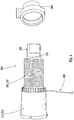
- an improved operating system 200 ( FIG. 5 ) is disclosed.
- the operating system 200 includes, inter alia, a housing 202, a drive mechanism 210 (e.g., drive spool 212 ), a clutch mechanism 220 (e.g., wrap spring 222 ), a driven member 230, an operating element 240, and an output assembly 250.
- the operating system 200 including the housing 202, the drive mechanism 210 (e.g., drive spool 212 ), the clutch mechanism 220 (e.g., wrap spring 222 ), the driven member 230, the operating element 240, and the output assembly 250, are substantially similar to the housing 102, the drive mechanism 110 (e.g., drive spool 112 ), the clutch mechanism 120 (e.g., wrap spring 122 ), the driven member 130, the operating element 140, and the output assembly 150 described above in connection with FIGS. 1 and 2 except as described herein.
- the housing 202 As such, detailed description of the housing 202, the drive mechanism 210 (e.g., drive spool 212 ), the clutch mechanism 220 (e.g., wrap spring 222 ), the driven member 230, the operating element 240, and the output assembly 250 are omitted for the sake of brevity.
- the drive mechanism 210 e.g., drive spool 212
- the clutch mechanism 220 e.g., wrap spring 222
- the driven member 230 As such, detailed description of the housing 202, the drive mechanism 210 (e.g., drive spool 212 ), the clutch mechanism 220 (e.g., wrap spring 222 ), the driven member 230, the operating element 240, and the output assembly 250 are omitted for the sake of brevity.
- the operating system 200 includes a bushing, a collar, or the like 300 (collectively referred to as a collar herein without the intent to limit).
- the collar 300 is adapted and configured to receive an end portion 224 of the wrap spring 222, for example, the end portion 224 including a tail 225 of the wrap spring 222, so that the edge of the wrap spring 222 is covered and thereby shielded from contacting, for example, the first and second housing portions of the operating system 200. That is, in one embodiment, the collar 300 is adapted and configured to receive an end portion 224 of the wrap spring 222 so that the end portion 224 of the wrap spring 222 is encased or enclosed by the collar 300.
- incorporation of the collar 300 facilitates manufacturing of the collar 300 from a first lubricated material while enabling the housing 202 of the operating system 200 to be manufactured from a second lubricated material.
- the collar 300 can be manufactured from a higher lubricated grade of material while enabling the housing 202 to be manufactured from a lesser lubricated grade of material, and thus a less expensive material.
- the housing 202 may be manufactured from a non-lubricated material.
- the collar 300 ensures that proper friction/drag with the wrap spring 222 is achieved to ensure proper operation of the operating system 200.
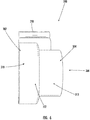
- the collar 300 includes a first end 302, a second end 304, and a through bore 306 extending from the first end 302 to the second end 304.
- the through bore 306 is adapted and configured to enable the driven member 230 to pass through so that the driven member 230 may be coupled, either directly or indirectly, to the rotatable member (schematically illustrated as 260 ).
- the collar 300 may include a first segment 310 adjacent to the first end 302 thereof and a second segment 312 adjacent to the second end 304 thereof.
- the first segment 310 may be diametrically larger than the second segment 312. That is, the first segment 310 has a first diameter and the second segment 312 has a second diameter, the first diameter being larger than the second diameter.
- an internally protruding shoulder 316 FIG. 7 ) may be formed in the through bore 306 between the larger diameter first segment 310 and the smaller diameter second segment 312. In use, the internally protruding shoulder 316 creates a stop or resting surface for the end portion 224 of the wrap spring 222. Meanwhile, as illustrated in FIGS.
- the through bore 306 enables the driven member 230 to pass therethrough.
- the first segment 310 may include an inner surface 318.
- the inner surface 318 has a smooth surface for contacting the wrap spring 222. In this manner, due to the lubrication of the collar 300, minimal friction exists between the inner surface 318 of the collar 300 and the wrap spring 222.
- the collar 300 may be keyed to the housing 202 (e.g., first housing portion 204 ) so that the collar 300 is prevented from rotation relative to the first housing portion 204.
- the collar 300 may include a projection 320 extending from an outer surface 322 thereof for interacting with the first housing portion 204 to prevent relative rotation between the collar 300 and the first housing portion 204 so that, in use, relative rotation of the drive spool 212 via pulling the operating element 240 causes, inter alia, the wrap spring 222 to tension. That is, in use, the collar 300 is adapted and configured to be seated within the first housing portion 204. For example, as illustrated in FIG. 5 , the second segment 312 of the collar 300 may be received within a corresponding arcuate seat 205 formed in the first housing portion 204.
- the seat 205 provides increased support of the collar 300, drive spool 212, driven member 230, and wrap spring 222 thus resulting in less bending of the overall assembly of components.
- the projection 320 formed on the collar 300 may contact a corresponding groove 206 formed in the first housing portion 204.
- rotation of the drive spool 212 in a first (e.g., counter-clockwise) direction via, for example, pulling on the operating element 240 causes the wrap spring 222 to rotate, which causes the wrap spring 222 to tension or tighten (e.g., wind up or clamp down) about an outer circumference of the drive spool 212 and an outer circumference of the driven member 230 so that rotation of the drive spool 212 rotates the driven member 230 (e.g., the drive spool 212,the wrap spring 222, and the driven member 230 rotate in unison).
- rotation of the drive spool 212 in a second (e.g., clockwise) direction via, for example, by releasing the operating element 240, causes the wrap spring 222 to un-tension or loosen (e.g., unwind or release) from the outer circumference of the drive spool 212 and the outer circumference of the driven member 230 so that reverse rotation of the drive spool 212 is not transferred to the driven member 230 (e.g., the drive spool 212 rotates relative to the wrap spring 222 and the driven member 230 so that rotation of the drive spool 212 is not transferred to the wrap spring 222 and the driven member 230 ).
- the wrap spring 222 un-tension or loosen (e.g., unwind or release) from the outer circumference of the drive spool 212 and the outer circumference of the driven member 230 so that reverse rotation of the drive spool 212 is not transferred to the driven member 230 (e.g., the drive spool 212 rotates relative to the wrap spring 222 and
- rotation of the drive spool 212 in the first direction causes the wrap spring 222 to rotate and tension, which causes the wrap spring 222 to constrict about the drive spool 212 so that rotation is transferred between the drive spool 212 and the driven member 230.
- Rotation of the drive spool 212 in the second direction causes the wrap spring 222 to come out of tension and thus expand slightly, allowing the drive spool 212 to rotate inside of and relative to the wrap spring 222 so that rotation is not transferred between the drive spool 212 and the driven member 230.
- wrap springs and one type of clutch mechanism have been discussed, other suitable elements may be used.
- the example operating system may be used with any type of shade, including, but not limited to, roller and stackable shades.
- the example operating module or system may be used in association with either end of a head rail. Accordingly, the discussion of any embodiment is meant only to be explanatory and is not intended to suggest that the scope of the disclosure, including the claims, is limited to these examples.
- inventive concepts may be otherwise variously embodied and employed, and that the appended claims are intended to be construed to include such variations, except as limited by the prior art.
- each of the expressions “at least one of A, B and C”, “at least one of A, B, or C”, “one or more of A, B, and C", “one or more of A, B, or C" and "A, B, and/or C” means A alone, B alone, C alone, A and B together, A and C together, B and C together, or A, B and C together.
- All directional references e.g., proximal, distal, upper, lower, upward, downward, left, right, lateral, longitudinal, front, back, top, bottom, above, below, vertical, horizontal, radial, axial, clockwise, and counterclockwise
- Connection references e.g., attached, coupled, connected, and joined
- connection references are to be construed broadly and may include intermediate members between a collection of elements and relative movement between elements unless otherwise indicated. As such, connection references do not necessarily infer that two elements are directly connected and in fixed relation to each other.
Landscapes
- Engineering & Computer Science (AREA)
- Structural Engineering (AREA)
- Architecture (AREA)
- Civil Engineering (AREA)
- General Engineering & Computer Science (AREA)
- Physics & Mathematics (AREA)
- Electromagnetism (AREA)
- Mechanical Engineering (AREA)
- Operating, Guiding And Securing Of Roll- Type Closing Members (AREA)
- Tents Or Canopies (AREA)
Applications Claiming Priority (1)
| Application Number | Priority Date | Filing Date | Title |
|---|---|---|---|
| US201962813898P | 2019-03-05 | 2019-03-05 |
Publications (3)
| Publication Number | Publication Date |
|---|---|
| EP3705678A2 true EP3705678A2 (de) | 2020-09-09 |
| EP3705678A3 EP3705678A3 (de) | 2021-01-27 |
| EP3705678B1 EP3705678B1 (de) | 2024-10-02 |
Family
ID=69770518
Family Applications (1)
| Application Number | Title | Priority Date | Filing Date |
|---|---|---|---|
| EP20160739.7A Active EP3705678B1 (de) | 2019-03-05 | 2020-03-03 | Bedienungssystem für eine architektonische strukturabdeckung |
Country Status (5)
| Country | Link |
|---|---|
| US (1) | US20200284094A1 (de) |
| EP (1) | EP3705678B1 (de) |
| AU (1) | AU2020201613B2 (de) |
| CA (1) | CA3074382A1 (de) |
| DK (1) | DK3705678T3 (de) |
Families Citing this family (2)
| Publication number | Priority date | Publication date | Assignee | Title |
|---|---|---|---|---|
| WO2024158567A1 (en) | 2023-01-26 | 2024-08-02 | Hunter Douglas Inc. | Wand assembly for use with a retractable pull cord system in an architectural-structure covering |
| CN116177433A (zh) * | 2023-03-07 | 2023-05-30 | 湖南墨达智能科技有限公司 | 一种卷扬机构 |
Citations (5)
| Publication number | Priority date | Publication date | Assignee | Title |
|---|---|---|---|---|
| US6129131A (en) | 1997-11-26 | 2000-10-10 | Hunter Douglas Inc. | Control system for coverings for architectural openings |
| US6158563A (en) | 1998-07-15 | 2000-12-12 | Hunter Douglas International N.V. | Winding mechanism |
| US20180106106A1 (en) | 2016-10-17 | 2018-04-19 | Coulisse B.V. | Universal operating device for a screen, such as a window covering |
| WO2018178728A1 (en) | 2017-03-31 | 2018-10-04 | Louver-Lite Limited | A control assembly for a window blind |
| US10107032B2 (en) | 2016-01-29 | 2018-10-23 | Nien Made Enterprise Co., Ltd. | Control mechanism for raising and lowering window covering |
Family Cites Families (1)
| Publication number | Priority date | Publication date | Assignee | Title |
|---|---|---|---|---|
| JP5242510B2 (ja) * | 2009-07-02 | 2013-07-24 | トックベアリング株式会社 | 逆入力遮断機構 |
-
2020
- 2020-02-20 US US16/795,941 patent/US20200284094A1/en not_active Abandoned
- 2020-03-03 DK DK20160739.7T patent/DK3705678T3/da active
- 2020-03-03 EP EP20160739.7A patent/EP3705678B1/de active Active
- 2020-03-04 AU AU2020201613A patent/AU2020201613B2/en active Active
- 2020-03-04 CA CA3074382A patent/CA3074382A1/en active Pending
Patent Citations (5)
| Publication number | Priority date | Publication date | Assignee | Title |
|---|---|---|---|---|
| US6129131A (en) | 1997-11-26 | 2000-10-10 | Hunter Douglas Inc. | Control system for coverings for architectural openings |
| US6158563A (en) | 1998-07-15 | 2000-12-12 | Hunter Douglas International N.V. | Winding mechanism |
| US10107032B2 (en) | 2016-01-29 | 2018-10-23 | Nien Made Enterprise Co., Ltd. | Control mechanism for raising and lowering window covering |
| US20180106106A1 (en) | 2016-10-17 | 2018-04-19 | Coulisse B.V. | Universal operating device for a screen, such as a window covering |
| WO2018178728A1 (en) | 2017-03-31 | 2018-10-04 | Louver-Lite Limited | A control assembly for a window blind |
Also Published As
| Publication number | Publication date |
|---|---|
| EP3705678B1 (de) | 2024-10-02 |
| EP3705678A3 (de) | 2021-01-27 |
| US20200284094A1 (en) | 2020-09-10 |
| CA3074382A1 (en) | 2020-09-05 |
| DK3705678T3 (da) | 2024-10-28 |
| AU2020201613A1 (en) | 2020-09-24 |
| AU2020201613B2 (en) | 2025-11-20 |
Similar Documents
| Publication | Publication Date | Title |
|---|---|---|
| US12116841B2 (en) | Operating system for a covering for an architectural opening | |
| US9127500B2 (en) | Cord-winding device for venetian blind | |
| US9078537B2 (en) | Single cordless control for window covering | |
| US6918424B2 (en) | Cord winding device for a blind | |
| US7159635B2 (en) | Lift cord spool for coverings for architectural openings | |
| AU9137798A (en) | Control system for coverings for architectural openings | |
| AU2020201613B2 (en) | Operating system for an architectural-structure covering | |
| CN106437470A (zh) | 用于窗户遮盖物的偏斜调整机构 | |
| EP3461987A2 (de) | Bedienungssystem für eine abdeckung einer architektonischen struktur | |
| CN101426999A (zh) | 用于解开窗户绳的机构 | |
| US20240167333A1 (en) | Track system for use with an operating element in an architectural-structure covering | |
| US20210324678A1 (en) | Barrier layer for an architectural-structure covering | |
| US20190234140A1 (en) | Operating Device for a Pleated Blind | |
| AU2019213349B2 (en) | Operating Mechanism for a Covering for an Architectural Opening | |
| EP3902969B1 (de) | Betätigungsmechanismus für eine fensterabdeckung und fensterabdeckung | |
| JP5376708B2 (ja) | 日射遮蔽装置の操作装置 | |
| US20070125502A1 (en) | Window blind structure | |
| US20260055659A1 (en) | Brake assembly with an over running gear for an architectural structure covering | |
| JP4256225B2 (ja) | 日射遮蔽装置の遮蔽材昇降装置及び日射遮蔽装置 | |
| TW202447064A (zh) | 與建築結構覆蓋物中之可伸縮拉繩系統一起使用之棒總成 | |
| AU2021387669A9 (en) | A brake assembly for an architectural structure covering | |
| JP2018071347A (ja) | 建築物開口部用の覆いのためのオペレーティングシステム |
Legal Events
| Date | Code | Title | Description |
|---|---|---|---|
| PUAI | Public reference made under article 153(3) epc to a published international application that has entered the european phase |
Free format text: ORIGINAL CODE: 0009012 |
|
| STAA | Information on the status of an ep patent application or granted ep patent |
Free format text: STATUS: THE APPLICATION HAS BEEN PUBLISHED |
|
| AK | Designated contracting states |
Kind code of ref document: A2 Designated state(s): AL AT BE BG CH CY CZ DE DK EE ES FI FR GB GR HR HU IE IS IT LI LT LU LV MC MK MT NL NO PL PT RO RS SE SI SK SM TR |
|
| AX | Request for extension of the european patent |
Extension state: BA ME |
|
| PUAL | Search report despatched |
Free format text: ORIGINAL CODE: 0009013 |
|
| AK | Designated contracting states |
Kind code of ref document: A3 Designated state(s): AL AT BE BG CH CY CZ DE DK EE ES FI FR GB GR HR HU IE IS IT LI LT LU LV MC MK MT NL NO PL PT RO RS SE SI SK SM TR |
|
| AX | Request for extension of the european patent |
Extension state: BA ME |
|
| RIC1 | Information provided on ipc code assigned before grant |
Ipc: E06B 9/78 20060101ALI20201222BHEP Ipc: F16D 13/08 20060101ALI20201222BHEP Ipc: E06B 9/322 20060101AFI20201222BHEP |
|
| TPAC | Observations filed by third parties |
Free format text: ORIGINAL CODE: EPIDOSNTIPA |
|
| STAA | Information on the status of an ep patent application or granted ep patent |
Free format text: STATUS: REQUEST FOR EXAMINATION WAS MADE |
|
| 17P | Request for examination filed |
Effective date: 20210720 |
|
| RBV | Designated contracting states (corrected) |
Designated state(s): AL AT BE BG CH CY CZ DE DK EE ES FI FR GB GR HR HU IE IS IT LI LT LU LV MC MK MT NL NO PL PT RO RS SE SI SK SM TR |
|
| GRAP | Despatch of communication of intention to grant a patent |
Free format text: ORIGINAL CODE: EPIDOSNIGR1 |
|
| STAA | Information on the status of an ep patent application or granted ep patent |
Free format text: STATUS: GRANT OF PATENT IS INTENDED |
|
| INTG | Intention to grant announced |
Effective date: 20240422 |
|
| GRAS | Grant fee paid |
Free format text: ORIGINAL CODE: EPIDOSNIGR3 |
|
| GRAA | (expected) grant |
Free format text: ORIGINAL CODE: 0009210 |
|
| STAA | Information on the status of an ep patent application or granted ep patent |
Free format text: STATUS: THE PATENT HAS BEEN GRANTED |
|
| RAP3 | Party data changed (applicant data changed or rights of an application transferred) |
Owner name: HUNTER DOUGLAS INC. |
|
| P01 | Opt-out of the competence of the unified patent court (upc) registered |
Free format text: CASE NUMBER: APP_47908/2024 Effective date: 20240820 |
|
| AK | Designated contracting states |
Kind code of ref document: B1 Designated state(s): AL AT BE BG CH CY CZ DE DK EE ES FI FR GB GR HR HU IE IS IT LI LT LU LV MC MK MT NL NO PL PT RO RS SE SI SK SM TR |
|
| REG | Reference to a national code |
Ref country code: GB Ref legal event code: FG4D |
|
| REG | Reference to a national code |
Ref country code: CH Ref legal event code: EP |
|
| REG | Reference to a national code |
Ref country code: DE Ref legal event code: R096 Ref document number: 602020038562 Country of ref document: DE |
|
| REG | Reference to a national code |
Ref country code: IE Ref legal event code: FG4D |
|
| REG | Reference to a national code |
Ref country code: DK Ref legal event code: T3 Effective date: 20241025 |
|
| REG | Reference to a national code |
Ref country code: NL Ref legal event code: FP |
|
| REG | Reference to a national code |
Ref country code: SE Ref legal event code: TRGR |
|
| REG | Reference to a national code |
Ref country code: LT Ref legal event code: MG9D |
|
| PG25 | Lapsed in a contracting state [announced via postgrant information from national office to epo] |
Ref country code: HR Free format text: LAPSE BECAUSE OF FAILURE TO SUBMIT A TRANSLATION OF THE DESCRIPTION OR TO PAY THE FEE WITHIN THE PRESCRIBED TIME-LIMIT Effective date: 20241002 Ref country code: PT Free format text: LAPSE BECAUSE OF FAILURE TO SUBMIT A TRANSLATION OF THE DESCRIPTION OR TO PAY THE FEE WITHIN THE PRESCRIBED TIME-LIMIT Effective date: 20250203 Ref country code: IS Free format text: LAPSE BECAUSE OF FAILURE TO SUBMIT A TRANSLATION OF THE DESCRIPTION OR TO PAY THE FEE WITHIN THE PRESCRIBED TIME-LIMIT Effective date: 20250202 |
|
| PG25 | Lapsed in a contracting state [announced via postgrant information from national office to epo] |
Ref country code: FI Free format text: LAPSE BECAUSE OF FAILURE TO SUBMIT A TRANSLATION OF THE DESCRIPTION OR TO PAY THE FEE WITHIN THE PRESCRIBED TIME-LIMIT Effective date: 20241002 |
|
| PG25 | Lapsed in a contracting state [announced via postgrant information from national office to epo] |
Ref country code: BG Free format text: LAPSE BECAUSE OF FAILURE TO SUBMIT A TRANSLATION OF THE DESCRIPTION OR TO PAY THE FEE WITHIN THE PRESCRIBED TIME-LIMIT Effective date: 20241002 |
|
| PG25 | Lapsed in a contracting state [announced via postgrant information from national office to epo] |
Ref country code: ES Free format text: LAPSE BECAUSE OF FAILURE TO SUBMIT A TRANSLATION OF THE DESCRIPTION OR TO PAY THE FEE WITHIN THE PRESCRIBED TIME-LIMIT Effective date: 20241002 |
|
| PG25 | Lapsed in a contracting state [announced via postgrant information from national office to epo] |
Ref country code: LV Free format text: LAPSE BECAUSE OF FAILURE TO SUBMIT A TRANSLATION OF THE DESCRIPTION OR TO PAY THE FEE WITHIN THE PRESCRIBED TIME-LIMIT Effective date: 20241002 Ref country code: GR Free format text: LAPSE BECAUSE OF FAILURE TO SUBMIT A TRANSLATION OF THE DESCRIPTION OR TO PAY THE FEE WITHIN THE PRESCRIBED TIME-LIMIT Effective date: 20250103 |
|
| PG25 | Lapsed in a contracting state [announced via postgrant information from national office to epo] |
Ref country code: PL Free format text: LAPSE BECAUSE OF FAILURE TO SUBMIT A TRANSLATION OF THE DESCRIPTION OR TO PAY THE FEE WITHIN THE PRESCRIBED TIME-LIMIT Effective date: 20241002 Ref country code: CZ Free format text: LAPSE BECAUSE OF FAILURE TO SUBMIT A TRANSLATION OF THE DESCRIPTION OR TO PAY THE FEE WITHIN THE PRESCRIBED TIME-LIMIT Effective date: 20241002 |
|
| PG25 | Lapsed in a contracting state [announced via postgrant information from national office to epo] |
Ref country code: RS Free format text: LAPSE BECAUSE OF FAILURE TO SUBMIT A TRANSLATION OF THE DESCRIPTION OR TO PAY THE FEE WITHIN THE PRESCRIBED TIME-LIMIT Effective date: 20250102 |
|
| PG25 | Lapsed in a contracting state [announced via postgrant information from national office to epo] |
Ref country code: SM Free format text: LAPSE BECAUSE OF FAILURE TO SUBMIT A TRANSLATION OF THE DESCRIPTION OR TO PAY THE FEE WITHIN THE PRESCRIBED TIME-LIMIT Effective date: 20241002 |
|
| REG | Reference to a national code |
Ref country code: DE Ref legal event code: R097 Ref document number: 602020038562 Country of ref document: DE |
|
| PG25 | Lapsed in a contracting state [announced via postgrant information from national office to epo] |
Ref country code: EE Free format text: LAPSE BECAUSE OF FAILURE TO SUBMIT A TRANSLATION OF THE DESCRIPTION OR TO PAY THE FEE WITHIN THE PRESCRIBED TIME-LIMIT Effective date: 20241002 |
|
| PG25 | Lapsed in a contracting state [announced via postgrant information from national office to epo] |
Ref country code: RO Free format text: LAPSE BECAUSE OF FAILURE TO SUBMIT A TRANSLATION OF THE DESCRIPTION OR TO PAY THE FEE WITHIN THE PRESCRIBED TIME-LIMIT Effective date: 20241002 |
|
| PG25 | Lapsed in a contracting state [announced via postgrant information from national office to epo] |
Ref country code: SK Free format text: LAPSE BECAUSE OF FAILURE TO SUBMIT A TRANSLATION OF THE DESCRIPTION OR TO PAY THE FEE WITHIN THE PRESCRIBED TIME-LIMIT Effective date: 20241002 |
|
| PG25 | Lapsed in a contracting state [announced via postgrant information from national office to epo] |
Ref country code: IT Free format text: LAPSE BECAUSE OF FAILURE TO SUBMIT A TRANSLATION OF THE DESCRIPTION OR TO PAY THE FEE WITHIN THE PRESCRIBED TIME-LIMIT Effective date: 20241002 |
|
| PLBE | No opposition filed within time limit |
Free format text: ORIGINAL CODE: 0009261 |
|
| STAA | Information on the status of an ep patent application or granted ep patent |
Free format text: STATUS: NO OPPOSITION FILED WITHIN TIME LIMIT |
|
| 26N | No opposition filed |
Effective date: 20250703 |
|
| PG25 | Lapsed in a contracting state [announced via postgrant information from national office to epo] |
Ref country code: MC Free format text: LAPSE BECAUSE OF FAILURE TO SUBMIT A TRANSLATION OF THE DESCRIPTION OR TO PAY THE FEE WITHIN THE PRESCRIBED TIME-LIMIT Effective date: 20241002 |
|
| REG | Reference to a national code |
Ref country code: AT Ref legal event code: UEP Ref document number: 1728629 Country of ref document: AT Kind code of ref document: T Effective date: 20241002 |
|
| REG | Reference to a national code |
Ref country code: CH Ref legal event code: H13 Free format text: ST27 STATUS EVENT CODE: U-0-0-H10-H13 (AS PROVIDED BY THE NATIONAL OFFICE) Effective date: 20251023 |
|
| PG25 | Lapsed in a contracting state [announced via postgrant information from national office to epo] |
Ref country code: LU Free format text: LAPSE BECAUSE OF NON-PAYMENT OF DUE FEES Effective date: 20250303 |
|
| REG | Reference to a national code |
Ref country code: BE Ref legal event code: MM Effective date: 20250331 |
|
| PG25 | Lapsed in a contracting state [announced via postgrant information from national office to epo] |
Ref country code: FR Free format text: LAPSE BECAUSE OF NON-PAYMENT OF DUE FEES Effective date: 20250331 |
|
| PG25 | Lapsed in a contracting state [announced via postgrant information from national office to epo] |
Ref country code: BE Free format text: LAPSE BECAUSE OF NON-PAYMENT OF DUE FEES Effective date: 20250331 |
|
| PG25 | Lapsed in a contracting state [announced via postgrant information from national office to epo] |
Ref country code: CH Free format text: LAPSE BECAUSE OF NON-PAYMENT OF DUE FEES Effective date: 20250331 |
|
| PG25 | Lapsed in a contracting state [announced via postgrant information from national office to epo] |
Ref country code: IE Free format text: LAPSE BECAUSE OF NON-PAYMENT OF DUE FEES Effective date: 20250303 |
|
| PGFP | Annual fee paid to national office [announced via postgrant information from national office to epo] |
Ref country code: SE Payment date: 20260323 Year of fee payment: 7 |
|
| PGFP | Annual fee paid to national office [announced via postgrant information from national office to epo] |
Ref country code: GB Payment date: 20260319 Year of fee payment: 7 |
|
| PGFP | Annual fee paid to national office [announced via postgrant information from national office to epo] |
Ref country code: DE Payment date: 20260320 Year of fee payment: 7 Ref country code: DK Payment date: 20260323 Year of fee payment: 7 Ref country code: NO Payment date: 20260318 Year of fee payment: 7 |
|
| PGFP | Annual fee paid to national office [announced via postgrant information from national office to epo] |
Ref country code: AT Payment date: 20260318 Year of fee payment: 7 |
|
| PGFP | Annual fee paid to national office [announced via postgrant information from national office to epo] |
Ref country code: NL Payment date: 20260323 Year of fee payment: 7 |