EP3705608A1 - Electrolytically sn-plated steel sheet - Google Patents
Electrolytically sn-plated steel sheet Download PDFInfo
- Publication number
- EP3705608A1 EP3705608A1 EP18873736.5A EP18873736A EP3705608A1 EP 3705608 A1 EP3705608 A1 EP 3705608A1 EP 18873736 A EP18873736 A EP 18873736A EP 3705608 A1 EP3705608 A1 EP 3705608A1
- Authority
- EP
- European Patent Office
- Prior art keywords
- electrolytic
- content
- layer
- plated
- steel sheet
- Prior art date
- Legal status (The legal status is an assumption and is not a legal conclusion. Google has not performed a legal analysis and makes no representation as to the accuracy of the status listed.)
- Granted
Links
Images

Classifications
-
- C—CHEMISTRY; METALLURGY
- C25—ELECTROLYTIC OR ELECTROPHORETIC PROCESSES; APPARATUS THEREFOR
- C25D—PROCESSES FOR THE ELECTROLYTIC OR ELECTROPHORETIC PRODUCTION OF COATINGS; ELECTROFORMING; APPARATUS THEREFOR
- C25D21/00—Processes for servicing or operating cells for electrolytic coating
- C25D21/16—Regeneration of process solutions
- C25D21/18—Regeneration of process solutions of electrolytes
-
- C—CHEMISTRY; METALLURGY
- C25—ELECTROLYTIC OR ELECTROPHORETIC PROCESSES; APPARATUS THEREFOR
- C25D—PROCESSES FOR THE ELECTROLYTIC OR ELECTROPHORETIC PRODUCTION OF COATINGS; ELECTROFORMING; APPARATUS THEREFOR
- C25D3/00—Electroplating: Baths therefor
- C25D3/02—Electroplating: Baths therefor from solutions
- C25D3/30—Electroplating: Baths therefor from solutions of tin
- C25D3/32—Electroplating: Baths therefor from solutions of tin characterised by the organic bath constituents used
-
- C—CHEMISTRY; METALLURGY
- C25—ELECTROLYTIC OR ELECTROPHORETIC PROCESSES; APPARATUS THEREFOR
- C25D—PROCESSES FOR THE ELECTROLYTIC OR ELECTROPHORETIC PRODUCTION OF COATINGS; ELECTROFORMING; APPARATUS THEREFOR
- C25D7/00—Electroplating characterised by the article coated
- C25D7/06—Wires; Strips; Foils
- C25D7/0614—Strips or foils
-
- C—CHEMISTRY; METALLURGY
- C25—ELECTROLYTIC OR ELECTROPHORETIC PROCESSES; APPARATUS THEREFOR
- C25D—PROCESSES FOR THE ELECTROLYTIC OR ELECTROPHORETIC PRODUCTION OF COATINGS; ELECTROFORMING; APPARATUS THEREFOR
- C25D5/00—Electroplating characterised by the process; Pretreatment or after-treatment of workpieces
- C25D5/48—After-treatment of electroplated surfaces
- C25D5/50—After-treatment of electroplated surfaces by heat-treatment
- C25D5/505—After-treatment of electroplated surfaces by heat-treatment of electroplated tin coatings, e.g. by melting
Definitions
- the present invention relates to an electrolytic Sn-plated steel sheet, and particularly, to an electrolytic Sn-plated steel sheet having a low Pb content in a whole electrolytic Sn-plated layer.
- tin can material a Sn-plated steel sheet which is used for food canning.
- Pb content in a Sn-plated layer is required to be 100 ppm by mass or less in view of the regulation of Pb 2+ eluted in a can, and introduction of similar regulations has been considered in some European countries or in China. Demands similar to the above description have also been made from some customers.
- Sn ingots which are used for plating of a Sn-plated steel sheet are imported from Southeast Asian countries. Since the Pb content of the raw ore is large, the Sn ingots produced in Southeast Asia contain 100 ppm by mass or greater of Pb. In a case where the Sn ingots produced in Southeast Asia are used as they are, the Pb content in a Sn-plated layer of a Sn-plated steel sheet as a product cannot be adjusted to 100 ppm by mass or less. Accordingly, in a case where Sn ingots produced in Southeast Asia are used, electrolytic refining is performed even with an increase in the producing cost, to secure a level at which the current regulation value is somewhat satisfied.
- Sn ingots produced in South America which have a small Pb content, are purchased even with an increase in the transport cost due to a long transport distance, to cope with the problems caused by the above regulation.
- the Pb content is about 70 ppm by mass, and this is at a level at which the current regulation value is somewhat satisfied.
- Patent Document 1 describes an invention relating to an electrolytic refining method for high-purity Sn, in which a Sn electrolytic solution consisting of a fluorosilicic acid or a mixed acid of a sulfuric acid and a fluorosilicic acid is extracted from an electrolysis tank, a carbonate of an alkaline earth metal is added to the electrolytic solution to precipitate Pb in the solution, the electrolytic solution from which the precipitate is removed is returned to the electrolysis tank to perform electrolytic refining of Sn.
- Patent Document 1 has no description about the Pb content in a Sn-plated steel sheet and in a Sn-plated layer.
- Patent Document 2 describes a technique in which a workpiece made of a pure metal or an alloy is heated and melted, and at least one of a metal halide or an oxyhalide is brought into contact with the melt to remove Pb in the workpiece.
- Patent Document 2 only Pb-free solder is described as a specific workpiece, and there is no description about the Pb content in a Sn-plated layer of a Sn-plated steel sheet.
- Patent Document 3 describes an invention in which an angle formed between adjacent grain boundaries in a Sn-plated layer is adjusted to 20° or less in order to prevent a short circuit between terminals due to the growth of whisker that is likely to occur in a case where Pb-free Sn plating is performed on an electronic component such as a semiconductor device.
- Patent Document 3 does not describe a method of producing Sn plating having an extremely low Pb concentration from a coating bath containing Pb.
- an object of the invention is to provide an electrolytic Sn-plated steel sheet which has a Pb content of 50 ppm by mass or less in a whole electrolytic Sn-plated layer and is applicable as a steel sheet for a container. More specifically, an object of the invention is to provide an electrolytic Sn-plated steel sheet which has a long life and has excellent corrosion resistance, coating film adhesion, and whisker resistance in a case where the steel sheet is applied as a steel sheet for a container.
- the gist of the invention is as follows.
- an electrolytic Sn-plated steel sheet which has a Pb content of 50 ppm by mass or less in a whole electrolytic Sn-plated layer and is applicable as a steel sheet for a container.
- An electrolytic Sn-plated steel sheet includes: a base steel sheet; and an electrolytic Sn-plated layer which is disposed on the base steel sheet, has a Sn layer and an alloy layer, and contains Sn: 10 to 100 mass%, Fe: 0 to 90 mass%, and O: 0 to 0.5 mass%, the Pb content of the whole electrolytic Sn-plated layer is 50 ppm by mass or less, and in a case where the thickness of the electrolytic Sn-plated layer is represented by t and a region from a surface of the electrolytic Sn-plated layer to a depth of (1/10) ⁇ t in a sheet thickness direction is defined as a surface layer region, the Pb content of the surface layer region is 5 ppm by mass or greater and the Pb content of the surface layer region is higher than the Pb content of the whole electrolytic Sn-plated layer.
- the inventors have investigated the mechanism in which Pb contained in a Sn ingot is mixed in the electrolytic Sn-plated layer.
- the inventors have found from the observation and quantitative measurement of the electrolytic Sn-plated layer in the depth direction that Pb exists as metal Pb in the whole electrolytic Sn-plated layer, that is, Pb is electrolytically deposited (eutectoid) together with Sn and is not contained in the electrolytic Sn-plated layer by mere involvement of a Sn plating solution.
- the inventors prepared a Sn plating solution (PSA coating bath) including a p-phenolsulfonic acid, a Sn (II) sulfate, and additives, and a Pb-containing plating solution obtained by adding a Pb acetate to the Sn plating solution, and formed an electrolytic Sn-plated layer by changing a set potential.
- PSA coating bath including a p-phenolsulfonic acid, a Sn (II) sulfate, and additives
- Pb-containing plating solution obtained by adding a Pb acetate to the Sn plating solution, and formed an electrolytic Sn-plated layer by changing a set potential.
- the inventors have found that there is almost no difference in the deposition potential between Sn and Pb, and that in a case where a Sn ingot having a low Pb content (about 50 ppm by mass) is used as a Sn source, the Pb content in the electrolytic Sn-plated layer can be adjusted to 100 ppm by mass or less (about 70 ppm by mass), and in a case where a Sn ingot having a high Pb content (about 100 to 300 ppm by mass) is used, it is difficult to suppress eutectoid of Pb by changing the plating conditions such as a current density with the use of the Sn plating solution which is used in an actual operation.
- the Sn plating solution which is used in the plating step of the electrolytic Sn-plated steel sheet supplies Sn 2+ in the form of a sulfuric acid bath using an insoluble anode, and the solubilities of the sulfates of Sn and Pb at 20°C are as follows.
- a crown ether is formed of a cyclic polyether chain and can selectively interact with several heavy metal ions.
- a crown ether has a vacancy formed by ether oxygen atoms in the molecule, and takes in a heavy metal ion and binds therewith. Accordingly, a selective interaction occurs in a case where the size of the heavy metal ion and the size of the vacancy in the crown ether match.
- a crown ether in which the size of the vacancy is adjusted to match the size of the lead ion may be used.
- a crown ether in which in the general structural formula (-CH 2 -CH 2 -O-) n of the crown ether, n is 6, and the size of a vacancy is controlled is supported on a resin (which is not particularly limited, and can be selected from, for example, silica gel, methacrylate, and polystyrene), a column is filled with the resin, and the Sn plating solution is allowed to pass through the column to selectively remove a lead ion (Pb 2+ ).
- a resin which is not particularly limited, and can be selected from, for example, silica gel, methacrylate, and polystyrene
- the Sn plating solution as a base contains p-phenolsulfonic acid: 115 g/L, ethoxylated ⁇ -naphthol (EN-10): 5 g / L, ethoxylated ⁇ -naphthol sulphonic acid (ENSA): 5 g/L, and SnSO 4 : 36 g/L (20 g/L in terms of Sn 2+ ), and Pb is added to the Sn plating solution in the form of a Pb acetate such that Pb is contained at a concentration of 13 mg/L (650 ppm in terms of Pb/Sn) in terms of Pb 2+
- a total of 200 L of the Sn plating solution was allowed to pass through a column filled with a crown ether, and component analysis was performed for each 20 L of the Sn plating solution passing through the column.
- FIG. 1 shows changes in the Pb 2+ concentration in the Sn plating solution.
- Pb 2+ contained at a concentration of 13 mg/L is immediately reduced to 0.05 mg/L, and thus it is found that Pb 2+ in the Sn coating bath is removed by the crown ether.
- concentrations of other components (Sn 2+ , SO 4 2- , ENSA, EN) in the Sn plating solution are hardly changed, it is thought that only Pb 2+ is selectively removed.
- the uniformity in the electrolytic Sn-plated layer is increased in order to secure stable productivity. Accordingly, the Pb content in the electrolytic Sn-plated layer is uniformly reduced in the depth direction.
- the inventors have newly found that unlike the prior art, the occurrence of staining is reduced by reducing the Pb content of the whole electrolytic Sn-plated layer, and whisker resistance is improved by concentrating Pb in the surface layer region.
- coating film adhesion is improved by imparting a gradient to the Pb content in the electrolytic Sn-plated layer.
- the electrolytic Sn-plated steel sheet according to this embodiment is provided based on the above knowledge. Hereinafter, the electrolytic Sn-plated steel sheet according to this embodiment will be described in detail.
- a base steel sheet of the electrolytic Sn-plated steel sheet according to this embodiment is not particularly limited, and a steel sheet which is used as a base steel sheet of a general steel sheet for a container specified in JIS G 3303: 2017 may be used.
- a base steel sheet containing C: 0.01 to 0.06 mass%, Al: 0.001 to 0.01 mass%, Mn: 0.01 to 0.06 mass%, and the remainder consisting of Fe and impurities can be used.
- An electrolytic Sn-plated layer has a Sn layer existing on the surface side of the electrolytic Sn-plated layer and containing a large amount of Sn, and an alloy layer (Fe-Sn layer) existing on the base steel sheet side of the electrolytic Sn-plated layer, in which Fe of the base steel sheet is diffused in the electrolytic Sn-plated layer.
- an alloy layer Fe-Sn layer
- the definitions of the electrolytic Sn-plated layer, the Sn layer, and the alloy layer will be described later.
- the Pb content of the whole electrolytic Sn-plated layer is 50 ppm by mass or less. In a case where the Pb content of the whole electrolytic Sn-plated layer is greater than 50 ppm by mass, the Pb content regulation value that is anticipated cannot be satisfied, and characteristics (long life, corrosion resistance) desired for a steel sheet for a container cannot be obtained.
- the Pb content of the whole electrolytic Sn-plated layer is preferably 40 ppm by mass or less, 30 ppm by mass or less, 20 ppm by mass or less, or 10 ppm by mass or less. Although it is possible to make the Pb content of the whole electrolytic Sn-plated layer less than 5 ppm by mass, this causes a cost increase in an actual operation. Accordingly, the lower limit of the Pb content of the whole electrolytic Sn-plated layer may be set to 5 ppm by mass.
- the Pb content of the surface layer region is 5 ppm by mass or greater, and the Pb content of the surface layer region is higher than the Pb content of the whole electrolytic Sn-plated layer.
- the upper limit of the Pb content of the surface layer region may be 60 ppm by mass.
- the surface layer region refers to a region from a surface of the electrolytic Sn-plated layer to a depth of (1/10) ⁇ t in a sheet thickness direction, in a case where the thickness of the electrolytic Sn-plated layer is represented by t.
- a region other than the surface layer region of the electrolytic Sn-plated layer is referred to as a deep region.
- the deep region of the electrolytic Sn-plated layer is a region ranging from the region from the surface of the electrolytic Sn-plated layer to the depth of (1/10) ⁇ t in the sheet thickness direction to the region at a depth t in the sheet thickness direction from the surface, in a case where the thickness of the electrolytic Sn-plated layer is represented by t.
- the coating film adhesion of the electrolytic Sn-plated steel sheet deteriorates.
- a value obtained by dividing (Pb content/(Sn content+Pb content)) of the surface layer region of the electrolytic Sn-plated layer by (Pb content/(Sn content+Pb content)) of the deep region of the electrolytic Sn-plated layer may be 1.1 or greater.
- the coating film adhesion of the electrolytic Sn-plated steel sheet can be further improved.
- the electrolytic Sn-plated layer according to this embodiment contains Sn: 10 to 100 mass%, Fe: 0 to 90 mass%, and O: 0 to 0.5 mass% as elements other than Pb.
- the remainder consists of impurities.
- the impurities mean elements which are mixed from the Sn ingot as a raw material or the producing environment, and are permitted within a range not adversely affecting the electrolytic Sn-plated steel sheet according to this embodiment.
- the electrolytic Sn-plated layer according to this embodiment may further optionally contain one or more of the group consisting of Ca: 0.1 to 10 ppm by mass, Sr: 0.1 to 10 ppm by mass, and Ba: 0.1 to 10 ppm by mass.
- the Pb content of the whole electrolytic Sn-plated layer can be further reduced in a case where the electrolytic Sn-plated layer contains one or more of the above group.
- the electrolytic Sn-plated steel sheet according to this embodiment may further include one or more of a Fe-Ni layer, a Ni-Sn layer, and a Fe-Ni-Sn layer between the electrolytic Sn-plated layer and the base steel sheet, strictly speaking, between the alloy layer (Fe-Sn layer) and the base steel sheet.
- the electrolytic Sn-plated layer further includes one or more of these layers, the can life can be extended in a case where the electrolytic Sn-plated steel sheet is used as a beverage can or a food can.
- a barrier effect is generated due to the formation of a dense alloy layer, corrosion resistance can be improved.
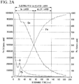
- FIG. 2A is a graph obtained by performing GD-MS analysis on an electrolytic Sn-plated steel sheet of No. 16 of Example.
- the graph of FIG. 2A shows changes in the contents of Fe, Sn, Pb, and O from the surface side of the electrolytic Sn-plated layer on the left end side of the horizontal axis toward the base steel sheet side on the right end side.
- the scale on the left side is for Fe and Sn
- the scale on the right side is for Pb and O.
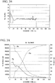
- the graph of FIG. 2B is obtained by acquiring the Sn content and the Pb content of FIG. 2A , calculating a value of Pb/(Sn+Pb), and making changes in the depth direction from the surface of the electrolytic Sn-plated layer into a graph.
- a region ranging from the surface to a region having a Sn content of 100,000 ppm or greater is defined as the electrolytic Sn-plated layer.
- the electrolytic Sn-plated layer a region where the Sn content is higher than the Fe content is defined as a Sn layer, and in the electrolytic Sn-plated layer, a region other than the Sn layer is defined as an alloy layer (Fe-Sn layer) (see FIG. 2A ).
- a region where the Fe content is 10 to 90 mass% and the Ni content is 10 to 90 mass% is defined as a Fe-Ni layer
- a region where the Ni content is 10 to 90 mass% and the Sn content is 10 to 90 mass% is defined as a Ni-Sn layer
- a region where the Fe content is 10 to 80 mass%, the Ni content is 10 to 80 mass%, and the Sn content is 10 to 80 mass% is defined as a Fe-Ni-Sn layer.
- the Pb content of the whole electrolytic Sn-plated layer is the Pb content of the whole electrolytic Sn-plated layer including the Sn layer and the alloy layer, obtained by GD-MS analysis.
- the Pb content of the surface layer region is the Pb content of a region from the surface of the electrolytic Sn-plated layer to a depth of (1/10) ⁇ t, obtained by GD-MS analysis.
- (Pb content/(Sn content+Pb content)) of the surface layer region of the electrolytic Sn-plated layer is obtained by dividing the Pb content (mass%) of the surface layer region by the sum of the Sn content (mass%) and the Pb content (mass%) of the surface layer region.
- (Pb content/(Sn content+Pb content)) of the deep region of the electrolytic Sn-plated layer is obtained by dividing the Pb content (mass%) of the deep region by the sum of the Sn content (mass%) and the Pb content (mass%) of the deep region.
- the Ca content, the Sr content, and the Ba content in the electrolytic Sn-plated layer are obtained by analyzing a solution, obtained by dissolving the electrolytic Sn-plated layer using an acid containing an inhibitor, by inductively coupled plasma-mass spectrometry (ICP-MS).
- ICP-MS inductively coupled plasma-mass spectrometry
- electrolytic Sn plating is applied to the base steel sheet having the above-described chemical composition.
- electrolytic Sn plating is performed using a Sn plating solution having a Pb 2+ concentration reduced by a crown ether method.
- Electrolytic degreasing may be performed before the electrolytic Sn plating.
- the current density of the first to ninth passes is made constant, and the current density of the 10th pass (final pass) is increased to perform the electrolytic Sn plating.
- the Pb content of the surface layer region of the electrolytic Sn-plated layer can be adjusted by adjusting the increase width of the current density of the 10th pass.
- flux coating is performed on the base steel sheet, followed by immersion in a 10-fold dilution of the Sn plating solution. After roller squeezing, cold air drying is performed, and energization heating and quenching (80°C) are performed as a reflow operation.
- the electrolytic Sn-plated steel sheet according to this embodiment can be produced.
- a carbonate of an alkaline earth metal (Ca, Sr, Ba) may be added to the Sn plating solution. Accordingly, the yield of Pb 2+ removal by the crown ether method can be improved, and the Pb content of the whole electrolytic Sn-plated layer can be further reduced.
- Ni pre-plating or Fe-Ni pre-plating may be performed as a pretreatment for electrolytic Sn plating. Accordingly, one or more of a Fe-Ni layer, a Ni-Sn layer, and a Fe-Ni-Sn layer can be formed between the base steel sheet and the electrolytic Sn-plated layer.
- Components of a Sn plating solution were as follows: Sn 2+ : 20 g/L; Pb 2+ : 5 mg/L (250 ppm in terms of Pb/Sn); EN: 5 g/L; ENSA: 5 g/L; and PSA: 100 g/L, and the temperature was 45°C.
- a column was filled with a resin on which a crown ether had been supported (silica gel was used in this Example), and the Sn plating solution was allowed to pass through the column.
- the Sn plating solution was moved to a plating cell, and returned to the column after circulation in the plating cell. The above operation was repeated.
- a flow rate (L/hr) of the Sn plating solution was set to 60 L/hr for 1 L of the resin although depending on a resin volume (L).
- the inventors have presumed that this is because the characteristics of the crown ether slightly deteriorate due to the presence of a large amount of pre-existing sludge (containing SnO 2 as a main component) in the actual operation line. However, it has been found that the effect can be sufficiently exhibited even in the actual operation line by adjusting the flow rate or the exchange frequency of the crown ether.
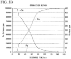
- FIG. 3B shows results of GD-MS analysis of an electrolytic Sn-plated layer produced using a Sn plating solution which contains Pb 2+ : 0.1 mg/L through the crown ether method.
- FIG. 3A shows results of GD-MS analysis of an electrolytic Sn-plated layer (comparative example) produced using a Sn plating solution subjected to no treatment.
- a steel sheet containing C: 0.03 mass%, Al: 0.005 mass%, Mn: 0.03 mass%, and the remainder consisting of Fe and impurities was used as a base steel sheet.
- Components of a Sn plating solution were as follows: Sn 2+ : 20 g/L; Pb 2+ : 5 mg/L (250 ppm in terms of Pb/Sn); EN: 5 g/L; ENSA: 5 g/L; and PSA: 100 g/L, and the temperature was 45°C.
- the Pb 2+ concentration of the Sn plating solution was reduced by a crown ether method, and an electrolytic Sn-plated layer was sequentially formed at an arbitrary Pb 2+ concentration through an electrolytic Sn plating step to be described later. It was possible to reduce the Pb 2+ concentration down to 0.05 mg/L in the laboratory scale.
- an electrolytic degreasing step of the steel sheet was performed in which a current of 10 A/dm 2 ⁇ 10 sec was allowed to flow such that the steel sheet was on the cathode side in a 10% NaOH solution at 60°C. Then, pickling was performed by dipping in 10% H 2 SO 4 at room temperature for 10 seconds, and then electrolytic Sn plating was performed at 5 A/dm 2 using the above Sn plating solution to achieve #25 tin (adhered amount of Sn on single side: 2.8 g/m 2 ).
- the current density of the final pass among the 10 passes was changed, and thus an electrolytic Sn-plated layer in which the distribution state of Pb was controlled was formed. That is, the current density of the final pass was increased to concentrate Pb in a surface layer region, and conversely, the current density of the final pass was reduced to make the Pb content of the surface layer region lower than the Pb content of the whole electrolytic Sn-plated layer.
- the current density was maintained at 20 A/dm 2 except for the final pass, and increased to 30 to 60 A/dm 2 in the final pass, and the electrolytic Sn plating was performed. However, in cases of No. 11 and No. 14 of Table 1, only the current density of the final pass was reduced, and in cases of No. 37 and No. 38, the current density was made constant.
- a carbonate of an alkaline earth metal (Ca, Sr, Ba) was added to some Sn plating solutions.
- Ni pre-plating or Fe-20 mass% Ni pre-plating was performed as a pretreatment for the electrolytic Sn plating step such that the adhered amount of Ni was 20 mg/m 2 . Then, a Fe-Ni layer, a Ni-Sn layer (mainly containing Ni 3 Sn 4 ), or a Fe-Ni-Sn layer was formed by reflow.
- Component analysis of the electrolytic Sn-plated layer was performed by the above-described method.
- GD-MS analysis a rectangular sample of 30 mm ⁇ 15 mm was collected from a position 30 mm away from an end portion of the electrolytic Sn-plated steel sheet, and the GD-MS analysis was performed at two positions in the sample.
- Trace element analysis of alkaline earth metals (Ca, Sr, Ba) was performed by ICP-MS.
- the electrolytic Sn-plated layer contains Pb, Ca, Sr, and Ba shown in Table 1, and contains Sn: 10 to 100 mass%, Fe: 0 to 90 mass%, O: 0 to 0.5 mass%, and the remainder consisting of impurities.
- Pb Content in Whole Plated Layer/ppm by mass in Table 1 represents the Pb content of the whole electrolytic Sn-plated layer
- Pb content of Surface Layer/ppm by mass represents the Pb content of the surface layer region of the electrolytic Sn-plated layer
- a sample having a predetermined size was collected from a position 30 mm away from an end portion of the electrolytic Sn-plated steel sheet, and a current was allowed to flow to the sample at 5 A/dm 2 by using a Pb-Sn anode in a 25 g/L solution of sodium dichromate dihydrate at 50°C to achieve 10 mg/dm 2 (#311 treatment).
- ATC test an electrolytic Sn-plated steel sheet detinned after reflow, in which an alloy layer (Fe-Sn layer) was exposed, and an electrolytic Sn-plated steel sheet which had not been detinned after reflow were immersed in an ATC test solution (1.5% NaCl+1.5% citric acid solution), and a corrosion current flowing between the two electrodes was measured.
- a rectangular test piece of 130 mm ⁇ 15 mm was prepared.
- the test piece was subjected to electrolytic peeling in a 5% NaOH solution, and a surface other than a test surface of 5 mm ⁇ 40 mm was completely sealed to prevent leakage of the current.
- the test solution was boiled for 2 minutes in a nitrogen atmosphere and cooled to room temperature.
- the electrolytic Sn-plated steel sheet detinned after reflow, in which the alloy layer (Fe-Sn layer) was exposed, and the electrolytic Sn-plated steel sheet which had not been detinned after reflow were connected and incorporated in a test tank.
- Stannous chloride 100 ppm in terms of Sn 2+ ) was added to the bottom of the test tank to previously put the inside of the test tank in a nitrogen atmosphere.
- the ATC test solution was moved to the test tank so as not to come into contact with air.
- ATC test solution After immersion in the nitrogen atmosphere (ATC test solution) for 20 hours, a current value between the detinned electrolytic Sn-plated steel sheet and the electrolytic Sn-plated steel sheet which had not been detinned was measured, and was set as an ATC value. The lower the ATC value, the longer the can life.
- the corrosion resistance of the electrolytic Sn-plated steel sheet was evaluated by a sulfide staining resistance test.
- a corrosion resistance test solution in which a 0.1 % sodium thiosulfate aqueous solution and a 0.1 N sulfuric acid were mixed at a volume fraction of 1:2 was used.
- the electrolytic Sn-plated steel sheet subjected to the above-described #311 treatment was cut into a ⁇ 35 mm piece and prepared as a test piece.
- the test piece was placed and fixed on the mouth of a heat-resistant bottle containing a corrosion resistance test solution. Then, the heat-resistant bottle was turned upside down such that the test piece and the corrosion resistance test solution were brought into contact with each other.
- a heat treatment was performed for 60 minutes at 121°C, and then corrosion resistance was evaluated based on a ratio of the corroded portion in the area where the corrosion resistance test solution was brought into contact with the test piece (the area of the opening part of the heat-resistant bottle).
- a sample was collected from an arbitrary position in the electrolytic Sn-plated steel sheet.
- An acrylic coating film was coated on the surface of the electrolytic Sn-plated layer by baking, cooled to room temperature, and then subjected to a tape peeling test.
- the tape surface after the peeling test was observed, and a case where a surface to which the electrolytic Sn plating was adhered was less than 5% of the tape surface (the surface where the electrolytic Sn-plated layer and the tape were adhered to each other) was determined to be acceptable as excellent coating film adhesion.
- the symbol " ⁇ " was indicated for the examples determined to be acceptable.
- those having excellent coating film adhesion were indicated by the symbol " ⁇ "
- those determined to be unacceptable were indicated by the symbol " ⁇ ".
- a sample was collected from an arbitrary position in the electrolytic Sn-plated steel sheet. The sample was subjected to 5 T-bending and left for 1,000 h at 40°C and 50%RH. Then, the outside of the bent portion was observed in the range of 10 mm ⁇ 5 mm by SEM, and the number of whiskers of 50 ⁇ m or greater was counted by observing 3 visual fields. The number was divided by the observation area to obtain a number density. A case where the number of observed whiskers was 10 or less per 1 mm 2 was determined to be acceptable as excellent whisker resistance, and a case where the number of observed whiskers was greater than 10 was determined to be unacceptable. In Table 1, the symbol " ⁇ " was indicated for the examples determined to be acceptable, and the symbol " ⁇ " was indicated for the examples determined to be unacceptable.
- No. 1, No. 2, and No. 3 are examples in which the Pb content of the whole electrolytic Sn-plated layer was greater than 50 ppm by mass, and the scores of the ATC test and the sulfide staining resistance test were low. Sulfide staining is caused by binding of Sn and S, and discoloration is promoted by exposition to a high temperature in the retort treatment. It is presumed that in a case where the Pb content of the whole electrolytic Sn-plated layer is high, a portion where the melting point is lowered is locally generated, the number of reaction points of discoloration is increased, and thereby this leads to an appearance change called macro staining.
- the Pb content of the whole electrolytic Sn-plated layer is 50 ppm by mass or less, and the Pb content of the surface layer region is 5 ppm or greater and is higher than the Pb content of the whole electrolytic Sn-plated layer. Accordingly, all the results of the ATC test, the sulfide staining resistance test, the coating film adhesion evaluation test, and the whisker resistance evaluation test were good.
- Nos. 19 to 23 are electrolytic Sn-plated steel sheets produced by adding 0.01 to 1 g/L of calcium carbonate to the Sn plating solution corresponding to No. 10.
- the Pb content of the whole electrolytic Sn-plated layer in Nos. 19 to 23 was reduced by about 20% as compared to No. 10, and this indicated an improvement in the Pb 2+ yield by the crown ether method.
- Nos. 24 to 28 are electrolytic Sn-plated steel sheets produced by adding 0.01 to 1 g/L of strontium carbonate to the Sn plating solution corresponding to No. 10.
- the Pb content of the whole electrolytic Sn-plated layer in Nos. 24 to 28 was reduced by about 30% as compared to No. 10, and this indicated an improvement in the Pb 2+ yield by the crown ether method.
- Nos. 29 to 33 are electrolytic Sn-plated steel sheets produced by adding 0.01 to 1 g/L of barium carbonate to the Sn plating solution corresponding to No. 10.
- the Pb content of the whole electrolytic Sn-plated layer in Nos. 29 to 33 was reduced by about 10% as compared to No. 10, and this indicated an improvement in the Pb 2+ yield by the crown ether method.
- No. 34 is an electrolytic Sn-plated steel sheet produced by adding 0.07 g/L of calcium carbonate and 0.05 g/L of strontium carbonate to the Sn plating solution corresponding to No. 10.
- the Pb content of the whole electrolytic Sn-plated layer in No. 34 was reduced by about 35% as compared to No. 10, and this indicated an improvement in the Pb 2+ yield by the crown ether method.
- Nos. 35 to 38 are examples in which pre-Ni plating and pre-Fe-20% Ni plating were performed prior to electrolytic Sn plating corresponding to No. 9.
- No. 35 and No. 36 as the invention examples, one or more of a Ni-Fe layer, a Ni-Sn layer, and a Ni-Fe-Sn layer were formed. Accordingly, it has been found that the potential difference between the electrolytic Sn-plated layer and the Ni-Fe layer, Ni-Sn layer, or Ni-Fe-Sn layer was reduced and the ATC value was improved.
- FIGS. 2A and 2B show the results of GD-MS analysis of the electrolytic Sn-plated layer after a reflow treatment of the electrolytic Sn-plated steel sheet produced in the Example (No. 16).
- the graph of FIG. 2A shows changes in the content ratios of Fe, Sn, Pb, and O from the surface of the electrolytic Sn-plated layer on the left end side of the horizontal axis toward the base steel sheet on the right end side of the horizontal axis.
- the scale on the left side is for Fe and Sn
- the scale on the right side is for Pb and O. From FIG. 2A , it is found that only about 25 ppm by mass of Pb is detected in the outermost surface.
- the graph of FIG. 2B is obtained by acquiring the Sn content and the Pb content of FIG. 2A , calculating a value of Pb/(Sn+Pb), and making changes in the depth direction from the surface of the electrolytic Sn-plated layer into a graph.
- the average value of Pb/(Sn+Pb) in the whole electrolytic Sn-plated layer was about 15 ppm by mass, whereas the maximum value of Pb/(Sn+Pb) in the surface layer region was about 25 ppm by mass and was below the current Pb content regulation value that is anticipated. There was no substantial problem.
- the upper limit value of the Pb content in the surface layer region is 60 ppm by mass.
- an electrolytic Sn-plated steel sheet having a low Pb content is obtained by a complex formation/capture/removal method of Pb 2+ ions with a crown ether in order to reduce the Pb content of a whole electrolytic Sn-plated layer.
- the invention does not exclude the use of a method other than the complex formation/capture/removal method of Pb 2+ ions with a crown ether.
- an electrolytic Sn-plated steel sheet which has a Pb content of 50 ppm by mass or less in a whole electrolytic Sn-plated layer and is applicable as a steel sheet for a container.
- a high-cost Sn ingot having a low Pb content it is possible to achieve a low Pb content at low cost while using a conventional Sn ingot having a relatively high Pb content produced in Southeast Asia or the like. Therefore, even in a case where regulations such as achieving a Pb-free state are strengthened all over the world, the invention can deal with the above situation, and has great meaningfulness in the industry.
Landscapes
- Chemical & Material Sciences (AREA)
- Engineering & Computer Science (AREA)
- Chemical Kinetics & Catalysis (AREA)
- Electrochemistry (AREA)
- Materials Engineering (AREA)
- Metallurgy (AREA)
- Organic Chemistry (AREA)
- Electroplating Methods And Accessories (AREA)
- Electroplating And Plating Baths Therefor (AREA)
Abstract
Description
- The present invention relates to an electrolytic Sn-plated steel sheet, and particularly, to an electrolytic Sn-plated steel sheet having a low Pb content in a whole electrolytic Sn-plated layer.
- Priority is claimed on Japanese Patent Application No.
2017-211788, filed on November 1, 2017 - In recent years, various regulations for Pb content in industrial products have been strengthened in view of concerns about health damage and measures against environmental loads.
- The same also applies to a Sn-plated steel sheet (so-called tin can material) which is used for food canning. For example, in the Republic of South Africa, the Pb content in a Sn-plated layer is required to be 100 ppm by mass or less in view of the regulation of Pb2+ eluted in a can, and introduction of similar regulations has been considered in some European countries or in China. Demands similar to the above description have also been made from some customers.
- In Japan, Sn ingots which are used for plating of a Sn-plated steel sheet are imported from Southeast Asian countries. Since the Pb content of the raw ore is large, the Sn ingots produced in Southeast Asia contain 100 ppm by mass or greater of Pb. In a case where the Sn ingots produced in Southeast Asia are used as they are, the Pb content in a Sn-plated layer of a Sn-plated steel sheet as a product cannot be adjusted to 100 ppm by mass or less. Accordingly, in a case where Sn ingots produced in Southeast Asia are used, electrolytic refining is performed even with an increase in the producing cost, to secure a level at which the current regulation value is somewhat satisfied. Otherwise, Sn ingots produced in South America, which have a small Pb content, are purchased even with an increase in the transport cost due to a long transport distance, to cope with the problems caused by the above regulation. In a case where tin is produced using Sn ingots produced in South America, the Pb content is about 70 ppm by mass, and this is at a level at which the current regulation value is somewhat satisfied.
- In a case where an anode consisting of crude Sn produced from Sn ore or a Sn waste material is subjected to electrolytic refining, a part of Pb contained in the anode is dissolved as Pb2+ in the electrolytic solution, and in order to prevent the mixing of Pb in the electrolytic Sn occurring due to the above problem, Patent Document 1 describes an invention relating to an electrolytic refining method for high-purity Sn, in which a Sn electrolytic solution consisting of a fluorosilicic acid or a mixed acid of a sulfuric acid and a fluorosilicic acid is extracted from an electrolysis tank, a carbonate of an alkaline earth metal is added to the electrolytic solution to precipitate Pb in the solution, the electrolytic solution from which the precipitate is removed is returned to the electrolysis tank to perform electrolytic refining of Sn. However, Patent Document 1 has no description about the Pb content in a Sn-plated steel sheet and in a Sn-plated layer.
-
Patent Document 2 describes a technique in which a workpiece made of a pure metal or an alloy is heated and melted, and at least one of a metal halide or an oxyhalide is brought into contact with the melt to remove Pb in the workpiece. However, inPatent Document 2, only Pb-free solder is described as a specific workpiece, and there is no description about the Pb content in a Sn-plated layer of a Sn-plated steel sheet. - Patent Document 3 describes an invention in which an angle formed between adjacent grain boundaries in a Sn-plated layer is adjusted to 20° or less in order to prevent a short circuit between terminals due to the growth of whisker that is likely to occur in a case where Pb-free Sn plating is performed on an electronic component such as a semiconductor device. However, Patent Document 3 does not describe a method of producing Sn plating having an extremely low Pb concentration from a coating bath containing Pb.
-
- [Patent Document 1] Japanese Unexamined Patent Application, First Publication No.
2003-183871 - [Patent Document 2] Japanese Unexamined Patent Application, First Publication No.
2010-111912 - [Patent Document 3] Japanese Unexamined Patent Application, First Publication No.
2009-270154 - In view of the above situation and further strengthening of the Pb content regulation value that is anticipated, an object of the invention is to provide an electrolytic Sn-plated steel sheet which has a Pb content of 50 ppm by mass or less in a whole electrolytic Sn-plated layer and is applicable as a steel sheet for a container. More specifically, an object of the invention is to provide an electrolytic Sn-plated steel sheet which has a long life and has excellent corrosion resistance, coating film adhesion, and whisker resistance in a case where the steel sheet is applied as a steel sheet for a container.
- The gist of the invention is as follows.
- [1] An electrolytic Sn-plated steel sheet according to an aspect of the invention, including: a base steel sheet; and an electrolytic Sn-plated layer which is disposed on the base steel sheet, has a Sn layer and an alloy layer, and contains Sn: 10 to 100 mass%, Fe: 0 to 90 mass%, and O: 0 to 0.5 mass%, in which a Pb content of the whole electrolytic Sn-plated layer is 50 ppm by mass or less, and in a case where a thickness of the electrolytic Sn-plated layer is represented by t and a region from a surface of the electrolytic Sn-plated layer to a depth of (1/10)×t in a sheet thickness direction is defined as a surface layer region, a Pb content of the surface layer region is 5 ppm by mass or greater and the Pb content of the surface layer region is higher than the Pb content of the whole electrolytic Sn-plated layer.
- [2] In the electrolytic Sn-plated steel sheet according to [1], a value obtained by dividing (Pb content/(Sn content+Pb content)) of the surface layer region of the electrolytic Sn-plated layer by (Pb content/(Sn content+Pb content)) of a region other than the surface layer region of the electrolytic Sn-plated layer may be 1.1 or greater.
- [3] In the electrolytic Sn-plated steel sheet according to [1] or [2], the electrolytic Sn-plated layer may further contain one or more of the group consisting of Ca: 0.1 to 10 ppm by mass, Sr: 0.1 to 10 ppm by mass, and Ba: 0.1 to 10 ppm by mass.
- [4] The electrolytic Sn-plated steel sheet according to any one of [1] to [3] may further include: one or more of a Fe-Ni layer, a Ni-Sn layer, and a Fe-Ni-Sn layer between the electrolytic Sn-plated layer and the base steel sheet.
- According to the aspect of the invention, it is possible to provide an electrolytic Sn-plated steel sheet which has a Pb content of 50 ppm by mass or less in a whole electrolytic Sn-plated layer and is applicable as a steel sheet for a container.
-
-
FIG. 1 is a graph showing changes in the Pb2+ concentration in a coating bath by a laboratory-scale crown ether method as an example of the invention. -
FIG. 2A is a graph showing results of GD-MS analysis of an electrolytic Sn-plated layer of No. 16 of Example. -
FIG. 2B is a graph showing changes in the value of Pb/(Sn+Pb) of No. 16 of Example in a thickness direction of the electrolytic Sn-plated layer. -
FIG. 3A is a graph showing results of GD-MS analysis of an electrolytic Sn-plated layer produced using a Sn plating solution subjected to no treatment. -
FIG. 3B is a graph showing results of GD-MS analysis of an electrolytic Sn-plated layer produced using a Sn plating solution treated by a crown ether method as an example of the invention. - Hereinafter, preferred embodiments of the invention will be described in detail. However, the invention is not limited to the configuration disclosed in this embodiment, and various modifications can be made without departing from the spirit of the invention.
- Numerical limit ranges described below include the lower limit value and the upper limit value. Numeric values expressed by "greater than" or "less than" are not included in the numerical range.
- An electrolytic Sn-plated steel sheet according to this embodiment includes: a base steel sheet; and an electrolytic Sn-plated layer which is disposed on the base steel sheet, has a Sn layer and an alloy layer, and contains Sn: 10 to 100 mass%, Fe: 0 to 90 mass%, and O: 0 to 0.5 mass%, the Pb content of the whole electrolytic Sn-plated layer is 50 ppm by mass or less, and in a case where the thickness of the electrolytic Sn-plated layer is represented by t and a region from a surface of the electrolytic Sn-plated layer to a depth of (1/10)×t in a sheet thickness direction is defined as a surface layer region, the Pb content of the surface layer region is 5 ppm by mass or greater and the Pb content of the surface layer region is higher than the Pb content of the whole electrolytic Sn-plated layer.
- First, the background to the development of the electrolytic Sn-plated steel sheet according to this embodiment by the inventors will be described.
- The inventors have investigated the mechanism in which Pb contained in a Sn ingot is mixed in the electrolytic Sn-plated layer.
- As a result of the investigation by the inventors, the inventors have found from the observation and quantitative measurement of the electrolytic Sn-plated layer in the depth direction that Pb exists as metal Pb in the whole electrolytic Sn-plated layer, that is, Pb is electrolytically deposited (eutectoid) together with Sn and is not contained in the electrolytic Sn-plated layer by mere involvement of a Sn plating solution.
- The inventors prepared a Sn plating solution (PSA coating bath) including a p-phenolsulfonic acid, a Sn (II) sulfate, and additives, and a Pb-containing plating solution obtained by adding a Pb acetate to the Sn plating solution, and formed an electrolytic Sn-plated layer by changing a set potential. As a result, the inventors have found that there is almost no difference in the deposition potential between Sn and Pb, and that in a case where a Sn ingot having a low Pb content (about 50 ppm by mass) is used as a Sn source, the Pb content in the electrolytic Sn-plated layer can be adjusted to 100 ppm by mass or less (about 70 ppm by mass), and in a case where a Sn ingot having a high Pb content (about 100 to 300 ppm by mass) is used, it is difficult to suppress eutectoid of Pb by changing the plating conditions such as a current density with the use of the Sn plating solution which is used in an actual operation.
- The Sn plating solution which is used in the plating step of the electrolytic Sn-plated steel sheet supplies Sn2+ in the form of a sulfuric acid bath using an insoluble anode, and the solubilities of the sulfates of Sn and Pb at 20°C are as follows.
- SnSO4: 18.9 g/100 g-H2O(readily soluble)
- PbSO4: 0.003846 g/100 g-H2O (hardly soluble)
- It is thought that in the Sn plating solution in an actual operation, Pb2+ slightly dissolved as described above is electrically reduced together with Sn2+ and mixed as metal Pb in the electrolytic Sn-plated layer. The inventors have investigated the method of removing Pb2+ slightly dissolved as described above from the Sn plating solution, and as a result, found a removing method using a crown ether as a candidate.
- A crown ether is formed of a cyclic polyether chain and can selectively interact with several heavy metal ions. A crown ether has a vacancy formed by ether oxygen atoms in the molecule, and takes in a heavy metal ion and binds therewith. Accordingly, a selective interaction occurs in a case where the size of the heavy metal ion and the size of the vacancy in the crown ether match. In order to selectively remove a lead ion (Pb2+) in the Sn plating solution, a crown ether in which the size of the vacancy is adjusted to match the size of the lead ion may be used.
- For example, a crown ether in which in the general structural formula (-CH2-CH2-O-)n of the crown ether, n is 6, and the size of a vacancy is controlled is supported on a resin (which is not particularly limited, and can be selected from, for example, silica gel, methacrylate, and polystyrene), a column is filled with the resin, and the Sn plating solution is allowed to pass through the column to selectively remove a lead ion (Pb2+).
- Next, the inventors observed changes of Pb2+ in the Sn plating solution in the treatment of the Sn plating solution (PSA coating bath) with a crown ether in the laboratory scale.
- The Sn plating solution as a base contains p-phenolsulfonic acid: 115 g/L, ethoxylated α-naphthol (EN-10): 5 g / L, ethoxylated α-naphthol sulphonic acid (ENSA): 5 g/L, and SnSO4: 36 g/L (20 g/L in terms of Sn2+), and Pb is added to the Sn plating solution in the form of a Pb acetate such that Pb is contained at a concentration of 13 mg/L (650 ppm in terms of Pb/Sn) in terms of Pb2+
- A total of 200 L of the Sn plating solution was allowed to pass through a column filled with a crown ether, and component analysis was performed for each 20 L of the Sn plating solution passing through the column.
-
FIG. 1 shows changes in the Pb2+ concentration in the Sn plating solution. - As shown in
FIG. 1 , Pb2+ contained at a concentration of 13 mg/L is immediately reduced to 0.05 mg/L, and thus it is found that Pb2+ in the Sn coating bath is removed by the crown ether. Although not shown in the drawing, since the concentrations of other components (Sn2+, SO4 2-, ENSA, EN) in the Sn plating solution are hardly changed, it is thought that only Pb2+ is selectively removed. - In general, the uniformity in the electrolytic Sn-plated layer is increased in order to secure stable productivity. Accordingly, the Pb content in the electrolytic Sn-plated layer is uniformly reduced in the depth direction. However, the inventors have newly found that unlike the prior art, the occurrence of staining is reduced by reducing the Pb content of the whole electrolytic Sn-plated layer, and whisker resistance is improved by concentrating Pb in the surface layer region. In addition, the inventors have also newly found that coating film adhesion is improved by imparting a gradient to the Pb content in the electrolytic Sn-plated layer.
- The electrolytic Sn-plated steel sheet according to this embodiment is provided based on the above knowledge. Hereinafter, the electrolytic Sn-plated steel sheet according to this embodiment will be described in detail.
- A base steel sheet of the electrolytic Sn-plated steel sheet according to this embodiment is not particularly limited, and a steel sheet which is used as a base steel sheet of a general steel sheet for a container specified in JIS G 3303: 2017 may be used. In this embodiment, for example, a base steel sheet containing C: 0.01 to 0.06 mass%, Al: 0.001 to 0.01 mass%, Mn: 0.01 to 0.06 mass%, and the remainder consisting of Fe and impurities can be used.
- An electrolytic Sn-plated layer according to this embodiment has a Sn layer existing on the surface side of the electrolytic Sn-plated layer and containing a large amount of Sn, and an alloy layer (Fe-Sn layer) existing on the base steel sheet side of the electrolytic Sn-plated layer, in which Fe of the base steel sheet is diffused in the electrolytic Sn-plated layer. The definitions of the electrolytic Sn-plated layer, the Sn layer, and the alloy layer will be described later.
- In this embodiment, the Pb content of the whole electrolytic Sn-plated layer is 50 ppm by mass or less. In a case where the Pb content of the whole electrolytic Sn-plated layer is greater than 50 ppm by mass, the Pb content regulation value that is anticipated cannot be satisfied, and characteristics (long life, corrosion resistance) desired for a steel sheet for a container cannot be obtained. The Pb content of the whole electrolytic Sn-plated layer is preferably 40 ppm by mass or less, 30 ppm by mass or less, 20 ppm by mass or less, or 10 ppm by mass or less. Although it is possible to make the Pb content of the whole electrolytic Sn-plated layer less than 5 ppm by mass, this causes a cost increase in an actual operation. Accordingly, the lower limit of the Pb content of the whole electrolytic Sn-plated layer may be set to 5 ppm by mass.
- In the electrolytic Sn-plated layer according to this embodiment, the Pb content of the surface layer region is 5 ppm by mass or greater, and the Pb content of the surface layer region is higher than the Pb content of the whole electrolytic Sn-plated layer. The upper limit of the Pb content of the surface layer region may be 60 ppm by mass. In this embodiment, the surface layer region refers to a region from a surface of the electrolytic Sn-plated layer to a depth of (1/10)×t in a sheet thickness direction, in a case where the thickness of the electrolytic Sn-plated layer is represented by t. In this embodiment, a region other than the surface layer region of the electrolytic Sn-plated layer is referred to as a deep region. That is, the deep region of the electrolytic Sn-plated layer is a region ranging from the region from the surface of the electrolytic Sn-plated layer to the depth of (1/10)×t in the sheet thickness direction to the region at a depth t in the sheet thickness direction from the surface, in a case where the thickness of the electrolytic Sn-plated layer is represented by t.
- In a case where the Pb content of the surface layer region is equal to the Pb content of the whole electrolytic Sn-plated layer, or the Pb content of the surface layer region is lower than the Pb content of the whole electrolytic Sn-plated layer, the coating film adhesion of the electrolytic Sn-plated steel sheet deteriorates.
- In the electrolytic Sn-plated layer according to this embodiment, a value obtained by dividing (Pb content/(Sn content+Pb content)) of the surface layer region of the electrolytic Sn-plated layer by (Pb content/(Sn content+Pb content)) of the deep region of the electrolytic Sn-plated layer may be 1.1 or greater. In a case where the value obtained by dividing (Pb content/(Sn content+Pb content)) of the surface layer region of the electrolytic Sn-plated layer by (Pb content/(Sn content+Pb content)) of the deep region of the electrolytic Sn-plated layer is 1.1 or greater, the coating film adhesion of the electrolytic Sn-plated steel sheet can be further improved.
- The electrolytic Sn-plated layer according to this embodiment contains Sn: 10 to 100 mass%, Fe: 0 to 90 mass%, and O: 0 to 0.5 mass% as elements other than Pb. The remainder consists of impurities. In this embodiment, the impurities mean elements which are mixed from the Sn ingot as a raw material or the producing environment, and are permitted within a range not adversely affecting the electrolytic Sn-plated steel sheet according to this embodiment.
- The electrolytic Sn-plated layer according to this embodiment may further optionally contain one or more of the group consisting of Ca: 0.1 to 10 ppm by mass, Sr: 0.1 to 10 ppm by mass, and Ba: 0.1 to 10 ppm by mass. The Pb content of the whole electrolytic Sn-plated layer can be further reduced in a case where the electrolytic Sn-plated layer contains one or more of the above group.
- The electrolytic Sn-plated steel sheet according to this embodiment may further include one or more of a Fe-Ni layer, a Ni-Sn layer, and a Fe-Ni-Sn layer between the electrolytic Sn-plated layer and the base steel sheet, strictly speaking, between the alloy layer (Fe-Sn layer) and the base steel sheet. In a case where the electrolytic Sn-plated layer further includes one or more of these layers, the can life can be extended in a case where the electrolytic Sn-plated steel sheet is used as a beverage can or a food can. In addition, since a barrier effect is generated due to the formation of a dense alloy layer, corrosion resistance can be improved.
- Next, a method of analyzing the components of the electrolytic Sn-plated layer according to this embodiment will be described with reference to
FIGS. 2A and2B . The components of the electrolytic Sn-plated layer can be analyzed by glow discharge-mass spectrometry (GD-MS) analysis. The GD-MS analysis is an analysis method of tracking changes of the composition of the plated layer from the surface in the depth direction with the lapse of the discharge time.FIG. 2A is a graph obtained by performing GD-MS analysis on an electrolytic Sn-plated steel sheet of No. 16 of Example. - The graph of
FIG. 2A shows changes in the contents of Fe, Sn, Pb, and O from the surface side of the electrolytic Sn-plated layer on the left end side of the horizontal axis toward the base steel sheet side on the right end side. Regarding the ppm by mass on the vertical axis, the scale on the left side is for Fe and Sn, and the scale on the right side is for Pb and O. - The graph of
FIG. 2B is obtained by acquiring the Sn content and the Pb content ofFIG. 2A , calculating a value of Pb/(Sn+Pb), and making changes in the depth direction from the surface of the electrolytic Sn-plated layer into a graph. - In this embodiment, in the GD-MS analysis in the sheet thickness direction of a sample collected from an arbitrary position in the electrolytic Sn-plated steel sheet, a region ranging from the surface to a region having a Sn content of 100,000 ppm or greater is defined as the electrolytic Sn-plated layer. In
FIG. 2A , no element is detected for several minutes after discharge, and this region is not included in the electrolytic Sn-plated layer. In the electrolytic Sn-plated layer, a region where the Sn content is higher than the Fe content is defined as a Sn layer, and in the electrolytic Sn-plated layer, a region other than the Sn layer is defined as an alloy layer (Fe-Sn layer) (seeFIG. 2A ). A region where the Fe content is 10 to 90 mass% and the Ni content is 10 to 90 mass% is defined as a Fe-Ni layer, a region where the Ni content is 10 to 90 mass% and the Sn content is 10 to 90 mass% is defined as a Ni-Sn layer, and a region where the Fe content is 10 to 80 mass%, the Ni content is 10 to 80 mass%, and the Sn content is 10 to 80 mass% is defined as a Fe-Ni-Sn layer. - The Pb content of the whole electrolytic Sn-plated layer is the Pb content of the whole electrolytic Sn-plated layer including the Sn layer and the alloy layer, obtained by GD-MS analysis. The Pb content of the surface layer region is the Pb content of a region from the surface of the electrolytic Sn-plated layer to a depth of (1/10)×t, obtained by GD-MS analysis.
- (Pb content/(Sn content+Pb content)) of the surface layer region of the electrolytic Sn-plated layer is obtained by dividing the Pb content (mass%) of the surface layer region by the sum of the Sn content (mass%) and the Pb content (mass%) of the surface layer region. Similarly, (Pb content/(Sn content+Pb content)) of the deep region of the electrolytic Sn-plated layer is obtained by dividing the Pb content (mass%) of the deep region by the sum of the Sn content (mass%) and the Pb content (mass%) of the deep region.
- The Ca content, the Sr content, and the Ba content in the electrolytic Sn-plated layer are obtained by analyzing a solution, obtained by dissolving the electrolytic Sn-plated layer using an acid containing an inhibitor, by inductively coupled plasma-mass spectrometry (ICP-MS).
- An example of the method of producing the electrolytic Sn-plated steel sheet according to this embodiment will be described.
- First, electrolytic Sn plating is applied to the base steel sheet having the above-described chemical composition. In this embodiment, electrolytic Sn plating is performed using a Sn plating solution having a Pb2+ concentration reduced by a crown ether method. Electrolytic degreasing may be performed before the electrolytic Sn plating. In the electrolytic Sn plating step in which sheet threading is performed at a high speed between a plurality of electrodes (10 passes), the current density of the first to ninth passes is made constant, and the current density of the 10th pass (final pass) is increased to perform the electrolytic Sn plating. The Pb content of the surface layer region of the electrolytic Sn-plated layer can be adjusted by adjusting the increase width of the current density of the 10th pass. After the electrolytic Sn plating step, flux coating is performed on the base steel sheet, followed by immersion in a 10-fold dilution of the Sn plating solution. After roller squeezing, cold air drying is performed, and energization heating and quenching (80°C) are performed as a reflow operation.
- Through the above method, the electrolytic Sn-plated steel sheet according to this embodiment can be produced.
- In this embodiment, a carbonate of an alkaline earth metal (Ca, Sr, Ba) may be added to the Sn plating solution. Accordingly, the yield of Pb2+ removal by the crown ether method can be improved, and the Pb content of the whole electrolytic Sn-plated layer can be further reduced.
- In this embodiment, Ni pre-plating or Fe-Ni pre-plating may be performed as a pretreatment for electrolytic Sn plating. Accordingly, one or more of a Fe-Ni layer, a Ni-Sn layer, and a Fe-Ni-Sn layer can be formed between the base steel sheet and the electrolytic Sn-plated layer.
- Hereinafter, Examples of the invention will be described below. However, conditions in Examples are merely examples employed for confirming the practicability and effects of the invention, and the invention is not limited to these condition examples. The invention can employ various conditions as long as the object of the invention is achieved without departing from the gist of the invention.
- The effect of reduction in the Pb content in an electrolytic Sn-plated layer by a crown ether method was investigated in the actual operation scale.
- Components of a Sn plating solution were as follows: Sn2+: 20 g/L; Pb2+: 5 mg/L (250 ppm in terms of Pb/Sn); EN: 5 g/L; ENSA: 5 g/L; and PSA: 100 g/L, and the temperature was 45°C.
- A column was filled with a resin on which a crown ether had been supported (silica gel was used in this Example), and the Sn plating solution was allowed to pass through the column. The Sn plating solution was moved to a plating cell, and returned to the column after circulation in the plating cell. The above operation was repeated. In this case, as a result of preliminary investigation, a flow rate (L/hr) of the Sn plating solution was set to 60 L/hr for 1 L of the resin although depending on a resin volume (L).
- Although a considerable effect was recognized in the laboratory scale, Pb2+ was reduced only to 0.1 mg/L in the actual operation scale.
- The inventors have presumed that this is because the characteristics of the crown ether slightly deteriorate due to the presence of a large amount of pre-existing sludge (containing SnO2 as a main component) in the actual operation line. However, it has been found that the effect can be sufficiently exhibited even in the actual operation line by adjusting the flow rate or the exchange frequency of the crown ether.
- An electrolytic Sn-plated layer produced using a Sn plating solution in which Pb2+ had been reduced by a crown ether method was analyzed.
-
FIG. 3B shows results of GD-MS analysis of an electrolytic Sn-plated layer produced using a Sn plating solution which contains Pb2+: 0.1 mg/L through the crown ether method.FIG. 3A shows results of GD-MS analysis of an electrolytic Sn-plated layer (comparative example) produced using a Sn plating solution subjected to no treatment. - As shown in
FIG. 3A , from the electrolytic Sn-plated layer as a comparative example produced using the Sn plating solution subjected to no treatment, a high concentration of Pb was detected together with Sn from the vicinity of the surface. From the plated layer produced using the Sn plating solution treated by the crown ether method, only a slight amount of Pb was detected as shown inFIG. 3B . - The following experiment was conducted on the assumption that the electrolytic Sn-plated steel sheet according to the invention was applied to the production of tin as a beverage can material or a food can material.
- A steel sheet containing C: 0.03 mass%, Al: 0.005 mass%, Mn: 0.03 mass%, and the remainder consisting of Fe and impurities was used as a base steel sheet.
- Components of a Sn plating solution were as follows: Sn2+: 20 g/L; Pb2+: 5 mg/L (250 ppm in terms of Pb/Sn); EN: 5 g/L; ENSA: 5 g/L; and PSA: 100 g/L, and the temperature was 45°C. The Pb2+ concentration of the Sn plating solution was reduced by a crown ether method, and an electrolytic Sn-plated layer was sequentially formed at an arbitrary Pb2+ concentration through an electrolytic Sn plating step to be described later. It was possible to reduce the Pb2+ concentration down to 0.05 mg/L in the laboratory scale.
- As a pretreatment for forming the electrolytic Sn-plated layer, an electrolytic degreasing step of the steel sheet was performed in which a current of 10 A/dm2×10 sec was allowed to flow such that the steel sheet was on the cathode side in a 10% NaOH solution at 60°C. Then, pickling was performed by dipping in 10% H2SO4 at room temperature for 10 seconds, and then electrolytic Sn plating was performed at 5 A/dm2 using the above Sn plating solution to achieve #25 tin (adhered amount of Sn on single side: 2.8 g/m2).
- In the electrolytic Sn plating step, in this Example, the current density of the final pass among the 10 passes was changed, and thus an electrolytic Sn-plated layer in which the distribution state of Pb was controlled was formed. That is, the current density of the final pass was increased to concentrate Pb in a surface layer region, and conversely, the current density of the final pass was reduced to make the Pb content of the surface layer region lower than the Pb content of the whole electrolytic Sn-plated layer. In this Example, the current density was maintained at 20 A/dm2 except for the final pass, and increased to 30 to 60 A/dm2 in the final pass, and the electrolytic Sn plating was performed. However, in cases of No. 11 and No. 14 of Table 1, only the current density of the final pass was reduced, and in cases of No. 37 and No. 38, the current density was made constant.
- A carbonate of an alkaline earth metal (Ca, Sr, Ba) was added to some Sn plating solutions.
- After the electrolytic Sn plating step, flux coating was performed, followed by immersion in a 10-fold dilution of the above-described electrolytic Sn plating solution. After roller squeezing, cold air drying was performed, and energization heating and quenching (80°C) were performed as a reflow operation. Through the above method, an electrolytic Sn-plated steel sheet was obtained.
- For some electrolytic Sn-plated steel sheets, Ni pre-plating or Fe-20 mass% Ni pre-plating was performed as a pretreatment for the electrolytic Sn plating step such that the adhered amount of Ni was 20 mg/m2. Then, a Fe-Ni layer, a Ni-Sn layer (mainly containing Ni3Sn4), or a Fe-Ni-Sn layer was formed by reflow.
- Component analysis of the electrolytic Sn-plated layer was performed by the above-described method. For GD-MS analysis, a rectangular sample of 30 mm×15 mm was collected from a
position 30 mm away from an end portion of the electrolytic Sn-plated steel sheet, and the GD-MS analysis was performed at two positions in the sample. Trace element analysis of alkaline earth metals (Ca, Sr, Ba) was performed by ICP-MS. The electrolytic Sn-plated layer contains Pb, Ca, Sr, and Ba shown in Table 1, and contains Sn: 10 to 100 mass%, Fe: 0 to 90 mass%, O: 0 to 0.5 mass%, and the remainder consisting of impurities. - "Pb Content in Whole Plated Layer/ppm by mass" in Table 1 represents the Pb content of the whole electrolytic Sn-plated layer, and "Pb content of Surface Layer/ppm by mass" represents the Pb content of the surface layer region of the electrolytic Sn-plated layer. In the column of "Pb/(Sn+Pb) (surface layer region/deep region)" in Table 1, the symbol "○" is indicated in a case where a value obtained by dividing (Pb content/(Sn content+Pb content)) of the surface layer region of the electrolytic Sn-plated layer by (Pb content/(Sn content+Pb content)) of the region (deep region) other than the surface layer region of the electrolytic Sn-plated layer is 1.1 or greater, and the symbol "×" is indicated in a case where the value is less than 1.1.
- In Table 1, all Examples including invention examples and comparative examples had a Sn layer and an alloy layer in the electrolytic Sn-plated layer.
- The following tests were performed on the electrolytic Sn-plated steel sheet.
- In a sulfide staining resistance test (retort test), a sample having a predetermined size was collected from a
position 30 mm away from an end portion of the electrolytic Sn-plated steel sheet, and a current was allowed to flow to the sample at 5 A/dm2 by using a Pb-Sn anode in a 25 g/L solution of sodium dichromate dihydrate at 50°C to achieve 10 mg/dm2 (#311 treatment). - The can life in a case where the electrolytic Sn-plated steel sheet was applied to a beverage can or a food can was evaluated by an ATC test. In the ATC test, an electrolytic Sn-plated steel sheet detinned after reflow, in which an alloy layer (Fe-Sn layer) was exposed, and an electrolytic Sn-plated steel sheet which had not been detinned after reflow were immersed in an ATC test solution (1.5% NaCl+1.5% citric acid solution), and a corrosion current flowing between the two electrodes was measured. A rectangular test piece of 130 mm×15 mm was prepared. The test piece was subjected to electrolytic peeling in a 5% NaOH solution, and a surface other than a test surface of 5 mm×40 mm was completely sealed to prevent leakage of the current. The test solution was boiled for 2 minutes in a nitrogen atmosphere and cooled to room temperature. The electrolytic Sn-plated steel sheet detinned after reflow, in which the alloy layer (Fe-Sn layer) was exposed, and the electrolytic Sn-plated steel sheet which had not been detinned after reflow were connected and incorporated in a test tank. Stannous chloride (100 ppm in terms of Sn2+) was added to the bottom of the test tank to previously put the inside of the test tank in a nitrogen atmosphere. The ATC test solution was moved to the test tank so as not to come into contact with air. The electrolytic Sn-plated steel sheet detinned after reflow, in which the alloy layer (Fe-Sn layer) was exposed, and the electrolytic Sn-plated steel sheet which had not been detinned after reflow were immersed, and at the same time, the ATC test solution was stirred for 30 minutes to dissolve the stannous chloride. After immersion in the nitrogen atmosphere (ATC test solution) for 20 hours, a current value between the detinned electrolytic Sn-plated steel sheet and the electrolytic Sn-plated steel sheet which had not been detinned was measured, and was set as an ATC value. The lower the ATC value, the longer the can life.
- In this Example, scores were given depending on the ATC value (µA/cm2) measured by the above method in four stages of:
Excellent 4 Points: less than 0.1 µA/cm2 3 points: 0.1 µA/cm2 or greater and less than 0.2 µA/ cm 22 points: 0.2 µA/cm2 or greater and less than 0.3 µA/cm 2 Poor 1 point: 0.3 µA/cm2 or greater - The corrosion resistance of the electrolytic Sn-plated steel sheet was evaluated by a sulfide staining resistance test. In the sulfide staining resistance test, a corrosion resistance test solution in which a 0.1 % sodium thiosulfate aqueous solution and a 0.1 N sulfuric acid were mixed at a volume fraction of 1:2 was used. The electrolytic Sn-plated steel sheet subjected to the above-described #311 treatment was cut into a ϕ35 mm piece and prepared as a test piece. The test piece was placed and fixed on the mouth of a heat-resistant bottle containing a corrosion resistance test solution. Then, the heat-resistant bottle was turned upside down such that the test piece and the corrosion resistance test solution were brought into contact with each other. A heat treatment was performed for 60 minutes at 121°C, and then corrosion resistance was evaluated based on a ratio of the corroded portion in the area where the corrosion resistance test solution was brought into contact with the test piece (the area of the opening part of the heat-resistant bottle).
- Scores from 1 to 5 points were given depending on the ratio of the corrosion area to the area where the corrosion resistance test solution was brought into contact with the test piece. Since it was possible to use an electrolytic Sn-plated steel sheet with a score of 3 or greater as a steel sheet for a container, a score of 3 or greater was determined to be acceptable.
Excellent 5 Points: area of less than 10% 4 Points: area of 10% or greater and less than 25% 3 Points: area of 25% or greater and less than 40% 2 Points: area of 40% or greater and less than 55% Poor 1 Point: area of 55% or greater - A sample was collected from an arbitrary position in the electrolytic Sn-plated steel sheet. An acrylic coating film was coated on the surface of the electrolytic Sn-plated layer by baking, cooled to room temperature, and then subjected to a tape peeling test. The tape surface after the peeling test was observed, and a case where a surface to which the electrolytic Sn plating was adhered was less than 5% of the tape surface (the surface where the electrolytic Sn-plated layer and the tape were adhered to each other) was determined to be acceptable as excellent coating film adhesion. A case where the surface to which the electrolytic Sn plating was adhered was 5% or greater of the tape surface (the surface where the electrolytic Sn-plated layer and the tape were adhered to each other) was determined to be unacceptable as poor coating film adhesion. Among the examples determined to be acceptable, a case where the surface to which the electrolytic Sn plating was adhered was less than 3% of the tape surface (the surface where the electrolytic Sn-plated layer and the tape were adhered to each other) was determined to be particularly excellent coating film adhesion. In Table 1, the symbol "Δ" was indicated for the examples determined to be acceptable. Among the examples determined to be acceptable, those having excellent coating film adhesion were indicated by the symbol "○", and those determined to be unacceptable were indicated by the symbol "×".
- A sample was collected from an arbitrary position in the electrolytic Sn-plated steel sheet. The sample was subjected to 5 T-bending and left for 1,000 h at 40°C and 50%RH. Then, the outside of the bent portion was observed in the range of 10 mm×5 mm by SEM, and the number of whiskers of 50 µm or greater was counted by observing 3 visual fields. The number was divided by the observation area to obtain a number density. A case where the number of observed whiskers was 10 or less per 1 mm2 was determined to be acceptable as excellent whisker resistance, and a case where the number of observed whiskers was greater than 10 was determined to be unacceptable. In Table 1, the symbol "○" was indicated for the examples determined to be acceptable, and the symbol "×" was indicated for the examples determined to be unacceptable.
- The measurement results and test results are shown in Table 1. In Table 1, the underline indicates that the characteristic is out of the scope of the invention or not preferred.
[Table 1] Pb Content in Whole Plated Layer/ppm by mass Pb content of Surface Layer/ppm by mass Pb/(Sn+Pb) (surface layer region/deep region) Content in Plated Layer/ppm by mass Pre-Plating ATC Score Sulfide Staining Resistance Score Coating Film Adhesion Evaluation Whisker Resistance Evaluation Remarks Ca Sr Ba No. 1 210 215 ○ - - - - 1 1 ○ ○ Comparative Example No. 2 110 112 ○ - - - - 1 1 ○ ○ Comparative Example No. 3 70 75 ○ - - - - 1 2 ○ ○ Comparative Example No. 4 48 58 ○ - - - - 3 3 ○ ○ Invention Example No. 5 39 43 ○ - - - - 3 3 ○ ○ Invention Example No. 6 30 32 × - - - - 3 4 Δ ○ Invention Example No. 7 19 23 ○ - - - - 4 5 ○ ○ Invention Example No. 8 9 12 ○ - - - - 4 5 ○ ○ Invention Example No. 9 49 60 ○ - - - - 3 3 ○ ○ Invention Example No. 10 49 50 × - - - - 2 3 Δ ○ Invention Example No. 11 48 40 × - - - - 2 3 × ○ Comparative Example No. 12 29 42 ○ - - - - 4 3 ○ ○ Invention Example No. 13 28 30 × - - - - 3 4 Δ ○ Invention Example No. 14 28 24 × - - - - 3 4 × ○ Comparative Example No. 15 16 28 ○ - - - - 4 4 ○ ○ Invention Example No. 16 15 25 ○ - - - - 4 5 ○ ○ Invention Example No. 17 15 20 ○ - - - - 4 5 ○ ○ Invention Example No. 18 15 16 × - - - - 4 5 Δ ○ Invention Example No. 19 38 49 ○ 0.1 - - - 3 3 ○ ○ Invention Example No. 20 38 49 ○ 0.5 - - - 3 3 ○ ○ Invention Example No. 21 38 49 ○ 1 - - - 3 3 ○ ○ Invention Example No. 22 38 49 ○ 4 - - - 3 3 ○ ○ Invention Example No. 23 38 49 ○ 8 - - - 3 3 ○ ○ Invention Example No. 24 32 42 ○ - 0.2 - - 4 4 ○ ○ Invention Example No. 25 31 40 ○ - 0.5 - - 4 4 ○ ○ Invention Example No. 26 33 43 ○ - 1 - - 4 4 ○ ○ Invention Example No. 27 31 40 ○ - 5 - - 4 4 ○ ○ Invention Example No. 28 32 42 ○ - 10 - - 4 4 ○ ○ Invention Example No. 29 45 59 ○ - - 0.1 - 3 3 ○ ○ Invention Example No. 30 44 57 ○ - - 0.5 - 3 3 ○ ○ Invention Example No. 31 42 55 ○ - - 1 - 3 3 ○ ○ Invention Example No. 32 43 56 ○ - - 4 - 3 3 ○ ○ Invention Example No. 33 44 57 ○ - - 7 - 3 3 ○ ○ Invention Example No. 34 32 42 ○ 2 1 - - 4 4 ○ ○ Invention Example No. 35 48 59 ○ - - - Ni 4 3 ○ ○ Invention Example No. 36 48 59 ○ - - - Fe-20%Ni 4 3 ○ ○ Invention Example No. 37 48 48 × - - - Ni 3 3 × ○ Comparative Example No. 38 48 48 × - - - Fe-20%Ni 3 3 × ○ Comparative Example No. 39 5 7 ○ - - - - 5 5 ○ ○ Invention Example No. 40 2 3 ○ - - - - 5 5 ○ × Comparative Example - No. 1, No. 2, and No. 3 are examples in which the Pb content of the whole electrolytic Sn-plated layer was greater than 50 ppm by mass, and the scores of the ATC test and the sulfide staining resistance test were low. Sulfide staining is caused by binding of Sn and S, and discoloration is promoted by exposition to a high temperature in the retort treatment. It is presumed that in a case where the Pb content of the whole electrolytic Sn-plated layer is high, a portion where the melting point is lowered is locally generated, the number of reaction points of discoloration is increased, and thereby this leads to an appearance change called macro staining.
- In the invention examples, the Pb content of the whole electrolytic Sn-plated layer is 50 ppm by mass or less, and the Pb content of the surface layer region is 5 ppm or greater and is higher than the Pb content of the whole electrolytic Sn-plated layer. Accordingly, all the results of the ATC test, the sulfide staining resistance test, the coating film adhesion evaluation test, and the whisker resistance evaluation test were good.
- Specifically, more favorable corrosion resistance was exhibited in a case where the Pb content of the whole electrolytic Sn-plated layer was 30 ppm by mass or less (No. 6), and extremely favorable corrosion resistance was exhibited in a case where the Pb content of the whole electrolytic Sn-plated layer was 20 ppm by mass or less (No. 7, No. 8, and Nos. 16 to 18). In addition, the invention examples in which the value obtained by dividing (Pb content/(Sn content+Pb content)) of the surface layer region of the electrolytic Sn-plated layer by (Pb content/(Sn content+Pb content)) of the deep region of the electrolytic Sn-plated layer was 1.1 or greater exhibited particularly good results in the coating film adhesion evaluation test.
- Nos. 19 to 23 are electrolytic Sn-plated steel sheets produced by adding 0.01 to 1 g/L of calcium carbonate to the Sn plating solution corresponding to No. 10. The Pb content of the whole electrolytic Sn-plated layer in Nos. 19 to 23 was reduced by about 20% as compared to No. 10, and this indicated an improvement in the Pb2+ yield by the crown ether method.
- Nos. 24 to 28 are electrolytic Sn-plated steel sheets produced by adding 0.01 to 1 g/L of strontium carbonate to the Sn plating solution corresponding to No. 10. The Pb content of the whole electrolytic Sn-plated layer in Nos. 24 to 28 was reduced by about 30% as compared to No. 10, and this indicated an improvement in the Pb2+ yield by the crown ether method.
- Nos. 29 to 33 are electrolytic Sn-plated steel sheets produced by adding 0.01 to 1 g/L of barium carbonate to the Sn plating solution corresponding to No. 10. The Pb content of the whole electrolytic Sn-plated layer in Nos. 29 to 33 was reduced by about 10% as compared to No. 10, and this indicated an improvement in the Pb2+ yield by the crown ether method.
- No. 34 is an electrolytic Sn-plated steel sheet produced by adding 0.07 g/L of calcium carbonate and 0.05 g/L of strontium carbonate to the Sn plating solution corresponding to No. 10. The Pb content of the whole electrolytic Sn-plated layer in No. 34 was reduced by about 35% as compared to No. 10, and this indicated an improvement in the Pb2+ yield by the crown ether method.
- Nos. 35 to 38 are examples in which pre-Ni plating and pre-Fe-20% Ni plating were performed prior to electrolytic Sn plating corresponding to No. 9. In No. 35 and No. 36 as the invention examples, one or more of a Ni-Fe layer, a Ni-Sn layer, and a Ni-Fe-Sn layer were formed. Accordingly, it has been found that the potential difference between the electrolytic Sn-plated layer and the Ni-Fe layer, Ni-Sn layer, or Ni-Fe-Sn layer was reduced and the ATC value was improved.
-
FIGS. 2A and2B show the results of GD-MS analysis of the electrolytic Sn-plated layer after a reflow treatment of the electrolytic Sn-plated steel sheet produced in the Example (No. 16). - The graph of
FIG. 2A shows changes in the content ratios of Fe, Sn, Pb, and O from the surface of the electrolytic Sn-plated layer on the left end side of the horizontal axis toward the base steel sheet on the right end side of the horizontal axis. Regarding the ppm by mass on the vertical axis, the scale on the left side is for Fe and Sn, and the scale on the right side is for Pb and O. FromFIG. 2A , it is found that only about 25 ppm by mass of Pb is detected in the outermost surface. - The graph of
FIG. 2B is obtained by acquiring the Sn content and the Pb content ofFIG. 2A , calculating a value of Pb/(Sn+Pb), and making changes in the depth direction from the surface of the electrolytic Sn-plated layer into a graph. - In this case, it is found that the value of Pb/(Sn+Pb) is increased in the surface layer region of the electrolytic Sn-plated layer (the region from the surface to a depth of (1/10)×t in the sheet thickness direction (the portion surrounded by a rectangle in
FIG. 2B )), that is, a Pb concentration phenomenon occurs near the surface. - In the example of
FIG. 2B , the average value of Pb/(Sn+Pb) in the whole electrolytic Sn-plated layer was about 15 ppm by mass, whereas the maximum value of Pb/(Sn+Pb) in the surface layer region was about 25 ppm by mass and was below the current Pb content regulation value that is anticipated. There was no substantial problem. - In a case where the Pb content in the whole electrolytic Sn-plated layer reaches the upper limit value of 50 ppm by mass specified in the invention, the upper limit value of the Pb content in the surface layer region is 60 ppm by mass.
- In the invention, an electrolytic Sn-plated steel sheet having a low Pb content is obtained by a complex formation/capture/removal method of Pb2+ ions with a crown ether in order to reduce the Pb content of a whole electrolytic Sn-plated layer. However, the invention does not exclude the use of a method other than the complex formation/capture/removal method of Pb2+ ions with a crown ether.
- According to this embodiment, it is possible to provide an electrolytic Sn-plated steel sheet which has a Pb content of 50 ppm by mass or less in a whole electrolytic Sn-plated layer and is applicable as a steel sheet for a container. According to this embodiment, without the use of a high-cost Sn ingot having a low Pb content, it is possible to achieve a low Pb content at low cost while using a conventional Sn ingot having a relatively high Pb content produced in Southeast Asia or the like. Therefore, even in a case where regulations such as achieving a Pb-free state are strengthened all over the world, the invention can deal with the above situation, and has great meaningfulness in the industry.
Claims (4)
- An electrolytic Sn-plated steel sheet comprising:a base steel sheet; andan electrolytic Sn-plated layer which is disposed on the base steel sheet, has a Sn layer and an alloy layer, and contains Sn: 10 to 100 mass%, Fe: 0 to 90 mass%, and O: 0 to 0.5 mass%,wherein a Pb content of the whole electrolytic Sn-plated layer is 50 ppm by mass or less, andin a case where a thickness of the electrolytic Sn-plated layer is represented by t and a region from a surface of the electrolytic Sn-plated layer to a depth of (1/10)×t in a sheet thickness direction is defined as a surface layer region, a Pb content of the surface layer region is 5 ppm by mass or greater and the Pb content of the surface layer region is higher than the Pb content of the whole electrolytic Sn-plated layer.
- The electrolytic Sn-plated steel sheet according to claim 1,
wherein a value obtained by dividing (Pb content/(Sn content+Pb content)) of the surface layer region of the electrolytic Sn-plated layer by (Pb content/(Sn content+Pb content)) of a region other than the surface layer region of the electrolytic Sn-plated layer is 1.1 or greater. - The electrolytic Sn-plated steel sheet according to claim 1 or 2,
wherein the electrolytic Sn-plated layer further contains one or more of the group consisting of Ca: 0.1 to 10 ppm by mass, Sr: 0.1 to 10 ppm by mass, and Ba: 0.1 to 10 ppm by mass. - The electrolytic Sn-plated steel sheet according to any one of claims 1 to 3, further comprising:
one or more of a Fe-Ni layer, a Ni-Sn layer, and a Fe-Ni-Sn layer between the electrolytic Sn-plated layer and the base steel sheet.
Applications Claiming Priority (2)
| Application Number | Priority Date | Filing Date | Title |
|---|---|---|---|
| JP2017211788 | 2017-11-01 | ||
| PCT/JP2018/040727 WO2019088229A1 (en) | 2017-11-01 | 2018-11-01 | Electrolytically sn-plated steel sheet |
Publications (5)
| Publication Number | Publication Date |
|---|---|
| EP3705608A1 true EP3705608A1 (en) | 2020-09-09 |
| EP3705608A4 EP3705608A4 (en) | 2021-08-11 |
| EP3705608B1 EP3705608B1 (en) | 2024-05-22 |
| EP3705608C0 EP3705608C0 (en) | 2024-05-22 |
| EP3705608B8 EP3705608B8 (en) | 2024-07-03 |
Family
ID=66331998
Family Applications (1)
| Application Number | Title | Priority Date | Filing Date |
|---|---|---|---|
| EP18873736.5A Active EP3705608B8 (en) | 2017-11-01 | 2018-11-01 | ELECTROLYTIC Sn-PLATED STEEL SHEET |
Country Status (6)
| Country | Link |
|---|---|
| EP (1) | EP3705608B8 (en) |
| JP (1) | JP6555455B1 (en) |
| KR (1) | KR102412968B1 (en) |
| CN (1) | CN111164239B (en) |
| ES (1) | ES2980111T3 (en) |
| WO (1) | WO2019088229A1 (en) |
Families Citing this family (7)
| Publication number | Priority date | Publication date | Assignee | Title |
|---|---|---|---|---|
| CN113493880A (en) * | 2020-04-08 | 2021-10-12 | 上海梅山钢铁股份有限公司 | Ultra-low-lead cold-rolled electrotinning steel plate and manufacturing method thereof |
| CN113740321A (en) * | 2020-05-29 | 2021-12-03 | 上海梅山钢铁股份有限公司 | Method for detecting barium content in coating of cold-rolled electroplated tin steel plate |
| CN114277416A (en) * | 2020-09-28 | 2022-04-05 | 上海梅山钢铁股份有限公司 | A kind of production method and equipment of tinplate with low lead content of methanesulfonic acid coating of insoluble anode |
| CN113564644A (en) * | 2021-06-29 | 2021-10-29 | 武汉钢铁有限公司 | Tin electroplating solution for improving coating adhesion, preparation method and tin plate |
| CN115980021A (en) * | 2023-02-01 | 2023-04-18 | 河钢股份有限公司 | A detection method for the content of lead element in the coating of cold-rolled tin-plated steel sheet |
| CN117907562B (en) * | 2024-03-19 | 2024-06-04 | 张家港扬子江冷轧板有限公司 | A method for simultaneously detecting the content of multiple elements in a coating |
| CN120810014B (en) * | 2025-07-22 | 2026-05-15 | 广东工业大学 | An aqueous crown ether electrolyte capable of chelating stannous ions, its preparation and application |
Family Cites Families (21)
| Publication number | Priority date | Publication date | Assignee | Title |
|---|---|---|---|---|
| CN87103732A (en) * | 1987-05-25 | 1988-12-14 | 北京无线电仪器二厂 | Tin-cerium-cobalt electroplating solution and preparation method thereof |
| JPH0678594B2 (en) * | 1987-09-14 | 1994-10-05 | 日本鋼管株式会社 | Method for producing steel plate with lead-tin alloy having excellent corrosion resistance |
| JPH03191097A (en) * | 1989-12-19 | 1991-08-21 | Nippon Steel Corp | Composite electroplated steel sheet |
| US5346607A (en) * | 1992-09-30 | 1994-09-13 | Weirton Steel Corporation | Electrolytic tinplating and product |
| WO1994008075A1 (en) * | 1992-10-05 | 1994-04-14 | Usx Engineers And Consultants, Inc. | Method of reducing the lead content of electrodeposited tin coatings |
| US5614328A (en) * | 1995-01-19 | 1997-03-25 | The Furukawa Electric Co. Ltd. | Reflow-plated member and a manufacturing method therefor |
| JPH10158886A (en) * | 1996-12-04 | 1998-06-16 | Furukawa Electric Co Ltd:The | Solder plating lead and manufacturing method thereof |
| JP3882608B2 (en) | 2001-12-14 | 2007-02-21 | 三菱マテリアル株式会社 | Method and apparatus for electrolytic purification of high purity tin |
| FR2851181B1 (en) * | 2003-02-17 | 2006-05-26 | Commissariat Energie Atomique | METHOD FOR COATING A SURFACE |
| US7391116B2 (en) * | 2003-10-14 | 2008-06-24 | Gbc Metals, Llc | Fretting and whisker resistant coating system and method |
| JP4524483B2 (en) * | 2004-04-28 | 2010-08-18 | 石原薬品株式会社 | Tin or tin alloy plating method |
| JP5210103B2 (en) | 2007-09-28 | 2013-06-12 | 富士フイルム株式会社 | Aluminum alloy plate for lithographic printing plate and method for producing the same |
| JP2009270154A (en) | 2008-05-07 | 2009-11-19 | Toyota Motor Corp | PLATED BASE MATERIAL HAVING Sn-PLATING LAYER AND METHOD FOR SUPPRESSING THE GROWTH OF ACICULAR WHISKER FROM THE PLATING LAYER |
| JP4949353B2 (en) | 2008-11-06 | 2012-06-06 | 株式会社タムラ製作所 | How to remove lead |
| EP2221396A1 (en) * | 2008-12-31 | 2010-08-25 | Rohm and Haas Electronic Materials LLC | Lead-Free Tin Alloy Electroplating Compositions and Methods |
| EP2625319B1 (en) * | 2010-10-06 | 2014-12-17 | Tata Steel IJmuiden BV | Process for producing an iron-tin layer on a packaging steel substrate |
| CN104512923A (en) * | 2013-09-30 | 2015-04-15 | 上海梅山钢铁股份有限公司 | Preparation method of nano-barium sulfate |
| SG11201609525VA (en) * | 2014-05-14 | 2016-12-29 | Chemetall Gmbh | Method for coating metal surfaces of substrates and objects coated in accordance with said method |
| TWI563099B (en) * | 2014-11-10 | 2016-12-21 | Nippon Steel & Sumitomo Metal Corp | A plated steel and a method of producing thereof |
| JP6666555B2 (en) | 2016-05-25 | 2020-03-18 | 富士通株式会社 | Information processing apparatus, job submission method, and job submission program |
| CN110885997A (en) * | 2018-09-10 | 2020-03-17 | 上海梅山钢铁股份有限公司 | Manufacturing method of cold-rolled electroplated tin steel plate |
-
2018
- 2018-11-01 KR KR1020207008894A patent/KR102412968B1/en active Active
- 2018-11-01 WO PCT/JP2018/040727 patent/WO2019088229A1/en not_active Ceased
- 2018-11-01 CN CN201880064242.3A patent/CN111164239B/en active Active
- 2018-11-01 EP EP18873736.5A patent/EP3705608B8/en active Active
- 2018-11-01 JP JP2019517105A patent/JP6555455B1/en active Active
- 2018-11-01 ES ES18873736T patent/ES2980111T3/en active Active
Also Published As
| Publication number | Publication date |
|---|---|
| EP3705608B8 (en) | 2024-07-03 |
| EP3705608B1 (en) | 2024-05-22 |
| EP3705608C0 (en) | 2024-05-22 |
| CN111164239B (en) | 2021-11-19 |
| KR20200044915A (en) | 2020-04-29 |
| KR102412968B1 (en) | 2022-06-24 |
| JPWO2019088229A1 (en) | 2019-11-14 |
| CN111164239A (en) | 2020-05-15 |
| ES2980111T3 (en) | 2024-09-30 |
| WO2019088229A1 (en) | 2019-05-09 |
| JP6555455B1 (en) | 2019-08-07 |
| EP3705608A4 (en) | 2021-08-11 |
Similar Documents
| Publication | Publication Date | Title |
|---|---|---|
| EP3705608B1 (en) | ELECTROLYTICALLY Sn-PLATED STEEL SHEET | |
| EP3538688B1 (en) | Method for electroplating an uncoated steel strip with a plating layer | |
| EP3591098B1 (en) | Surface-treated steel sheet | |
| JP6855833B2 (en) | Manufacturing method of Sn-plated steel sheet and Sn-plated steel sheet | |
| EP3205745B1 (en) | Chemical conversion treated steel sheet, and method for producing chemical conversion treated steel sheet | |
| CN110885997A (en) | Manufacturing method of cold-rolled electroplated tin steel plate | |
| KR101982426B1 (en) | METHOD FOR MANUFACTURING STEEL PLANT FOR CONTAINER | |
| EP3205744B1 (en) | Chemical conversion treated steel sheet and method for producing thereof | |
| EP3760763A1 (en) | Sn-plated steel sheet and method for manufacturing sn-plated steel sheet | |
| EP3255180B1 (en) | Method of manufacturing a chemically treated sn plated steel sheet | |
| KR101986034B1 (en) | METHOD FOR MANUFACTURING STEEL PLANT FOR CONTAINER | |
| JP6066030B2 (en) | Steel plate for container and method for producing steel plate for container | |
| US20260071346A1 (en) | Electrogalvanized steel sheet having superb whiteness and method for manufacturing same | |
| EP3315636A1 (en) | Steel sheet for container, and method for producing steel sheet for container | |
| EP3434813A1 (en) | Chemical conversion treated steel plate, and method for producing chemical conversion treated steel plate | |
| EP3434811A1 (en) | Chemical conversion coating-equipped steel plate, and method for producing chemical conversion coating-equipped steel plate | |
| JPS62235494A (en) | Manufacture of tinned steel sheet having superior corrosion resistance, weldability and paintability | |
| CN116536720A (en) | Production method of ultra-low lead of coating of insoluble anode electrotinning system |
Legal Events
| Date | Code | Title | Description |
|---|---|---|---|
| STAA | Information on the status of an ep patent application or granted ep patent |
Free format text: STATUS: THE INTERNATIONAL PUBLICATION HAS BEEN MADE |
|
| PUAI | Public reference made under article 153(3) epc to a published international application that has entered the european phase |
Free format text: ORIGINAL CODE: 0009012 |
|
| STAA | Information on the status of an ep patent application or granted ep patent |
Free format text: STATUS: REQUEST FOR EXAMINATION WAS MADE |
|
| 17P | Request for examination filed |
Effective date: 20200229 |
|
| AK | Designated contracting states |
Kind code of ref document: A1 Designated state(s): AL AT BE BG CH CY CZ DE DK EE ES FI FR GB GR HR HU IE IS IT LI LT LU LV MC MK MT NL NO PL PT RO RS SE SI SK SM TR |
|
| AX | Request for extension of the european patent |
Extension state: BA ME |
|
| DAV | Request for validation of the european patent (deleted) | ||
| DAX | Request for extension of the european patent (deleted) | ||
| A4 | Supplementary search report drawn up and despatched |
Effective date: 20210714 |
|
| RIC1 | Information provided on ipc code assigned before grant |
Ipc: C25D 7/06 20060101AFI20210708BHEP Ipc: C25D 3/32 20060101ALI20210708BHEP Ipc: C25D 21/18 20060101ALI20210708BHEP Ipc: C25D 5/50 20060101ALN20210708BHEP |
|
| REG | Reference to a national code |
Ref legal event code: R079 Ipc: C25D0007060000 Ref country code: DE Ref document number: 602018069903 Country of ref document: DE Free format text: PREVIOUS MAIN CLASS: C25D0021180000 |
|
| RIC1 | Information provided on ipc code assigned before grant |
Ipc: C25D 5/50 20060101ALN20230310BHEP Ipc: C25D 21/18 20060101ALI20230310BHEP Ipc: C25D 3/32 20060101ALI20230310BHEP Ipc: C25D 7/06 20060101AFI20230310BHEP |
|
| STAA | Information on the status of an ep patent application or granted ep patent |
Free format text: STATUS: EXAMINATION IS IN PROGRESS |
|
| 17Q | First examination report despatched |
Effective date: 20230420 |
|
| GRAP | Despatch of communication of intention to grant a patent |
Free format text: ORIGINAL CODE: EPIDOSNIGR1 |
|
| STAA | Information on the status of an ep patent application or granted ep patent |
Free format text: STATUS: GRANT OF PATENT IS INTENDED |
|
| RIC1 | Information provided on ipc code assigned before grant |
Ipc: C25D 5/50 20060101ALN20231214BHEP Ipc: C25D 21/18 20060101ALI20231214BHEP Ipc: C25D 3/32 20060101ALI20231214BHEP Ipc: C25D 7/06 20060101AFI20231214BHEP |
|
| INTG | Intention to grant announced |
Effective date: 20240110 |
|
| RIN1 | Information on inventor provided before grant (corrected) |
Inventor name: KOBAYASHI, AKINOBU Inventor name: TAJIMA, YUTA Inventor name: GOTO, YASUTO |
|
| GRAS | Grant fee paid |
Free format text: ORIGINAL CODE: EPIDOSNIGR3 |
|
| GRAA | (expected) grant |
Free format text: ORIGINAL CODE: 0009210 |
|
| STAA | Information on the status of an ep patent application or granted ep patent |
Free format text: STATUS: THE PATENT HAS BEEN GRANTED |
|
| AK | Designated contracting states |
Kind code of ref document: B1 Designated state(s): AL AT BE BG CH CY CZ DE DK EE ES FI FR GB GR HR HU IE IS IT LI LT LU LV MC MK MT NL NO PL PT RO RS SE SI SK SM TR |
|
| REG | Reference to a national code |
Ref country code: GB Ref legal event code: FG4D |
|
| REG | Reference to a national code |
Ref country code: CH Ref legal event code: EP |
|
| REG | Reference to a national code |
Ref country code: DE Ref legal event code: R096 Ref document number: 602018069903 Country of ref document: DE |
|
| REG | Reference to a national code |
Ref country code: CH Ref legal event code: PK Free format text: BERICHTIGUNG B8 |
|
| REG | Reference to a national code |
Ref country code: IE Ref legal event code: FG4D |
|
| U01 | Request for unitary effect filed |
Effective date: 20240524 |
|
| U07 | Unitary effect registered |
Designated state(s): AT BE BG DE DK EE FI FR IT LT LU LV MT NL PT SE SI Effective date: 20240605 |
|
| REG | Reference to a national code |
Ref country code: ES Ref legal event code: FG2A Ref document number: 2980111 Country of ref document: ES Kind code of ref document: T3 Effective date: 20240930 |
|
| PG25 | Lapsed in a contracting state [announced via postgrant information from national office to epo] |
Ref country code: IS Free format text: LAPSE BECAUSE OF FAILURE TO SUBMIT A TRANSLATION OF THE DESCRIPTION OR TO PAY THE FEE WITHIN THE PRESCRIBED TIME-LIMIT Effective date: 20240922 |
|
| PG25 | Lapsed in a contracting state [announced via postgrant information from national office to epo] |
Ref country code: HR Free format text: LAPSE BECAUSE OF FAILURE TO SUBMIT A TRANSLATION OF THE DESCRIPTION OR TO PAY THE FEE WITHIN THE PRESCRIBED TIME-LIMIT Effective date: 20240522 |
|
| PG25 | Lapsed in a contracting state [announced via postgrant information from national office to epo] |
Ref country code: GR Free format text: LAPSE BECAUSE OF FAILURE TO SUBMIT A TRANSLATION OF THE DESCRIPTION OR TO PAY THE FEE WITHIN THE PRESCRIBED TIME-LIMIT Effective date: 20240823 |
|
| PG25 | Lapsed in a contracting state [announced via postgrant information from national office to epo] |
Ref country code: PL Free format text: LAPSE BECAUSE OF FAILURE TO SUBMIT A TRANSLATION OF THE DESCRIPTION OR TO PAY THE FEE WITHIN THE PRESCRIBED TIME-LIMIT Effective date: 20240522 |
|
| PG25 | Lapsed in a contracting state [announced via postgrant information from national office to epo] |
Ref country code: PL Free format text: LAPSE BECAUSE OF FAILURE TO SUBMIT A TRANSLATION OF THE DESCRIPTION OR TO PAY THE FEE WITHIN THE PRESCRIBED TIME-LIMIT Effective date: 20240522 Ref country code: NO Free format text: LAPSE BECAUSE OF FAILURE TO SUBMIT A TRANSLATION OF THE DESCRIPTION OR TO PAY THE FEE WITHIN THE PRESCRIBED TIME-LIMIT Effective date: 20240822 Ref country code: IS Free format text: LAPSE BECAUSE OF FAILURE TO SUBMIT A TRANSLATION OF THE DESCRIPTION OR TO PAY THE FEE WITHIN THE PRESCRIBED TIME-LIMIT Effective date: 20240922 Ref country code: HR Free format text: LAPSE BECAUSE OF FAILURE TO SUBMIT A TRANSLATION OF THE DESCRIPTION OR TO PAY THE FEE WITHIN THE PRESCRIBED TIME-LIMIT Effective date: 20240522 Ref country code: GR Free format text: LAPSE BECAUSE OF FAILURE TO SUBMIT A TRANSLATION OF THE DESCRIPTION OR TO PAY THE FEE WITHIN THE PRESCRIBED TIME-LIMIT Effective date: 20240823 Ref country code: RS Free format text: LAPSE BECAUSE OF FAILURE TO SUBMIT A TRANSLATION OF THE DESCRIPTION OR TO PAY THE FEE WITHIN THE PRESCRIBED TIME-LIMIT Effective date: 20240822 |
|
| U20 | Renewal fee for the european patent with unitary effect paid |
Year of fee payment: 7 Effective date: 20241122 |
|
| PG25 | Lapsed in a contracting state [announced via postgrant information from national office to epo] |
Ref country code: CZ Free format text: LAPSE BECAUSE OF FAILURE TO SUBMIT A TRANSLATION OF THE DESCRIPTION OR TO PAY THE FEE WITHIN THE PRESCRIBED TIME-LIMIT Effective date: 20240522 |
|
| PG25 | Lapsed in a contracting state [announced via postgrant information from national office to epo] |
Ref country code: RO Free format text: LAPSE BECAUSE OF FAILURE TO SUBMIT A TRANSLATION OF THE DESCRIPTION OR TO PAY THE FEE WITHIN THE PRESCRIBED TIME-LIMIT Effective date: 20240522 Ref country code: SK Free format text: LAPSE BECAUSE OF FAILURE TO SUBMIT A TRANSLATION OF THE DESCRIPTION OR TO PAY THE FEE WITHIN THE PRESCRIBED TIME-LIMIT Effective date: 20240522 |
|
| PG25 | Lapsed in a contracting state [announced via postgrant information from national office to epo] |
Ref country code: SM Free format text: LAPSE BECAUSE OF FAILURE TO SUBMIT A TRANSLATION OF THE DESCRIPTION OR TO PAY THE FEE WITHIN THE PRESCRIBED TIME-LIMIT Effective date: 20240522 |
|
| PG25 | Lapsed in a contracting state [announced via postgrant information from national office to epo] |
Ref country code: SM Free format text: LAPSE BECAUSE OF FAILURE TO SUBMIT A TRANSLATION OF THE DESCRIPTION OR TO PAY THE FEE WITHIN THE PRESCRIBED TIME-LIMIT Effective date: 20240522 Ref country code: SK Free format text: LAPSE BECAUSE OF FAILURE TO SUBMIT A TRANSLATION OF THE DESCRIPTION OR TO PAY THE FEE WITHIN THE PRESCRIBED TIME-LIMIT Effective date: 20240522 Ref country code: RO Free format text: LAPSE BECAUSE OF FAILURE TO SUBMIT A TRANSLATION OF THE DESCRIPTION OR TO PAY THE FEE WITHIN THE PRESCRIBED TIME-LIMIT Effective date: 20240522 Ref country code: CZ Free format text: LAPSE BECAUSE OF FAILURE TO SUBMIT A TRANSLATION OF THE DESCRIPTION OR TO PAY THE FEE WITHIN THE PRESCRIBED TIME-LIMIT Effective date: 20240522 |
|
| REG | Reference to a national code |
Ref country code: DE Ref legal event code: R097 Ref document number: 602018069903 Country of ref document: DE |
|
| PLBE | No opposition filed within time limit |
Free format text: ORIGINAL CODE: 0009261 |
|
| STAA | Information on the status of an ep patent application or granted ep patent |
Free format text: STATUS: NO OPPOSITION FILED WITHIN TIME LIMIT |
|
| 26N | No opposition filed |
Effective date: 20250225 |
|
| REG | Reference to a national code |
Ref country code: CH Ref legal event code: PL |
|
| PG25 | Lapsed in a contracting state [announced via postgrant information from national office to epo] |
Ref country code: MC Free format text: LAPSE BECAUSE OF FAILURE TO SUBMIT A TRANSLATION OF THE DESCRIPTION OR TO PAY THE FEE WITHIN THE PRESCRIBED TIME-LIMIT Effective date: 20240522 |
|
| REG | Reference to a national code |
Ref country code: CH Ref legal event code: PL |
|
| PG25 | Lapsed in a contracting state [announced via postgrant information from national office to epo] |
Ref country code: CH Free format text: LAPSE BECAUSE OF NON-PAYMENT OF DUE FEES Effective date: 20241130 |
|
| PG25 | Lapsed in a contracting state [announced via postgrant information from national office to epo] |
Ref country code: IE Free format text: LAPSE BECAUSE OF NON-PAYMENT OF DUE FEES Effective date: 20241101 |
|
| U20 | Renewal fee for the european patent with unitary effect paid |
Year of fee payment: 8 Effective date: 20251008 |
|
| PGFP | Annual fee paid to national office [announced via postgrant information from national office to epo] |
Ref country code: GB Payment date: 20251001 Year of fee payment: 8 |
|
| PGFP | Annual fee paid to national office [announced via postgrant information from national office to epo] |
Ref country code: ES Payment date: 20251209 Year of fee payment: 8 |
|
| PG25 | Lapsed in a contracting state [announced via postgrant information from national office to epo] |
Ref country code: HU Free format text: LAPSE BECAUSE OF FAILURE TO SUBMIT A TRANSLATION OF THE DESCRIPTION OR TO PAY THE FEE WITHIN THE PRESCRIBED TIME-LIMIT; INVALID AB INITIO Effective date: 20181101 |
|
| PG25 | Lapsed in a contracting state [announced via postgrant information from national office to epo] |
Ref country code: CY Free format text: LAPSE BECAUSE OF FAILURE TO SUBMIT A TRANSLATION OF THE DESCRIPTION OR TO PAY THE FEE WITHIN THE PRESCRIBED TIME-LIMIT; INVALID AB INITIO Effective date: 20181101 |
|
| PG25 | Lapsed in a contracting state [announced via postgrant information from national office to epo] |
Ref country code: TR Free format text: LAPSE BECAUSE OF FAILURE TO SUBMIT A TRANSLATION OF THE DESCRIPTION OR TO PAY THE FEE WITHIN THE PRESCRIBED TIME-LIMIT Effective date: 20240522 |