EP3705448A1 - Vehicle lifting device for battery swapping station, and control method therefor - Google Patents
Vehicle lifting device for battery swapping station, and control method therefor Download PDFInfo
- Publication number
- EP3705448A1 EP3705448A1 EP18872077.5A EP18872077A EP3705448A1 EP 3705448 A1 EP3705448 A1 EP 3705448A1 EP 18872077 A EP18872077 A EP 18872077A EP 3705448 A1 EP3705448 A1 EP 3705448A1
- Authority
- EP
- European Patent Office
- Prior art keywords
- height
- vehicle
- columns
- hoisting device
- beam assembly
- Prior art date
- Legal status (The legal status is an assumption and is not a legal conclusion. Google has not performed a legal analysis and makes no representation as to the accuracy of the status listed.)
- Pending
Links
- 238000000034 method Methods 0.000 title claims abstract description 51
- 238000005259 measurement Methods 0.000 claims abstract description 69
- NJPPVKZQTLUDBO-UHFFFAOYSA-N novaluron Chemical compound C1=C(Cl)C(OC(F)(F)C(OC(F)(F)F)F)=CC=C1NC(=O)NC(=O)C1=C(F)C=CC=C1F NJPPVKZQTLUDBO-UHFFFAOYSA-N 0.000 claims description 27
- 230000007246 mechanism Effects 0.000 claims description 26
- 239000000725 suspension Substances 0.000 claims description 11
- 230000002159 abnormal effect Effects 0.000 claims description 2
- 230000000712 assembly Effects 0.000 description 8
- 238000000429 assembly Methods 0.000 description 8
- 238000010586 diagram Methods 0.000 description 7
- 230000000903 blocking effect Effects 0.000 description 5
- 238000001514 detection method Methods 0.000 description 3
- 230000001360 synchronised effect Effects 0.000 description 3
- 238000012546 transfer Methods 0.000 description 3
- 230000005540 biological transmission Effects 0.000 description 2
- 238000009434 installation Methods 0.000 description 2
- 238000011161 development Methods 0.000 description 1
- 238000006073 displacement reaction Methods 0.000 description 1
- 230000007613 environmental effect Effects 0.000 description 1
- 238000005096 rolling process Methods 0.000 description 1
- 238000012360 testing method Methods 0.000 description 1
- 230000001960 triggered effect Effects 0.000 description 1
Images




Classifications
-
- B—PERFORMING OPERATIONS; TRANSPORTING
- B66—HOISTING; LIFTING; HAULING
- B66F—HOISTING, LIFTING, HAULING OR PUSHING, NOT OTHERWISE PROVIDED FOR, e.g. DEVICES WHICH APPLY A LIFTING OR PUSHING FORCE DIRECTLY TO THE SURFACE OF A LOAD
- B66F7/00—Lifting frames, e.g. for lifting vehicles; Platform lifts
- B66F7/02—Lifting frames, e.g. for lifting vehicles; Platform lifts with platforms suspended from ropes, cables, or chains or screws and movable along pillars
-
- B—PERFORMING OPERATIONS; TRANSPORTING
- B66—HOISTING; LIFTING; HAULING
- B66F—HOISTING, LIFTING, HAULING OR PUSHING, NOT OTHERWISE PROVIDED FOR, e.g. DEVICES WHICH APPLY A LIFTING OR PUSHING FORCE DIRECTLY TO THE SURFACE OF A LOAD
- B66F7/00—Lifting frames, e.g. for lifting vehicles; Platform lifts
- B66F7/10—Lifting frames, e.g. for lifting vehicles; Platform lifts with platforms supported directly by jacks
- B66F7/16—Lifting frames, e.g. for lifting vehicles; Platform lifts with platforms supported directly by jacks by one or more hydraulic or pneumatic jacks
- B66F7/20—Lifting frames, e.g. for lifting vehicles; Platform lifts with platforms supported directly by jacks by one or more hydraulic or pneumatic jacks by several jacks with means for maintaining the platforms horizontal during movement
-
- B—PERFORMING OPERATIONS; TRANSPORTING
- B60—VEHICLES IN GENERAL
- B60L—PROPULSION OF ELECTRICALLY-PROPELLED VEHICLES; SUPPLYING ELECTRIC POWER FOR AUXILIARY EQUIPMENT OF ELECTRICALLY-PROPELLED VEHICLES; ELECTRODYNAMIC BRAKE SYSTEMS FOR VEHICLES IN GENERAL; MAGNETIC SUSPENSION OR LEVITATION FOR VEHICLES; MONITORING OPERATING VARIABLES OF ELECTRICALLY-PROPELLED VEHICLES; ELECTRIC SAFETY DEVICES FOR ELECTRICALLY-PROPELLED VEHICLES
- B60L53/00—Methods of charging batteries, specially adapted for electric vehicles; Charging stations or on-board charging equipment therefor; Exchange of energy storage elements in electric vehicles
- B60L53/30—Constructional details of charging stations
-
- B—PERFORMING OPERATIONS; TRANSPORTING
- B60—VEHICLES IN GENERAL
- B60L—PROPULSION OF ELECTRICALLY-PROPELLED VEHICLES; SUPPLYING ELECTRIC POWER FOR AUXILIARY EQUIPMENT OF ELECTRICALLY-PROPELLED VEHICLES; ELECTRODYNAMIC BRAKE SYSTEMS FOR VEHICLES IN GENERAL; MAGNETIC SUSPENSION OR LEVITATION FOR VEHICLES; MONITORING OPERATING VARIABLES OF ELECTRICALLY-PROPELLED VEHICLES; ELECTRIC SAFETY DEVICES FOR ELECTRICALLY-PROPELLED VEHICLES
- B60L53/00—Methods of charging batteries, specially adapted for electric vehicles; Charging stations or on-board charging equipment therefor; Exchange of energy storage elements in electric vehicles
- B60L53/80—Exchanging energy storage elements, e.g. removable batteries
-
- B—PERFORMING OPERATIONS; TRANSPORTING
- B60—VEHICLES IN GENERAL
- B60S—SERVICING, CLEANING, REPAIRING, SUPPORTING, LIFTING, OR MANOEUVRING OF VEHICLES, NOT OTHERWISE PROVIDED FOR
- B60S5/00—Servicing, maintaining, repairing, or refitting of vehicles
- B60S5/06—Supplying batteries to, or removing batteries from, vehicles
-
- B—PERFORMING OPERATIONS; TRANSPORTING
- B66—HOISTING; LIFTING; HAULING
- B66F—HOISTING, LIFTING, HAULING OR PUSHING, NOT OTHERWISE PROVIDED FOR, e.g. DEVICES WHICH APPLY A LIFTING OR PUSHING FORCE DIRECTLY TO THE SURFACE OF A LOAD
- B66F17/00—Safety devices, e.g. for limiting or indicating lifting force
-
- B—PERFORMING OPERATIONS; TRANSPORTING
- B66—HOISTING; LIFTING; HAULING
- B66F—HOISTING, LIFTING, HAULING OR PUSHING, NOT OTHERWISE PROVIDED FOR, e.g. DEVICES WHICH APPLY A LIFTING OR PUSHING FORCE DIRECTLY TO THE SURFACE OF A LOAD
- B66F7/00—Lifting frames, e.g. for lifting vehicles; Platform lifts
- B66F7/28—Constructional details, e.g. end stops, pivoting supporting members, sliding runners adjustable to load dimensions
-
- Y—GENERAL TAGGING OF NEW TECHNOLOGICAL DEVELOPMENTS; GENERAL TAGGING OF CROSS-SECTIONAL TECHNOLOGIES SPANNING OVER SEVERAL SECTIONS OF THE IPC; TECHNICAL SUBJECTS COVERED BY FORMER USPC CROSS-REFERENCE ART COLLECTIONS [XRACs] AND DIGESTS
- Y02—TECHNOLOGIES OR APPLICATIONS FOR MITIGATION OR ADAPTATION AGAINST CLIMATE CHANGE
- Y02T—CLIMATE CHANGE MITIGATION TECHNOLOGIES RELATED TO TRANSPORTATION
- Y02T10/00—Road transport of goods or passengers
- Y02T10/60—Other road transportation technologies with climate change mitigation effect
- Y02T10/70—Energy storage systems for electromobility, e.g. batteries
-
- Y—GENERAL TAGGING OF NEW TECHNOLOGICAL DEVELOPMENTS; GENERAL TAGGING OF CROSS-SECTIONAL TECHNOLOGIES SPANNING OVER SEVERAL SECTIONS OF THE IPC; TECHNICAL SUBJECTS COVERED BY FORMER USPC CROSS-REFERENCE ART COLLECTIONS [XRACs] AND DIGESTS
- Y02—TECHNOLOGIES OR APPLICATIONS FOR MITIGATION OR ADAPTATION AGAINST CLIMATE CHANGE
- Y02T—CLIMATE CHANGE MITIGATION TECHNOLOGIES RELATED TO TRANSPORTATION
- Y02T10/00—Road transport of goods or passengers
- Y02T10/60—Other road transportation technologies with climate change mitigation effect
- Y02T10/7072—Electromobility specific charging systems or methods for batteries, ultracapacitors, supercapacitors or double-layer capacitors
-
- Y—GENERAL TAGGING OF NEW TECHNOLOGICAL DEVELOPMENTS; GENERAL TAGGING OF CROSS-SECTIONAL TECHNOLOGIES SPANNING OVER SEVERAL SECTIONS OF THE IPC; TECHNICAL SUBJECTS COVERED BY FORMER USPC CROSS-REFERENCE ART COLLECTIONS [XRACs] AND DIGESTS
- Y02—TECHNOLOGIES OR APPLICATIONS FOR MITIGATION OR ADAPTATION AGAINST CLIMATE CHANGE
- Y02T—CLIMATE CHANGE MITIGATION TECHNOLOGIES RELATED TO TRANSPORTATION
- Y02T90/00—Enabling technologies or technologies with a potential or indirect contribution to GHG emissions mitigation
- Y02T90/10—Technologies relating to charging of electric vehicles
- Y02T90/12—Electric charging stations
Definitions
- the invention belongs to the technical field of traction battery swapping for vehicles, relates to a battery swap station, and particularly relates to a vehicle hoisting device for a battery swap station and a control method for the vehicle hoisting device.
- new energy vehicles for example, electric vehicles
- a new energy vehicle of a battery swap type which is able to significantly shorten energy supply time compared with a new energy vehicle of a plug-in and charge type.
- Corresponding battery swap stations (or known as “battery swap systems") need to be established in order to facilitate vehicle users in swapping batteries. Since manual battery swap efficiency is too low to suit industrial application in a battery swap station, in order to realize fast and highly efficient automated battery swapping, a vehicle position adjustment system needs to be provided in the battery swap station to move a vehicle needing to swap a battery to a target position suitable for swapping the battery, and then a battery swap apparatus (for example, a battery swap trolley used for loading a traction battery pack) is used for automated battery swapping.
- a battery swap apparatus for example, a battery swap trolley used for loading a traction battery pack
- the vehicle position adjustment system of the battery swap station usually comprises a vehicle hoisting device or it is realized as the vehicle hoisting device.
- the lifting precision of the vehicle hoisting device directly influences the positioning accuracy of the vehicle, thus influencing the subsequent automated battery swap operation process; and the lifting precision of the vehicle hoisting device also influences safety in the battery swap process, for example, if the lifting height is inconsistent, the vehicle will tilt, easily causing major safety problems such as the vehicle rolling off.
- One of the objectives of the invention is to timely learn whether a vehicle hoisting device is tilting in the process of lifting or lowering a vehicle.
- Another objective of the invention is to improve the safety of the vehicle hoisting device.
- a vehicle hoisting device for a battery swap station comprising:
- control component comprises:
- control component is further configured to send an instruction, when determining that tilting has occurred, to trigger the AC motor to brake and/or trigger an anti-falling mechanism to perform an anti-falling action.
- a ratchet corresponding to the anti-falling mechanism is provided on the columns; and the anti-falling mechanism comprises:
- the electromagnetic actuating component drives the output shaft thereof to extend when an anti-falling instruction is received, thereby pushing a lower end of the first pawl to rotate towards the ratchet until the first pawl catches the ratchet.
- a vehicle hoisting device further comprised is an anti-falling mechanism provided in front of the columns and the corresponding first lifting beam assembly or second lifting beam assembly, wherein a ratchet corresponding to the anti-falling mechanism is provided on the columns; and the anti-falling mechanism comprises:
- a vehicle hoisting device in an abnormal state where the suspension chain breaks, the resilient force of the elastic component pushes the lower end of the second pawl to rotate towards the ratchet until the second pawl catches the ratchet.
- either of the first height measurement component and the second height measurement component is used to control a lifting or lowering height of the first lifting beam assembly and the second lifting beam assembly.
- a protection grating for detecting whether a person has entered the vehicle hoisting device.
- the first height measurement component and the second height measurement component are encoder scales.
- a battery swap station comprising any one of the vehicle hoisting devices described above.
- control method for one of the vehicle hoisting devices described above comprising steps of:
- a control method further comprised is a step of: when determining that tilting has occurred, triggering the AC motor to brake and/or triggering an anti-falling mechanism to perform an anti-falling action.
- control method further comprised is a step of: when determining that a person has entered the vehicle hoisting device, triggering an anti-falling mechanism to perform an anti-falling action.
- a parameter setting step for setting the tolerance value.
- vehicle refers to a battery electric vehicle or a hybrid vehicle using a traction battery to at least partially provide drive.
- a traction battery of a vehicle is installed, for example, at an approximate position of a chassis of the vehicle, thus if a battery swap operation needs to be conveniently performed, a vehicle hoisting device 20 of an embodiment of the invention needs to be used to lift the vehicle, and of course, the vehicle hoisting device 20 is also able to lower the vehicle.
- the vehicle hoisting device 20 of an embodiment of the invention is used in a battery swap station to construct a battery swap station 10 shown in Fig. 1 .
- the battery swap station 10 mainly comprises a battery storage 11, a vehicle hoisting device 20, a track rail 13 provided in the battery storage 11 and the vehicle hoisting device 20, and a battery swap trolley 15 traveling on the track rail 13.
- the vehicle hoisting device 20 When performing a battery swap operation, the vehicle hoisting device 20 needs to lift a vehicle 900 to a preset height, under the vehicle 900 the battery swap trolley 15 removes a traction battery needing to be exchanged from a chassis of the vehicle, then conveys a fully charged traction battery from the battery storage 11 to an area below the vehicle 900, and after the traction battery is aligned to a traction battery installation position of the vehicle 900, performs automated installation.
- the battery swap station 10 of the embodiment above does not require operating personnel to enter an area around the vehicle 900 in a battery swap process, ensuring battery swap safety, for example, personnel may be prohibited from entering the area where the vehicle hoisting device 20 is located.
- the main function of the vehicle hoisting device 20 is lifting the vehicle 900 to a preset position.
- the vehicle hoisting device 20 is also able to position the vehicle 900 at a position on a horizontal plane in a perpendicular height direction, but specific description of this function is omitted below.
- the vehicle hoisting device 20 of the embodiment of the invention is a column-type hoisting device, using a plurality of columns 23, for example, four columns 23a, 23b, 23c and 23d distributed in a square.
- An operation platform 21 is provided in the vehicle hoisting device 20, and the four columns 23a, 23b, 23c and 23d are fixedly installed on the operation platform 21.
- the columns 23a and 23d are able to be provided as a set of columns, and the columns 23b and 23c provided as another set of columns.
- Each set of columns is correspondingly provided with a lifting beam assembly 25 of the vehicle hoisting device 20, for example, a lifting beam assembly 25a is installed between the column 23a and the column 23d, and a lifting beam assembly 25b is installed between the column 23b and the column 23c.
- the lifting beam assembly 25a and the lifting beam assembly 25b are arranged substantially parallel to the horizontal, and prior to lifting, a vehicle to be lifted 200 is moved onto the lifting beam assembly 25, and two sides of the vehicle 200 (for example, left and right sides) are respectively placed on the lifting beam assembly 25a and the lifting beam assembly 25b.
- the lifting beam assembly 25a is able to move up and down in the height direction relative to the columns 23a and 23d
- the lifting beam assembly 25b is able to move up and down in the height direction relative to the columns 23b and 23c, whereby the vehicle 200 is able to move up and down in the height direction along with the lifting beam assemblies 25a and 25b, and when the lifting beam assemblies 25a and 25b stop moving, the vehicle is positioned at a certain height position.
- the lifting beam assemblies 25a and 25b are respectively provided with two support arms 251, the support arms 251 of each lifting beam assembly 25 extending inwards, and four wheels of the vehicle 200 are able to be positioned on the four support arms 251.
- Each support arm 251 is correspondingly provided with a motor, thereby enabling position adjustment of the vehicle 200 to be realized on a horizontal plane.
- an AC motor 28 is selected as a power component.
- the AC motor 28 may specifically be a three-phase AC motor, and a corresponding type of the AC motor 28 can be selected and configured according to specific needs.
- the corresponding AC motor 28 is provided with a control component 29, and the control component 29 is used for controlling the running of the motor 28, even including a brake action and a brake release action of the motor 28.
- the AC motor 28 and the control component 29 principally constitute a motive power system, and they are able to drive the upward and downward movements of the lifting beam assembly 25a and the lifting beam assembly 25b.
- the control component 29 can specifically be realized, for example, by means of a PLC, and can be modularized and installed in a corresponding AC motor 28.
- the motive power system can be installed on a top platform 27 supported by the columns 23a, 23b, 23c and 23d.
- the top platform 27 can comprise cross beams (for example, a beam between the columns 23a and 23b, and a beam between the columns 23c and 23d) and longitudinal beams (for example, a beam between the columns 23a and 23d, and a beam between the columns 23b and 23c).
- top lifting chains 29a and 29b are respectively provided on two longitudinal beams on the top platform 27, wherein the top lifting chain 29a is able to transfer motive power output by the AC motor 28 to the lifting beam assembly 25a, thereby driving the lifting beam assembly 25a to move up and down in the height direction along the columns 23a and 23d, and the top lifting chain 29b is able to transfer motive power output by the AC motor 28 to the lifting beam assembly 25b, thereby driving the lifting beam assembly 25b to move up and down in the height direction along the columns 23b and 23c.
- the lifting beam assembly 25a and the lifting beam assembly 25b use the same AC motor 28 for synchronous driving, that is, the top lifting chains 29a and 29b are synchronously driven by the same AC motor 28.
- the top lifting chains 29a and 29b use different AC motors 28 for synchronous driving, for example, two synchronously controlled AC motors 28.
- corresponding track rails can be provided on the columns 23a, 23b, 23c and 23d, and the lifting beam assembly 25a and the lifting beam assembly 25b are able to respectively travel along the respective track rail on the columns 23.
- the vehicle hoisting device 20 further comprises a height measurement component 24 installed on the columns 23.
- the height measurement component 24 comprises a height measurement component measure 24a installed on at least one of the column 23a and column 23d, used for real time measurement of a current first height value of the lifting beam assembly 25a and feeding the value back to a control component 25 (as shown in Fig. 6 ); and the height measurement component 24 further comprises a height measurement component measure 24b installed on at least one of the column 23b and column 23c, used for real time measurement of a current second height value of the lifting beam assembly 25b and feeding the value back to the control component 25 (as shown in Fig. 6 ).
- a height measurement component 24 provided on one of the column 23a and column 23d can measure the height of the lifting beam assembly 25a
- a height measurement component 24 provided on one of the column 23b and column 23c can measure the height of the lifting beam assembly 25b.
- a corresponding height measurement component 24 can be provided on each column 25 according to needs.
- two height measurement components 24, for example, the height measurement component measure 24a and the height measurement component measure 24b can be diagonally installed on different columns, for example, respectively installed on the column 23a and column 23c of the columns 23a, 23b, 23c and 23d or respectively installed on the column 23b and column 23d of the columns 23a, 23b, 23c and 23d.
- the height values respectively sensed by the two height measurement components 24 can best embody the imbalance of the lifted vehicle 200.
- Each height measurement component 24 can be additionally installed between the corresponding column 23 and one end of the corresponding lifting beam assembly 25.
- the height measurement component 24 is realized by means of an encoder scale, which comprises a scale member 241 installed on the column 23 and an encoder 242 moving up and down together with the lifting beam assembly 25.
- the encoder 242 can detect an amount of displacement of the lifting beam assembly 25 relative to the fixed scale member 241, i.e. reading a first height value or a second height value, and sends the height value in the form of a feedback signal to a comparison module 291 of the control component 29 as shown in Fig. 5 .
- the scale member 241 is specifically a linear scale member installed in the height direction.
- the control component 29 of the AC motor 28 is able to control the lifting height of the lifting beam assemblies 25a and 25b by means of any one of the height measurement components 24.
- the control component 29 controlling a lifting process as an example, in the lifting process, assuming that the lifting height is controlled based on the height measurement component measure 24a corresponding to the lifting beam assembly 25a, the control component 29 will emit an instruction of the need to lift the lifting beam assemblies 25a and 25b to a certain preset height (the preset height can be the final height needed for lifting and can also be a height at a certain moment in the lifting process) to the AC motor 28, the AC motor 28, based on the instruction, synchronously drives the lifting beam assemblies 25a and 25b to lift by means of the top lifting chains 29a and 29b.
- the comparison module 291 of the control component 29 can compare the first height value and the preset height corresponding to the instruction, and if there is a deviation between the two, the control component 29 can control an execution component (for example, the AC motor 28) to move in the direction of eliminating the deviation until the deviation is substantially equal to zero or the deviation is substantially eliminated. Therefore, relative precision control of the lifting height of the vehicle 900 can be achieved.
- the height measurement component 24 is the encoder scale
- the height value fed back is more accurate so the accuracy of the lifting height is better.
- the lifting height can be controlled based on the height measurement component measure 24b corresponding to the lifting beam assembly 25b.
- the second height value measured by the height measurement component measure 24b of the height measurement component 24 can serve as a height feedback signal of the first height value measured by the height measurement component measure 24a, that is to say, the second height value corresponding to the lifting beam assembly 25b serves as the feedback signal of the first height value corresponding to the lifting beam assembly 25a.
- the first height value measured by the height measurement component measure 24a of the height measurement component 24 can serve as a height feedback signal of the second height value measured by the height measurement component measure 24b, that is to say, the first height value corresponding to the lifting beam assembly 25a serves as the feedback signal of the second height value corresponding to the lifting beam assembly 25b.
- the measurement of the height measurement component measure 24a and the measurement of the height measurement component measure 24b can mutually serve as a feedback detection component of the other party.
- the first height value and the second height value of the measurement of the height measurement component measure 24a and the measurement of the height measurement component measure 24b at the same moment are fed back to the comparison module 291 of the control component 29, and the comparison module 291 is used for comparing the first height value and the second height value to determine a difference value therebetween.
- a tilt determination module 292 is also provided in the control component 29, and the tilt determination module 292 is used for determining that the vehicle 200 has tilted in the process of lifting or lowering when the difference value is greater than or equal to a tolerance value.
- the tolerance value can be preset, for example, manually set by means of a person, the tolerance value reflects the balance requirements of the vehicle 200 in the process of lifting or lowering, and the specific size of the tolerance value is not restrictive. In this way, the control component 29 can monitor in real time whether the vehicle 200 is tilting in the process of lifting or lowering, aiding in timely averting danger in the battery swap process.
- control component 29 is further configured to send an instruction, when determining that tilting has occurred, to trigger the AC motor 28 to perform a brake action.
- the control component 29 sends a brake instruction, and the AC motor 28 accordingly and timely performs a brake action, pausing or stopping the output of motive power.
- the vehicle hoisting device 20 is further provided with an anti-falling mechanism 26 located between the column 23 and one end of the corresponding lifting beam assembly 25, and the anti-falling mechanism 26 can be controlled to execute an anti-falling action to prevent the vehicle 200 being lifted from falling, effectively improving safety.
- control component 29 is further configured to send an instruction, when determining that tilting has occurred, to trigger the anti-falling mechanism 26 to perform an anti-falling action.
- the control component 29 sends an anti-falling instruction, and the anti-falling mechanism 26 accordingly and timely performs an anti-falling action, pausing or stopping the lifting/lowering process.
- control component 29 can simultaneously send the above-mentioned brake instruction and anti-falling instruction, and the brake action and the anti-falling action are performed simultaneously, effectively guaranteeing safety.
- the anti-falling mechanism 26 comprises a pedestal 261, wherein the pedestal 261 can be fixedly installed at one end of the lifting beam assembly 25, and can move up and down along with the lifting beam assembly 25.
- a top lifting chains 29 act with a suspension chain 262, and the pedestal 261 is driven to move up and down along the columns 23 by means of the suspension chain 262.
- the anti-falling mechanism 26 further comprises a ratchet 231 provided on the columns 23 and facing the pedestal 261.
- the suspension chain 262 is connected to an upper end of the pawl 263, making the pawl 263 in a pulled state, i.e. the initial state shown in Fig. 7(a) .
- a lower end of the pawl 263 is separated from the ratchet 231, and does not affect the upward and downward movements of the pedestal 261, while a back face of the lower end of the pawl 263 is correspondingly provided with an elastic component 266, which, in the initial state shown in Fig. 7(a) , is pressed onto the pedestal 261 by the pawl 263.
- a transmission chain breaks in the lifting or lowering process, for example, the suspension chain 262 breaks, as shown in Fig. 7(b) , the pawl 263 disengages from the suspension chain 262 and is in a free state relative to the suspension chain 262, that is, not pulled by the suspension chain 262.
- the lower end of the pawl 263 rotates around the shaft 264 in the direction shown in Fig. 7(b) under the elastic force of the elastic component 266, and the pawl 263 catches the ratchet 231, thereby blocking the pedestal 261 and the lifting beam assembly 25 fixedly connected thereto from falling downwards, and preventing a falling accident occurring with the vehicle 200.
- the corresponding ratchet 231 can further be provided with a pawl 269, the pawl 269 being installed on the pedestal 261 via a shaft 268, and the pawl 269 can rotate around the shaft 268.
- a face corresponding to a lower end of the pawl 269 and opposite the ratchet 231 i.e. a back face
- the electromagnetic actuating component 267 can be fixedly installed on the pedestal 261, with an output shaft thereof abutting against the back face of the lower end of the pawl 269.
- the output shaft of the electromagnetic actuating component 267 retracts, the lower end of the pawl 269 is separated from the ratchet 231 and does not affect the upward and downward movements of the pedestal 261.
- the electromagnetic actuating component 267 can be coupled with the control component 29 as shown in Figs. 2 and 5 , and receive the anti-falling instruction from the control component 29.
- the electromagnetic actuating component 267 drives the output shaft to extend, as shown in Fig. 7(b) , pushing the lower end of the pawl 269 to rotate towards the ratchet 231, and the pawl 269 catches the ratchet 231, thereby blocking the pedestal 261 and the lifting beam assembly 25 fixedly connected thereto from moving relative to the columns 23, and while blocking the vehicle 200 from continuing to be lifted or lowered, preventing a falling accident occurring with the vehicle 200 due to tilting.
- the electromagnetic actuating component 267 can also receive an anti-falling instruction from other components, and an anti-falling action similar to the above is executed by means of the electromagnetic actuating component 267 and the pawl 269.
- a protection grating (not shown in the figures) is provided around the vehicle hoisting device 20 (for example, on the columns 23 or next to them). If personnel enter the battery swap zone, firstly the protection grating detects the entry, the protection grating is triggered to send an anti-falling instruction to the electromagnetic actuating component 267, and the pedestal 261 and the lifting beam assembly 25 fixedly connected thereto can be locked by means of the electromagnetic actuating component 267 and the pawl 269, preventing the personnel entering and a safety incident occurring.
- the vehicle hoisting device 20 is further improved in terms of the safety of the battery swap process.
- a control method for the vehicle hoisting device 20 according to the above embodiments of the invention is described below also in view of Fig. 8 , taking the battery swap operation process as an example.
- step S81 the motive power system, such as the AC motor 28, is powered on.
- step S82 a battery swap station system (comprising the vehicle hoisting device) performs self-testing and is readied.
- step S83 setting parameters, such as the tolerance value, is performed.
- step S84 lifting is started. At this point, it indicates that the lifting action is already readied.
- step S851 the braking of the motor 28 of the motive power system is released.
- step S852, step S853 and step S854 can be selected according to needs to activate a corresponding safety function.
- step S852 height detection and feedback is activated, the height measurement component 24 is readied; as another example, in step S853, an anti-falling function is activated, and the anti-falling mechanism 26 (for example, the electromagnetic actuating component 267) is readied; and as yet another example, in step S854, safety protection is activated, and the protection grating is readied.
- step S85 under the control of the control module 29, the AC motor 28 outputs motive power to perform the lifting action.
- the lifting height can be controlled by means of any one of the height measurement components 24, thereby controlling the lifting precision or accuracy.
- the height measurement components 24a and 24b will respectively detect a first height value and a second height value in real time, and feed the values back to the control component 29.
- the protection grating since safety protection is activated, the protection grating also detects in real time and feeds back corresponding data or instruction.
- step S87 the first height value fed back by the height measurement component 24a is compared with the second height value fed back by the height measurement component 24b to determine a difference value therebetween, and judge whether the difference value is greater than or equal to a tolerance value.
- a brake instruction can be sent by the control component 29 for the AC motor 28 to perform a brake action, i.e. step S89, and on the other hand, the control component 29 can send an anti-falling instruction to perform an anti-falling action, i.e. step S90, for example, the electromagnetic actuating component 267 drives the output shaft to extend, as shown in Fig.
- step S88 is also executed at the same time as executing step S87, judging whether the protection grating is in operation.
- the protection grating can send an anti-falling instruction to perform an anti-falling action, i.e. step S90, for example, the electromagnetic actuating component 267 drives the output shaft to extend, as shown in Fig. 7(b) , pushing the lower end of the pawl 269 to rotate towards the ratchet 231, and the pawl 269 catches the ratchet 231, thereby blocking the pedestal 261 and the lifting beam assembly 25 fixedly connected thereto from moving relative to the columns 23, and preventing the vehicle 200 from continuing to be lifted.
- the electromagnetic actuating component 267 drives the output shaft to extend, as shown in Fig. 7(b) , pushing the lower end of the pawl 269 to rotate towards the ratchet 231, and the pawl 269 catches the ratchet 231, thereby blocking the pedestal 261 and the lifting beam assembly 25 fixedly connected thereto from moving relative to the columns 23, and preventing the vehicle 200 from continuing to be lifted.
- step S87 and step S88 are judged to be "yes"
- an alarm can be given in both cases, i.e. step S91, thereby facilitating operating personnel in timely acquiring and responding to the alarm to perform a corresponding operation or action.
- step S92 braking of the AC motor 28 can be performed, i.e. step S93, and an anti-falling action is performed, i.e. step S94.
- step S93 braking of the AC motor 28
- step S94 an anti-falling action
- step S95 lifting is completed, i.e. step S95.
- a traction battery swap operation can be performed by means of a battery swap trolley 15.
- step S96 i.e. a step for starting to lower.
- the lowering process and the lifting process are reverse processes; however, the same or a similar method to the lifting process can be used, thereby guaranteeing safety of the lowering process, for example, similarly executing steps S87 to S95, which will not be repeated here.
- FIG. 5 Some block diagrams shown in Fig. 5 are functional entities and do not necessarily correspond to physical or logical independent entities. These functional entities may be implemented as software, one or more hardware modules or integrated circuits, or different networks and/or processor apparatuses and/or microcontroller apparatuses.
Landscapes
- Engineering & Computer Science (AREA)
- Mechanical Engineering (AREA)
- Life Sciences & Earth Sciences (AREA)
- Geology (AREA)
- Structural Engineering (AREA)
- Power Engineering (AREA)
- Transportation (AREA)
- Vehicle Cleaning, Maintenance, Repair, Refitting, And Outriggers (AREA)
- Forklifts And Lifting Vehicles (AREA)
Abstract
Description
- The invention belongs to the technical field of traction battery swapping for vehicles, relates to a battery swap station, and particularly relates to a vehicle hoisting device for a battery swap station and a control method for the vehicle hoisting device.
- In order to adapt to environmental protection and energy crises, new energy vehicles (for example, electric vehicles) are becoming more and more common. One very important direction of development in the existing new energy vehicles is a new energy vehicle of a battery swap type, which is able to significantly shorten energy supply time compared with a new energy vehicle of a plug-in and charge type.
- Corresponding battery swap stations (or known as "battery swap systems") need to be established in order to facilitate vehicle users in swapping batteries. Since manual battery swap efficiency is too low to suit industrial application in a battery swap station, in order to realize fast and highly efficient automated battery swapping, a vehicle position adjustment system needs to be provided in the battery swap station to move a vehicle needing to swap a battery to a target position suitable for swapping the battery, and then a battery swap apparatus (for example, a battery swap trolley used for loading a traction battery pack) is used for automated battery swapping.
- Since traction batteries in electric vehicles are usually installed at an approximate chassis position, in order to facilitate the battery swap apparatus in performing a battery swap operation, in a battery swap process firstly the vehicle needs to be lifted to a certain height. Owing to this, the vehicle position adjustment system of the battery swap station usually comprises a vehicle hoisting device or it is realized as the vehicle hoisting device.
- The lifting precision of the vehicle hoisting device directly influences the positioning accuracy of the vehicle, thus influencing the subsequent automated battery swap operation process; and the lifting precision of the vehicle hoisting device also influences safety in the battery swap process, for example, if the lifting height is inconsistent, the vehicle will tilt, easily causing major safety problems such as the vehicle rolling off.
- One of the objectives of the invention is to timely learn whether a vehicle hoisting device is tilting in the process of lifting or lowering a vehicle.
- Another objective of the invention is to improve the safety of the vehicle hoisting device.
- To realize the objectives above or other objectives, the invention provides the technical solutions as follows.
- According to a first aspect of the invention, provided is a vehicle hoisting device for a battery swap station, the vehicle hoisting device comprising:
- a first set of columns and a second set of columns,
- a first lifting beam assembly installed between the first set of columns and able to move up and down relative to the first set of columns in a height direction,
- a second lifting beam assembly installed between the second set of columns and able to move up and down relative to the second set of columns in the height direction, and
- an AC motor for driving the upward and downward movements of the first lifting beam assembly and the second lifting beam assembly, and a control component for the AC motor,
- wherein two sides of a vehicle being lifted are respectively placed on the first lifting beam assembly and the second lifting beam assembly;
- and further comprising:
- a first height measurement component installed on at least one column of the first set of columns, and used for measuring a current first height value of the first lifting beam assembly in real time and feeding the value back to the control component; and
- a second height measurement component installed on at least one column of the second set of columns, and used for measuring a current second height value of the second lifting beam assembly in real time and feeding the value back to the control component.
- In a vehicle hoisting device according to an embodiment of the invention, the control component comprises:
- a comparison module for comparing the first height value fed back by the first height measurement component and the second height value fed back by the second height measurement component to determine a difference value therebetween; and
- a tilt determination module for determining that the vehicle has tilted in the process of lifting or lowering when the difference value is greater than or equal to a tolerance value.
- In a vehicle hoisting device according to an embodiment of the invention, the control component is further configured to send an instruction, when determining that tilting has occurred, to trigger the AC motor to brake and/or trigger an anti-falling mechanism to perform an anti-falling action.
- In a vehicle hoisting device according to an embodiment of the invention, a ratchet corresponding to the anti-falling mechanism is provided on the columns; and the anti-falling mechanism comprises:
- a pedestal able to move up and down relative to the columns in the height direction;
- a first pawl installed on the pedestal via a first shaft and able to rotate relative to the first shaft; and
- an electromagnetic actuating component fixedly installed on the pedestal, with an output shaft thereof abutting against a face of the first pawl facing away from the ratchet.
- In a vehicle hoisting device according to an embodiment of the invention, the electromagnetic actuating component drives the output shaft thereof to extend when an anti-falling instruction is received, thereby pushing a lower end of the first pawl to rotate towards the ratchet until the first pawl catches the ratchet.
- In a vehicle hoisting device according to an embodiment of the invention, further comprised is an anti-falling mechanism provided in front of the columns and the corresponding first lifting beam assembly or second lifting beam assembly, wherein a ratchet corresponding to the anti-falling mechanism is provided on the columns; and the anti-falling mechanism comprises:
- a pedestal able to move up and down relative to the columns in the height direction;
- a second pawl installed on the pedestal via a second shaft and able to rotate relative to the second shaft, with an upper end of the second pawl being pulled by a suspension chain in a normal state; and
- an elastic component installed on the pedestal and, in the normal state, able to output a resilient force to a face of a lower end of the second pawl facing away from the ratchet.
- In a vehicle hoisting device according to an embodiment of the invention, in an abnormal state where the suspension chain breaks, the resilient force of the elastic component pushes the lower end of the second pawl to rotate towards the ratchet until the second pawl catches the ratchet.
- In a vehicle hoisting device according to an embodiment of the invention, either of the first height measurement component and the second height measurement component is used to control a lifting or lowering height of the first lifting beam assembly and the second lifting beam assembly.
- In a vehicle hoisting device according to an embodiment of the invention, further comprised is a protection grating for detecting whether a person has entered the vehicle hoisting device.
- In a vehicle hoisting device according to an embodiment of the invention, the first height measurement component and the second height measurement component are encoder scales.
- According to another aspect of the invention, provided is a battery swap station, comprising any one of the vehicle hoisting devices described above.
- According to a further aspect of the invention, further provided is a control method for one of the vehicle hoisting devices described above, the control method comprising steps of:
- comparing the first height value fed back by the first height measurement component and the second height value fed back by the second height measurement component to determine a difference value therebetween; and
- determining that the vehicle has tilted in the process of lifting or lowering when the difference value is greater than or equal to a tolerance value.
- In a control method according to an embodiment of the invention, further comprised is a step of:
when determining that tilting has occurred, triggering the AC motor to brake and/or triggering an anti-falling mechanism to perform an anti-falling action. - In a control method according to an embodiment of the invention, further comprised is a step of:
when determining that a person has entered the vehicle hoisting device, triggering an anti-falling mechanism to perform an anti-falling action. - In a control method according to an embodiment of the invention, further comprised is a parameter setting step for setting the tolerance value.
- The foregoing features and operations of the invention will become more obvious according to the following descriptions and the accompanying drawings.
- The above-mentioned and other objectives and advantages of the invention will be more thorough and clearer from the following detailed description in conjunction with the drawings, wherein the same or similar elements are represented by the same numerals.
-
Fig. 1 is a schematic structural diagram of a battery swap station according to an embodiment of the invention. -
Fig. 2 is a schematic structural diagram of a vehicle hoisting device according to an embodiment of the invention. -
Fig. 3 is an exploded diagram of the vehicle hoisting device of the embodiment shown inFig. 2 . -
Fig. 4 is a partial schematic structural diagram of a column with a height measurement device installed in the vehicle hoisting device of the embodiment shown inFigs. 2 and3 . -
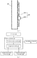
Fig. 5 is a schematic structural diagram of a module of a vehicle hoisting device according to an embodiment of the invention. -
Fig. 6 is a partial schematic structural diagram of a column with an anti-falling mechanism installed in the vehicle hoisting device of the embodiment shown inFigs. 2 and3 . -
Fig. 7 shows the process of an anti-falling action of the anti-falling mechanism shown inFig. 6 , whereinFig. 7(a) shows a state where an anti-falling function is activated but the anti-falling action has not yet been performed; andFig. 7(b) shows a state after the anti-falling action is performed. -
Fig. 8 is a flow chart of a control method for a vehicle hoisting device according to an embodiment of the invention. - The invention will be more completely described with reference to the accompanying drawings. Exemplary embodiments of the invention are shown in the accompanying drawings. However, the invention may be implemented in many different forms and should not be construed as being limited to the embodiments set forth herein. On the contrary, these embodiments are provided to make the disclosure thorough and complete and fully pass on the concept of the invention to those skilled in the art. In the drawings, the same numerals indicate the same elements or components, and thus description of these is omitted.
- In this document, "vehicle" refers to a battery electric vehicle or a hybrid vehicle using a traction battery to at least partially provide drive. A traction battery of a vehicle is installed, for example, at an approximate position of a chassis of the vehicle, thus if a battery swap operation needs to be conveniently performed, a
vehicle hoisting device 20 of an embodiment of the invention needs to be used to lift the vehicle, and of course, thevehicle hoisting device 20 is also able to lower the vehicle. - The
vehicle hoisting device 20 of an embodiment of the invention is used in a battery swap station to construct abattery swap station 10 shown inFig. 1 . Thebattery swap station 10 mainly comprises abattery storage 11, avehicle hoisting device 20, atrack rail 13 provided in thebattery storage 11 and thevehicle hoisting device 20, and abattery swap trolley 15 traveling on thetrack rail 13. When performing a battery swap operation, thevehicle hoisting device 20 needs to lift avehicle 900 to a preset height, under thevehicle 900 thebattery swap trolley 15 removes a traction battery needing to be exchanged from a chassis of the vehicle, then conveys a fully charged traction battery from thebattery storage 11 to an area below thevehicle 900, and after the traction battery is aligned to a traction battery installation position of thevehicle 900, performs automated installation. - The
battery swap station 10 of the embodiment above does not require operating personnel to enter an area around thevehicle 900 in a battery swap process, ensuring battery swap safety, for example, personnel may be prohibited from entering the area where thevehicle hoisting device 20 is located. - In the embodiment of the invention, the main function of the
vehicle hoisting device 20 is lifting thevehicle 900 to a preset position. However, it shall be understood that thevehicle hoisting device 20 is also able to position thevehicle 900 at a position on a horizontal plane in a perpendicular height direction, but specific description of this function is omitted below. - As shown in
Figs. 2 and3 , thevehicle hoisting device 20 of the embodiment of the invention is a column-type hoisting device, using a plurality ofcolumns 23, for example, fourcolumns operation platform 21 is provided in thevehicle hoisting device 20, and the fourcolumns operation platform 21. - According to needs, the
columns columns vehicle hoisting device 20, for example, alifting beam assembly 25a is installed between thecolumn 23a and thecolumn 23d, and alifting beam assembly 25b is installed between thecolumn 23b and thecolumn 23c. Thelifting beam assembly 25a and thelifting beam assembly 25b are arranged substantially parallel to the horizontal, and prior to lifting, a vehicle to be lifted 200 is moved onto the lifting beam assembly 25, and two sides of the vehicle 200 (for example, left and right sides) are respectively placed on thelifting beam assembly 25a and thelifting beam assembly 25b. In the process of lifting or lowering, thelifting beam assembly 25a is able to move up and down in the height direction relative to thecolumns lifting beam assembly 25b is able to move up and down in the height direction relative to thecolumns lifting beam assemblies lifting beam assemblies - In an embodiment, the
lifting beam assemblies support arms 251, thesupport arms 251 of each lifting beam assembly 25 extending inwards, and four wheels of the vehicle 200 are able to be positioned on the foursupport arms 251. Eachsupport arm 251 is correspondingly provided with a motor, thereby enabling position adjustment of the vehicle 200 to be realized on a horizontal plane. - Taking into account the considerable weight of the vehicle 200, in an embodiment of the invention, an
AC motor 28 is selected as a power component. TheAC motor 28 may specifically be a three-phase AC motor, and a corresponding type of theAC motor 28 can be selected and configured according to specific needs. Thecorresponding AC motor 28 is provided with acontrol component 29, and thecontrol component 29 is used for controlling the running of themotor 28, even including a brake action and a brake release action of themotor 28. In this way, theAC motor 28 and thecontrol component 29 principally constitute a motive power system, and they are able to drive the upward and downward movements of thelifting beam assembly 25a and thelifting beam assembly 25b. Thecontrol component 29 can specifically be realized, for example, by means of a PLC, and can be modularized and installed in acorresponding AC motor 28. - Continuing with what is shown in
Figs. 2 and3 , the motive power system can be installed on atop platform 27 supported by thecolumns top platform 27 can comprise cross beams (for example, a beam between thecolumns columns columns columns top platform 27, wherein the top lifting chain 29a is able to transfer motive power output by theAC motor 28 to thelifting beam assembly 25a, thereby driving thelifting beam assembly 25a to move up and down in the height direction along thecolumns AC motor 28 to thelifting beam assembly 25b, thereby driving thelifting beam assembly 25b to move up and down in the height direction along thecolumns - In an embodiment, the
lifting beam assembly 25a and thelifting beam assembly 25b use thesame AC motor 28 for synchronous driving, that is, the top lifting chains 29a and 29b are synchronously driven by thesame AC motor 28. In another alternative embodiment, the top lifting chains 29a and 29b usedifferent AC motors 28 for synchronous driving, for example, two synchronously controlledAC motors 28. - Continuing with what is shown in
Figs. 2 and3 , corresponding track rails can be provided on thecolumns lifting beam assembly 25a and thelifting beam assembly 25b are able to respectively travel along the respective track rail on thecolumns 23. - As shown in
Fig. 2 to Fig. 5 , thevehicle hoisting device 20 further comprises aheight measurement component 24 installed on thecolumns 23. Theheight measurement component 24 comprises a heightmeasurement component measure 24a installed on at least one of thecolumn 23a andcolumn 23d, used for real time measurement of a current first height value of thelifting beam assembly 25a and feeding the value back to a control component 25 (as shown inFig. 6 ); and theheight measurement component 24 further comprises a heightmeasurement component measure 24b installed on at least one of thecolumn 23b andcolumn 23c, used for real time measurement of a current second height value of thelifting beam assembly 25b and feeding the value back to the control component 25 (as shown inFig. 6 ). - In view of the beam-type structure of the
lifting beam assembly 25a, it is entirely synchronously lifted or lowered, such that aheight measurement component 24 provided on one of thecolumn 23a andcolumn 23d can measure the height of thelifting beam assembly 25a, and in the same way, aheight measurement component 24 provided on one of thecolumn 23b andcolumn 23c can measure the height of thelifting beam assembly 25b. Of course, a correspondingheight measurement component 24 can be provided on each column 25 according to needs. - It should be noted that two
height measurement components 24, for example, the heightmeasurement component measure 24a and the heightmeasurement component measure 24b, can be diagonally installed on different columns, for example, respectively installed on thecolumn 23a andcolumn 23c of thecolumns column 23b andcolumn 23d of thecolumns height measurement components 24 can best embody the imbalance of the lifted vehicle 200. - Each
height measurement component 24 can be additionally installed between thecorresponding column 23 and one end of the corresponding lifting beam assembly 25. In an embodiment, as shown inFig. 4 , theheight measurement component 24 is realized by means of an encoder scale, which comprises ascale member 241 installed on thecolumn 23 and anencoder 242 moving up and down together with the lifting beam assembly 25. In the process of lifting or lowering, theencoder 242 can detect an amount of displacement of the lifting beam assembly 25 relative to the fixedscale member 241, i.e. reading a first height value or a second height value, and sends the height value in the form of a feedback signal to acomparison module 291 of thecontrol component 29 as shown inFig. 5 . Thescale member 241 is specifically a linear scale member installed in the height direction. - The
control component 29 of theAC motor 28 is able to control the lifting height of thelifting beam assemblies height measurement components 24. Taking thecontrol component 29 controlling a lifting process as an example, in the lifting process, assuming that the lifting height is controlled based on the heightmeasurement component measure 24a corresponding to thelifting beam assembly 25a, thecontrol component 29 will emit an instruction of the need to lift thelifting beam assemblies AC motor 28, theAC motor 28, based on the instruction, synchronously drives thelifting beam assemblies measurement component measure 24a feeds back the measured current first height value, thecomparison module 291 of thecontrol component 29 can compare the first height value and the preset height corresponding to the instruction, and if there is a deviation between the two, thecontrol component 29 can control an execution component (for example, the AC motor 28) to move in the direction of eliminating the deviation until the deviation is substantially equal to zero or the deviation is substantially eliminated. Therefore, relative precision control of the lifting height of thevehicle 900 can be achieved. In particular, when theheight measurement component 24 is the encoder scale, the height value fed back is more accurate so the accuracy of the lifting height is better. - It shall be understood that in other embodiments, the lifting height can be controlled based on the height
measurement component measure 24b corresponding to thelifting beam assembly 25b. - It should be noted that although the height values measured by the height
measurement component measure 24a or the heightmeasurement component measure 24b are fed back to thecontrol component 29 to control the lifting height, since problems exist such as deviation in operating mechanisms and inaccuracy in synchronous transfer, these may lead to the current height of thelifting beam assembly 25a and thelifting beam assembly 25b being inconsistent in the process of lifting or lowering, so the problem of imbalance of the vehicle 200 may exist. - To detect imbalance of the vehicle 200 in the process of lifting or lowering, and prevent the vehicle 200 from tilting excessively, the second height value measured by the height
measurement component measure 24b of theheight measurement component 24 can serve as a height feedback signal of the first height value measured by the heightmeasurement component measure 24a, that is to say, the second height value corresponding to thelifting beam assembly 25b serves as the feedback signal of the first height value corresponding to thelifting beam assembly 25a. In another embodiment, the first height value measured by the heightmeasurement component measure 24a of theheight measurement component 24 can serve as a height feedback signal of the second height value measured by the heightmeasurement component measure 24b, that is to say, the first height value corresponding to thelifting beam assembly 25a serves as the feedback signal of the second height value corresponding to thelifting beam assembly 25b. The measurement of the heightmeasurement component measure 24a and the measurement of the heightmeasurement component measure 24b can mutually serve as a feedback detection component of the other party. - Continuing with what is shown in
Fig. 5 , the first height value and the second height value of the measurement of the heightmeasurement component measure 24a and the measurement of the heightmeasurement component measure 24b at the same moment are fed back to thecomparison module 291 of thecontrol component 29, and thecomparison module 291 is used for comparing the first height value and the second height value to determine a difference value therebetween. Furthermore, atilt determination module 292 is also provided in thecontrol component 29, and thetilt determination module 292 is used for determining that the vehicle 200 has tilted in the process of lifting or lowering when the difference value is greater than or equal to a tolerance value. The tolerance value can be preset, for example, manually set by means of a person, the tolerance value reflects the balance requirements of the vehicle 200 in the process of lifting or lowering, and the specific size of the tolerance value is not restrictive. In this way, thecontrol component 29 can monitor in real time whether the vehicle 200 is tilting in the process of lifting or lowering, aiding in timely averting danger in the battery swap process. - In an embodiment, the
control component 29 is further configured to send an instruction, when determining that tilting has occurred, to trigger theAC motor 28 to perform a brake action. As an example, when thetilt determination module 292 determines that tilting has occurred, thecontrol component 29 sends a brake instruction, and theAC motor 28 accordingly and timely performs a brake action, pausing or stopping the output of motive power. - Continuing with what is shown in
Figs. 5 and6 , in an embodiment, thevehicle hoisting device 20 is further provided with ananti-falling mechanism 26 located between thecolumn 23 and one end of the corresponding lifting beam assembly 25, and theanti-falling mechanism 26 can be controlled to execute an anti-falling action to prevent the vehicle 200 being lifted from falling, effectively improving safety. - In an embodiment, the
control component 29 is further configured to send an instruction, when determining that tilting has occurred, to trigger theanti-falling mechanism 26 to perform an anti-falling action. As an example, when thetilt determination module 292 determines that tilting has occurred, thecontrol component 29 sends an anti-falling instruction, and theanti-falling mechanism 26 accordingly and timely performs an anti-falling action, pausing or stopping the lifting/lowering process. - It shall be understood that when determining that tilting has occurred, the
control component 29 can simultaneously send the above-mentioned brake instruction and anti-falling instruction, and the brake action and the anti-falling action are performed simultaneously, effectively guaranteeing safety. - In an embodiment, as shown in
Figs. 6 and7 , theanti-falling mechanism 26 comprises apedestal 261, wherein thepedestal 261 can be fixedly installed at one end of the lifting beam assembly 25, and can move up and down along with the lifting beam assembly 25. When the lifting beam assembly 25 is lifted, atop lifting chains 29 act with asuspension chain 262, and thepedestal 261 is driven to move up and down along thecolumns 23 by means of thesuspension chain 262. - Specifically, the
anti-falling mechanism 26 further comprises aratchet 231 provided on thecolumns 23 and facing thepedestal 261. Apawl 263, corresponding to theratchet 231, is provided, thepawl 263 is installed on thepedestal 261 via ashaft 264, and thepawl 263 can rotate around theshaft 264. In a normal state, thesuspension chain 262 is connected to an upper end of thepawl 263, making thepawl 263 in a pulled state, i.e. the initial state shown inFig. 7(a) . At this point, a lower end of thepawl 263 is separated from theratchet 231, and does not affect the upward and downward movements of thepedestal 261, while a back face of the lower end of thepawl 263 is correspondingly provided with anelastic component 266, which, in the initial state shown inFig. 7(a) , is pressed onto thepedestal 261 by thepawl 263. - If a transmission chain breaks in the lifting or lowering process, for example, the
suspension chain 262 breaks, as shown inFig. 7(b) , thepawl 263 disengages from thesuspension chain 262 and is in a free state relative to thesuspension chain 262, that is, not pulled by thesuspension chain 262. In this way, the lower end of thepawl 263 rotates around theshaft 264 in the direction shown inFig. 7(b) under the elastic force of theelastic component 266, and thepawl 263 catches theratchet 231, thereby blocking thepedestal 261 and the lifting beam assembly 25 fixedly connected thereto from falling downwards, and preventing a falling accident occurring with the vehicle 200. - In an embodiment, as shown in
Figs. 6 and7 , the correspondingratchet 231 can further be provided with apawl 269, thepawl 269 being installed on thepedestal 261 via ashaft 268, and thepawl 269 can rotate around theshaft 268. A face corresponding to a lower end of thepawl 269 and opposite the ratchet 231 (i.e. a back face) is provided with anelectromagnetic actuating component 267, wherein theelectromagnetic actuating component 267 can be fixedly installed on thepedestal 261, with an output shaft thereof abutting against the back face of the lower end of thepawl 269. In a normal state, as shown inFig. 7(a) , the output shaft of theelectromagnetic actuating component 267 retracts, the lower end of thepawl 269 is separated from theratchet 231 and does not affect the upward and downward movements of thepedestal 261. - The
electromagnetic actuating component 267 can be coupled with thecontrol component 29 as shown inFigs. 2 and5 , and receive the anti-falling instruction from thecontrol component 29. When the anti-falling instruction is received, theelectromagnetic actuating component 267 drives the output shaft to extend, as shown inFig. 7(b) , pushing the lower end of thepawl 269 to rotate towards theratchet 231, and thepawl 269 catches theratchet 231, thereby blocking thepedestal 261 and the lifting beam assembly 25 fixedly connected thereto from moving relative to thecolumns 23, and while blocking the vehicle 200 from continuing to be lifted or lowered, preventing a falling accident occurring with the vehicle 200 due to tilting. - It shall be understood that the
electromagnetic actuating component 267 can also receive an anti-falling instruction from other components, and an anti-falling action similar to the above is executed by means of theelectromagnetic actuating component 267 and thepawl 269. - As an example, for safety protection in a battery swap process, personnel are prohibited from entering a battery swap zone in an automated battery swap process. Therefore, a protection grating (not shown in the figures) is provided around the vehicle hoisting device 20 (for example, on the
columns 23 or next to them). If personnel enter the battery swap zone, firstly the protection grating detects the entry, the protection grating is triggered to send an anti-falling instruction to theelectromagnetic actuating component 267, and thepedestal 261 and the lifting beam assembly 25 fixedly connected thereto can be locked by means of theelectromagnetic actuating component 267 and thepawl 269, preventing the personnel entering and a safety incident occurring. - Therefore, the
vehicle hoisting device 20 is further improved in terms of the safety of the battery swap process. - A control method for the
vehicle hoisting device 20 according to the above embodiments of the invention is described below also in view ofFig. 8 , taking the battery swap operation process as an example. - Firstly, in step S81, the motive power system, such as the
AC motor 28, is powered on. - Next, in step S82, a battery swap station system (comprising the vehicle hoisting device) performs self-testing and is readied.
- Next, in step S83, setting parameters, such as the tolerance value, is performed.
- Next, in step S84, lifting is started. At this point, it indicates that the lifting action is already readied.
- Next, in step S851, the braking of the
motor 28 of the motive power system is released. Corresponding to this step, step S852, step S853 and step S854 can be selected according to needs to activate a corresponding safety function. As an example, in step S852, height detection and feedback is activated, theheight measurement component 24 is readied; as another example, in step S853, an anti-falling function is activated, and the anti-falling mechanism 26 (for example, the electromagnetic actuating component 267) is readied; and as yet another example, in step S854, safety protection is activated, and the protection grating is readied. - Next, in step S85, under the control of the
control module 29, theAC motor 28 outputs motive power to perform the lifting action. In the lifting process, the lifting height can be controlled by means of any one of theheight measurement components 24, thereby controlling the lifting precision or accuracy. - In an embodiment, in this step, since the height detection and feedback is activated, the
height measurement components control component 29. - In an embodiment, in this step, since safety protection is activated, the protection grating also detects in real time and feeds back corresponding data or instruction.
- Next, in step S87, the first height value fed back by the
height measurement component 24a is compared with the second height value fed back by theheight measurement component 24b to determine a difference value therebetween, and judge whether the difference value is greater than or equal to a tolerance value. - If "no", this indicates that the
lifting beam assembly 25a and thelifting beam assembly 25b are indeed synchronously lifting, and the vehicle 200 is not tilting, and the lifting action is maintained until step S92, where the lifting height is reached. - If "yes", this indicates that the
lifting beam assembly 25a and thelifting beam assembly 25b are currently not synchronously lifting, and the vehicle 200 is tilting. On the one hand, a brake instruction can be sent by thecontrol component 29 for theAC motor 28 to perform a brake action, i.e. step S89, and on the other hand, thecontrol component 29 can send an anti-falling instruction to perform an anti-falling action, i.e. step S90, for example, theelectromagnetic actuating component 267 drives the output shaft to extend, as shown inFig. 7(b) , pushing the lower end of thepawl 269 to rotate towards theratchet 231, and thepawl 269 catches theratchet 231, thereby blocking thepedestal 261 and the lifting beam assembly 25 fixedly connected thereto from moving relative to thecolumns 23, and preventing the vehicle 200 from continuing to be lifted. - In an embodiment, step S88 is also executed at the same time as executing step S87, judging whether the protection grating is in operation.
- If "no", this indicates that in the process of the lifting action, no person has entered the battery swap zone, the lifting action can be maintained until step S92, where the lifting height is reached.
- If "yes", the protection grating can send an anti-falling instruction to perform an anti-falling action, i.e. step S90, for example, the
electromagnetic actuating component 267 drives the output shaft to extend, as shown inFig. 7(b) , pushing the lower end of thepawl 269 to rotate towards theratchet 231, and thepawl 269 catches theratchet 231, thereby blocking thepedestal 261 and the lifting beam assembly 25 fixedly connected thereto from moving relative to thecolumns 23, and preventing the vehicle 200 from continuing to be lifted. - In an embodiment, if step S87 and step S88 are judged to be "yes", an alarm can be given in both cases, i.e. step S91, thereby facilitating operating personnel in timely acquiring and responding to the alarm to perform a corresponding operation or action.
- After step S92, braking of the
AC motor 28 can be performed, i.e. step S93, and an anti-falling action is performed, i.e. step S94. In this way, the vehicle 200 is safely lifted to a corresponding height, an associated action is executed and lifting is completed, i.e. step S95. At this point, a traction battery swap operation can be performed by means of abattery swap trolley 15. - After the traction battery swap operation has been completed, for example, it proceeds to step S96, i.e. a step for starting to lower. It should be noted that the lowering process and the lifting process are reverse processes; however, the same or a similar method to the lifting process can be used, thereby guaranteeing safety of the lowering process, for example, similarly executing steps S87 to S95, which will not be repeated here.
- It should be noted that some block diagrams shown in
Fig. 5 are functional entities and do not necessarily correspond to physical or logical independent entities. These functional entities may be implemented as software, one or more hardware modules or integrated circuits, or different networks and/or processor apparatuses and/or microcontroller apparatuses. - In the solutions of the embodiments of the invention, by means of providing a first height measurement component and a second height measurement component installed on different columns corresponding to different lifting beam assemblies, wherein the height value measured by one height measurement component is able to serve as a feedback value for the height value measured by the other height measurement component, whether the heights of different lifting beam assemblies are consistent can be accurately determined in an automated manner, thereby accurately determining whether the vehicle is tilting, which aids in timely avoiding continuing to lift or lower the vehicle when the vehicle is tilting, which causes safety problems, and thus the vehicle lifting or lowering process is safer.
- The examples above principally describe the vehicle hoisting device and the control method thereof, and the battery swap station using the vehicle hoisting device in the invention. Although only some embodiments of the invention are described, it will be appreciated by those skilled in the art that the invention may be embodied in many other forms without departing from the essence and scope thereof. Therefore, the presented examples and implementation manners are regarded to be schematic rather than limitative, and without departing from the spirit and scope of the invention that are defined by the appended claims, the invention may cover various changes and replacements.
Claims (15)
- A vehicle hoisting device for a battery swap station, the vehicle hoisting device comprising:a first set of columns and a second set of columns,a first lifting beam assembly installed between the first set of columns and able to move up and down relative to the first set of columns in a height direction,a second lifting beam assembly installed between the second set of columns and able to move up and down relative to the second set of columns in the height direction, andan AC motor for driving the upward and downward movements of the first lifting beam assembly and the second lifting beam assembly, and a control component for the AC motor,wherein two sides of a vehicle being lifted are respectively placed on the first lifting beam assembly and the second lifting beam assembly;
characterized by further comprising:a first height measurement component installed on at least one column of the first set of columns, and used for measuring a current first height value of the first lifting beam assembly in real time and feeding the value back to the control component; anda second height measurement component installed on at least one column of the second set of columns, and used for measuring a current second height value of the second lifting beam assembly in real time and feeding the value back to the control component. - The vehicle hoisting device according to claim 1, characterized in that the control component comprises:a comparison module for comparing the first height value fed back by the first height measurement component and the second height value fed back by the second height measurement component to determine a difference value therebetween; anda tilt determination module for determining that the vehicle has tilted in the process of lifting or lowering when the difference value is greater than or equal to a tolerance value.
- The vehicle hoisting device according to claim 1 or 2, characterized in that the control component is further configured to send an instruction, when determining that tilting has occurred, to trigger the AC motor to brake and/or trigger an anti-falling mechanism to perform an anti-falling action.
- The vehicle hoisting device according to claim 3, characterized in that a ratchet corresponding to the anti-falling mechanism is provided on the columns; and the anti-falling mechanism comprises:a pedestal able to move up and down relative to the columns in the height direction;a first pawl installed on the pedestal via a first shaft and able to rotate relative to the first shaft; andan electromagnetic actuating component fixedly installed on the pedestal, with an output shaft thereof abutting against a face of the first pawl facing away from the ratchet.
- The vehicle hoisting device according to claim 4, characterized in that the electromagnetic actuating component drives the output shaft thereof to extend when an anti-falling instruction is received, thereby pushing a lower end of the first pawl to rotate towards the ratchet until the first pawl catches the ratchet.
- The vehicle hoisting device according to claim 1, characterized by further comprising an anti-falling mechanism provided in front of the columns and the corresponding first lifting beam assembly or second lifting beam assembly, wherein a ratchet corresponding to the anti-falling mechanism is provided on the columns; and the anti-falling mechanism comprises:a pedestal able to move up and down relative to the columns in the height direction;a second pawl installed on the pedestal via a second shaft and able to rotate relative to the second shaft, with an upper end of the second pawl being pulled by a suspension chain in a normal state; andan elastic component installed on the pedestal and, in the normal state, able to output a resilient force to a face of a lower end of the second pawl facing away from the ratchet.
- The vehicle hoisting device according to claim 6, characterized in that in an abnormal state where the suspension chain breaks, the resilient force of the elastic component pushes the lower end of the second pawl to rotate towards the ratchet until the second pawl catches the ratchet.
- The vehicle hoisting device according to claim 1, characterized in that either of the first height measurement component and the second height measurement component is used to control a lifting or lowering height of the first lifting beam assembly and the second lifting beam assembly.
- The vehicle hoisting device according to claim 1, characterized by further comprising a protection grating for detecting whether a person has entered the vehicle hoisting device.
- The vehicle hoisting device according to claim 1, characterized in that the first height measurement component and the second height measurement component are encoder scales.
- A battery swap station, characterized by comprising a vehicle hoisting device according to any one of claims 1 to 10.
- A control method for a vehicle hoisting device according to claim 1, characterized by comprising steps of:comparing the first height value fed back by the first height measurement component and the second height value fed back by the second height measurement component to determine a difference value therebetween; anddetermining that the vehicle has tilted in the process of lifting or lowering when the difference value is greater than or equal to a tolerance value.
- The control method according to claim 12, characterized by further comprising a step of:
when determining that tilting has occurred, triggering the AC motor to brake and/or triggering an anti-falling mechanism to perform an anti-falling action. - The control method according to claim 12, characterized by further comprising a step of:
when determining that a person has entered the vehicle hoisting device, triggering an anti-falling mechanism to perform an anti-falling action. - The control method according to claim 12, characterized by further comprising a parameter setting step for setting the tolerance value.
Applications Claiming Priority (2)
| Application Number | Priority Date | Filing Date | Title |
|---|---|---|---|
| CN201711072730.2A CN109502504A (en) | 2017-11-03 | 2017-11-03 | Vehicle lifting device for power station and control method thereof |
| PCT/CN2018/075145 WO2019085317A1 (en) | 2017-11-03 | 2018-02-02 | Vehicle lifting device for battery swapping station, and control method therefor |
Publications (2)
| Publication Number | Publication Date |
|---|---|
| EP3705448A1 true EP3705448A1 (en) | 2020-09-09 |
| EP3705448A4 EP3705448A4 (en) | 2021-09-01 |
Family
ID=65745383
Family Applications (1)
| Application Number | Title | Priority Date | Filing Date |
|---|---|---|---|
| EP18872077.5A Pending EP3705448A4 (en) | 2017-11-03 | 2018-02-02 | Vehicle lifting device for battery swapping station, and control method therefor |
Country Status (3)
| Country | Link |
|---|---|
| EP (1) | EP3705448A4 (en) |
| CN (1) | CN109502504A (en) |
| WO (1) | WO2019085317A1 (en) |
Cited By (1)
| Publication number | Priority date | Publication date | Assignee | Title |
|---|---|---|---|---|
| EP3708445A4 (en) * | 2017-11-08 | 2021-08-18 | NIO (Anhui) Holding Co., Ltd. | Battery-changing transportation apparatus and positioning control method therefor |
Families Citing this family (6)
| Publication number | Priority date | Publication date | Assignee | Title |
|---|---|---|---|---|
| CN113895282A (en) * | 2020-06-22 | 2022-01-07 | 奥动新能源汽车科技有限公司 | Battery replacement equipment anti-falling device, battery replacement equipment and battery replacement equipment anti-falling method |
| CN119239391A (en) * | 2020-06-22 | 2025-01-03 | 奥动新能源汽车科技有限公司 | Battery swap equipment anti-fall device, battery swap equipment, and battery swap equipment anti-fall method |
| CN113895284A (en) * | 2020-06-22 | 2022-01-07 | 奥动新能源汽车科技有限公司 | Battery replacement equipment, battery replacement station and battery replacement equipment control method |
| WO2022064230A1 (en) | 2020-09-24 | 2022-03-31 | Bakogiannis Nikolaos | System and method for electrical vehicles battery swapping |
| CN114763075B (en) * | 2020-12-31 | 2024-12-06 | 奥动新能源汽车科技有限公司 | Fall prevention devices, battery transfer systems, battery swap stations or energy storage stations |
| CN115367668B (en) * | 2022-10-24 | 2023-01-31 | 苏州艾沃意特汽车设备有限公司 | Lifting system for vehicle |
Family Cites Families (15)
| Publication number | Priority date | Publication date | Assignee | Title |
|---|---|---|---|---|
| NL9200688A (en) * | 1992-04-14 | 1993-11-01 | Stertil Bv | SAFETY ROD DEVICE. |
| US6186280B1 (en) * | 1999-09-14 | 2001-02-13 | Snap-On Technologies, Inc. | Lift safety system |
| WO2002034665A2 (en) * | 2000-10-27 | 2002-05-02 | Delaware Capital Formation, Inc. | Electronically controlled vehicle lift and vehicle service system |
| JP5299882B2 (en) * | 2007-03-30 | 2013-09-25 | 安全自動車株式会社 | Vehicle lift device |
| NL2011131C2 (en) * | 2013-07-10 | 2015-01-13 | Stertil Bv | Lifting system for lifting a vehicle comprising one or more lifting devices and a release system, and method there for. |
| CN104743470A (en) * | 2015-03-31 | 2015-07-01 | 苏州艾沃意特机械设备制造有限公司 | Visualized self-leveling double-column type lifter |
| CN204984365U (en) * | 2015-07-28 | 2016-01-20 | 杨广柱 | Can monitor equipment of oil rig substructure jacking height |
| CN206069282U (en) * | 2016-07-07 | 2017-04-05 | 蔚来汽车有限公司 | Battery lifts for small automated battery swap stations |
| CN205773105U (en) * | 2016-07-14 | 2016-12-07 | 无锡职业技术学院 | A kind of falling prevention control device of shearing type lifter |
| CN106185703A (en) * | 2016-07-18 | 2016-12-07 | 合肥航航空设备有限公司 | A kind of four post lifting machines improving parking stability |
| CN107161904A (en) * | 2017-04-28 | 2017-09-15 | 赛埃孚汽车保修设备(太仓)有限公司 | A kind of twin columns elevator and its method of work with grabbing device |
| CN107200287B (en) * | 2017-06-15 | 2019-04-30 | 安徽佳航智能设备有限公司 | A kind of packaged type lifting machine and its lifting mechanism control system |
| CN107055391A (en) * | 2017-06-15 | 2017-08-18 | 合肥佳航机电设备有限公司 | One kind is based on hydraulic cylinder self set-up type lifting machine and its assembly method |
| CN107244638A (en) * | 2017-06-15 | 2017-10-13 | 合肥航机械科技股份有限公司 | A kind of control system for the post lifting machine of hydraulic pressure four |
| CN207811165U (en) * | 2017-11-03 | 2018-09-04 | 蔚来汽车有限公司 | Vehicle lifting device for power changing station and power changing station using same |
-
2017
- 2017-11-03 CN CN201711072730.2A patent/CN109502504A/en active Pending
-
2018
- 2018-02-02 EP EP18872077.5A patent/EP3705448A4/en active Pending
- 2018-02-02 WO PCT/CN2018/075145 patent/WO2019085317A1/en not_active Ceased
Cited By (1)
| Publication number | Priority date | Publication date | Assignee | Title |
|---|---|---|---|---|
| EP3708445A4 (en) * | 2017-11-08 | 2021-08-18 | NIO (Anhui) Holding Co., Ltd. | Battery-changing transportation apparatus and positioning control method therefor |
Also Published As
| Publication number | Publication date |
|---|---|
| WO2019085317A1 (en) | 2019-05-09 |
| EP3705448A4 (en) | 2021-09-01 |
| CN109502504A (en) | 2019-03-22 |
Similar Documents
| Publication | Publication Date | Title |
|---|---|---|
| WO2019085317A1 (en) | Vehicle lifting device for battery swapping station, and control method therefor | |
| CN108490367B (en) | Automatic detection system and method for power battery and battery safety judgment and disposal method | |
| CN207811165U (en) | Vehicle lifting device for power changing station and power changing station using same | |
| US9290369B2 (en) | Lifting column for lifting a load, lifting system provided therewith and method for measuring a load | |
| JP2023511579A (en) | Shuttle and shuttle control method | |
| CN113525456B (en) | Control method and device of magnetic levitation train, and control platform | |
| CN211710848U (en) | Operation and maintenance system for rail transit rolling stock | |
| CN110143163B (en) | AGV trolley and automatic conveying method thereof | |
| CN103979377B (en) | Real-time monitoring system based on Quick Response Code car elevator and method for supervising thereof | |
| EP3725608A1 (en) | Battery replacement fault diagnostic method and system | |
| KR20200098555A (en) | Battery replacement cart, battery replacement control system and control method thereof | |
| CN102829981A (en) | Detection platform for strength of protective device at rear lower part of automobile/trailer and detecting method thereof | |
| KR102940383B1 (en) | 4-way shuttle car body and pallet obstacle avoidance inspection device and method of operation thereof | |
| CN103193129B (en) | Control device of elevator | |
| US12129156B2 (en) | Apparatus and method of voltage detection of vehicles on a vehicle lift system | |
| CN113733968A (en) | Electric vehicle battery replacing system, battery replacing station and battery replacing method | |
| CN208166263U (en) | Elevator brake device for detecting performance | |
| KR101675428B1 (en) | Battery exchanging station system for electric vehicle | |
| CN210347817U (en) | Mobile carrying platform for live detection of substation equipment | |
| CN104764483A (en) | Temperature and humidity vibration test device | |
| CN202743215U (en) | Full-automatic electric vehicle battery replacement station | |
| CN204064624U (en) | A kind of elevator brake device for detecting performance | |
| JP6041601B2 (en) | Aerial work platform | |
| CN116674420B (en) | Method, device and system for controlling power exchange station and power exchange station | |
| CN102126614A (en) | Automobile body positioning system and positioning method thereof |
Legal Events
| Date | Code | Title | Description |
|---|---|---|---|
| STAA | Information on the status of an ep patent application or granted ep patent |
Free format text: STATUS: THE INTERNATIONAL PUBLICATION HAS BEEN MADE |
|
| PUAI | Public reference made under article 153(3) epc to a published international application that has entered the european phase |
Free format text: ORIGINAL CODE: 0009012 |
|
| STAA | Information on the status of an ep patent application or granted ep patent |
Free format text: STATUS: REQUEST FOR EXAMINATION WAS MADE |
|
| 17P | Request for examination filed |
Effective date: 20200603 |
|
| AK | Designated contracting states |
Kind code of ref document: A1 Designated state(s): AL AT BE BG CH CY CZ DE DK EE ES FI FR GB GR HR HU IE IS IT LI LT LU LV MC MK MT NL NO PL PT RO RS SE SI SK SM TR |
|
| AX | Request for extension of the european patent |
Extension state: BA ME |
|
| RAP1 | Party data changed (applicant data changed or rights of an application transferred) |
Owner name: NIO (ANHUI) HOLDING CO., LTD. |
|
| RIN1 | Information on inventor provided before grant (corrected) |
Inventor name: DING, XIKUN Inventor name: LI, NAN Inventor name: MA, YONGYUE Inventor name: BENGTSSON, JAN Inventor name: TIAN, XIAOTAO |
|
| DAV | Request for validation of the european patent (deleted) | ||
| DAX | Request for extension of the european patent (deleted) | ||
| A4 | Supplementary search report drawn up and despatched |
Effective date: 20210804 |
|
| RIC1 | Information provided on ipc code assigned before grant |
Ipc: B66F 7/02 20060101AFI20210729BHEP Ipc: B66F 7/20 20060101ALI20210729BHEP Ipc: B66F 7/28 20060101ALI20210729BHEP |
|
| STAA | Information on the status of an ep patent application or granted ep patent |
Free format text: STATUS: EXAMINATION IS IN PROGRESS |
|
| 17Q | First examination report despatched |
Effective date: 20230517 |