EP3705389A1 - Saddled vehicle - Google Patents
Saddled vehicle Download PDFInfo
- Publication number
- EP3705389A1 EP3705389A1 EP18903737.7A EP18903737A EP3705389A1 EP 3705389 A1 EP3705389 A1 EP 3705389A1 EP 18903737 A EP18903737 A EP 18903737A EP 3705389 A1 EP3705389 A1 EP 3705389A1
- Authority
- EP
- European Patent Office
- Prior art keywords
- braking force
- wheel
- brake
- headlight
- adjusting device
- Prior art date
- Legal status (The legal status is an assumption and is not a legal conclusion. Google has not performed a legal analysis and makes no representation as to the accuracy of the status listed.)
- Withdrawn
Links
Images





Classifications
-
- B—PERFORMING OPERATIONS; TRANSPORTING
- B62—LAND VEHICLES FOR TRAVELLING OTHERWISE THAN ON RAILS
- B62L—BRAKES SPECIALLY ADAPTED FOR CYCLES
- B62L3/00—Brake-actuating mechanisms; Arrangements thereof
- B62L3/08—Mechanisms specially adapted for braking more than one wheel
-
- B—PERFORMING OPERATIONS; TRANSPORTING
- B62—LAND VEHICLES FOR TRAVELLING OTHERWISE THAN ON RAILS
- B62K—CYCLES; CYCLE FRAMES; CYCLE STEERING DEVICES; RIDER-OPERATED TERMINAL CONTROLS SPECIALLY ADAPTED FOR CYCLES; CYCLE AXLE SUSPENSIONS; CYCLE SIDECARS, FORECARS, OR THE LIKE
- B62K19/00—Cycle frames
- B62K19/30—Frame parts shaped to receive other cycle parts or accessories
- B62K19/38—Frame parts shaped to receive other cycle parts or accessories for attaching brake members
-
- B—PERFORMING OPERATIONS; TRANSPORTING
- B62—LAND VEHICLES FOR TRAVELLING OTHERWISE THAN ON RAILS
- B62L—BRAKES SPECIALLY ADAPTED FOR CYCLES
- B62L3/00—Brake-actuating mechanisms; Arrangements thereof
- B62L3/02—Brake-actuating mechanisms; Arrangements thereof for control by a hand lever
- B62L3/023—Brake-actuating mechanisms; Arrangements thereof for control by a hand lever acting on fluid pressure systems
-
- B—PERFORMING OPERATIONS; TRANSPORTING
- B62—LAND VEHICLES FOR TRAVELLING OTHERWISE THAN ON RAILS
- B62L—BRAKES SPECIALLY ADAPTED FOR CYCLES
- B62L5/00—Brakes, or actuating mechanisms therefor, controlled by back-pedalling
- B62L5/20—Brakes, or actuating mechanisms therefor, controlled by back-pedalling the brakes having adjustable braking power
Definitions
- the saddled vehicle 1 is a vehicle on which a rider rides while straddling on a seat 10.
- the saddled vehicle 1 is a motorcycle including a low floor 11.
- the saddled vehicle 1 includes a front wheel 2 in the front of an under-bone type vehicle body frame 12.
- a rear wheel 3, which is a driving wheel, is axially supported by a unit swing engine 13 disposed in a vehicle rear part.
- the arm section 31 extends backward from a left rear part of a crank case 34 of the engine 30 and is located on the left side of the rear wheel 3.
- the rear wheel 3 is axially supported by a rear wheel axle 31a at the rear end portion of the arm section 31 and is cantilevered by the arm section 31.
- a sliding section 97d extending upward is coupled to the shaft member 97c of the front end portion 111b.
- a spring 112 is disposed above the sliding section 97d. The spring 112 urges the front end portion 111b of the arm 111 downward via the sliding section 97d.
- a restricting section 101a recessed downward is formed in the equalizer box 101 above the rear end portion 111c of the arm 111. The rear end portion 111c of the arm 111 is capable of coming into contact with the restricting section 101a.
- the stay 80 includes a pair of left and right fixing bars 81 and an upper cross bar 82, a lower cross bar 83, and a cross plate 84 supported between the left and right fixing bars 81.
- the right brake cable 95 As shown in FIG. 7 , the right brake cable 95, one end of which is connected to the right brake lever 93, is held by a U-shaped cable guide 15d provided on the right side of the handlebar 15 and a U-shaped cable guide 82a provided in the stay 80.
- the right brake cable 95 is routed toward a space between the head pipe 17 and the CBS module 100.
- the right brake cable 95 passes between the head pipe 17 and the CBS module 100. Then, the right brake cable 95 is drawn around to be rear in the front fork 14 on the left side, held by an annular cable guide 73b provided in the left section of the bottom bridge 73, and routed toward the rear left section of the front fender 51.
- the left brake cable 96 As shown in FIG. 7 , the left brake cable 96, one end of which is connected to the left brake lever 94, is held by a U-shaped cable guide 15e provided on the left side of the handlebar 15. The other end of the left brake cable 96 is connected to the input connecting section 103 of the CBS module 100.
- the input connecting section 103 is located substantially symmetrically with respect to the position of the cable guide 82a on the right side.
- the left brake cable 96 and the front interlocking brake cable 97 are held by and connected to the cable guides 15d, 82a, 73b, and 51a provided in the steering system 9 and the CBS module 100 supported by the steering system 9.
- the left brake cable 96 and the front interlocking brake cable 97 are capable of rotating integrally with the steering system 9. The influence of steering is reduced.
- the meter device 43 is disposed behind and above the headlight 41 and above the CBS module 100.
- the periphery of an upper part of the meter device 43 is covered with the meter cover 45.
Landscapes
- Engineering & Computer Science (AREA)
- Mechanical Engineering (AREA)
- Physics & Mathematics (AREA)
- Fluid Mechanics (AREA)
- Motorcycle And Bicycle Frame (AREA)
Abstract
Description
- The present invention relates to a saddled vehicle.
- Japanese Patent Application Laid-Open No.
2016-182838 - In the technique described in Patent Literature 1, since the front of the braking force adjusting device is exposed, the braking force adjusting device is seen from the outside. The brake hose extends from the rear of the head pipe to a steering system operated by the handlebar.
- The present invention has been devised in view of the circumstances, and an object of the present invention is to provide a saddled vehicle with improved external appearance through a reduction of exposure of a braking force adjusting device and improved operability of a handlebar.
- This specification includes all the contents of Indian Patent Application No.
201811004281 filed on February 5, 2018 - The present invention provides a saddled vehicle including: a head pipe (17); bridges (72, 73) pivotally supported by the head pipe (17) to hold front forks (14); a headlight (41) connected to the bridges (72, 73) via a stay (80); a headlight cover (44) that covers a rear of the headlight (41); and a braking force adjusting device (100) that adjusts a braking force applied to a wheel (2) rotatably supported by the front forks (14). The braking force adjusting device (100) is connected to the stay (80) .
- In the invention, the braking force adjusting device (100) may include: a front-wheel-side braking force output terminal (104) that applies a braking force to a front wheel (2); and a rear-wheel-side braking force output terminal (105) that applies a braking force to a rear wheel (3). The rear-wheel-side braking force output terminal (105) may be disposed in a position closer to the head pipe (17) than the front-wheel-side braking force output terminal (104).
- In the invention, a hose (98) extending from the rear-wheel-side braking force output terminal (105) to a rear wheel (3) may be routed to one side in a vehicle width direction of a main frame (18) extending backward from the head pipe (17). The braking force adjusting device (100) may be set on one side in the vehicle width direction with respect to the stay (80).
- In the invention, the braking force adjusting device (100) may be disposed near an upper part of the head pipe (17) .
- In the invention, the saddled vehicle may include a meter device (43) behind and above the headlight (41) and above the braking force adjusting device (100).
- In the invention, the braking force adjusting device (100) may be disposed between a pair of the front forks (14) .
- With the saddled vehicle of the present invention, in the saddled vehicle including a head pipe, bridges pivotally supported by the head pipe to hold front forks, a headlight connected to the bridges via a stay, a headlight cover that covers a rear of the headlight, and a braking force adjusting device that adjusts a braking force applied to a wheel rotatably supported by the front forks, the braking force adjusting device being connected to the stay. With this configuration, since the braking force adjusting device is covered with the headlight cover behind the headlight. Therefore, it is possible to prevent exposure of the braking force adjusting device without separately providing a cover for protection. By providing the braking force adjusting device on a movable side (in a steering system), it is possible to reduce the influence of steering on the hose connected to the handlebar and the front wheel.
- In the invention, the braking force adjusting device may include: a front-wheel-side braking force output terminal that applies a braking force to a front wheel; and a rear-wheel-side braking force output terminal that applies a braking force to a rear wheel. The rear-wheel-side braking force output terminal may be disposed in a position closer to the head pipe than the front-wheel-side braking force output terminal. With this configuration, by disposing the rear-wheel-side braking force output terminal in a position close to the rotation center, it is possible to reduce the influence of steering.
- In the invention, a hose extending from the rear-wheel-side braking force output terminal to the rear wheel may be routed to one side in a vehicle width direction of a main frame extending backward from the head pipe. The braking force adjusting device may be set on one side in the vehicle width direction with respect to the stay. With this configuration, laying of the hose from the braking force adjusting device to the main frame is improved.
- In the invention, the braking force adjusting device may be disposed near an upper part of the head pipe. With this configuration, it is possible to secure a large curvature radius of bending of a rear hose guided to extend along a frame.
- In the invention, the saddled vehicle may include a meter device behind and above the headlight and above the braking force adjusting device. With this configuration, it is possible to protect the braking force adjusting device from above.
- In the invention, the braking force adjusting device may be disposed between a pair of the front forks. With this configuration, it is possible to achieve improvement of antitheft properties concerning the braking force adjusting device.
-
-
FIG. 1 is a left side view of a saddled vehicle according to an embodiment of the present invention; -
FIG. 2 is a left side view of a main part of the saddled vehicle; -
FIG. 3 is a front view of the main part of the saddled vehicle; -
FIG. 4 is a partial sectional view of a CBS module; -
FIG. 5 is an explanatory diagram of the CBS module and a stay in a steering system and is a view of the CBS module and the stay viewed from a front side orthogonal to a front fork; -
FIG. 6 is an explanatory diagram of the CBS module and the stay in the steering system and is a view of the CBS module and the stay viewed further from the left side than a front fork on the left side; -
FIG. 7 is a top view of the main part of the saddled vehicle; -
FIG. 8 is a VIII-VIII line sectional view ofFIG. 1 ; and -
FIG. 9 is a sectional view of the main part of the saddled vehicle and is a sectional view of the right side viewed further from the left side than a head pipe. - An embodiment of the present invention is explained below with reference to the drawings. Note that, in the explanation, directions such as front and rear, left and right, and upward and downward in the explanation are assumed to be the same as directions with respect to a vehicle body unless specifically described otherwise. A sign FR shown in the figures indicates a vehicle body front direction. A sign UP indicates a vehicle body upward direction. A sign LH indicates a vehicle body left direction.
-
FIG. 1 is a left side view of a saddled vehicle 1 according to the embodiment of the present invention. - The saddled vehicle 1 is a vehicle on which a rider rides while straddling on a
seat 10. The saddled vehicle 1 is a motorcycle including alow floor 11. The saddled vehicle 1 includes afront wheel 2 in the front of an under-bone typevehicle body frame 12. Arear wheel 3, which is a driving wheel, is axially supported by aunit swing engine 13 disposed in a vehicle rear part. - The saddled vehicle 1 includes
front forks 14 axially supported at a front end portion of thevehicle body frame 12. Thefront wheel 2 is axially supported at lower end portions of thefront forks 14. Ahandlebar 15 steered by the rider is attached to the upper ends of thefront forks 14. - The saddled vehicle 1 includes a
vehicle body cover 16 that covers a vehicle body such as avehicle body frame 12. -
FIG. 2 is a left side view of a main part of the saddled vehicle 1. InFIG. 2 , illustration of thevehicle body cover 16 and the like in the front is omitted. - The
vehicle body frame 12 includes ahead pipe 17 provided at the front end, amain frame 18 extending rear downward from thehead pipe 17, a pair of left and rightlower frames 19 extending substantially horizontally backward from the lower end of themain frame 18, and a pair of left and right seat frames 22 (seeFIG. 1 ) extending rear upward from the rear ends of thelower frames 19. - A
fuel tank 20 is disposed behind thehead pipe 17 and in the front of theseat 10. Thefuel tank 20 is supported by frames (not shown inFIG. 1 ) extending forward from an upper part of the seat frames 22 (not shown inFIG. 1 ). - As shown in
FIG. 1 , theunit swing engine 13 is a unit swing power unit in which anengine 30, which is an internal combustion engine, and anarm section 31, which supports therear wheel 3, are integrated. A belt-type continuously variable transmission (not shown inFIG. 1 ), which transmits an output of theengine 30 to therear wheel 3, is housed on the inside of thearm section 31 formed in a hollow case shape. - The
arm section 31 extends backward from a left rear part of a crankcase 34 of theengine 30 and is located on the left side of therear wheel 3. Therear wheel 3 is axially supported by arear wheel axle 31a at the rear end portion of thearm section 31 and is cantilevered by thearm section 31. - In the
unit swing engine 13, a lower part of thecrank case 34 is swingably supported by apivot shaft 32 of thevehicle body frame 12 via alink 23. - A
rear suspension 42, which attenuates swing of theunit swing engine 13, is laid between thearm section 31 and the upper part of the seat frames 22 (not shown inFIG. 1 ) in the rear part of thevehicle body frame 12. - An intake device of the
engine 30 includes an aircleaner box 40 and a throttle body (not shown inFIG. 1 ) connected to downstream of theair cleaner box 40. - The
air cleaner box 40 is supported by thearm section 31 and located above thearm section 31. - An exhaust pipe (not shown in
FIG. 1 ) of theengine 30 is connected to amuffler 37 disposed on the right side of therear wheel 3. - The
vehicle body cover 16 includes aheadlight cover 44 that covers aheadlight 41, ameter cover 45 that covers a meter device 43 (seeFIG. 2 ), and afront cover 46 that covers thehead pipe 17, atop bridge 72, and abottom bridge 73 from the front and the side. - The
vehicle body cover 16 includes an undercover 48 that covers the lower frames 19 (seeFIG. 2 ) from below, thefloor 11 that covers thelower frames 19 from above, a pair of left and right side covers 49 that covers lower parts of thefuel tank 20 and theseat 10 from the sides, and a centerlower cover 50 that covers theengine 30 from the front below theseat 10. - Further, the saddled vehicle 1 includes a
front fender 51 that covers thefront wheel 2 from above and arear fender 52 that covers therear wheel 3 from above. - A
tail lamp 53 is provided in a rear lower part of theseat 10. Asari guard 54 is provided in a left upper part of therear wheel 3. - A
center stand 56 is attached to a lower part of thecrank case 34. The center stand 56 is used to park the saddled vehicle 1 in an upright state. The center stand 56 is supported by thecrank case 34 and supported to be capable of pivoting between a housed state and a parking state. - A pair of left and right rider steps 57 is provided on the left and the right of the
floor 11. Passenger steps 58 are provided behind and above the rider steps 57.Reference numeral 59 denotes a front winker.Reference numeral 60 denotes a rear winker. - A
front wheel brake 91 is provided in thefront wheel 2. Thefront wheel brake 91 is a drum brake and includes abrake panel 91a, abrake arm 91b, and a not-shown brake shoe. - A rear wheel brake 92 is provided in the
rear wheel 3. The rear wheel brake 92 is a drum brake and includes abrake panel 92a, abrake arm 92b, and a not-shown brake shoe. -
FIG. 3 is a front view of the main part of the saddled vehicle 1. InFIG. 3 , illustration of thevehicle body cover 16, theheadlight 41, the inner tubes of thefront forks 14, and the like in the front is omitted. - A
steering system 9 is swingably supported by thehead pipe 17. Thesteering system 9 includes a steeringshaft 71, a pair of left and rightfront forks 14, thetop bridge 72, and thebottom bridge 73. - The steering
shaft 71 is pivotally supported by thehead pipe 17. - The left and right
front forks 14 are shock absorbers of a telescopic type disposed on both the left and right sides of thefront wheel 2. As shown inFIG. 1 , the front wheel (wheel) 2 is rotatably supported by anaxle 2a laid between the lower end portions of the left and rightfront forks 14. - The
top bridge 72 is fixed to the upper end portion of the steeringshaft 71 and couples upper parts of the left and rightfront forks 14. - The
bottom bridge 73 is fixed to the lower end portion of the steeringshaft 71 and couples the left and rightfront forks 14. - The
handlebar 15 is fixed to an upper part of thetop bridge 72. Thehandlebar 15 is formed in a shape obtained by bending a pipe material. Thehandlebar 15 includes abase 15a fixed to thetop bridge 72 and extending in the left-right direction and a pair of left andright handlebar sections base 15a. - A
right brake lever 93 is supported by thehandlebar section 15c on the right side. Aright brake cable 95 extending toward thefront wheel brake 91 is connected to theright brake lever 93. - A
left brake lever 94 is supported by thehandlebar section 15b on the left side. Aleft brake cable 96 extending toward a CBS (Combined Brake System) module (a braking force adjusting device) 100 is connected to theleft brake lever 94. - The
left brake cable 96 is connected to an upper part of theCBS module 100. A frontinterlocking brake cable 97 extending toward thefront wheel brake 91 and a rear interlocking brake cable (rear hose) 98 extending toward the rear wheel brake 92 are connected to a lower part of theCBS module 100. - The brake cables (hoses) 95 to 98 are wire-type cables. Inner cables of the brake cables (the hoses) 95 to 98 are towed, whereby operation forces of the
right brake lever 93 and theleft brake lever 94 are transmitted to thefront wheel brake 91 and the rear wheel brake 92. -
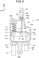
FIG. 4 is a partial sectional view of theCBS module 100. - The saddled vehicle 1 includes the
CBS module 100 that causes both of thefront wheel brake 91 and the rear wheel brake 92 to interlock and operate when theleft brake lever 94 functioning as a rear wheel brake operator is operated. - The
left brake cable 96, the front interlockingbrake cable 97, and the rearinterlocking brake cable 98 are connected to theCBS module 100. The brake cables (the hoses) 96, 97, and 98 have cable structures obtained by covering the circumferences ofinner cables outer cables right brake cable 95 not shown inFIG. 4 also has a cable structure obtained by covering the circumference of an inner cable with an outer cable. - The
CBS module 100 includes anequalizer box 101. Theequalizer box 101 is formed in a rectangular parallelepiped box shape. Anupper fixing section 100a is formed in a front upper part of theequalizer box 101. Alower fixing section 100b extending downward is formed in the lower center of theequalizer box 101. TheCBS module 100 is fixed to thesteering system 9 by theupper fixing section 100a and thelower fixing section 100b. - An equalizer (a braking force adjusting device main body) 102 is disposed on the inside of the
equalizer box 101. - An input connecting section (a braking force input terminal) 103 is provided in an upper part of the
equalizer box 101. Theleft brake cable 96 is connected to theinput connecting section 103. Theouter cable 96b is fixed by an adjustbolt 103a and alock nut 103b. - A front wheel output connecting section (a front-wheel-side braking force output terminal) 104 is provided on a lower part front side of the
equalizer box 101. The frontinterlocking brake cable 97 is connected to a front wheeloutput connecting section 104. Theouter cable 97b is fixed to the front wheeloutput connecting section 104. - A rear wheel output connecting section (a rear-wheel-side braking force output terminal) 105 is provided on a lower part rear side of the
equalizer box 101. The rearinterlocking brake cable 98 is connected to the rear wheeloutput connecting section 105. Theouter cable 98b is fixed to the rear wheeloutput connecting section 105. - The
equalizer 102 includes anarm 111. Thearm 111 extends along the inside of theequalizer box 101. Theinner cable 96a of theleft brake cable 96 is connected to anintermediate section 111a in the longitudinal direction substantial center of thearm 111. Theinner cable 97a of the front interlockingbrake cable 97 is connected to afront end portion 111b of thearm 111. Theinner cable 98a of the rearinterlocking brake cable 98 is connected to arear end portion 111c of thearm 111. Theinner cables shaft members arm 111 is capable of inclining with respect to theinner cables - A sliding
section 97d extending upward is coupled to theshaft member 97c of thefront end portion 111b. Aspring 112 is disposed above the slidingsection 97d. Thespring 112 urges thefront end portion 111b of thearm 111 downward via the slidingsection 97d. A restrictingsection 101a recessed downward is formed in theequalizer box 101 above therear end portion 111c of thearm 111. Therear end portion 111c of thearm 111 is capable of coming into contact with the restrictingsection 101a. - When the
left brake lever 94 is operated, theinner cable 96a of theleft brake cable 96 is towed upward and theequalizer 102 moves upward. Therefore, theinner cable 97a of the front interlockingbrake cable 97 and theinner cable 98a of the rearinterlocking brake cable 98 are towed upward. Both of thefront wheel brake 91 and the rear wheel brake 92 interlock and operate. - At this time, when an operation amount of the
left brake lever 94 is small, since thefront end portion 111b of thearm 111 is urged by thespring 112, thefront end portion 111b less easily moves upward. A towing amount of the front interlockingbrake cable 97 is smaller than a towing amount of the rearinterlocking brake cable 98. When the operation amount of theleft brake lever 94 is large, theinner cable 96a of theleft brake cable 96 is further towed. Therefore, therear end portion 111c of theequalizer 102 comes into contact with the restrictingsection 101a. Theequalizer 102 pivots with therear end portion 111c as a pivoting center. Thefront end portion 111b ascends resisting an urging force of thespring 112. Therefore, theinner cable 97a of the front interlockingbrake cable 97 is towed. In this way, theCBS module 100 adjusts the towing amounts of the front interlockingbrake cable 97 and the rearinterlocking brake cable 98 and adjusts braking forces of thefront wheel brake 91 and the rear wheel brake 92 according to the operation amount of theleft brake lever 94. -
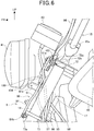
FIGS. 5 and6 are explanatory diagrams of theCBS module 100 and astay 80 in thesteering system 9.FIG. 5 is a view of theCBS module 100 and thestay 80 viewed from the front side orthogonal to thefront forks 14.FIG. 6 is a view of theCBS module 100 and thestay 80 viewed further from the left side than thefront forks 14 on the left side. InFIGS. 5 and6 , illustration of thevehicle body cover 16, the inner tubes of thefront forks 14, and the like on the front side is omitted. - The
CBS module 100 is supported by thetop bridge 72 and thebottom bridge 73 via thestay 80. - The
stay 80 includes a pair of left and right fixing bars 81 and anupper cross bar 82, alower cross bar 83, and across plate 84 supported between the left and right fixing bars 81. - The left and right fixing bars 81 are bar-like members long in the up-down direction and are formed symmetrically. The left and right fixing bars 81 are respectively disposed along the vehicle width direction inner sides of the left and right
front forks 14. -
Upper fixing sections 81a are formed at the upper ends of the left and right fixing bars 81. As shown inFIG. 6 , theupper fixing sections 81a are fixed to top fixingpieces 72a of thetop bridge 72. Thetop fixing pieces 72a are formed in a plate shape bending downward from the front end edge of thetop bridge 72. A pair of thetop fixing pieces 72a is formed on the left and the right. Theupper fixing sections 81a of thestay 80 are rubber-mounted on thetop fixing pieces 72a.Reference sign 72b denotes rubber. - Lower fixing
sections 81b are formed at the lower ends of the left and right fixing bars 81. Thelower fixing sections 81b are fixed tobottom fixing pieces 73a of thebottom bridge 73. Thebottom fixing pieces 73a are formed in a plate shape bending downward from the front end edge of thebottom bridge 73. A pair of thebottom fixing pieces 73a is formed on the left and the right. Thelower fixing sections 81b of thestay 80 are ridge-mounted on thebottom fixing pieces 73a. - The
stay 80 is fixed to thesteering system 9 by theupper fixing sections 81a and thelower fixing sections 81b. - As shown in
FIG. 5 , theupper cross bar 82 extends to the left and the right along thetop bridge 72. Amodule fixing section 82b having an L shape in section is provided in the left-right direction center of theupper cross bar 82. Themodule fixing section 82b is fixed to a lower part of theupper cross bar 82. Themodule fixing section 82b includes a fixingsurface 82c further inclining to the left toward the rear. Theupper fixing section 100a of theCBS module 100 is bolted to the fixingsurface 82c. - The
lower cross bar 83 extends in the left-right direction substantially in the center in the up-down direction between thetop bridge 72 and thebottom bridge 73. A swellingsection 83a bending to swell forward is formed in the left section of thelower cross bar 83. The swellingsection 83a is formed to correspond to a position further on the left side (one side in a vehicle width direction) than thehead pipe 17. Amodule fixing section 83b having an L shape in section is supported by the swellingsection 83a. Themodule fixing section 83b includes a fixingsurface 83c inclining further to the left toward the rear. Thelower fixing section 100b of theCBS module 100 is bolted to the fixingsurface 83c. - The
CBS module 100 is connected to thestay 80 by theupper fixing section 100a and thelower fixing section 100b. A connecting part of theCBS module 100 and thestay 80 is present below thetop bridge 72. Therefore, the heavy objects are disposed in a lower part. A steering function of thesteering system 9 is improved. TheCBS module 100 is disposed between the twofront forks 14. Therefore, theft of theCBS module 100 is easily prevented. Further, in theCBS module 100, thelower fixing section 100b is fixed to thelower cross bar 83 and disposed near an upper part of thehead pipe 17. Therefore, it is easy to secure the distance between thelower fixing section 100b and themain frame 18 on the lower side. It is possible to secure a large curvature radius of bending of the rearinterlocking brake cable 98 guided along themain frame 18. -
FIG. 7 is a plan view of the main part of the saddled vehicle.FIG. 8 is a VIII-VIII line sectional view ofFIG. 1 . InFIG. 7 , illustration of thevehicle body cover 16, the inner tubes of thefront forks 14, and the like on the front side is omitted. - The
CBS module 100 is set on the rear side of theswelling section 83a of thelower cross bar 83. TheCBS module 100 further inclines to the left side toward the rear. TheCBS module 100 is disposed to incline between the twofront forks 14 to thereby be set such that, as shown inFIG. 8 , a distance L2 between the rear wheeloutput connecting section 105 and the rotation center of the steeringshaft 71 is smaller than a distance L1 between the front wheeloutput connecting section 104 and the rotation center of the steeringshaft 71. Since the rear wheeloutput connecting section 105 is disposed in a position closer to thehead pipe 17 than the front wheeloutput connecting section 104, the rear wheeloutput connecting section 105 is close to the rotation center of the steeringshaft 71. The rearinterlocking brake cable 98 extending from the rear wheeloutput connecting section 105 has a small rotation radius during the rotation of thesteering system 9. It is possible to reduce a position change and reduce the influence of steering. - As shown in
FIG. 7 , theright brake cable 95, one end of which is connected to theright brake lever 93, is held by aU-shaped cable guide 15d provided on the right side of thehandlebar 15 and aU-shaped cable guide 82a provided in thestay 80. Theright brake cable 95 is routed toward a space between thehead pipe 17 and theCBS module 100. As shown inFIG. 2 , theright brake cable 95 passes between thehead pipe 17 and theCBS module 100. Then, theright brake cable 95 is drawn around to be rear in thefront fork 14 on the left side, held by anannular cable guide 73b provided in the left section of thebottom bridge 73, and routed toward the rear left section of thefront fender 51. Theright brake cable 95 routed to thefront fender 51 is held by anannular cable guide 51a provided in the rear left section of thefront fender 51 and routed toward thefront wheel brake 91. The other end of theright brake cable 95 is connected to thebrake arm 91b of thefront wheel brake 91. - The
right brake cable 95 is held by the cable guides 15d, 82a, 73b, and 51a provided in thesteering system 9. Theright brake cable 95 is capable of rotating integrally with thesteering system 9. The influence of steering is reduced. - As shown in
FIG. 7 , theleft brake cable 96, one end of which is connected to theleft brake lever 94, is held by aU-shaped cable guide 15e provided on the left side of thehandlebar 15. The other end of theleft brake cable 96 is connected to theinput connecting section 103 of theCBS module 100. Theinput connecting section 103 is located substantially symmetrically with respect to the position of thecable guide 82a on the right side. - As shown in
FIG. 6 , the front interlockingbrake cable 97, one end of which is connected to the front wheeloutput connecting section 104 of theCBS module 100, extends rearward and downward on the vehicle width direction inner side of thefront fork 14 on the left side. As shown inFIG. 2 , the front interlockingbrake cable 97 is held by the cable guides 73b and 51a. The other end of the front interlockingbrake cable 97 is connected to thebrake arm 91b of thefront wheel brake 91. - The
left brake cable 96 and the front interlockingbrake cable 97 are held by and connected to the cable guides 15d, 82a, 73b, and 51a provided in thesteering system 9 and theCBS module 100 supported by thesteering system 9. Theleft brake cable 96 and the front interlockingbrake cable 97 are capable of rotating integrally with thesteering system 9. The influence of steering is reduced. - As shown in
FIG. 2 , the rearinterlocking brake cable 98, one end of which is connected to the rear wheeloutput connecting section 105 of theCBS module 100, is routed to the left side (one side in the vehicle width direction) of themain frame 18. - The
CBS module 100, to which one end of the rearinterlocking brake cable 98 is connected, is also set on the left side of thehead pipe 17. Laying of the rearinterlocking brake cable 98 from theCBS module 100 to themain frame 18 is improved. - The rear
interlocking brake cable 98 routed to themain frame 18 is held by anannular cable guide 18a on the left side and routed toward the rear wheel brake 92 along thevehicle body frame 12. The other end of the rearinterlocking brake cable 98 is connected to thebrake arm 92b. - The rear
interlocking brake cable 98 is routed across thesteering system 9 and thevehicle body frame 12. Therefore, when thesteering system 9 pivots, a positional relation with a fixing part on thevehicle body frame 12 side changes. Since the rear wheeloutput connecting section 105 is close to the axis of thehead pipe 17, when thesteering system 9 pivots, a rotation radius of the rear wheeloutput connecting section 105 is small. It is possible to reduce a position change with respect to thevehicle body frame 12. Therefore, it is possible to reduce the influence of steering on the rearinterlocking brake cable 98. -
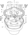
FIG. 9 is a sectional view of the main part of the saddled vehicle 1 and is a sectional view of the right side viewed further from the left side than thehead pipe 17. - The
headlight 41, theheadlight cover 44, and thefront cover 46 are supported by thestay 80. - The
front cover 46 covers an upper part of thesteering system 9. Thefront cover 46 covers a lower part of theheadlight 41 from the front and covers the left and rightfront forks 14 from the vehicle width direction outer side. Afront section 86 of thefront cover 46 is fixed to thecross plate 84. Thefront cover 46 is fixed to fixingsections 81c or the like provided on the left and the right of thestay 80. - The
headlight cover 44 is disposed in the front of thefront cover 46. Theheadlight cover 44 covers the outer circumference of theheadlight 41. Theheadlight cover 44 is fixed to an upper part 46a of thefront cover 46. Theheadlight cover 44 is fixed to thefixing section 81c of thestay 80 together with thefront cover 46. Theheadlight cover 44 is fixed to thefront section 86 of thefront cover 46. - The
headlight 41 is supported on theheadlight cover 44. Theheadlight 41 is supported on theheadlight cover 44 by an engagingmember 41a in an upper part. Theheadlight 41 is fixed to thefront section 86 of thefront cover 46 together with theheadlight cover 44 by abolt 41b in a lower part. - As shown in
FIGS. 8 and9 , theCBS module 100 is fixed to thestay 80, which supports theheadlight 41, to thereby be covered by theheadlight cover 44 behind theheadlight 41. TheCBS module 100 is covered by thefront cover 46 and themeter cover 45 as well. Therefore, it is possible to prevent exposure of theCBS module 100 without separately providing a cover for protection that protects theCBS module 100. External appearance is improved. Moreover, theCBS module 100 is disposed between the pair of left and rightfront forks 14 on the rear side of theswelling section 83a of thestay 80. Antitheft properties are improved. - As shown in
FIG. 9 , themeter device 43 is disposed behind and above theheadlight 41 and above theCBS module 100. The periphery of an upper part of themeter device 43 is covered with themeter cover 45. - The
meter device 43 is present above theCBS module 100. Therefore, it is possible to protect theCBS module 100 from above with themeter device 43 and themeter cover 45. - The
meter device 43 is a mechanical speed meter. Ameter cable 99 is connected to themeter device 43. As shown inFIGS. 2 and3 , themeter cable 99 extends downward from themeter device 43. Themeter cable 99 is routed downward through an upper front of theupper cross bar 82 of thestay 80 and the front side of theCBS module 100. Themeter cable 99 passes the rear of thelower cross bar 83 and then passes the cable guides 73b and 51a together with the front interlockingbrake cable 97. Themeter cable 99 is connected to a speed meter gear (not shown inFIGS. 2 and3 ) disposed in thefront wheel 2. - As explained above, with the saddled vehicle in this embodiment applied with the present invention, in the saddled vehicle 1 including the
head pipe 17, thetop bridge 72 and thebottom bridge 73 pivotally supported by thehead pipe 17 to hold thefront forks 14, theheadlight 41 connected to thetop bridge 72 and thebottom bridge 73 via thestay 80, theheadlight cover 44 that covers the rear of theheadlight 41, and theCBS module 100 that adjusts braking forces applied to thefront wheel 2 rotatably supported by thefront forks 14 and therear wheel 3, theCBS module 100 is connected to thestay 80. Therefore, since theCBS module 100 is covered with theheadlight cover 44 behind theheadlight 41, it is possible to prevent exposure of theCBS module 100 without separately providing a cover for protection. By providing theCBS module 100 in thesteering system 9, it is possible to reduce the influence of steering on theleft brake cable 96 connected to thehandlebar 15 and thefront wheel 2 and the front interlockingbrake cable 97. - In this embodiment, the
CBS module 100 includes the front wheeloutput connecting section 104 that applies a braking force to thefront wheel 2 and the rear wheeloutput connecting section 105 that applies a braking force to therear wheel 3. The rear wheeloutput connecting section 105 is disposed in a position closer to thehead pipe 17 than the front wheeloutput connecting section 104. Therefore, by disposing the rear wheeloutput connecting section 105 in a position close to the rotation center of thesteering system 9, it is possible to reduce the influence of steering. - In this embodiment, the rear
interlocking brake cable 98 extending from the rear wheeloutput connecting section 105 to therear wheel 3 is routed to the left side of themain frame 18 extending backward from thehead pipe 17. TheCBS module 100 is set on the left side with respect to thestay 80. Therefore, laying of the rearinterlocking brake cable 98 from theCBS module 100 to themain frame 18 is improved. - In this embodiment, the
CBS module 100 is disposed near an upper part of thehead pipe 17. Therefore, it is possible to secure a large curvature radius of bending of the rearinterlocking brake cable 98 guided along themain frame 18. - In this embodiment, the
meter device 43 is provided behind and above theheadlight 41 and above theCBS module 100. Therefore, it is possible to protect theCBS module 100 from above. - In this embodiment, the
CBS module 100 is disposed between the twofront forks 14. Therefore, it is possible to improve antitheft properties concerning theCBS module 100. - The embodiment explained above only indicates a form of the present invention. Modifications and applications of the embodiment are optionally possible without departing from the spirit of the present invention.
- For example, in the embodiment, the configuration of the
front wheel brake 91, the rear wheel brake 92, and theCBS module 100 including the wire-type cables is explained. However, the configuration of thefront wheel brake 91, the rear wheel brake 92, and theCBS module 100 may be a configuration by hydraulic pressure. The configuration including a brake by hydraulic pressure may be adopted only in either one of thefront wheel brake 91 and the rear wheel brake 92. Accordingly, thehoses 96 to 98 are not limited to the wire-type cable. A brake hose filled with brake fluid may be used. - The present invention is not limitedly applied to the motorcycle and is applicable to saddled vehicles other than the motorcycle. Note that the saddled vehicles include all vehicles on which riders ride while straddling on vehicle bodies. The saddled vehicles are vehicles including not only the motorcycle (including a motor-assisted bicycle) but also a three-wheel vehicle and a four-wheel vehicle classified into an ATV (an off-road traveling vehicle).
-
- 2
- wheel, front wheel
- 3
- rear wheel
- 14
- front fork
- 17
- head pipe
- 18
- main frame
- 41
- headlight
- 43
- meter device
- 44
- headlight cover
- 72, 73
- bridge
- 80
- stay
- 98
- hose
- 100
- braking force adjusting device
- 104
- front-wheel-side braking force output terminal
- 105
- rear-wheel-side braking force output terminal
Claims (6)
- A saddled vehicle comprising:a head pipe (17);bridges (72, 73) pivotally supported by the head pipe (17) to hold front forks (14);a headlight (41) connected to the bridges (72, 73) via a stay (80);a headlight cover (44) that covers a rear of the headlight (41); anda braking force adjusting device (100) that adjusts a braking force applied to a wheel (2) rotatably supported by the front forks (14), whereinthe braking force adjusting device (100) is connected to the stay (80).
- The saddled vehicle according to claim 1, wherein the braking force adjusting device (100) includes:a front-wheel-side braking force output terminal (104) that applies a braking force to a front wheel (2); anda rear-wheel-side braking force output terminal (105) that applies a braking force to a rear wheel (3), andthe rear-wheel-side braking force output terminal (105) is disposed in a position closer to the head pipe (17) than the front-wheel-side braking force output terminal (104).
- The saddled vehicle according to claim 2, wherein
a hose (98) extending from the rear-wheel-side braking force output terminal (105) to a rear wheel (3) is routed to one side in a vehicle width direction of a main frame (18) extending backward from the head pipe (17), and
the braking force adjusting device (100) is set on one side in the vehicle width direction with respect to the stay (80). - The saddled vehicle according to any one of claims 1 to 3, wherein the braking force adjusting device (100) is disposed near an upper part of the head pipe (17).
- The saddled vehicle according to any one of claims 1 to 4, wherein the saddled vehicle includes a meter device (43) behind and above the headlight (41) and above the braking force adjusting device (100).
- The saddled vehicle according to any one of claims 1 to 5, wherein the braking force adjusting device (100) is disposed between a pair of the front forks (14).
Applications Claiming Priority (2)
| Application Number | Priority Date | Filing Date | Title |
|---|---|---|---|
| IN201811004281 | 2018-02-05 | ||
| PCT/JP2018/043709 WO2019150730A1 (en) | 2018-02-05 | 2018-11-28 | Saddled vehicle |
Publications (2)
| Publication Number | Publication Date |
|---|---|
| EP3705389A1 true EP3705389A1 (en) | 2020-09-09 |
| EP3705389A4 EP3705389A4 (en) | 2021-03-03 |
Family
ID=67479673
Family Applications (1)
| Application Number | Title | Priority Date | Filing Date |
|---|---|---|---|
| EP18903737.7A Withdrawn EP3705389A4 (en) | 2018-02-05 | 2018-11-28 | Saddled vehicle |
Country Status (4)
| Country | Link |
|---|---|
| EP (1) | EP3705389A4 (en) |
| JP (1) | JP6951477B2 (en) |
| CN (1) | CN111655571B (en) |
| WO (1) | WO2019150730A1 (en) |
Family Cites Families (25)
| Publication number | Priority date | Publication date | Assignee | Title |
|---|---|---|---|---|
| JP3149704B2 (en) * | 1994-10-12 | 2001-03-26 | スズキ株式会社 | Headlight support structure for motorcycles |
| JP3875406B2 (en) * | 1998-07-21 | 2007-01-31 | 本田技研工業株式会社 | Front-rear brake system for motorcycles |
| JP4059996B2 (en) * | 1998-11-30 | 2008-03-12 | 本田技研工業株式会社 | Motorcycle brake equipment |
| JP4233678B2 (en) * | 1999-04-26 | 2009-03-04 | 本田技研工業株式会社 | Interlocking brake device for motorcycles |
| JP3445760B2 (en) * | 1999-08-30 | 2003-09-08 | 日本フレックス工業株式会社 | Method and apparatus for adjusting front and rear wheel brakes of a bicycle |
| CN2411961Y (en) * | 1999-12-24 | 2000-12-27 | 光阳工业股份有限公司 | Motorcycle linkage brake device |
| JP4306442B2 (en) * | 2003-12-19 | 2009-08-05 | スズキ株式会社 | Motorcycle with anti-lock brake device |
| US7387347B2 (en) * | 2005-06-28 | 2008-06-17 | Harley-Davidson Motor Company Group, Inc. | Brake system for a motorcycle and a method of filling the brake system |
| JP2007161097A (en) * | 2005-12-14 | 2007-06-28 | Yamaha Motor Co Ltd | Motorcycle |
| JP2009161011A (en) * | 2007-12-28 | 2009-07-23 | Yamaha Motor Co Ltd | Motorcycle |
| JP5086831B2 (en) * | 2008-02-19 | 2012-11-28 | 本田技研工業株式会社 | Motorcycle |
| JP5205168B2 (en) * | 2008-07-31 | 2013-06-05 | 本田技研工業株式会社 | Body front support structure |
| JP5378121B2 (en) * | 2009-09-04 | 2013-12-25 | 本田技研工業株式会社 | Parking brake lever device for vehicles |
| JP5364613B2 (en) * | 2010-02-17 | 2013-12-11 | 本田技研工業株式会社 | Saddle riding vehicle |
| JP5572618B2 (en) * | 2011-11-16 | 2014-08-13 | 本田技研工業株式会社 | Motorcycle |
| JP5853663B2 (en) * | 2011-12-16 | 2016-02-09 | スズキ株式会社 | Brake piping structure of motorcycle |
| JP5855980B2 (en) * | 2012-03-08 | 2016-02-09 | 本田技研工業株式会社 | Motorcycle |
| CN104203737B (en) * | 2012-03-21 | 2017-03-01 | 本田技研工业株式会社 | Straddle-type vehicle |
| EP2891600B1 (en) * | 2012-08-29 | 2016-12-07 | Honda Motor Co., Ltd. | Two-Wheeled Automobile |
| JP6130222B2 (en) * | 2013-05-24 | 2017-05-17 | 川崎重工業株式会社 | Motorcycle harness support structure |
| US9428235B2 (en) * | 2013-07-01 | 2016-08-30 | Yamaha Hatsudoki Kabushiki Kaisha | Vehicle |
| JP2015085749A (en) * | 2013-10-29 | 2015-05-07 | ヤマハ発動機株式会社 | Saddle riding vehicle |
| JP6133923B2 (en) | 2015-03-25 | 2017-05-24 | 本田技研工業株式会社 | Saddle riding vehicle |
| JP6356627B2 (en) * | 2015-03-31 | 2018-07-11 | 本田技研工業株式会社 | A saddle-ride type vehicle equipped with a blinker |
| CN106904241A (en) * | 2017-04-24 | 2017-06-30 | 天津微驰科技有限公司 | Electric bicycle control system and electric bicycle |
-
2018
- 2018-11-28 EP EP18903737.7A patent/EP3705389A4/en not_active Withdrawn
- 2018-11-28 CN CN201880088032.8A patent/CN111655571B/en active Active
- 2018-11-28 WO PCT/JP2018/043709 patent/WO2019150730A1/en not_active Ceased
- 2018-11-28 JP JP2019568889A patent/JP6951477B2/en not_active Expired - Fee Related
Also Published As
| Publication number | Publication date |
|---|---|
| BR112020013401A2 (en) | 2020-12-01 |
| EP3705389A4 (en) | 2021-03-03 |
| WO2019150730A1 (en) | 2019-08-08 |
| CN111655571B (en) | 2022-02-11 |
| JP6951477B2 (en) | 2021-10-20 |
| CN111655571A (en) | 2020-09-11 |
| JPWO2019150730A1 (en) | 2020-12-10 |
Similar Documents
| Publication | Publication Date | Title |
|---|---|---|
| JP5507300B2 (en) | Braking device for saddle-ride type vehicles | |
| EP2716536A1 (en) | Two-wheeled motor vehicle | |
| JP6800197B2 (en) | Saddle-type vehicle | |
| WO2015079426A1 (en) | Swing arm for a vehicle | |
| CN100406338C (en) | Rocker structure | |
| JP2006232061A (en) | Saddle riding type rough terrain vehicle | |
| EP3798109B1 (en) | Straddled vehicle | |
| JP6773704B2 (en) | Rear brake hose layout structure for saddle-riding vehicles | |
| EP3705389A1 (en) | Saddled vehicle | |
| JP5546904B2 (en) | Saddle riding vehicle | |
| JP2017065405A (en) | Front structure of saddle-ride type vehicle | |
| JP7061670B2 (en) | Saddle-type vehicle | |
| US11535336B2 (en) | Saddle riding vehicle | |
| JP7730879B2 (en) | Saddle-type vehicle | |
| JP2023131270A (en) | Saddle-riding type vehicle | |
| CN110573417B (en) | Front and rear interlocking brake device for straddle-type vehicle | |
| JP7663615B2 (en) | Saddle-type vehicle | |
| JP7771242B2 (en) | Saddle-type vehicle | |
| JP6890627B2 (en) | Saddle-type vehicle | |
| CN220577431U (en) | Motorcycle | |
| JP7543369B2 (en) | Saddle-type vehicle | |
| JP7787221B2 (en) | Saddle-type vehicle | |
| BR112020013401B1 (en) | SADDLE MOUNTING VEHICLE | |
| WO2026013748A1 (en) | Saddled vehicle | |
| JP2024114504A (en) | Saddle type vehicle |
Legal Events
| Date | Code | Title | Description |
|---|---|---|---|
| STAA | Information on the status of an ep patent application or granted ep patent |
Free format text: STATUS: THE INTERNATIONAL PUBLICATION HAS BEEN MADE |
|
| PUAI | Public reference made under article 153(3) epc to a published international application that has entered the european phase |
Free format text: ORIGINAL CODE: 0009012 |
|
| STAA | Information on the status of an ep patent application or granted ep patent |
Free format text: STATUS: REQUEST FOR EXAMINATION WAS MADE |
|
| 17P | Request for examination filed |
Effective date: 20200602 |
|
| AK | Designated contracting states |
Kind code of ref document: A1 Designated state(s): AL AT BE BG CH CY CZ DE DK EE ES FI FR GB GR HR HU IE IS IT LI LT LU LV MC MK MT NL NO PL PT RO RS SE SI SK SM TR |
|
| AX | Request for extension of the european patent |
Extension state: BA ME |
|
| A4 | Supplementary search report drawn up and despatched |
Effective date: 20210201 |
|
| RIC1 | Information provided on ipc code assigned before grant |
Ipc: B62L 3/08 20060101ALI20210126BHEP Ipc: B62L 5/20 20060101ALI20210126BHEP Ipc: B62K 19/38 20060101AFI20210126BHEP Ipc: B62L 3/02 20060101ALI20210126BHEP |
|
| DAV | Request for validation of the european patent (deleted) | ||
| DAX | Request for extension of the european patent (deleted) | ||
| STAA | Information on the status of an ep patent application or granted ep patent |
Free format text: STATUS: EXAMINATION IS IN PROGRESS |
|
| 17Q | First examination report despatched |
Effective date: 20210702 |
|
| GRAP | Despatch of communication of intention to grant a patent |
Free format text: ORIGINAL CODE: EPIDOSNIGR1 |
|
| STAA | Information on the status of an ep patent application or granted ep patent |
Free format text: STATUS: GRANT OF PATENT IS INTENDED |
|
| INTG | Intention to grant announced |
Effective date: 20220311 |
|
| STAA | Information on the status of an ep patent application or granted ep patent |
Free format text: STATUS: THE APPLICATION IS DEEMED TO BE WITHDRAWN |
|
| 18D | Application deemed to be withdrawn |
Effective date: 20220722 |