EP3705271B1 - Procédé pour le collage d'un matériau composite - Google Patents
Procédé pour le collage d'un matériau composite Download PDFInfo
- Publication number
- EP3705271B1 EP3705271B1 EP18885792.4A EP18885792A EP3705271B1 EP 3705271 B1 EP3705271 B1 EP 3705271B1 EP 18885792 A EP18885792 A EP 18885792A EP 3705271 B1 EP3705271 B1 EP 3705271B1
- Authority
- EP
- European Patent Office
- Prior art keywords
- composite material
- resin
- protruding
- protruding members
- reinforcing fibers
- Prior art date
- Legal status (The legal status is an assumption and is not a legal conclusion. Google has not performed a legal analysis and makes no representation as to the accuracy of the status listed.)
- Active
Links
Images


Classifications
-
- B—PERFORMING OPERATIONS; TRANSPORTING
- B29—WORKING OF PLASTICS; WORKING OF SUBSTANCES IN A PLASTIC STATE IN GENERAL
- B29C—SHAPING OR JOINING OF PLASTICS; SHAPING OF MATERIAL IN A PLASTIC STATE, NOT OTHERWISE PROVIDED FOR; AFTER-TREATMENT OF THE SHAPED PRODUCTS, e.g. REPAIRING
- B29C65/00—Joining or sealing of preformed parts, e.g. welding of plastics materials; Apparatus therefor
- B29C65/56—Joining or sealing of preformed parts, e.g. welding of plastics materials; Apparatus therefor using mechanical means or mechanical connections, e.g. form-fits
- B29C65/562—Joining or sealing of preformed parts, e.g. welding of plastics materials; Apparatus therefor using mechanical means or mechanical connections, e.g. form-fits using extra joining elements, i.e. which are not integral with the parts to be joined
- B29C65/564—Joining or sealing of preformed parts, e.g. welding of plastics materials; Apparatus therefor using mechanical means or mechanical connections, e.g. form-fits using extra joining elements, i.e. which are not integral with the parts to be joined hidden in the joint, e.g. dowels or Z-pins
-
- B—PERFORMING OPERATIONS; TRANSPORTING
- B29—WORKING OF PLASTICS; WORKING OF SUBSTANCES IN A PLASTIC STATE IN GENERAL
- B29C—SHAPING OR JOINING OF PLASTICS; SHAPING OF MATERIAL IN A PLASTIC STATE, NOT OTHERWISE PROVIDED FOR; AFTER-TREATMENT OF THE SHAPED PRODUCTS, e.g. REPAIRING
- B29C70/00—Shaping composites, i.e. plastics material comprising reinforcements, fillers or preformed parts, e.g. inserts
- B29C70/68—Shaping composites, i.e. plastics material comprising reinforcements, fillers or preformed parts, e.g. inserts by incorporating or moulding on preformed parts, e.g. inserts or layers, e.g. foam blocks
- B29C70/72—Encapsulating inserts having non-encapsulated projections, e.g. extremities or terminal portions of electrical components
-
- B—PERFORMING OPERATIONS; TRANSPORTING
- B29—WORKING OF PLASTICS; WORKING OF SUBSTANCES IN A PLASTIC STATE IN GENERAL
- B29C—SHAPING OR JOINING OF PLASTICS; SHAPING OF MATERIAL IN A PLASTIC STATE, NOT OTHERWISE PROVIDED FOR; AFTER-TREATMENT OF THE SHAPED PRODUCTS, e.g. REPAIRING
- B29C65/00—Joining or sealing of preformed parts, e.g. welding of plastics materials; Apparatus therefor
- B29C65/02—Joining or sealing of preformed parts, e.g. welding of plastics materials; Apparatus therefor by heating, with or without pressure
- B29C65/06—Joining or sealing of preformed parts, e.g. welding of plastics materials; Apparatus therefor by heating, with or without pressure using friction, e.g. spin welding
- B29C65/0609—Joining or sealing of preformed parts, e.g. welding of plastics materials; Apparatus therefor by heating, with or without pressure using friction, e.g. spin welding characterised by the movement of the parts to be joined
- B29C65/0618—Linear
-
- B—PERFORMING OPERATIONS; TRANSPORTING
- B29—WORKING OF PLASTICS; WORKING OF SUBSTANCES IN A PLASTIC STATE IN GENERAL
- B29C—SHAPING OR JOINING OF PLASTICS; SHAPING OF MATERIAL IN A PLASTIC STATE, NOT OTHERWISE PROVIDED FOR; AFTER-TREATMENT OF THE SHAPED PRODUCTS, e.g. REPAIRING
- B29C65/00—Joining or sealing of preformed parts, e.g. welding of plastics materials; Apparatus therefor
- B29C65/02—Joining or sealing of preformed parts, e.g. welding of plastics materials; Apparatus therefor by heating, with or without pressure
- B29C65/34—Joining or sealing of preformed parts, e.g. welding of plastics materials; Apparatus therefor by heating, with or without pressure using heated elements which remain in the joint, e.g. "verlorenes Schweisselement"
- B29C65/36—Joining or sealing of preformed parts, e.g. welding of plastics materials; Apparatus therefor by heating, with or without pressure using heated elements which remain in the joint, e.g. "verlorenes Schweisselement" heated by induction
-
- B—PERFORMING OPERATIONS; TRANSPORTING
- B29—WORKING OF PLASTICS; WORKING OF SUBSTANCES IN A PLASTIC STATE IN GENERAL
- B29C—SHAPING OR JOINING OF PLASTICS; SHAPING OF MATERIAL IN A PLASTIC STATE, NOT OTHERWISE PROVIDED FOR; AFTER-TREATMENT OF THE SHAPED PRODUCTS, e.g. REPAIRING
- B29C65/00—Joining or sealing of preformed parts, e.g. welding of plastics materials; Apparatus therefor
- B29C65/48—Joining or sealing of preformed parts, e.g. welding of plastics materials; Apparatus therefor using adhesives, i.e. using supplementary joining material; solvent bonding
- B29C65/4805—Joining or sealing of preformed parts, e.g. welding of plastics materials; Apparatus therefor using adhesives, i.e. using supplementary joining material; solvent bonding characterised by the type of adhesives
- B29C65/481—Non-reactive adhesives, e.g. physically hardening adhesives
- B29C65/4815—Hot melt adhesives, e.g. thermoplastic adhesives
-
- B—PERFORMING OPERATIONS; TRANSPORTING
- B29—WORKING OF PLASTICS; WORKING OF SUBSTANCES IN A PLASTIC STATE IN GENERAL
- B29C—SHAPING OR JOINING OF PLASTICS; SHAPING OF MATERIAL IN A PLASTIC STATE, NOT OTHERWISE PROVIDED FOR; AFTER-TREATMENT OF THE SHAPED PRODUCTS, e.g. REPAIRING
- B29C65/00—Joining or sealing of preformed parts, e.g. welding of plastics materials; Apparatus therefor
- B29C65/48—Joining or sealing of preformed parts, e.g. welding of plastics materials; Apparatus therefor using adhesives, i.e. using supplementary joining material; solvent bonding
- B29C65/486—Joining or sealing of preformed parts, e.g. welding of plastics materials; Apparatus therefor using adhesives, i.e. using supplementary joining material; solvent bonding characterised by their physical form being non-liquid, e.g. in the form of granules or powders
-
- B—PERFORMING OPERATIONS; TRANSPORTING
- B29—WORKING OF PLASTICS; WORKING OF SUBSTANCES IN A PLASTIC STATE IN GENERAL
- B29C—SHAPING OR JOINING OF PLASTICS; SHAPING OF MATERIAL IN A PLASTIC STATE, NOT OTHERWISE PROVIDED FOR; AFTER-TREATMENT OF THE SHAPED PRODUCTS, e.g. REPAIRING
- B29C65/00—Joining or sealing of preformed parts, e.g. welding of plastics materials; Apparatus therefor
- B29C65/48—Joining or sealing of preformed parts, e.g. welding of plastics materials; Apparatus therefor using adhesives, i.e. using supplementary joining material; solvent bonding
- B29C65/50—Joining or sealing of preformed parts, e.g. welding of plastics materials; Apparatus therefor using adhesives, i.e. using supplementary joining material; solvent bonding using adhesive tape, e.g. thermoplastic tape; using threads or the like
- B29C65/5007—Joining or sealing of preformed parts, e.g. welding of plastics materials; Apparatus therefor using adhesives, i.e. using supplementary joining material; solvent bonding using adhesive tape, e.g. thermoplastic tape; using threads or the like characterised by the structure of said adhesive tape, threads or the like
- B29C65/5014—Joining or sealing of preformed parts, e.g. welding of plastics materials; Apparatus therefor using adhesives, i.e. using supplementary joining material; solvent bonding using adhesive tape, e.g. thermoplastic tape; using threads or the like characterised by the structure of said adhesive tape, threads or the like being fibre-reinforced
-
- B—PERFORMING OPERATIONS; TRANSPORTING
- B29—WORKING OF PLASTICS; WORKING OF SUBSTANCES IN A PLASTIC STATE IN GENERAL
- B29C—SHAPING OR JOINING OF PLASTICS; SHAPING OF MATERIAL IN A PLASTIC STATE, NOT OTHERWISE PROVIDED FOR; AFTER-TREATMENT OF THE SHAPED PRODUCTS, e.g. REPAIRING
- B29C65/00—Joining or sealing of preformed parts, e.g. welding of plastics materials; Apparatus therefor
- B29C65/48—Joining or sealing of preformed parts, e.g. welding of plastics materials; Apparatus therefor using adhesives, i.e. using supplementary joining material; solvent bonding
- B29C65/50—Joining or sealing of preformed parts, e.g. welding of plastics materials; Apparatus therefor using adhesives, i.e. using supplementary joining material; solvent bonding using adhesive tape, e.g. thermoplastic tape; using threads or the like
- B29C65/5057—Joining or sealing of preformed parts, e.g. welding of plastics materials; Apparatus therefor using adhesives, i.e. using supplementary joining material; solvent bonding using adhesive tape, e.g. thermoplastic tape; using threads or the like positioned between the surfaces to be joined
-
- B—PERFORMING OPERATIONS; TRANSPORTING
- B29—WORKING OF PLASTICS; WORKING OF SUBSTANCES IN A PLASTIC STATE IN GENERAL
- B29C—SHAPING OR JOINING OF PLASTICS; SHAPING OF MATERIAL IN A PLASTIC STATE, NOT OTHERWISE PROVIDED FOR; AFTER-TREATMENT OF THE SHAPED PRODUCTS, e.g. REPAIRING
- B29C66/00—General aspects of processes or apparatus for joining preformed parts
- B29C66/01—General aspects dealing with the joint area or with the area to be joined
- B29C66/05—Particular design of joint configurations
- B29C66/10—Particular design of joint configurations particular design of the joint cross-sections
- B29C66/11—Joint cross-sections comprising a single joint-segment, i.e. one of the parts to be joined comprising a single joint-segment in the joint cross-section
- B29C66/112—Single lapped joints
- B29C66/1122—Single lap to lap joints, i.e. overlap joints
-
- B—PERFORMING OPERATIONS; TRANSPORTING
- B29—WORKING OF PLASTICS; WORKING OF SUBSTANCES IN A PLASTIC STATE IN GENERAL
- B29C—SHAPING OR JOINING OF PLASTICS; SHAPING OF MATERIAL IN A PLASTIC STATE, NOT OTHERWISE PROVIDED FOR; AFTER-TREATMENT OF THE SHAPED PRODUCTS, e.g. REPAIRING
- B29C66/00—General aspects of processes or apparatus for joining preformed parts
- B29C66/01—General aspects dealing with the joint area or with the area to be joined
- B29C66/05—Particular design of joint configurations
- B29C66/303—Particular design of joint configurations the joint involving an anchoring effect
- B29C66/3034—Particular design of joint configurations the joint involving an anchoring effect making use of additional elements, e.g. meshes
- B29C66/30341—Particular design of joint configurations the joint involving an anchoring effect making use of additional elements, e.g. meshes non-integral with the parts to be joined, e.g. making use of extra elements
-
- B—PERFORMING OPERATIONS; TRANSPORTING
- B29—WORKING OF PLASTICS; WORKING OF SUBSTANCES IN A PLASTIC STATE IN GENERAL
- B29C—SHAPING OR JOINING OF PLASTICS; SHAPING OF MATERIAL IN A PLASTIC STATE, NOT OTHERWISE PROVIDED FOR; AFTER-TREATMENT OF THE SHAPED PRODUCTS, e.g. REPAIRING
- B29C66/00—General aspects of processes or apparatus for joining preformed parts
- B29C66/01—General aspects dealing with the joint area or with the area to be joined
- B29C66/341—Measures for intermixing the material of the joint interlayer
-
- B—PERFORMING OPERATIONS; TRANSPORTING
- B29—WORKING OF PLASTICS; WORKING OF SUBSTANCES IN A PLASTIC STATE IN GENERAL
- B29C—SHAPING OR JOINING OF PLASTICS; SHAPING OF MATERIAL IN A PLASTIC STATE, NOT OTHERWISE PROVIDED FOR; AFTER-TREATMENT OF THE SHAPED PRODUCTS, e.g. REPAIRING
- B29C66/00—General aspects of processes or apparatus for joining preformed parts
- B29C66/40—General aspects of joining substantially flat articles, e.g. plates, sheets or web-like materials; Making flat seams in tubular or hollow articles; Joining single elements to substantially flat surfaces
- B29C66/41—Joining substantially flat articles ; Making flat seams in tubular or hollow articles
- B29C66/43—Joining a relatively small portion of the surface of said articles
-
- B—PERFORMING OPERATIONS; TRANSPORTING
- B29—WORKING OF PLASTICS; WORKING OF SUBSTANCES IN A PLASTIC STATE IN GENERAL
- B29C—SHAPING OR JOINING OF PLASTICS; SHAPING OF MATERIAL IN A PLASTIC STATE, NOT OTHERWISE PROVIDED FOR; AFTER-TREATMENT OF THE SHAPED PRODUCTS, e.g. REPAIRING
- B29C66/00—General aspects of processes or apparatus for joining preformed parts
- B29C66/40—General aspects of joining substantially flat articles, e.g. plates, sheets or web-like materials; Making flat seams in tubular or hollow articles; Joining single elements to substantially flat surfaces
- B29C66/41—Joining substantially flat articles ; Making flat seams in tubular or hollow articles
- B29C66/45—Joining of substantially the whole surface of the articles
-
- B—PERFORMING OPERATIONS; TRANSPORTING
- B29—WORKING OF PLASTICS; WORKING OF SUBSTANCES IN A PLASTIC STATE IN GENERAL
- B29C—SHAPING OR JOINING OF PLASTICS; SHAPING OF MATERIAL IN A PLASTIC STATE, NOT OTHERWISE PROVIDED FOR; AFTER-TREATMENT OF THE SHAPED PRODUCTS, e.g. REPAIRING
- B29C66/00—General aspects of processes or apparatus for joining preformed parts
- B29C66/70—General aspects of processes or apparatus for joining preformed parts characterised by the composition, physical properties or the structure of the material of the parts to be joined; Joining with non-plastics material
- B29C66/71—General aspects of processes or apparatus for joining preformed parts characterised by the composition, physical properties or the structure of the material of the parts to be joined; Joining with non-plastics material characterised by the composition of the plastics material of the parts to be joined
-
- B—PERFORMING OPERATIONS; TRANSPORTING
- B29—WORKING OF PLASTICS; WORKING OF SUBSTANCES IN A PLASTIC STATE IN GENERAL
- B29C—SHAPING OR JOINING OF PLASTICS; SHAPING OF MATERIAL IN A PLASTIC STATE, NOT OTHERWISE PROVIDED FOR; AFTER-TREATMENT OF THE SHAPED PRODUCTS, e.g. REPAIRING
- B29C66/00—General aspects of processes or apparatus for joining preformed parts
- B29C66/70—General aspects of processes or apparatus for joining preformed parts characterised by the composition, physical properties or the structure of the material of the parts to be joined; Joining with non-plastics material
- B29C66/72—General aspects of processes or apparatus for joining preformed parts characterised by the composition, physical properties or the structure of the material of the parts to be joined; Joining with non-plastics material characterised by the structure of the material of the parts to be joined
- B29C66/721—Fibre-reinforced materials
- B29C66/7212—Fibre-reinforced materials characterised by the composition of the fibres
-
- B—PERFORMING OPERATIONS; TRANSPORTING
- B29—WORKING OF PLASTICS; WORKING OF SUBSTANCES IN A PLASTIC STATE IN GENERAL
- B29C—SHAPING OR JOINING OF PLASTICS; SHAPING OF MATERIAL IN A PLASTIC STATE, NOT OTHERWISE PROVIDED FOR; AFTER-TREATMENT OF THE SHAPED PRODUCTS, e.g. REPAIRING
- B29C66/00—General aspects of processes or apparatus for joining preformed parts
- B29C66/70—General aspects of processes or apparatus for joining preformed parts characterised by the composition, physical properties or the structure of the material of the parts to be joined; Joining with non-plastics material
- B29C66/72—General aspects of processes or apparatus for joining preformed parts characterised by the composition, physical properties or the structure of the material of the parts to be joined; Joining with non-plastics material characterised by the structure of the material of the parts to be joined
- B29C66/721—Fibre-reinforced materials
- B29C66/7214—Fibre-reinforced materials characterised by the length of the fibres
- B29C66/72141—Fibres of continuous length
-
- B—PERFORMING OPERATIONS; TRANSPORTING
- B29—WORKING OF PLASTICS; WORKING OF SUBSTANCES IN A PLASTIC STATE IN GENERAL
- B29C—SHAPING OR JOINING OF PLASTICS; SHAPING OF MATERIAL IN A PLASTIC STATE, NOT OTHERWISE PROVIDED FOR; AFTER-TREATMENT OF THE SHAPED PRODUCTS, e.g. REPAIRING
- B29C66/00—General aspects of processes or apparatus for joining preformed parts
- B29C66/70—General aspects of processes or apparatus for joining preformed parts characterised by the composition, physical properties or the structure of the material of the parts to be joined; Joining with non-plastics material
- B29C66/73—General aspects of processes or apparatus for joining preformed parts characterised by the composition, physical properties or the structure of the material of the parts to be joined; Joining with non-plastics material characterised by the intensive physical properties of the material of the parts to be joined, by the optical properties of the material of the parts to be joined, by the extensive physical properties of the parts to be joined, by the state of the material of the parts to be joined or by the material of the parts to be joined being a thermoplastic or a thermoset
- B29C66/737—General aspects of processes or apparatus for joining preformed parts characterised by the composition, physical properties or the structure of the material of the parts to be joined; Joining with non-plastics material characterised by the intensive physical properties of the material of the parts to be joined, by the optical properties of the material of the parts to be joined, by the extensive physical properties of the parts to be joined, by the state of the material of the parts to be joined or by the material of the parts to be joined being a thermoplastic or a thermoset characterised by the state of the material of the parts to be joined
- B29C66/7375—General aspects of processes or apparatus for joining preformed parts characterised by the composition, physical properties or the structure of the material of the parts to be joined; Joining with non-plastics material characterised by the intensive physical properties of the material of the parts to be joined, by the optical properties of the material of the parts to be joined, by the extensive physical properties of the parts to be joined, by the state of the material of the parts to be joined or by the material of the parts to be joined being a thermoplastic or a thermoset characterised by the state of the material of the parts to be joined uncured, partially cured or fully cured
- B29C66/73751—General aspects of processes or apparatus for joining preformed parts characterised by the composition, physical properties or the structure of the material of the parts to be joined; Joining with non-plastics material characterised by the intensive physical properties of the material of the parts to be joined, by the optical properties of the material of the parts to be joined, by the extensive physical properties of the parts to be joined, by the state of the material of the parts to be joined or by the material of the parts to be joined being a thermoplastic or a thermoset characterised by the state of the material of the parts to be joined uncured, partially cured or fully cured the to-be-joined area of at least one of the parts to be joined being uncured, i.e. non cross-linked, non vulcanized
- B29C66/73752—General aspects of processes or apparatus for joining preformed parts characterised by the composition, physical properties or the structure of the material of the parts to be joined; Joining with non-plastics material characterised by the intensive physical properties of the material of the parts to be joined, by the optical properties of the material of the parts to be joined, by the extensive physical properties of the parts to be joined, by the state of the material of the parts to be joined or by the material of the parts to be joined being a thermoplastic or a thermoset characterised by the state of the material of the parts to be joined uncured, partially cured or fully cured the to-be-joined area of at least one of the parts to be joined being uncured, i.e. non cross-linked, non vulcanized the to-be-joined areas of both parts to be joined being uncured
-
- B—PERFORMING OPERATIONS; TRANSPORTING
- B29—WORKING OF PLASTICS; WORKING OF SUBSTANCES IN A PLASTIC STATE IN GENERAL
- B29C—SHAPING OR JOINING OF PLASTICS; SHAPING OF MATERIAL IN A PLASTIC STATE, NOT OTHERWISE PROVIDED FOR; AFTER-TREATMENT OF THE SHAPED PRODUCTS, e.g. REPAIRING
- B29C66/00—General aspects of processes or apparatus for joining preformed parts
- B29C66/70—General aspects of processes or apparatus for joining preformed parts characterised by the composition, physical properties or the structure of the material of the parts to be joined; Joining with non-plastics material
- B29C66/73—General aspects of processes or apparatus for joining preformed parts characterised by the composition, physical properties or the structure of the material of the parts to be joined; Joining with non-plastics material characterised by the intensive physical properties of the material of the parts to be joined, by the optical properties of the material of the parts to be joined, by the extensive physical properties of the parts to be joined, by the state of the material of the parts to be joined or by the material of the parts to be joined being a thermoplastic or a thermoset
- B29C66/737—General aspects of processes or apparatus for joining preformed parts characterised by the composition, physical properties or the structure of the material of the parts to be joined; Joining with non-plastics material characterised by the intensive physical properties of the material of the parts to be joined, by the optical properties of the material of the parts to be joined, by the extensive physical properties of the parts to be joined, by the state of the material of the parts to be joined or by the material of the parts to be joined being a thermoplastic or a thermoset characterised by the state of the material of the parts to be joined
- B29C66/7375—General aspects of processes or apparatus for joining preformed parts characterised by the composition, physical properties or the structure of the material of the parts to be joined; Joining with non-plastics material characterised by the intensive physical properties of the material of the parts to be joined, by the optical properties of the material of the parts to be joined, by the extensive physical properties of the parts to be joined, by the state of the material of the parts to be joined or by the material of the parts to be joined being a thermoplastic or a thermoset characterised by the state of the material of the parts to be joined uncured, partially cured or fully cured
- B29C66/73753—General aspects of processes or apparatus for joining preformed parts characterised by the composition, physical properties or the structure of the material of the parts to be joined; Joining with non-plastics material characterised by the intensive physical properties of the material of the parts to be joined, by the optical properties of the material of the parts to be joined, by the extensive physical properties of the parts to be joined, by the state of the material of the parts to be joined or by the material of the parts to be joined being a thermoplastic or a thermoset characterised by the state of the material of the parts to be joined uncured, partially cured or fully cured the to-be-joined area of at least one of the parts to be joined being partially cured, i.e. partially cross-linked, partially vulcanized
-
- B—PERFORMING OPERATIONS; TRANSPORTING
- B29—WORKING OF PLASTICS; WORKING OF SUBSTANCES IN A PLASTIC STATE IN GENERAL
- B29C—SHAPING OR JOINING OF PLASTICS; SHAPING OF MATERIAL IN A PLASTIC STATE, NOT OTHERWISE PROVIDED FOR; AFTER-TREATMENT OF THE SHAPED PRODUCTS, e.g. REPAIRING
- B29C66/00—General aspects of processes or apparatus for joining preformed parts
- B29C66/70—General aspects of processes or apparatus for joining preformed parts characterised by the composition, physical properties or the structure of the material of the parts to be joined; Joining with non-plastics material
- B29C66/73—General aspects of processes or apparatus for joining preformed parts characterised by the composition, physical properties or the structure of the material of the parts to be joined; Joining with non-plastics material characterised by the intensive physical properties of the material of the parts to be joined, by the optical properties of the material of the parts to be joined, by the extensive physical properties of the parts to be joined, by the state of the material of the parts to be joined or by the material of the parts to be joined being a thermoplastic or a thermoset
- B29C66/739—General aspects of processes or apparatus for joining preformed parts characterised by the composition, physical properties or the structure of the material of the parts to be joined; Joining with non-plastics material characterised by the intensive physical properties of the material of the parts to be joined, by the optical properties of the material of the parts to be joined, by the extensive physical properties of the parts to be joined, by the state of the material of the parts to be joined or by the material of the parts to be joined being a thermoplastic or a thermoset characterised by the material of the parts to be joined being a thermoplastic or a thermoset
- B29C66/7392—General aspects of processes or apparatus for joining preformed parts characterised by the composition, physical properties or the structure of the material of the parts to be joined; Joining with non-plastics material characterised by the intensive physical properties of the material of the parts to be joined, by the optical properties of the material of the parts to be joined, by the extensive physical properties of the parts to be joined, by the state of the material of the parts to be joined or by the material of the parts to be joined being a thermoplastic or a thermoset characterised by the material of the parts to be joined being a thermoplastic or a thermoset characterised by the material of at least one of the parts being a thermoplastic
- B29C66/73921—General aspects of processes or apparatus for joining preformed parts characterised by the composition, physical properties or the structure of the material of the parts to be joined; Joining with non-plastics material characterised by the intensive physical properties of the material of the parts to be joined, by the optical properties of the material of the parts to be joined, by the extensive physical properties of the parts to be joined, by the state of the material of the parts to be joined or by the material of the parts to be joined being a thermoplastic or a thermoset characterised by the material of the parts to be joined being a thermoplastic or a thermoset characterised by the material of at least one of the parts being a thermoplastic characterised by the materials of both parts being thermoplastics
-
- B—PERFORMING OPERATIONS; TRANSPORTING
- B29—WORKING OF PLASTICS; WORKING OF SUBSTANCES IN A PLASTIC STATE IN GENERAL
- B29C—SHAPING OR JOINING OF PLASTICS; SHAPING OF MATERIAL IN A PLASTIC STATE, NOT OTHERWISE PROVIDED FOR; AFTER-TREATMENT OF THE SHAPED PRODUCTS, e.g. REPAIRING
- B29C66/00—General aspects of processes or apparatus for joining preformed parts
- B29C66/70—General aspects of processes or apparatus for joining preformed parts characterised by the composition, physical properties or the structure of the material of the parts to be joined; Joining with non-plastics material
- B29C66/73—General aspects of processes or apparatus for joining preformed parts characterised by the composition, physical properties or the structure of the material of the parts to be joined; Joining with non-plastics material characterised by the intensive physical properties of the material of the parts to be joined, by the optical properties of the material of the parts to be joined, by the extensive physical properties of the parts to be joined, by the state of the material of the parts to be joined or by the material of the parts to be joined being a thermoplastic or a thermoset
- B29C66/739—General aspects of processes or apparatus for joining preformed parts characterised by the composition, physical properties or the structure of the material of the parts to be joined; Joining with non-plastics material characterised by the intensive physical properties of the material of the parts to be joined, by the optical properties of the material of the parts to be joined, by the extensive physical properties of the parts to be joined, by the state of the material of the parts to be joined or by the material of the parts to be joined being a thermoplastic or a thermoset characterised by the material of the parts to be joined being a thermoplastic or a thermoset
- B29C66/7394—General aspects of processes or apparatus for joining preformed parts characterised by the composition, physical properties or the structure of the material of the parts to be joined; Joining with non-plastics material characterised by the intensive physical properties of the material of the parts to be joined, by the optical properties of the material of the parts to be joined, by the extensive physical properties of the parts to be joined, by the state of the material of the parts to be joined or by the material of the parts to be joined being a thermoplastic or a thermoset characterised by the material of the parts to be joined being a thermoplastic or a thermoset characterised by the material of at least one of the parts being a thermoset
- B29C66/73941—General aspects of processes or apparatus for joining preformed parts characterised by the composition, physical properties or the structure of the material of the parts to be joined; Joining with non-plastics material characterised by the intensive physical properties of the material of the parts to be joined, by the optical properties of the material of the parts to be joined, by the extensive physical properties of the parts to be joined, by the state of the material of the parts to be joined or by the material of the parts to be joined being a thermoplastic or a thermoset characterised by the material of the parts to be joined being a thermoplastic or a thermoset characterised by the material of at least one of the parts being a thermoset characterised by the materials of both parts being thermosets
-
- B—PERFORMING OPERATIONS; TRANSPORTING
- B29—WORKING OF PLASTICS; WORKING OF SUBSTANCES IN A PLASTIC STATE IN GENERAL
- B29C—SHAPING OR JOINING OF PLASTICS; SHAPING OF MATERIAL IN A PLASTIC STATE, NOT OTHERWISE PROVIDED FOR; AFTER-TREATMENT OF THE SHAPED PRODUCTS, e.g. REPAIRING
- B29C66/00—General aspects of processes or apparatus for joining preformed parts
- B29C66/80—General aspects of machine operations or constructions and parts thereof
- B29C66/83—General aspects of machine operations or constructions and parts thereof characterised by the movement of the joining or pressing tools
- B29C66/832—Reciprocating joining or pressing tools
- B29C66/8322—Joining or pressing tools reciprocating along one axis
-
- B—PERFORMING OPERATIONS; TRANSPORTING
- B29—WORKING OF PLASTICS; WORKING OF SUBSTANCES IN A PLASTIC STATE IN GENERAL
- B29C—SHAPING OR JOINING OF PLASTICS; SHAPING OF MATERIAL IN A PLASTIC STATE, NOT OTHERWISE PROVIDED FOR; AFTER-TREATMENT OF THE SHAPED PRODUCTS, e.g. REPAIRING
- B29C70/00—Shaping composites, i.e. plastics material comprising reinforcements, fillers or preformed parts, e.g. inserts
- B29C70/68—Shaping composites, i.e. plastics material comprising reinforcements, fillers or preformed parts, e.g. inserts by incorporating or moulding on preformed parts, e.g. inserts or layers, e.g. foam blocks
- B29C70/86—Incorporated in coherent impregnated reinforcing layers, e.g. by winding
- B29C70/865—Incorporated in coherent impregnated reinforcing layers, e.g. by winding completely encapsulated
-
- B—PERFORMING OPERATIONS; TRANSPORTING
- B29—WORKING OF PLASTICS; WORKING OF SUBSTANCES IN A PLASTIC STATE IN GENERAL
- B29C—SHAPING OR JOINING OF PLASTICS; SHAPING OF MATERIAL IN A PLASTIC STATE, NOT OTHERWISE PROVIDED FOR; AFTER-TREATMENT OF THE SHAPED PRODUCTS, e.g. REPAIRING
- B29C70/00—Shaping composites, i.e. plastics material comprising reinforcements, fillers or preformed parts, e.g. inserts
- B29C70/88—Shaping composites, i.e. plastics material comprising reinforcements, fillers or preformed parts, e.g. inserts characterised primarily by possessing specific properties, e.g. electrically conductive or locally reinforced
- B29C70/887—Shaping composites, i.e. plastics material comprising reinforcements, fillers or preformed parts, e.g. inserts characterised primarily by possessing specific properties, e.g. electrically conductive or locally reinforced locally reinforced, e.g. by fillers
-
- B—PERFORMING OPERATIONS; TRANSPORTING
- B32—LAYERED PRODUCTS
- B32B—LAYERED PRODUCTS, i.e. PRODUCTS BUILT-UP OF STRATA OF FLAT OR NON-FLAT, e.g. CELLULAR OR HONEYCOMB, FORM
- B32B5/00—Layered products characterised by the non- homogeneity or physical structure, i.e. comprising a fibrous, filamentary, particulate or foam layer; Layered products characterised by having a layer differing constitutionally or physically in different parts
- B32B5/22—Layered products characterised by the non- homogeneity or physical structure, i.e. comprising a fibrous, filamentary, particulate or foam layer; Layered products characterised by having a layer differing constitutionally or physically in different parts characterised by the presence of two or more layers which are next to each other and are fibrous, filamentary, formed of particles or foamed
- B32B5/24—Layered products characterised by the non- homogeneity or physical structure, i.e. comprising a fibrous, filamentary, particulate or foam layer; Layered products characterised by having a layer differing constitutionally or physically in different parts characterised by the presence of two or more layers which are next to each other and are fibrous, filamentary, formed of particles or foamed one layer being a fibrous or filamentary layer
- B32B5/28—Layered products characterised by the non- homogeneity or physical structure, i.e. comprising a fibrous, filamentary, particulate or foam layer; Layered products characterised by having a layer differing constitutionally or physically in different parts characterised by the presence of two or more layers which are next to each other and are fibrous, filamentary, formed of particles or foamed one layer being a fibrous or filamentary layer impregnated with or embedded in a plastic substance
-
- C—CHEMISTRY; METALLURGY
- C08—ORGANIC MACROMOLECULAR COMPOUNDS; THEIR PREPARATION OR CHEMICAL WORKING-UP; COMPOSITIONS BASED THEREON
- C08J—WORKING-UP; GENERAL PROCESSES OF COMPOUNDING; AFTER-TREATMENT NOT COVERED BY SUBCLASSES C08B, C08C, C08F, C08G or C08H
- C08J5/00—Manufacture of articles or shaped materials containing macromolecular substances
- C08J5/24—Impregnating materials with prepolymers which can be polymerised in situ, e.g. manufacture of prepregs
- C08J5/241—Impregnating materials with prepolymers which can be polymerised in situ, e.g. manufacture of prepregs using inorganic fibres
- C08J5/243—Impregnating materials with prepolymers which can be polymerised in situ, e.g. manufacture of prepregs using inorganic fibres using carbon fibres
-
- B—PERFORMING OPERATIONS; TRANSPORTING
- B29—WORKING OF PLASTICS; WORKING OF SUBSTANCES IN A PLASTIC STATE IN GENERAL
- B29K—INDEXING SCHEME ASSOCIATED WITH SUBCLASSES B29B, B29C OR B29D, RELATING TO MOULDING MATERIALS OR TO MATERIALS FOR MOULDS, REINFORCEMENTS, FILLERS OR PREFORMED PARTS, e.g. INSERTS
- B29K2105/00—Condition, form or state of moulded material or of the material to be shaped
- B29K2105/06—Condition, form or state of moulded material or of the material to be shaped containing reinforcements, fillers or inserts
- B29K2105/08—Condition, form or state of moulded material or of the material to be shaped containing reinforcements, fillers or inserts of continuous length, e.g. cords, rovings, mats, fabrics, strands or yarns
- B29K2105/0872—Prepregs
Definitions
- the present invention relates to a method for bonding composite materials.
- Composite materials including resins and reinforcing fibers are lighter than metal materials and further, have high specific strength and specific rigidity, hence, the composite materials are used in a variety of applications, for instance, as components for aircrafts.
- the component is formed by laminating sheet-like prepregs having reinforcing fibers impregnated with a resin.
- a strength along a lamination direction may be less than a strength along an extension direction of the reinforcing fibers.
- Patent Document 1 describes a configuration in which delamination between layers is suppressed by increasing strength along a lamination direction, which is achieved by formation including insertion of pins through the plurality of prepreg layers.
- the present invention solves the problem described above and an object of the present invention is to provide a method for bonding a composite material that suppress delamination.
- a method for bonding composite materials according to the present disclosure is for bonding a first composite material that contains reinforcing fibers and is impregnated with a resin and a second composite material that contains reinforcing fibers and that is impregnated with a resin, and includes a protruding member placement step for placing, on a surface of the first composite material, a plurality of protruding members each including a plurality of protrusions protruding in mutually different directions, a second composite material placement step for placing the second composite material at a location, where the protruding members are placed on the surface of the first composite material, an introduction step for introducing the protruding members into the interior of the first composite material and the interior of the second composite material to bring the first composite material and the second composite material into contact with each other, and a bonding step for curing the resin with which the first composite material
- this bonding method can suppress delamination.
- the resin with which the first composite material and the second composite material are impregnated is a thermoplastic resin
- the introduction step includes heating and melting the resin with which the first composite material and the second composite material are each impregnated to introduce the protruding members into the interiors of the first composite material and the second composite material
- the bonding step includes cooling the resin with which the first composite material and the second composite material are each impregnated to cure the resin.
- This bonding method can favorably suppress delamination in the composite material in which the thermoplastic resin is used.
- a protruding member layer in which a plurality of the protruding members are included in a resin, is formed on a surface of the first composite material.
- This bonding method can cause the protruding member to be favorably introduced into the interior of the first composite material and the interior of the second composite material.
- the protruding member is formed of a composite material having reinforcing fibers impregnated with a resin.
- This bonding method can favorably suppress delamination while enhancing adhesion of the protruding member to the first composite material and the second composite material.
- the protruding member is formed by heating, under a predetermined pressure, a raw material including a plurality of reinforcing fibers of a predetermined length and a resin, then cooling the raw material to form a porous intermediate material, and crushing the intermediate material.
- the protruding member having high adhesion to the first composite material and the second composite material can be easily manufactured.
- a composite material according to the present disclosure includes a first composite material layer having reinforcing fibers impregnated with a resin, a second composite material layer coupled to the first composite material layer, and having reinforcing fibers impregnated with a resin, and a plurality of protruding members provided from an interior of the first composite material layer to an interior of the second composite material layer, and provided with a plurality of protrusions protruding in mutually different directions. Since the first composite material and the second composite material are bonded together in a state where the protruding members are introduced therein, this composite material can suppress delamination.
- FIG. 1 is a schematic cross-sectional view illustrating a configuration of a composite material according to a present embodiment.
- a composite material 10 according to the present embodiment is a member used in products such as aircraft but the application is not limited thereto. Further, hereinbelow, a direction X, a direction Y orthogonal to the direction X, and a direction Z orthogonal to the direction X and the direction Y are defined.
- the composite material 10 includes a first composite material 12 as a first composite material layer, a second composite material 14 as a second composite material layer, and a protruding member 16.
- the composite material 10 illustrated in FIG. 1 illustrates a state after molding, that is, a state after bonding the first composite material 12 and the second composite material 14.
- the composite material 10 is formed by laminating, and more specifically bonding, the first composite material 12 and the second composite material 14.
- a plurality of the protruding members 16 are provided in a region in which the first composite material 12 and the second composite material 14 are bonded. That is, the protruding members 16 are provided from an interior of the first composite material 12 to an interior of the second composite 14, and are not exposed to an exterior of the composite 10.
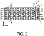
- FIG. 2 is a schematic cross-sectional view of the first composite material and the second composite material.
- the first composite material 12 is a composite material including reinforcing fibers 22 and a resin 24, and, in other words, is a composite material having the reinforcing fibers 22 impregnated with the resin 24.
- the reinforcing fibers 22 are fibers having a higher strength than the resin 24.
- the reinforcing fibers 22 are carbon fibers (Carbon Fibers) that are a carbon material.
- the reinforcing fibers 22 are not limited to carbon fibers, and may be other fibers, e.g., plastic fibers, glass fibers, or metal fibers.
- the resin 24 is a thermoplastic resin that melts when heated to a predetermined temperature.
- thermoplastic resins that can be used as the resin 24 include polyether ether ketone (PEEK), polyether ketone ketone (PEKK), polyphenylene sulfide (PPS), and the like.
- PEEK polyether ether ketone
- PEKK polyether ketone ketone
- PPS polyphenylene sulfide
- CFRP carbon fiber reinforced thermo plastic
- the resin 24 is not limited to the thermoplastic resin, and may be, for example, a thermosetting resin.
- An epoxy resin may be used as the thermosetting resin, for example.
- the first composite material 12 is configured by laminating a plurality of composite material layers 20 along the direction Z.
- the composite material layer 20 is a layer in which a plurality of reinforcing fibers 22 are aligned in the layer of the resin 24 that is a base material.
- the composite material layers 20 can be said to be layers including the reinforcing fibers 22 and the resin 24 that covers the reinforcing fibers 22.
- a thickness D1 of the composite material layer 20 along the direction Z is from 0.01 mm to 1 mm but is not limited thereto.
- the reinforcing fibers 22 are aligned in the direction X in each of the composite material layers 20.
- the plurality of reinforcing fibers 22 are aligned extending in the direction Y in the resin 24, which is the base material.
- the first composite material 12 is a unidirectional material, in other words, a UD material.
- the reinforcing fibers 22 are not limited to extending in the direction Y.
- the reinforcing fibers 22 are aligned extending in the same direction but the alignment extending direction of the reinforcing fibers 22 may be different for each of the composite material layers 20.
- the alignment extending direction of the reinforcing fibers 22 need not necessarily be one direction only, and alignment extending directions of the reinforcing fibers 22 may be oriented in a plurality of directions.
- the reinforcing fibers 22 aligned extending in mutually different directions (for example, the X direction and the Y direction) may be woven into one another in the composite material layers 20.
- the composite material layers 20 may be cross members.
- the second composite material 14 is a laminate body in which the composite material layers 20 are laminated in the direction Z, and is a composite material having the reinforcing fibers 22 impregnated with the resin 24.
- the second composite material 14 has the same structure as the first composite material 12.
- the second composite material 14 may have a different structure from the first composite material 12, as represented by the alignment extending direction of the reinforcing fibers 22 being different from that of the first composite material 12.
- the first composite material 12 and the second composite material 14 are bonded to each other. Since the first composite material 12 and the second composite material 14 are bonded by both the resin 24 in the first composite material 12 and the resin 24 in the second composite material 14, which are mixed together, there is no boundary between the first composite material 12 and the second composite material 14.
- the first composite material 12 may be provided with pins 18 between the composite material layers 20.
- the pins 18 are provided in alignment extending in the direction Z from the resin 24 of one of the laminated composite material layers 20, to the resin 24 of another one of the laminated composite material layers 20.
- the pin 18 is a member formed by providing a resin layer of the same material as that of the resin 24 around fibers of the same material as that of the reinforcing fibers 22.
- the pins 18 are disposed so as to penetrate through the composite material layers 20 when the composite material layers 20 are laminated together. During thermoforming, which will be described below, the resin layer of the pin 18 melts, hence, the fibers remain.
- the resin of the pins 18 may be a thermosetting resin. In this case, since the entirety of each of the pins 18 is cured during thermoforming, the interlayer strength between the composite material layers 20 can be enhanced. Further, each of the pins 18 is more preferably coated with an adhesive on a surface thereof. As a result, adhesion to the composite material layers 20 is enhanced.
- the material of the pins 18 is not limited to this example, and may be any material. Further, the pins 18 may also be provided between the second composite materials 14.
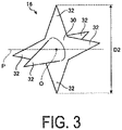
- FIG. 3 is a schematic perspective view of the protruding member according to the present embodiment.
- the protruding member 16 is a member having a plurality of protrusions 32.
- the protrusions 32 protrude in different directions.
- the protruding member 16 can be said to be a protruding member in which the protrusions 32 do not all extend in the same direction, and has the protrusions 32 extending in directions mutually different from the other protrusions 32. More specifically, in the protruding member 16, the plurality of protrusions 32 extend radially in mutually different directions, from an outer peripheral surface of a base material portion 30.
- a plane passing through a center O of the protruding member 16 is denoted as a plane P.
- the protruding member 16 includes, at least, the protrusion 32 that extends to one side in a direction perpendicular to the plane P, and the protrusion 32 that extends to another side in the direction perpendicular to the plane P.
- the protrusion 32 of the protruding member 16 extending to the one side can be inserted into the first composite material 12 and the protrusion 32 of the protruding member 16 extending to the other side can be inserted into the second composite material 14.
- the protruding member 16 may have two of the protrusions 32 but in this case, the protruding directions of the protrusions 32 are not aligned in a straight line, and the protruding directions of the protrusions 32 form an inclined hook shape therebetween.
- the protrusions 32 each has a tip of a pointed cone shape but the shape is not limited thereto.
- the protruding member 16 need not necessarily be provided with the base material portion 30, as long as the protruding member 16 includes the plurality of protrusions 32.
- the shape of the protruding member 16 is not limited to a shape in which the protrusions 32 protrude from the base material portion 30.
- the protruding member 16 may be formed by combining the plurality of protrusions 32 that are, for example, needle-shaped and extend in predetermined directions, without including the base material portion 30. Further, the protruding member 16 may have a shape in which the protrusions 32 have other protrusions 32 protruding therefrom.
- a particle size D2 of the protruding member 16 is preferably from 0.01 mm to 2 mm.
- the particle size D2 of the protrusion 32 is preferably from 0.1 to 2 times the thickness D1 of the composite material layer 20.
- the particle size D2 of the protruding member 16 is not limited to the length described above, and may be any length.
- the particle size D2 of the protruding member 16 is the longest outer diameter out of outer diameters of the protruding member 16.
- the particle size D2 is the longest distance among distances from the tip of one of the protrusions 32 to the tip of another of the protrusions 32 through the center of the protruding member 16.
- the particle size D2 may be, for example, a particle size determined based on a particle size distribution, which is determined by a laser diffraction/scattering method.
- the particle size D2 may be an average value of particle sizes (equivalent circle diameter) of all of the protruding members 16 determined by the laser diffraction/scattering method.
- the determination of the particle size D2 is not limited to this, and the particle size D2 may be obtained by other methods.
- the protruding member 16 having such a shape is provided from the interior of the first composite material 12 to the interior of the second composite material 14. More specifically, while some of the protrusions 32 of the protruding member 16 are introduced into the first composite material 12, the other protrusions 32 of the protruding member 16 are introduced into the second composite material 14 Accordingly, it can be said that the protruding member 16 is configured to couple (physically fasten) the first composite material 12 and the second composite material 14 to each other. Further, the plurality of protruding members 16 are provided in a dispersed manner along the direction X and the direction Y.
- the plurality of protruding members 16 are preferably provided uniformly in the surfaces of the first composite material 12 and the second composite material 14. Note that it is sufficient that at least some of the protruding members 16 be provided from the interior of the first composite material 12 to the interior of the second composite 14, and not all of the protruding members 16 need necessarily be provided from the interior of the first composite material 12 to the interior of the second composite 14. Further, in the example illustrated in FIG. 1 , the plurality of protruding members 16 are not provided along the direction Z but the plurality of protruding members 16 may be provided along the direction Z.
- the protruding members 16 are positioned in a region near a bonding surface between the first composite material 12 and the second composite material 14, and are not positioned in regions deep inside the first composite material 12 and the second composite 14. Specifically, a location on the surface of the first composite material 12 on the side of bonding with the second composite material 14 is denoted as a region 12S, and a location on the opposite side of the region 12S from the second composite material 14 is denoted as a region 12T. In this case, the protruding members 16 are positioned in the region 12S but are not positioned in the region 12T.
- the thickness of the region 12S along the direction Z is denoted as a thickness D3, and the thickness of the first composite material 12 along the direction Z is denoted as a thickness D4.
- the thickness D3 is preferably from 0.001 to 1 times the thickness D4.
- a location on the surface of the second composite material 14 on the side of bonding with the first composite material 12 is denoted as a region 14S
- a location on the opposite side of the region 14S from the first composite material 12 is denoted as a region 14T.
- the protruding members 16 are positioned in the region 14S, and more specifically, from the region 12S to the region 14S but are not positioned in the region 14T.
- the thickness of the region 14S along the direction Z is denoted as a thickness D5
- the thickness of the second composite material 14 along the direction Z is denoted as a thickness D6.
- the thickness D5 is preferably from 0.001 to 1 times the thickness D6.
- the protruding member 16 is formed of a composite material having reinforcing fibers 44 impregnated with a resin 42a.
- the reinforcing fibers 44 of the protruding member 16 are the same carbon fibers as the reinforcing fibers 22 of the first composite 12 but may also be formed of other materials, such as plastic fibers, glass fibers, or metal fibers.
- the resin 42a of the protruding member 16 is also a thermoplastic resin of the same material as that of the resin 24 of the first composite 12 but may have a different material from that of the resin 24 or may be a thermosetting resin.
- the protruding member 16 is a member in which the reinforcing fibers 44 are provided and the reinforcing fibers 44 are covered by the resin 42a.
- the protruding member 16 is not limited to being the composite material having the reinforcing fibers 44 impregnated with the resin 42a.
- the protruding member 16 may be configured of a material having higher temperature characteristics than the resin 24, and a high affinity with the resin 24.
- the high temperature characteristics include, for example, a higher fusing point than that of the resin 24, and the like.
- the material having the high affinity with the resin 24 refers to a material that easily bonds with the resin 24. Examples of this type of material of the protruding member 16 include a polybenzimidazole (trade name Poly Benz Imnidazol; PBI) resin, and a polyether ketone ether ketone ketone (PEKEKK)resin.
- FIG. 4 is a diagram illustrating a method for manufacturing the protruding member according to the present embodiment.
- a resin 42 and the reinforcing fibers 44 are fed into a container 40 as raw materials (step S10).
- the resin 42 is a thermoplastic resin of the same material as that of the resin 24, and is in a cured state.
- a plurality of pieces of the resin 42 are fed into the container 40.
- a plurality of the reinforcing fibers 44 of a predetermined length are fed into the container 40.
- the reinforcing fibers 44 are fed into the container 40 as chopped fibers. Once the small pieces of resin 42 and the chopped reinforcing fibers 44 are fed into the container 40, the resin 42 and reinforcing fibers 44 in the container 40 are stirred so that the reinforcing fibers 44 are uniformly dispersed in the container 40. As a result, the reinforcing fibers 44 are oriented in various directions.
- the resin 42 in the container 40 is heated thereby melting the resin 42 (step S12).
- the container 40 as a whole is heated from the outside of the container 40, and the resin 42 is heated to a temperature higher than or equal to the melting point of the resin 42.
- a pressure inside the container 40 is maintained at a predetermined pressure.
- the predetermined pressure in this case is, for example, from -1 MPa to 5 MPa, that is, the pressure is held at a relatively low pressure.
- the resin 42 melts, and the melted resin 42 fills the gaps between the pieces of resin 42 and the gaps between the pieces of resin 42 and the reinforcing fibers 44. Further, the reinforcing fibers 44 are impregnated with the melted resin 42.
- the heating is stopped and the resin 42 is cooled to the melting point or lower, to produce an intermediate material 16A.
- the pressure in the container 40 is maintained at the predetermined pressure.
- the resin 42 is cured to form the resin 42a.
- a plurality of empty holes 46 are created inside the resin 42a that is produced by the cooling.
- the intermediate material 16A produced by the cooling of the resin 42 is a member that includes the resin 42a, the reinforcing fibers 44, and the empty holes 46.
- the intermediate material 16A is a porous composite in which the plurality of reinforcing fibers 44 extending in mutually different directions are dispersed within a layer of the cured resin 42a, and in which the plurality of empty holes 46 are provided within the layer of resin 42a.
- the intermediate material 16A is removed from the container 40 (step S14).
- the removed intermediate material 16A is then broken into pieces to produce the plurality of protruding members 16 (step S16).
- Receiving an impact from outside, the intermediate material 16A is broken into pieces at the empty holes 46.
- the pieces of the broken intermediate material 16A respectively become the protruding members 16.
- each of the protruding members 16, which are the pieces formed by the breaking is shaped to have the plurality of protrusions 32.
- each of the protrusions 32 is formed by the reinforcing fibers 44 covered with the resin 42a.
- the protruding members 16 may differ in shape from each other as long as the protruding member 16 is the member having the plurality of protrusions 32. Note that, in the protrusion 32, at least some of the reinforcing fibers 44 may be exposed, without being covered by the resin 42a.
- the protruding member 16 is manufactured as described above. However, the method for manufacturing the protruding member 16 is not limited to this, and may be any method other than this.
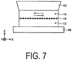
- FIG. 5 is an explanatory diagram illustrating a method for bonding the first composite material and the second composite material.
- the resin 24 is the thermoplastic resin
- the first composite material 12 and second composite material 14 prior to molding are in a cured state.
- the thermosetting resin is used as the resin 24, the first composite material 12 and second composite material 14 that are prepared prior to molding are in a prepreg state prior to curing of the resin 24.
- the first composite material 12 is placed on a base portion 60, and the protruding members 16 are placed on a surface 12A of the first composite material 12 (step S20; a protruding member placement step). More specifically, a back surface 12B of the first composite material 12 is brought into contact with the base portion 60, hence, the first composite material 12 is placed on the base portion 60.
- the surface 12A is a surface on one side of the first composite material 12 along the direction Z
- the back surface 12B is a surface on the other side of the first composite material 12 along the direction Z.
- a protruding member layer 15 is formed on the surface 12A of the first composite material 12 on the base portion 60.
- the protruding member layer 15 is a layer having the plurality of protruding members 16 provided inside a resin layer 17.
- the resin layer 17 is a layer of resin and is, for example, the same material as that of the resin 24 of the first composite material 12.
- the protruding member layer 15 has therein the protruding members 16 dispersed in the resin layer 17. Therefore, by forming the protruding member layer 15 on the surface 12A of the first composite material 12, the plurality of protruding members 16 are placed on the surface 12A of the first composite material 12.
- the protruding member layer 15 is in a cured state but may be a paste-like layer in which a pre-cured thermosetting resin is used as the resin layer 17, for example.
- the thickness of the protruding member layer 15 in the direction Z is thinner than the thickness of the first composite material 12 in the direction Z.
- the protruding members 16 are preferably placed such that the protrusions 32 protrude in the direction Z.
- the protrusions 32 of the protruding members 16 can be caused to be arranged along the direction Z by applying an electric current to the protruding member layer 15 along the direction X.
- the protruding member layer 15 need not necessarily be formed, and, for example, the plurality of protruding members 16 may be placed on the surface 12A of the first composite material 12 on the base 60.
- the second composite material 14 is placed at a location, where the protruding members 16 of the surface 12A of the first composite material 12 are placed (step S22; a second composite material placement step). More specifically, the second composite material 14 is placed on a surface 15B of the protruding member layer 15, which is on an opposite side to a surface 15A on the first composite material 12 side. In other words, a surface 14A of the second composite material 14 is brought into contact with the surface 15B of the protruding member layer 15. As a result, the first composite material 12 and the second composite material 14 are laminated with each other, with the protruding member layer 15 (the protruding members 16) interposed therebetween.
- the surface 14A is a surface on the other side of the second composite material 14 along the direction Z and the back surface 14B is a surface on one side of the second composite material 14 along the direction Z.
- the protruding members 16 are positioned between the first composite material 12 and the second composite 14, and have not entered the interior of the first composite material 12 and the interior of the second composite 14.
- the protruding members 16 are introduced into the first composite material 12 and the second composite material 14, whereby the first composite material 12 and the second composite material 14 are brought into contact with each other (step S24; an introduction step). More specifically, the resin 24 of the first composite material 12 and the resin 24 of the second composite material 14 are heated to a temperature higher than or equal to the melting point of the resin 24, whereby the resin 24 is caused to melt.
- the protruding members 16 enter the interior of the first composite material 12 and the interior of the second composite 14 as a result of being pressed by the head portion 62. More specifically, the resin layer 17 of the protruding member layer 15 also melts and mixes with the resin 24 of the first composite material 12 and the second composite material 14. Then, the protruding members 16 enter into the layer of the resin 24 of the first composite material 12 and the second composite material 14 as a result of being pressed by the head portion 62. As a result, the first composite material 12 and the second composite material 14 are brought into contact and fuse with each other. Then, the protruding members 16 are arranged from the interior of the first composite material 12 to the interior of the second composite material 14.
- the temperature of the protruding members 16 may be maintained to be lower than the temperature of the first composite material 12 and the second composite material 14, by heating the first composite material 12 and the second composite material 14 from outside (from the base portion 60 side and the head portion 62 side, for example).
- an electromagnetic field heating element may be provided inside the resin layer 17 or inside the first composite material 12 and the second composite material 14.
- the electromagnetic field heating element is a substance that generates heat when an electromagnetic field is applied. By applying the electromagnetic field to the electromagnetic heating element to generate heat, the first composite material 12 and the second composite material 14 that are in contact with each other can easily be caused to fuse with each other.
- the first composite material 12, the second composite material 14, the protruding members 16, and the resin layer 17 may have resins having mutually different melting points.
- the melting point of the resin of the protruding members 16 is set to be higher than the melting point of the resin of the first composite material 12, the second composite material 14, and the resin layer 17.
- members other than the protruding members 16 can be melted, whereby the protruding members 16 can easily be caused to penetrate the first composite material 12 and the second composite material 14.
- the resin of the protruding members 16 can be melted, and the resin can be integrated with other resins.
- a resin for example, PEEK resin
- a resin can have various melting points by adjusting components thereof.
- thermosetting resins when the resins of the first composite material 12, the second composite material 14, and the resin layer 17 are the thermosetting resins, after the protruding members 16 penetrate the first composite material 12 and the second composite material 14 as a result of being pressed, these thermosetting resins are cured by heating. In this way, the thermoplastic resin of the protruding members 16 and the thermosetting resins can be easily mixed together.
- step S26 a bonding step. More specifically, by cooling the resin 24 of the first composite material 12 and the resin 24 of the second composite 14, the first composite material 12 and the second composite 14 are bonded in a state in which the protruding members 16 are introduced therein. In this way, the manufacturing of the composite material 10 illustrated in FIG. 1 is completed.
- step S24 the first composite material 12, the protruding member layer 15, and the second composite material 14 are pressed by the head 62 without heating the resin 24. Due to this pressing, the protruding members 16 enter the interior of the first composite material 12 prior to being cured and the interior of the second composite material 14 prior to being cured. Then, in step S26, the resin 24 of the first composite material 12 and the resin 24 of the second composite material 14 are heated and cured, and the first composite material 12 and the second composite 14 are thus bonded in a state in which the protruding members 16 are introduced therein.
- the first composite material 12 and the second composite material 14 are, from an initial state prior to molding, in a state of having the reinforcing fibers 22 impregnated with the resin 24.
- the first composite material 12 and the second composite 14 need not necessarily include the resin 24, and may include only the reinforcing fibers 22.
- the first composite material 12 and the second composite material 14 that do not include the resin 24 are laminated, with the protruding member layer 15 interposed therebetween.
- step S24 the bonding step
- step S26 the bonding step
- the composite material 10 includes the first composite material 12 (the first composite material layer), the second composite material 14 (the second composite material layer), and the plurality of protruding members 16.
- the first composite material 12 is the layer of composite material having the reinforcing fibers 22 impregnated with the resin 24.
- the second composite material 14 is the layer of composite material bonded to the first composite material 12 and having the reinforcing fibers 22 impregnated with the resin 24.
- the protruding members 16 are provided from the interior of the first composite material 12 to the interior of the second composite material 14. Each of the protruding members 16 is provided with the plurality of protrusions 32 protruding in mutually different directions.
- the composite material 10 is formed such that the first composite material 12 and the second composite material 14 are bonded to each other and, in addition, the protruding members 16 are provided from the interior of the first composite material 12 to the interior of the second composite 14.
- the protruding members 16 physically fasten the first composite material 12 and the second composite 14.
- each of the protruding members 16 includes the plurality of protrusions 32 extending in mutually different directions. Therefore, the protruding members 16 are less likely to fall out from the first composite material 12 and the second composite material 14. Therefore, the composite material 10 can suppress delamination between the first composite material 12 and the second composite material 14.
- the method for bonding a composite material is a method for bonding the first composite material 12 including the reinforcing fibers 22 and the second composite material 14 including the reinforcing fibers 22 by impregnating the first composite material 12 and the second composite material 14 with the resin 24.
- This bonding method includes the protruding member placement step, the second composite material placement step, the introduction step, and the bonding step.
- the protruding member placement step the plurality of protruding members 16 are placed on the surface 12A of the first composite material 12.
- Each of the protruding members 16 includes the plurality of protrusions 32 protruding in mutually different directions.
- the second composite material 14 is placed at a location at which the protruding members 16 on the surface 12A of the first composite material 12 are placed. Then, in the introduction step, the first composite material 12 and the second composite 14 are brought into contact with each other while the protruding members 16 are introduced into the interior of the first composite material 12 and the interior of the second composite material 14. Then, in the bonding step, the first composite material 12 and the second composite material 14 are bonded together in a state where the protruding members 16 are introduced therein, by curing the resin 24 with which the first composite material 12 and the second composite material 14 are impregnated.
- the first composite material 12 and the second composite material 14 are bonded together in a state where the protruding members 16 are introduced therein. Accordingly, the first composite material 12 and the second composite material 14 can be bonded while being physically fastened together by the protruding members 16. Furthermore, each of the protruding members 16 includes the plurality of protrusions 32 extending in mutually different directions. Therefore, the protruding members 16 are less likely to fall out from the first composite material 12 and the second composite material 14. As a result, according to this bonding method, delamination between the first composite material 12 and the second composite material 14 can be suppressed.
- the resin 24 with which the composite material 12 and the second composite material 14 are impregnated is a thermoplastic resin. Then, in the introduction step, the resin 24, with which the first composite material 12 and the second composite material 14 are impregnated, is heated and melted, whereby the protruding members 16 are introduced into the first composite material 12 and the second composite material 14. Further, in the bonding step, the resin 24, with which the first composite material 12 and the second composite material 14 are impregnated, is cured by cooling. This bonding method allows the resin 24, which is a thermoplastic resin, to be heated and melted, thereby making the resin 24 soft, and allowing the protruding members 16 to be introduced into the layers of the resin 24 of the first composite material 12 and the second composite material 14.
- the first composite material 12 and the second composite material 14 are cured and bonded to each other in the state in which the protruding members 16 are introduced therein.
- this bonding method in the composite material in which the thermoplastic resin is used, delamination between the first composite material 12 and the second composite material 14 can be favorably suppressed.
- the protruding member layer 15 that includes the plurality of protruding members 16 in the resin is formed on the surface 12A of the first composite material 12.
- the protruding members 16 can be appropriately formed on the surface 12A of the first composite 12, and the protruding members 16 can be appropriately introduced in the interiors of the first composite material 12 and the second composite material 14.
- the protruding members 16 are formed of the composite material having the reinforcing fibers 44 impregnated with the resin 42a. According to this bonding method, by using as the protruding members 16 the composite material having the reinforcing fibers 44 impregnated with the resin 42a, delamination between the first composite 12 and the second composite 14 can be favorably suppressed while improving adhesion of the protruding members 16 to the first composite material 12 and the second composite material 14.
- the protruding members 16 are formed by crushing the porous intermediate material 16A.
- the intermediate material 16A is formed by heating and then cooling raw materials, which include the plurality of reinforcing fibers 44 of the predetermined length and the resin 42, under a predetermined pressure.
- FIG. 6 is a diagram illustrating another example of a bonded state of the first composite material and the second composite material.
- the first composite material 12 and the second composite material 14 are bonded together by the entire surfaces thereof but as illustrated in FIG. 6 , part of the surfaces may be bonded together.
- the protruding members 16 may be provided only on the part of the surfaces to be bonded.
- the protruding members 16 are provided evenly across the entire area of the surfaces to be bonded but the present invention is not limited to this.
- a larger number of the protruding members 16 may be placed at end portions of the surfaces to be bonded, and a smaller number of the protruding members 16 may be placed at parts other than the end portions of the surfaces to be bonded. In this way, a bonding force at the end portions, where stress increases, can be enhanced, and delamination can be favorably suppressed.
- a larger number of the protruding members 16 may be placed at a center portion of the surfaces to be bonded, and a smaller number of the protruding members 16 may be placed at the end portions of the surfaces to be bonded. While the bonding force tends to be low at the center portion of the bonding surfaces, the bonding force at the center portion can be favorably enhanced by placing a larger number of the protruding members 16 thereat.
- FIG. 7 is a diagram illustrating another example of a bonding method for the first composite material and the second composite material.
- the introduction step for introducing the protruding members 16 in the interiors of the first composite material 12 and the second composite material 14 may be performed as illustrated in FIG. 7 . That is, as illustrated in FIG. 7 , the second composite material 14 is caused to move in a reciprocating manner with respect to the first composite material 12, in a direction orthogonal to the lamination direction (the direction Z), that is, in a direction along the surface. This movement causes the protruding members 16 including the plurality of protrusions 32 to be rubbed whereby heat is generated, and the resins 24 of the first composite material 12 and the second composite 14 can be melted quicker. In other words, vibration fusion may be performed in the introduction step.
Landscapes
- Engineering & Computer Science (AREA)
- Mechanical Engineering (AREA)
- Chemical & Material Sciences (AREA)
- Materials Engineering (AREA)
- Composite Materials (AREA)
- Polymers & Plastics (AREA)
- Chemical Kinetics & Catalysis (AREA)
- Medicinal Chemistry (AREA)
- Health & Medical Sciences (AREA)
- Organic Chemistry (AREA)
- Manufacturing & Machinery (AREA)
- Inorganic Chemistry (AREA)
- Laminated Bodies (AREA)
- Lining Or Joining Of Plastics Or The Like (AREA)
- Reinforced Plastic Materials (AREA)
- Moulding By Coating Moulds (AREA)
Claims (5)
- Procédé pour le collage d'un premier matériau composite (12) qui contient des fibres de renfort (22) et est capable d'être imprégné d'une résine et d'un deuxième matériau composite (14) qui contient des fibres de renfort (22) et qui est capable d'être imprégné d'une résine, le procédé comprenant :une étape de placement d'éléments en saillie (S20) pour placer, sur une surface (12A) du premier matériau composite (12), une pluralité d'éléments en saillie (16) comportant chacun une pluralité de saillies (32) faisant saillie dans des directions mutuellement différentes ;une étape de placement de deuxième matériau composite (S22) pour placer le deuxième matériau composite (14) à un emplacement, où les éléments en saillie (16) sont placés, de la surface (12A) du premier matériau composite (12) ;une étape d'introduction (S24) pour introduire les éléments en saillie (16) dans l'intérieur du premier matériau composite (12) et l'intérieur du deuxième matériau composite (14) pour mettre le premier matériau composite (12) et le deuxième matériau composite (14) en contact avec l'autre ; etune étape de collage (S26) pour faire durcir la résine (24) dont le premier matériau composite (12) et le deuxième matériau composite (14) sont chacun imprégnés dans un état où les éléments en saillie (16) sont introduits dans les intérieurs pour coller le premier matériau composite (12) et le deuxième matériau composite (14),dans lequel l'élément en saillie (16) est constitué d'un matériau composite ayant des fibres de renfort (44) imprégnées d'une résine (42), et est formé par chauffage, sous une pression prédéterminée, d'un matériau brut comportant une pluralité de fibres de renfort (44) d'une longueur prédéterminée et une résine (42), puis refroidissement du matériau brut pour former un matériau intermédiaire (16A) poreux, et écrasement du matériau intermédiaire (16A).
- Procédé selon la revendication 1, dans lequella résine (24) dont le premier matériau composite (12) et le deuxième matériau composite (14) sont chacun imprégnés est une résine thermoplastique,l'étape d'introduction (S24) comporte le chauffage et la fusion de la résine (24) dont le premier matériau composite (12) et le deuxième matériau composite (14) sont chacun imprégnés pour introduire les éléments en saillie (16) dans les intérieurs du premier matériau composite (12) et du deuxième matériau composite (14), etl'étape de collage (S26) comporte le refroidissement de la résine (24) dont le premier matériau composite (12) et le deuxième matériau composite (14) sont chacun imprégnés pour faire durcir la résine (24).
- Procédé selon la revendication 1, dans lequel l'étape de placement d'éléments en saillie (S20) comporte la formation, sur une surface (12A) du premier matériau composite (12), d'une couche d'éléments en saillie (15) dans laquelle les éléments en saillie (16) sont compris dans une résine (42).
- Procédé selon la revendication 1, dans lequel dans l'étape d'introduction (S24), le deuxième matériau composite (14) est amené à se déplacer d'une manière alternative par rapport au premier matériau composite (12), dans une direction orthogonale à une direction de stratification comme une direction le long de la surface.
- Procédé selon la revendication 1, dans lequel le premier matériau composite (12) et le deuxième matériau composite (14) ne comportent pas la résine (24), et comportent uniquement les fibres de renfort (22), jusqu'à l'étape de collage (S26).
Applications Claiming Priority (2)
| Application Number | Priority Date | Filing Date | Title |
|---|---|---|---|
| JP2017235329A JP6964502B2 (ja) | 2017-12-07 | 2017-12-07 | 複合材料の接合方法 |
| PCT/JP2018/039477 WO2019111571A1 (fr) | 2017-12-07 | 2018-10-24 | Procédé pour le collage d'un matériau composite et matériau composite |
Publications (3)
| Publication Number | Publication Date |
|---|---|
| EP3705271A1 EP3705271A1 (fr) | 2020-09-09 |
| EP3705271A4 EP3705271A4 (fr) | 2021-02-24 |
| EP3705271B1 true EP3705271B1 (fr) | 2022-04-06 |
Family
ID=66751460
Family Applications (1)
| Application Number | Title | Priority Date | Filing Date |
|---|---|---|---|
| EP18885792.4A Active EP3705271B1 (fr) | 2017-12-07 | 2018-10-24 | Procédé pour le collage d'un matériau composite |
Country Status (5)
| Country | Link |
|---|---|
| US (1) | US20210221077A1 (fr) |
| EP (1) | EP3705271B1 (fr) |
| JP (1) | JP6964502B2 (fr) |
| BR (1) | BR112020011237A2 (fr) |
| WO (1) | WO2019111571A1 (fr) |
Families Citing this family (4)
| Publication number | Priority date | Publication date | Assignee | Title |
|---|---|---|---|---|
| JP7511354B2 (ja) * | 2020-02-12 | 2024-07-05 | 三菱重工業株式会社 | 複合材料構造体 |
| US20230294128A1 (en) * | 2021-01-21 | 2023-09-21 | Mitsubishi Heavy Industries, Ltd. | Pre-coating processing method and pre-coating processing system for fiber-reinforced thermoplastic member |
| JP2024064762A (ja) * | 2022-10-28 | 2024-05-14 | 三菱重工業株式会社 | 接着方法及び接着構造体 |
| WO2025249142A1 (fr) * | 2024-05-27 | 2025-12-04 | 日機装株式会社 | Corps de raccordement et procédé de fabrication d'un corps de raccordement |
Family Cites Families (7)
| Publication number | Priority date | Publication date | Assignee | Title |
|---|---|---|---|---|
| JPH03297629A (ja) * | 1990-04-18 | 1991-12-27 | Mitsubishi Heavy Ind Ltd | 熱可塑複合材構造物の製造方法 |
| JP2007307778A (ja) * | 2006-05-18 | 2007-11-29 | Toyota Motor Corp | 繊維強化樹脂よりなる積層構造体および該積層構造体の製造方法 |
| KR100932302B1 (ko) | 2007-09-17 | 2009-12-16 | 한국항공우주연구원 | 핀을 박아 성능을 보강한 복합재 적층 구조물, 상기 복합재적층 구조물 제조 방법, 장치 및 상기 장치 제작 방법 |
| US10160172B2 (en) * | 2014-08-06 | 2018-12-25 | GM Global Technology Operations LLC | Mechanical interlocking realized through induction heating for polymeric composite repair |
| EP3088121B1 (fr) * | 2015-04-29 | 2018-07-18 | Airbus Defence and Space GmbH | Composant métallique ayant au moins une section de liaison structurée multidimensionnelle et son procédé de production |
| JP2016215499A (ja) * | 2015-05-20 | 2016-12-22 | 国立大学法人徳島大学 | 繊維強化樹脂成型体及びその製造方法並びに固定具 |
| CN107735242B (zh) * | 2015-07-06 | 2020-04-14 | 伍德韦尔丁公司 | 将物体结合在一起 |
-
2017
- 2017-12-07 JP JP2017235329A patent/JP6964502B2/ja active Active
-
2018
- 2018-10-24 BR BR112020011237-2A patent/BR112020011237A2/pt not_active Application Discontinuation
- 2018-10-24 WO PCT/JP2018/039477 patent/WO2019111571A1/fr not_active Ceased
- 2018-10-24 EP EP18885792.4A patent/EP3705271B1/fr active Active
- 2018-10-24 US US16/768,990 patent/US20210221077A1/en not_active Abandoned
Also Published As
| Publication number | Publication date |
|---|---|
| WO2019111571A1 (fr) | 2019-06-13 |
| JP6964502B2 (ja) | 2021-11-10 |
| EP3705271A4 (fr) | 2021-02-24 |
| JP2019098704A (ja) | 2019-06-24 |
| EP3705271A1 (fr) | 2020-09-09 |
| US20210221077A1 (en) | 2021-07-22 |
| BR112020011237A2 (pt) | 2020-11-24 |
Similar Documents
| Publication | Publication Date | Title |
|---|---|---|
| EP3705271B1 (fr) | Procédé pour le collage d'un matériau composite | |
| CN101730618B (zh) | 热塑性材料与纤维复合材料的接合方法 | |
| EP2714372B1 (fr) | Procede pour fixer un polymere thermoplastique a un composant de polymere thermodurcissable | |
| JP6630480B2 (ja) | 一時的に縫合されたプリフォームを用いた複合積層体の製造 | |
| US8790487B2 (en) | Method of fabricating a part out of reinforced composite material, and a method of repairing such a part | |
| EP1406757B1 (fr) | Procede de fabrication de joints de structure en utilisant des preformes textiles tissees tridimensionnelles impregnees d'adhesif | |
| US20150314501A1 (en) | Method and system for homogenous thermoplastic seat back assembly | |
| JP6239347B2 (ja) | 複合材接合システムおよび方法 | |
| US11458719B2 (en) | Method for joining by bonding of parts, in particular composite parts having fibrous reinforcement | |
| US20160176085A1 (en) | Method and system for producing composite structures | |
| CN109071838A (zh) | 纤维增强树脂中间材料、纤维增强树脂成形体以及纤维增强树脂中间材料的制造方法 | |
| JP6778147B2 (ja) | 複合材料翼及び複合材料翼の製造方法 | |
| EP3867046A1 (fr) | Procédé et appareil pour le moulage composite de nervure et de nervure et feuille | |
| EP3698957B1 (fr) | Timbre de réparation, procédé de moulage de timbre de réparation, procédé de réparation de matériau composite, et gabarit de moulage | |
| EP4289606A1 (fr) | Système d'application de pression semi-conformable et procédé d'assemblage de pièces composites | |
| US11090876B2 (en) | Assembly of sub-components by compression molding | |
| US11383460B2 (en) | Method for producing composite material | |
| JP2019111710A (ja) | 炭素繊維テープ材及びその積層シート基材 | |
| EP3737653B1 (fr) | Matériaux composites renforcés par des fibres ayant une résistance améliorée à la fatigue | |
| JP7051414B2 (ja) | 複合材料成形方法及び複合材料 | |
| EP2781345B1 (fr) | Procédé et système de production de structures composites | |
| WO2017187920A1 (fr) | Procédé d'assemblage d'éléments joints et élément joint |
Legal Events
| Date | Code | Title | Description |
|---|---|---|---|
| STAA | Information on the status of an ep patent application or granted ep patent |
Free format text: STATUS: THE INTERNATIONAL PUBLICATION HAS BEEN MADE |
|
| PUAI | Public reference made under article 153(3) epc to a published international application that has entered the european phase |
Free format text: ORIGINAL CODE: 0009012 |
|
| STAA | Information on the status of an ep patent application or granted ep patent |
Free format text: STATUS: REQUEST FOR EXAMINATION WAS MADE |
|
| 17P | Request for examination filed |
Effective date: 20200603 |
|
| AK | Designated contracting states |
Kind code of ref document: A1 Designated state(s): AL AT BE BG CH CY CZ DE DK EE ES FI FR GB GR HR HU IE IS IT LI LT LU LV MC MK MT NL NO PL PT RO RS SE SI SK SM TR |
|
| AX | Request for extension of the european patent |
Extension state: BA ME |
|
| A4 | Supplementary search report drawn up and despatched |
Effective date: 20210122 |
|
| RIC1 | Information provided on ipc code assigned before grant |
Ipc: B29C 65/48 20060101ALI20210118BHEP Ipc: B29C 65/56 20060101ALI20210118BHEP Ipc: B29C 65/02 20060101AFI20210118BHEP Ipc: B32B 5/28 20060101ALI20210118BHEP Ipc: B29C 65/50 20060101ALI20210118BHEP Ipc: B29C 65/06 20060101ALI20210118BHEP Ipc: B29C 65/36 20060101ALI20210118BHEP |
|
| DAV | Request for validation of the european patent (deleted) | ||
| DAX | Request for extension of the european patent (deleted) | ||
| STAA | Information on the status of an ep patent application or granted ep patent |
Free format text: STATUS: EXAMINATION IS IN PROGRESS |
|
| 17Q | First examination report despatched |
Effective date: 20210721 |
|
| REG | Reference to a national code |
Ref country code: DE Ref legal event code: R079 Ref document number: 602018033608 Country of ref document: DE Free format text: PREVIOUS MAIN CLASS: B29C0065560000 Ipc: B29C0065020000 |
|
| GRAP | Despatch of communication of intention to grant a patent |
Free format text: ORIGINAL CODE: EPIDOSNIGR1 |
|
| STAA | Information on the status of an ep patent application or granted ep patent |
Free format text: STATUS: GRANT OF PATENT IS INTENDED |
|
| RIC1 | Information provided on ipc code assigned before grant |
Ipc: B29C 70/88 20060101ALI20211013BHEP Ipc: B29C 70/86 20060101ALI20211013BHEP Ipc: B32B 5/28 20060101ALI20211013BHEP Ipc: B29C 65/56 20060101ALI20211013BHEP Ipc: B29C 65/50 20060101ALI20211013BHEP Ipc: B29C 65/48 20060101ALI20211013BHEP Ipc: B29C 65/36 20060101ALI20211013BHEP Ipc: B29C 65/06 20060101ALI20211013BHEP Ipc: B29C 65/02 20060101AFI20211013BHEP |
|
| INTG | Intention to grant announced |
Effective date: 20211026 |
|
| GRAS | Grant fee paid |
Free format text: ORIGINAL CODE: EPIDOSNIGR3 |
|
| GRAA | (expected) grant |
Free format text: ORIGINAL CODE: 0009210 |
|
| STAA | Information on the status of an ep patent application or granted ep patent |
Free format text: STATUS: THE PATENT HAS BEEN GRANTED |
|
| AK | Designated contracting states |
Kind code of ref document: B1 Designated state(s): AL AT BE BG CH CY CZ DE DK EE ES FI FR GB GR HR HU IE IS IT LI LT LU LV MC MK MT NL NO PL PT RO RS SE SI SK SM TR |
|
| REG | Reference to a national code |
Ref country code: GB Ref legal event code: FG4D |
|
| REG | Reference to a national code |
Ref country code: CH Ref legal event code: EP |
|
| REG | Reference to a national code |
Ref country code: AT Ref legal event code: REF Ref document number: 1480926 Country of ref document: AT Kind code of ref document: T Effective date: 20220415 |
|
| REG | Reference to a national code |
Ref country code: IE Ref legal event code: FG4D |
|
| REG | Reference to a national code |
Ref country code: DE Ref legal event code: R096 Ref document number: 602018033608 Country of ref document: DE |
|
| REG | Reference to a national code |
Ref country code: LT Ref legal event code: MG9D |
|
| REG | Reference to a national code |
Ref country code: NL Ref legal event code: MP Effective date: 20220406 |
|
| REG | Reference to a national code |
Ref country code: AT Ref legal event code: MK05 Ref document number: 1480926 Country of ref document: AT Kind code of ref document: T Effective date: 20220406 |
|
| PG25 | Lapsed in a contracting state [announced via postgrant information from national office to epo] |
Ref country code: NL Free format text: LAPSE BECAUSE OF FAILURE TO SUBMIT A TRANSLATION OF THE DESCRIPTION OR TO PAY THE FEE WITHIN THE PRESCRIBED TIME-LIMIT Effective date: 20220406 |
|
| PG25 | Lapsed in a contracting state [announced via postgrant information from national office to epo] |
Ref country code: SE Free format text: LAPSE BECAUSE OF FAILURE TO SUBMIT A TRANSLATION OF THE DESCRIPTION OR TO PAY THE FEE WITHIN THE PRESCRIBED TIME-LIMIT Effective date: 20220406 Ref country code: PT Free format text: LAPSE BECAUSE OF FAILURE TO SUBMIT A TRANSLATION OF THE DESCRIPTION OR TO PAY THE FEE WITHIN THE PRESCRIBED TIME-LIMIT Effective date: 20220808 Ref country code: NO Free format text: LAPSE BECAUSE OF FAILURE TO SUBMIT A TRANSLATION OF THE DESCRIPTION OR TO PAY THE FEE WITHIN THE PRESCRIBED TIME-LIMIT Effective date: 20220706 Ref country code: LT Free format text: LAPSE BECAUSE OF FAILURE TO SUBMIT A TRANSLATION OF THE DESCRIPTION OR TO PAY THE FEE WITHIN THE PRESCRIBED TIME-LIMIT Effective date: 20220406 Ref country code: HR Free format text: LAPSE BECAUSE OF FAILURE TO SUBMIT A TRANSLATION OF THE DESCRIPTION OR TO PAY THE FEE WITHIN THE PRESCRIBED TIME-LIMIT Effective date: 20220406 Ref country code: GR Free format text: LAPSE BECAUSE OF FAILURE TO SUBMIT A TRANSLATION OF THE DESCRIPTION OR TO PAY THE FEE WITHIN THE PRESCRIBED TIME-LIMIT Effective date: 20220707 Ref country code: FI Free format text: LAPSE BECAUSE OF FAILURE TO SUBMIT A TRANSLATION OF THE DESCRIPTION OR TO PAY THE FEE WITHIN THE PRESCRIBED TIME-LIMIT Effective date: 20220406 Ref country code: ES Free format text: LAPSE BECAUSE OF FAILURE TO SUBMIT A TRANSLATION OF THE DESCRIPTION OR TO PAY THE FEE WITHIN THE PRESCRIBED TIME-LIMIT Effective date: 20220406 Ref country code: BG Free format text: LAPSE BECAUSE OF FAILURE TO SUBMIT A TRANSLATION OF THE DESCRIPTION OR TO PAY THE FEE WITHIN THE PRESCRIBED TIME-LIMIT Effective date: 20220706 Ref country code: AT Free format text: LAPSE BECAUSE OF FAILURE TO SUBMIT A TRANSLATION OF THE DESCRIPTION OR TO PAY THE FEE WITHIN THE PRESCRIBED TIME-LIMIT Effective date: 20220406 |
|
| PG25 | Lapsed in a contracting state [announced via postgrant information from national office to epo] |
Ref country code: RS Free format text: LAPSE BECAUSE OF FAILURE TO SUBMIT A TRANSLATION OF THE DESCRIPTION OR TO PAY THE FEE WITHIN THE PRESCRIBED TIME-LIMIT Effective date: 20220406 Ref country code: PL Free format text: LAPSE BECAUSE OF FAILURE TO SUBMIT A TRANSLATION OF THE DESCRIPTION OR TO PAY THE FEE WITHIN THE PRESCRIBED TIME-LIMIT Effective date: 20220406 Ref country code: LV Free format text: LAPSE BECAUSE OF FAILURE TO SUBMIT A TRANSLATION OF THE DESCRIPTION OR TO PAY THE FEE WITHIN THE PRESCRIBED TIME-LIMIT Effective date: 20220406 Ref country code: IS Free format text: LAPSE BECAUSE OF FAILURE TO SUBMIT A TRANSLATION OF THE DESCRIPTION OR TO PAY THE FEE WITHIN THE PRESCRIBED TIME-LIMIT Effective date: 20220806 |
|
| REG | Reference to a national code |
Ref country code: DE Ref legal event code: R097 Ref document number: 602018033608 Country of ref document: DE |
|
| PG25 | Lapsed in a contracting state [announced via postgrant information from national office to epo] |
Ref country code: SM Free format text: LAPSE BECAUSE OF FAILURE TO SUBMIT A TRANSLATION OF THE DESCRIPTION OR TO PAY THE FEE WITHIN THE PRESCRIBED TIME-LIMIT Effective date: 20220406 Ref country code: SK Free format text: LAPSE BECAUSE OF FAILURE TO SUBMIT A TRANSLATION OF THE DESCRIPTION OR TO PAY THE FEE WITHIN THE PRESCRIBED TIME-LIMIT Effective date: 20220406 Ref country code: RO Free format text: LAPSE BECAUSE OF FAILURE TO SUBMIT A TRANSLATION OF THE DESCRIPTION OR TO PAY THE FEE WITHIN THE PRESCRIBED TIME-LIMIT Effective date: 20220406 Ref country code: EE Free format text: LAPSE BECAUSE OF FAILURE TO SUBMIT A TRANSLATION OF THE DESCRIPTION OR TO PAY THE FEE WITHIN THE PRESCRIBED TIME-LIMIT Effective date: 20220406 Ref country code: DK Free format text: LAPSE BECAUSE OF FAILURE TO SUBMIT A TRANSLATION OF THE DESCRIPTION OR TO PAY THE FEE WITHIN THE PRESCRIBED TIME-LIMIT Effective date: 20220406 Ref country code: CZ Free format text: LAPSE BECAUSE OF FAILURE TO SUBMIT A TRANSLATION OF THE DESCRIPTION OR TO PAY THE FEE WITHIN THE PRESCRIBED TIME-LIMIT Effective date: 20220406 |
|
| PLBE | No opposition filed within time limit |
Free format text: ORIGINAL CODE: 0009261 |
|
| STAA | Information on the status of an ep patent application or granted ep patent |
Free format text: STATUS: NO OPPOSITION FILED WITHIN TIME LIMIT |
|
| 26N | No opposition filed |
Effective date: 20230110 |
|
| PG25 | Lapsed in a contracting state [announced via postgrant information from national office to epo] |
Ref country code: AL Free format text: LAPSE BECAUSE OF FAILURE TO SUBMIT A TRANSLATION OF THE DESCRIPTION OR TO PAY THE FEE WITHIN THE PRESCRIBED TIME-LIMIT Effective date: 20220406 |
|
| PG25 | Lapsed in a contracting state [announced via postgrant information from national office to epo] |
Ref country code: SI Free format text: LAPSE BECAUSE OF FAILURE TO SUBMIT A TRANSLATION OF THE DESCRIPTION OR TO PAY THE FEE WITHIN THE PRESCRIBED TIME-LIMIT Effective date: 20220406 Ref country code: MC Free format text: LAPSE BECAUSE OF FAILURE TO SUBMIT A TRANSLATION OF THE DESCRIPTION OR TO PAY THE FEE WITHIN THE PRESCRIBED TIME-LIMIT Effective date: 20220406 |
|
| REG | Reference to a national code |
Ref country code: CH Ref legal event code: PL |
|
| REG | Reference to a national code |
Ref country code: BE Ref legal event code: MM Effective date: 20221031 |
|
| PG25 | Lapsed in a contracting state [announced via postgrant information from national office to epo] |
Ref country code: LU Free format text: LAPSE BECAUSE OF NON-PAYMENT OF DUE FEES Effective date: 20221024 |
|
| PG25 | Lapsed in a contracting state [announced via postgrant information from national office to epo] |
Ref country code: LI Free format text: LAPSE BECAUSE OF NON-PAYMENT OF DUE FEES Effective date: 20221031 Ref country code: CH Free format text: LAPSE BECAUSE OF NON-PAYMENT OF DUE FEES Effective date: 20221031 |
|
| PG25 | Lapsed in a contracting state [announced via postgrant information from national office to epo] |
Ref country code: BE Free format text: LAPSE BECAUSE OF NON-PAYMENT OF DUE FEES Effective date: 20221031 |
|
| PG25 | Lapsed in a contracting state [announced via postgrant information from national office to epo] |
Ref country code: IE Free format text: LAPSE BECAUSE OF NON-PAYMENT OF DUE FEES Effective date: 20221024 |
|
| PG25 | Lapsed in a contracting state [announced via postgrant information from national office to epo] |
Ref country code: IT Free format text: LAPSE BECAUSE OF FAILURE TO SUBMIT A TRANSLATION OF THE DESCRIPTION OR TO PAY THE FEE WITHIN THE PRESCRIBED TIME-LIMIT Effective date: 20220406 |
|
| PG25 | Lapsed in a contracting state [announced via postgrant information from national office to epo] |
Ref country code: CY Free format text: LAPSE BECAUSE OF FAILURE TO SUBMIT A TRANSLATION OF THE DESCRIPTION OR TO PAY THE FEE WITHIN THE PRESCRIBED TIME-LIMIT Effective date: 20220406 |
|
| PG25 | Lapsed in a contracting state [announced via postgrant information from national office to epo] |
Ref country code: MK Free format text: LAPSE BECAUSE OF FAILURE TO SUBMIT A TRANSLATION OF THE DESCRIPTION OR TO PAY THE FEE WITHIN THE PRESCRIBED TIME-LIMIT Effective date: 20220406 Ref country code: HU Free format text: LAPSE BECAUSE OF FAILURE TO SUBMIT A TRANSLATION OF THE DESCRIPTION OR TO PAY THE FEE WITHIN THE PRESCRIBED TIME-LIMIT; INVALID AB INITIO Effective date: 20181024 |
|
| PG25 | Lapsed in a contracting state [announced via postgrant information from national office to epo] |
Ref country code: MT Free format text: LAPSE BECAUSE OF FAILURE TO SUBMIT A TRANSLATION OF THE DESCRIPTION OR TO PAY THE FEE WITHIN THE PRESCRIBED TIME-LIMIT Effective date: 20220406 |
|
| PG25 | Lapsed in a contracting state [announced via postgrant information from national office to epo] |
Ref country code: BG Free format text: LAPSE BECAUSE OF FAILURE TO SUBMIT A TRANSLATION OF THE DESCRIPTION OR TO PAY THE FEE WITHIN THE PRESCRIBED TIME-LIMIT Effective date: 20220406 |
|
| PG25 | Lapsed in a contracting state [announced via postgrant information from national office to epo] |
Ref country code: BG Free format text: LAPSE BECAUSE OF FAILURE TO SUBMIT A TRANSLATION OF THE DESCRIPTION OR TO PAY THE FEE WITHIN THE PRESCRIBED TIME-LIMIT Effective date: 20220406 |
|
| PGFP | Annual fee paid to national office [announced via postgrant information from national office to epo] |
Ref country code: GB Payment date: 20250904 Year of fee payment: 8 |
|
| PGFP | Annual fee paid to national office [announced via postgrant information from national office to epo] |
Ref country code: FR Payment date: 20250908 Year of fee payment: 8 |
|
| PG25 | Lapsed in a contracting state [announced via postgrant information from national office to epo] |
Ref country code: TR Free format text: LAPSE BECAUSE OF FAILURE TO SUBMIT A TRANSLATION OF THE DESCRIPTION OR TO PAY THE FEE WITHIN THE PRESCRIBED TIME-LIMIT Effective date: 20220406 |
|
| PGFP | Annual fee paid to national office [announced via postgrant information from national office to epo] |
Ref country code: DE Payment date: 20250902 Year of fee payment: 8 |