EP3705254A1 - Production method of mold having recessed pattern in recessed step portion, and manufacturing method of pattern sheet - Google Patents
Production method of mold having recessed pattern in recessed step portion, and manufacturing method of pattern sheet Download PDFInfo
- Publication number
- EP3705254A1 EP3705254A1 EP20160513.6A EP20160513A EP3705254A1 EP 3705254 A1 EP3705254 A1 EP 3705254A1 EP 20160513 A EP20160513 A EP 20160513A EP 3705254 A1 EP3705254 A1 EP 3705254A1
- Authority
- EP
- European Patent Office
- Prior art keywords
- recessed
- pattern
- plate precursor
- step portion
- mold
- Prior art date
- Legal status (The legal status is an assumption and is not a legal conclusion. Google has not performed a legal analysis and makes no representation as to the accuracy of the status listed.)
- Granted
Links
Images









Classifications
-
- B—PERFORMING OPERATIONS; TRANSPORTING
- B29—WORKING OF PLASTICS; WORKING OF SUBSTANCES IN A PLASTIC STATE IN GENERAL
- B29C—SHAPING OR JOINING OF PLASTICS; SHAPING OF MATERIAL IN A PLASTIC STATE, NOT OTHERWISE PROVIDED FOR; AFTER-TREATMENT OF THE SHAPED PRODUCTS, e.g. REPAIRING
- B29C33/00—Moulds or cores; Details thereof or accessories therefor
- B29C33/38—Moulds or cores; Details thereof or accessories therefor characterised by the material or the manufacturing process
- B29C33/3842—Manufacturing moulds, e.g. shaping the mould surface by machining
- B29C33/3857—Manufacturing moulds, e.g. shaping the mould surface by machining by making impressions of one or more parts of models, e.g. shaped articles and including possible subsequent assembly of the parts
-
- A—HUMAN NECESSITIES
- A61—MEDICAL OR VETERINARY SCIENCE; HYGIENE
- A61M—DEVICES FOR INTRODUCING MEDIA INTO, OR ONTO, THE BODY; DEVICES FOR TRANSDUCING BODY MEDIA OR FOR TAKING MEDIA FROM THE BODY; DEVICES FOR PRODUCING OR ENDING SLEEP OR STUPOR
- A61M37/00—Other apparatus for introducing media into the body; Percutany, i.e. introducing medicines into the body by diffusion through the skin
- A61M37/0015—Other apparatus for introducing media into the body; Percutany, i.e. introducing medicines into the body by diffusion through the skin by using microneedles
-
- B—PERFORMING OPERATIONS; TRANSPORTING
- B29—WORKING OF PLASTICS; WORKING OF SUBSTANCES IN A PLASTIC STATE IN GENERAL
- B29C—SHAPING OR JOINING OF PLASTICS; SHAPING OF MATERIAL IN A PLASTIC STATE, NOT OTHERWISE PROVIDED FOR; AFTER-TREATMENT OF THE SHAPED PRODUCTS, e.g. REPAIRING
- B29C33/00—Moulds or cores; Details thereof or accessories therefor
- B29C33/38—Moulds or cores; Details thereof or accessories therefor characterised by the material or the manufacturing process
- B29C33/3842—Manufacturing moulds, e.g. shaping the mould surface by machining
-
- B—PERFORMING OPERATIONS; TRANSPORTING
- B29—WORKING OF PLASTICS; WORKING OF SUBSTANCES IN A PLASTIC STATE IN GENERAL
- B29C—SHAPING OR JOINING OF PLASTICS; SHAPING OF MATERIAL IN A PLASTIC STATE, NOT OTHERWISE PROVIDED FOR; AFTER-TREATMENT OF THE SHAPED PRODUCTS, e.g. REPAIRING
- B29C33/00—Moulds or cores; Details thereof or accessories therefor
- B29C33/38—Moulds or cores; Details thereof or accessories therefor characterised by the material or the manufacturing process
- B29C33/3842—Manufacturing moulds, e.g. shaping the mould surface by machining
- B29C33/3857—Manufacturing moulds, e.g. shaping the mould surface by machining by making impressions of one or more parts of models, e.g. shaped articles and including possible subsequent assembly of the parts
- B29C33/3878—Manufacturing moulds, e.g. shaping the mould surface by machining by making impressions of one or more parts of models, e.g. shaped articles and including possible subsequent assembly of the parts used as masters for making successive impressions
-
- B—PERFORMING OPERATIONS; TRANSPORTING
- B29—WORKING OF PLASTICS; WORKING OF SUBSTANCES IN A PLASTIC STATE IN GENERAL
- B29C—SHAPING OR JOINING OF PLASTICS; SHAPING OF MATERIAL IN A PLASTIC STATE, NOT OTHERWISE PROVIDED FOR; AFTER-TREATMENT OF THE SHAPED PRODUCTS, e.g. REPAIRING
- B29C33/00—Moulds or cores; Details thereof or accessories therefor
- B29C33/38—Moulds or cores; Details thereof or accessories therefor characterised by the material or the manufacturing process
- B29C33/40—Plastics, e.g. foam or rubber
-
- A—HUMAN NECESSITIES
- A61—MEDICAL OR VETERINARY SCIENCE; HYGIENE
- A61M—DEVICES FOR INTRODUCING MEDIA INTO, OR ONTO, THE BODY; DEVICES FOR TRANSDUCING BODY MEDIA OR FOR TAKING MEDIA FROM THE BODY; DEVICES FOR PRODUCING OR ENDING SLEEP OR STUPOR
- A61M37/00—Other apparatus for introducing media into the body; Percutany, i.e. introducing medicines into the body by diffusion through the skin
- A61M37/0015—Other apparatus for introducing media into the body; Percutany, i.e. introducing medicines into the body by diffusion through the skin by using microneedles
- A61M2037/0046—Solid microneedles
-
- A—HUMAN NECESSITIES
- A61—MEDICAL OR VETERINARY SCIENCE; HYGIENE
- A61M—DEVICES FOR INTRODUCING MEDIA INTO, OR ONTO, THE BODY; DEVICES FOR TRANSDUCING BODY MEDIA OR FOR TAKING MEDIA FROM THE BODY; DEVICES FOR PRODUCING OR ENDING SLEEP OR STUPOR
- A61M37/00—Other apparatus for introducing media into the body; Percutany, i.e. introducing medicines into the body by diffusion through the skin
- A61M37/0015—Other apparatus for introducing media into the body; Percutany, i.e. introducing medicines into the body by diffusion through the skin by using microneedles
- A61M2037/0053—Methods for producing microneedles
-
- B—PERFORMING OPERATIONS; TRANSPORTING
- B29—WORKING OF PLASTICS; WORKING OF SUBSTANCES IN A PLASTIC STATE IN GENERAL
- B29C—SHAPING OR JOINING OF PLASTICS; SHAPING OF MATERIAL IN A PLASTIC STATE, NOT OTHERWISE PROVIDED FOR; AFTER-TREATMENT OF THE SHAPED PRODUCTS, e.g. REPAIRING
- B29C33/00—Moulds or cores; Details thereof or accessories therefor
- B29C33/42—Moulds or cores; Details thereof or accessories therefor characterised by the shape of the moulding surface, e.g. ribs or grooves
- B29C33/424—Moulding surfaces provided with means for marking or patterning
- B29C2033/426—Stampers
-
- B—PERFORMING OPERATIONS; TRANSPORTING
- B29—WORKING OF PLASTICS; WORKING OF SUBSTANCES IN A PLASTIC STATE IN GENERAL
- B29C—SHAPING OR JOINING OF PLASTICS; SHAPING OF MATERIAL IN A PLASTIC STATE, NOT OTHERWISE PROVIDED FOR; AFTER-TREATMENT OF THE SHAPED PRODUCTS, e.g. REPAIRING
- B29C33/00—Moulds or cores; Details thereof or accessories therefor
- B29C33/42—Moulds or cores; Details thereof or accessories therefor characterised by the shape of the moulding surface, e.g. ribs or grooves
- B29C33/424—Moulding surfaces provided with means for marking or patterning
-
- B—PERFORMING OPERATIONS; TRANSPORTING
- B29—WORKING OF PLASTICS; WORKING OF SUBSTANCES IN A PLASTIC STATE IN GENERAL
- B29L—INDEXING SCHEME ASSOCIATED WITH SUBCLASS B29C, RELATING TO PARTICULAR ARTICLES
- B29L2031/00—Other particular articles
- B29L2031/753—Medical equipment; Accessories therefor
- B29L2031/7544—Injection needles, syringes
-
- B—PERFORMING OPERATIONS; TRANSPORTING
- B29—WORKING OF PLASTICS; WORKING OF SUBSTANCES IN A PLASTIC STATE IN GENERAL
- B29L—INDEXING SCHEME ASSOCIATED WITH SUBCLASS B29C, RELATING TO PARTICULAR ARTICLES
- B29L2031/00—Other particular articles
- B29L2031/756—Microarticles, nanoarticles
Definitions
- the recessed pattern is formed at the bottom surface of the recessed step portion without considering the size of the recessed step portion, the raised portion of the resin is formed inside the recessed step portion. Therefore, there is concern that the shape of the recessed step portion having the recessed pattern may not become stable and have an adverse effect on the subsequent electroforming and molding.
- a protruding pattern 14 is configured by arranging a plurality of the protruding portions 13 on the main surface 12.
- the main surface 12 corresponds to the surface on which the protruding pattern 14 is disposed.
- the protruding pattern 14 of the plate precursor 10 has a protruding pattern basically the same as a pattern sheet, such as a microneedle, having a protruding pattern to be produced.
- the protruding pattern 14 is configured by arranging the plurality of protruding portions 13 in a circular shape.
- the number of the protruding portions 13 and the positions of the protruding portions 13 in the arrangement are not limited. By arranging the plurality of protruding portions 13 in a matrix, the protruding pattern 14 can be configured.
- the main surface 12 may be a complete flat surface or a flat surface at first glance.
- thermoplastic resin plate 20 In the resin plate preparation step, the thermoplastic resin plate is prepared. As illustrated in Fig. 2 , a thermoplastic resin plate 20 has a main surface (flat surface) 21 and a main surface 22 which oppose each other, and is configured in a plate shape having a certain thickness.
- the thermoplastic resin plate 20 can have a cylindrical shape having a thickness of 1 mm to 6 mm and a diameter of 150 mm to 300 mm.
- the shape of the thermoplastic resin plate 20 is not limited to the cylindrical shape, and may be a rectangular shape in a plan view.
- the thermoplastic resin plate precursor 26 subjected to the conduction treatment is fixed to a cathode 100 used for the electroforming treatment.
- the cathode 100 comprises at least a shaft 101 or a cathode plate 102.
- the thermoplastic resin plate precursor 26 is fixed to the cathode plate 102 at a position where the main surface 22 of the thermoplastic resin plate precursor 26 and the cathode plate 102 face each other.
- thermoforming treatment refers to a treatment method of depositing metal on the thermoplastic resin plate precursor 26 by an electroplating method.
- the protruding pattern 156 has an inverted shape of the recessed pattern 25 of the thermoplastic resin plate precursor 26.
- the protruding step portion 154 has an inverted shape of the recessed step portion 23. Furthermore, recesses 159 corresponding to the protrusions 27 of the thermoplastic resin plate precursor 26 are formed on the main surface 152 of the flat portion 153.
- this step is preferably performed in a decompressed state.
- the protruding pattern 303 of the manufactured pattern sheet 300 refers to a state where the plurality of protruding portions 302 are arranged in an array in a predetermined number at predetermined positions.
- the protruding portion 302 means a shape tapered toward the tip and includes a cone shape and a multistage cone shape.
- the multistage cone shape means a cone shape having sides at different angles from the bottom to the tip.
- the height of the protruding portion 302 is in a range of 0.2 mm to 2 mm, preferably 0.3 mm to 1.5 mm.
- a quartz substrate having a ⁇ of 20 cm and a thickness t of 0.2 mm was laminated on the surface of the thermoplastic resin plate opposite to the surface where the recessed steps were formed, via a double-sided adhesive film.
Landscapes
- Engineering & Computer Science (AREA)
- Health & Medical Sciences (AREA)
- Mechanical Engineering (AREA)
- Manufacturing & Machinery (AREA)
- Heart & Thoracic Surgery (AREA)
- Animal Behavior & Ethology (AREA)
- Anesthesiology (AREA)
- Biomedical Technology (AREA)
- Dermatology (AREA)
- Hematology (AREA)
- Life Sciences & Earth Sciences (AREA)
- Medical Informatics (AREA)
- General Health & Medical Sciences (AREA)
- Public Health (AREA)
- Veterinary Medicine (AREA)
- Shaping Of Tube Ends By Bending Or Straightening (AREA)
- Media Introduction/Drainage Providing Device (AREA)
- Moulds For Moulding Plastics Or The Like (AREA)
Abstract
Description
- The present invention relates to a production method of a mold having a recessed pattern in a recessed step portion and a manufacturing method of a pattern sheet, and particularly to a production method of a mold for manufacturing a pattern sheet by shape transfer and a manufacturing method of a pattern sheet using the mold.
- In recent years, as a novel dosage form capable of injecting drugs such as insulin, vaccines, and human growth hormone (hGH) into the skin without pain, a microneedle array has been known. The microneedle array is an array of microneedles (also referred to as fine needles or small needles) which contain drugs and are biodegradable. By attaching this microneedle array to the skin, each microneedle pierces the skin, and these microneedles are absorbed in the skin such that the drugs contained in each microneedle can be administered into the skin. Microneedle arrays are also called percutaneous absorption sheets.
- In order to produce a molded product having a fine protruding pattern such as a microneedle array as described above, a resin mold having an inverted shape is formed from a plate precursor having the fine protruding pattern, and a molded product is produced from the mold. There is a demand for improving the productivity of molded products having such fine patterns, and various proposals have been made.
- For example, in
JP2011-083993A JP2015-231476A -
WO2017/056894A describes that a thermoplastic resin sheet having a recessed pattern is produced by pressing a plate precursor having a heated protruding pattern against the thermoplastic resin sheet having a depression formed therein, and a mold having the recessed pattern for manufacturing a pattern sheet from an electroform is manufactured.JP2017-202242A - However, in the methods described in
JP2011-083993A JP2015-231476A WO2017/056894A , the pattern of the mold is transferred to the thermoplastic resin plate while pressing a flat surface of the mold against the thermoplastic resin plate, so that the resin corresponding to the volume of the pattern of the mold in the pattern surface is raised. There is a problem that a steep step is formed at the end portion of the raised resin and has an adverse effect on the subsequent electroforming and molding. Furthermore, in a case where a recessed step is provided in the periphery of the inverted pattern of the thermoplastic resin plate precursor, a gap is formed between the end portion of the raised resin and the recessed step, and there is concern that this gap may also have a greater adverse effect on the electroforming and molding. - In addition, although
JP2017-202242A - Moreover, in a case where the recessed pattern is formed at the bottom surface of the recessed step portion without considering the size of the recessed step portion, the raised portion of the resin is formed inside the recessed step portion. Therefore, there is concern that the shape of the recessed step portion having the recessed pattern may not become stable and have an adverse effect on the subsequent electroforming and molding.
- The present invention has been made in view of such circumstances, and an object thereof is to provide a production method of a mold having a recessed pattern in a recessed step portion, in which a portion of a resin raised in a case where a recessed pattern is formed in a recessed step portion is formed outside the recessed step portion such that failure in subsequent processes such as production of an electroform and mold forming can be minimized, and a manufacturing method of a pattern sheet.
- In order to achieve the object of the present invention, a production method of a mold having a recessed pattern in a recessed step portion according to the present invention, comprises: a plate precursor preparation step of preparing a plate precursor having a pedestal on which a protruding pattern formed by a plurality of protruding portions is disposed; a resin plate preparation step of preparing a thermoplastic resin plate in which a recessed step portion having a bottom surface and a wall surface is formed on a flat surface thereof, the recessed step portion having a volume equal to or less than a total volume of the protruding pattern and the pedestal; and a resin plate precursor production step of producing a thermoplastic resin plate precursor, the resin plate precursor production step including a positioning step of positioning the protruding pattern of the plate precursor and a center position of the recessed step portion by moving the plate precursor and the thermoplastic resin plate relative to each other, and a recessed pattern forming step of forming a recessed pattern having an inverted shape of the protruding pattern on the thermoplastic resin plate by pressing the protruding pattern of the heated plate precursor and the pedestal against the bottom surface of the recessed step portion, thereafter cooling the plate precursor, and separating the plate precursor from the thermoplastic resin plate.
- In order to achieve the object of the present invention, a manufacturing method of a pattern sheet according to the present invention comprises: a step of producing a mold having a recessed pattern in a recessed step portion by the production method of a mold having a recessed pattern in a recessed step portion described above; a step of supplying a liquid material to the recessed step portion of the mold to fill the recessed pattern of the mold with the liquid material; a step of solidifying the liquid material to form a pattern sheet having a protruding pattern; and a releasing step of releasing the pattern sheet from the mold.
- According to the present invention, since the recessed pattern can be formed in the recessed step portion that prevents a liquid from flowing, and the recessed step portion has a volume equal to or less than the total volume of the protruding pattern and the pedestal, the resin of the thermoplastic resin plate pushed away by the protruding portion and the pedestal in a case where the thermoplastic resin plate precursor is produced can be taken out of the recessed step portion. Accordingly, the bottom surface of the recessed step portion in which the recessed pattern is formed can be formed flat. Therefore, it is possible to minimize failure in processes in the production of the die after the production of the thermoplastic resin plate precursor, the production of the mold, and the manufacturing of the pattern sheet using the mold.
-
-
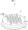
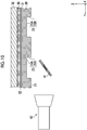
Fig. 1 is a perspective view illustrating an example of a plate precursor. -
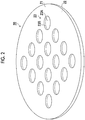
Fig. 2 is a perspective view of a thermoplastic resin plate. -
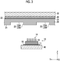
Fig. 3 is a step diagram illustrating a production method of a thermoplastic resin plate precursor. -
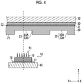
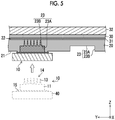
Fig. 4 is a step diagram illustrating the production method of a thermoplastic resin plate precursor. -
Fig. 5 is a step diagram illustrating the production method of a thermoplastic resin plate precursor. -
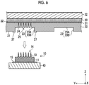
Fig. 6 is a step diagram illustrating the production method of a thermoplastic resin plate precursor. -
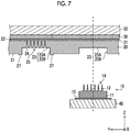
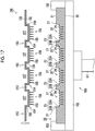
Fig. 7 is a step diagram illustrating the production method of a thermoplastic resin plate precursor. -
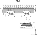
Fig. 8 is a step diagram illustrating the production method of a thermoplastic resin plate precursor. -
Fig. 9 is a step diagram illustrating the production method of a thermoplastic resin plate precursor. -
Fig. 10 is a step diagram illustrating the production method of a thermoplastic resin plate precursor. -
Fig. 11 is a perspective view illustrating another example of the plate precursor. -
Fig. 12 is a cross-sectional view illustrating a structure having a through-hole in a state where a plate precursor is attached to a plate precursor stage. -
Fig. 13 is a cross-sectional view illustrating another structure having a through-hole in a state where a plate precursor is attached to a plate precursor stage. -
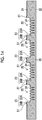
Fig. 14 is a step diagram illustrating a production method of a die by an electroforming treatment. -
Fig. 15 is a step diagram illustrating the production method of a die by an electroforming treatment. -
Fig. 16 is a step diagram illustrating the production method of a die by an electroforming treatment. -
Fig. 17 is a step diagram illustrating the production method of a die by an electroforming treatment. -
Fig. 18 is a perspective view of an electroform. -
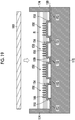
Fig. 19 is a step diagram illustrating a production method of a mold. -
Fig. 20 is a step diagram illustrating the production method of a mold. -
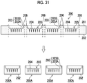
Fig. 21 is a step diagram illustrating a manufacturing method of a pattern sheet. -
Fig. 22 is a step diagram illustrating the manufacturing method of a pattern sheet. -
Fig. 23 is a step diagram illustrating the manufacturing method of a pattern sheet. -
Fig. 24 is a step diagram illustrating the manufacturing method of a pattern sheet. -
Fig. 25 is a perspective view of the pattern sheet. - Hereinafter, a production method of a mold having a recessed pattern in a recessed step portion and a manufacturing method of a pattern sheet according to the present invention will be described with reference to the accompanying drawings. The present invention is described by the following preferred embodiments. Modifications can be made by a number of techniques without departing from the scope of the invention. Therefore, all modifications within the scope of the present invention are included in the appended claims.
- Here, in the figures, like elements having similar functions are denoted by like reference numerals. In addition, in this specification, in a case where a numerical value range is expressed using "to", the numerical value range includes the numerical values of the upper limit and the lower limit indicated by "to".
- An embodiment of the present invention will be described with reference to the drawings. A production method of a mold having a recessed pattern in a recessed step portion includes: a plate precursor preparation step of preparing a plate precursor having a pedestal on which a protruding pattern formed by a plurality of protruding portions is disposed; a resin plate preparation step of preparing a thermoplastic resin plate in which a recessed step portion having a bottom surface and a wall surface is formed on a flat surface thereof, the recessed step portion having a volume equal to or less than a total volume of the protruding pattern and the pedestal; and a resin plate precursor production step of producing a thermoplastic resin plate precursor, the resin plate precursor production step including a positioning step of positioning the protruding pattern of the plate precursor and a center position of the recessed step portion by moving the plate precursor and the thermoplastic resin plate relative to each other, and a recessed pattern forming step of forming a recessed pattern having an inverted shape of the protruding pattern on the thermoplastic resin plate by pressing the protruding pattern of the heated plate precursor and the pedestal against the bottom surface of the recessed step portion, thereafter cooling the plate precursor, and separating the plate precursor from the thermoplastic resin plate.
- In the plate precursor preparation step, the plate precursor is prepared. As illustrated in
Fig. 1 , aplate precursor 10 has apedestal 11, a plurality of protrudingportions 13 formed on onemain surface 12 of thepedestal 11, and asubstrate 15 provided on a side opposite to themain surface 12 of thepedestal 11. Thesubstrate 15 is disposed so as to overlap thepedestal 11 in a plan view, and has an area larger than the area of thepedestal 11. The protrudingportion 13 is formed by afrustum portion 13B and atapered needle portion 13A in a direction away from themain surface 12. Thefrustum portion 13B includes a pyramidal frustum, a conical frustum, and the like. In addition, another frustum portion may be included between thefrustum portion 13B and theneedle portion 13A. - A protruding
pattern 14 is configured by arranging a plurality of the protrudingportions 13 on themain surface 12. Themain surface 12 corresponds to the surface on which the protrudingpattern 14 is disposed. The protrudingpattern 14 of theplate precursor 10 has a protruding pattern basically the same as a pattern sheet, such as a microneedle, having a protruding pattern to be produced. In the embodiment, the protrudingpattern 14 is configured by arranging the plurality of protrudingportions 13 in a circular shape. However, the number of the protrudingportions 13 and the positions of the protrudingportions 13 in the arrangement are not limited. By arranging the plurality of protrudingportions 13 in a matrix, the protrudingpattern 14 can be configured. Themain surface 12 may be a complete flat surface or a flat surface at first glance. - For example, the protruding
portion 13 is preferably set to a height of 0.1 mm to 2 mm from themain surface 12 of theplate precursor 10. The interval between adjacent protrudingportions 13 is preferably 0.3 mm to 2 mm. The aspect ratio of the protruding portion 13 (the height of the protruding portion / the width of the bottom surface of the protruding portion) is preferably 1 to 5. - The ratio between the height of the
needle portion 13A and the height of thefrustum portion 13B (the height of theneedle portion 13A / the height of thefrustum portion 13B) is preferably 1 to 10. The angle formed between the side surface of thefrustum portion 13B and themain surface 12 is preferably 10° to 60°. For example, thepedestal 11 can have a cylindrical shape having a diameter of 5 mm to 30 mm and a height of 0.2 mm to 2 mm. However, the shape of thepedestal 11 is not limited to the cylindrical shape, and may be a rectangular parallelepiped shape. Thesubstrate 15 may be formed integrally with the surface opposite to themain surface 12 of thepedestal 11 instead of being a member different from thepedestal 11. In this case, the volume of thesubstrate 15 is not included in the volume of thepedestal 11. - For example, the
plate precursor 10 having the protrudingpattern 14 is produced by machining a metal substrate, which is to become theplate precursor 10, using a cutting tool such as a diamond tool. As the metal substrate, stainless steel, an aluminum alloy, Ni, or the like can be used. - In the resin plate preparation step, the thermoplastic resin plate is prepared. As illustrated in
Fig. 2 , athermoplastic resin plate 20 has a main surface (flat surface) 21 and amain surface 22 which oppose each other, and is configured in a plate shape having a certain thickness. For example, thethermoplastic resin plate 20 can have a cylindrical shape having a thickness of 1 mm to 6 mm and a diameter of 150 mm to 300 mm. The shape of thethermoplastic resin plate 20 is not limited to the cylindrical shape, and may be a rectangular shape in a plan view. - A plurality of recessed
step portions 23 are formed on themain surface 21 of thethermoplastic resin plate 20. The recessedstep portion 23 is formed by abottom surface 23A and awall surface 23B surrounding thebottom surface 23A. The recessedstep portion 23 has a volume equal to or less than the total volume of the protrudingpattern 14 and thepedestal 11. However, in a case where the area of thebottom surface 23A of the recessedstep portion 23 is caused to be the same as the area of themain surface 12 of thepedestal 11 or smaller than the area of themain surface 12 in a plan view, the height of thewall surface 23B of the recessed step portion 23 (hereinafter, also referred to as "the height of the recessedstep portion 23"), that is, the length from thebottom surface 23A to themain surface 21 is caused to be shorter than the length from themain surface 12 of thepedestal 11 to the substrate 15 (hereinafter, referred to as "the height of thepedestal 11"). In the recessed pattern forming step, which will be described later, the height of the recessedstep portion 23 is caused to be shorter than the height of thepedestal 11 by the height by which the amount of the resin that is pressed and pushed away in a case where the protrudingpattern 14 and thepedestal 11 of theplate precursor 10 are pressed against thebottom surface 23A of the recessedstep portion 23 flows out of the recessedstep portion 23 and spreads by coming into contact with themain surface 21 and thesubstrate 15 of theplate precursor 10. Accordingly, the protrudingpattern 14 formed on the main surface of thepedestal 11 can be pressed against thebottom surface 23A of the recessedstep portion 23. For example, the length from thebottom surface 23A to themain surface 21 can be set to a length obtained by subtracting the height (50 µm) of the resin portion that is pushed away from the height (0.2 mm to 2 mm) of thepedestal 11. - The shape of the
bottom surface 23A of the recessedstep portion 23 is preferably the same shape as themain surface 12 of thepedestal 11 in a plan view. By causing the shape of the recessedstep portion 23 to be the same as that of themain surface 12 and causing the area of the recessedstep portion 23 to be the same as or smaller than the area of themain surface 12, the entire region of the recessedstep portion 23 can be pressed by themain surface 12 of thepedestal 11. In addition, in a case where the length from thebottom surface 23A to themain surface 21 is caused to be the same as the length from themain surface 12 of thepedestal 11 to thesubstrate 15, the area of the recessedstep portion 23 is increased by the amount of the resin pushed away by the protrudingpattern 14, whereby themain surface 21 of a thermoplastic resin plate precursor to be manufactured can be made flat. - The thermoplastic resin forming the
thermoplastic resin plate 20 is not particularly limited. For example, polyethylene terephthalate, polycarbonate, polymethyl methacrylate, polystyrene, linear low density polyethylene (LLDPE), liquid crystal polymers, polylactic acid, and the like can be suitably used. For example, thethermoplastic resin plate 20 can be manufactured by injection molding using a thermoplastic resin. - As illustrated in
Fig. 3 , thethermoplastic resin plate 20 and aquartz substrate 30 are bonded by a double-sided adhesive film 31 on themain surface 22 side. The surface of thequartz substrate 30 on the side opposite to the double-sided adhesive film 31 is attached to awork stage 32. Thework stage 32 has an X-axis drive mechanism and a Y-axis drive mechanism (not illustrated) that move in directions orthogonal to each other on a horizontal plane, and can move in an X direction and a Y direction. - For example, the
quartz substrate 30 preferably has the same shape and the same area as thethermoplastic resin plate 20 in a plan view. Thequartz substrate 30 functions as a reinforcing member for maintaining the rigidity of thethermoplastic resin plate 20. - The
plate precursor 10 having the protrudingpattern 14 is attached to aplate precursor stage 40. Theplate precursor stage 40 has a Z-axis drive mechanism (not illustrated) and can move along a Z-axis direction. Theplate precursor 10 is heated to a temperature at which thethermoplastic resin plate 20 is softened. Heating is performed by a heater (not illustrated). Depending on the thermoplastic resin forming thethermoplastic resin plate 20, theplate precursor 10 is heated to an appropriate temperature. - The protruding
pattern 14 of theplate precursor 10 and thebottom surface 23A of thethermoplastic resin plate 20 are arranged so as to face each other. - Next, the resin plate precursor production step will be described. The resin plate precursor production step includes the positioning step and the recessed pattern forming step.
- In the positioning step illustrated in
Fig. 4 , theplate precursor 10 and thethermoplastic resin plate 20 are moved relative to each other such that theplate precursor 10 and the center position of the recessedstep portion 23 are positioned. In the positioning step of the embodiment, thework stage 32 that supports thethermoplastic resin plate 20 is moved by driving the X-axis drive mechanism and the Y-axis drive mechanism (not illustrated) such that the center position of the recessedstep portion 23 and theplate precursor 10 are positioned. In the positioning, the center position of the recessedstep portion 23 and the center position of the protrudingpattern 14 are positioned. - As long as the
plate precursor 10 and thethermoplastic resin plate 20 can be moved relative to each other, either one or both of theplate precursor 10 or thethermoplastic resin plate 20 may be moved. - Since the center position of the recessed
step portion 23 and theplate precursor 10 are positioned, a protrudingpattern 303 of apattern sheet 300 and the center position of asheet portion 301 illustrated inFig. 25 can be positioned. - Next, in the recessed pattern forming step illustrated in
Fig. 5 , the heated protrudingpattern 14 of theplate precursor 10 is pressed against thebottom surface 23A of thethermoplastic resin plate 20. As illustrated inFig. 5 , the plurality of protrudingportions 13 forming the protrudingpattern 14 are pressed against thebottom surface 23A of thethermoplastic resin plate 20. - In the
plate precursor 10 and thethermoplastic resin plate 20 illustrated inFig. 5 , themain surface 12 of thepedestal 11 and the recessedstep portion 23 are the same in area and shape, and the height of thepedestal 11 is lower than the height of the recessedstep portion 23 by the amount of the resin pushed away by the protrudingpattern 14. In a case where theplate precursor 10 is pressed against thethermoplastic resin plate 20, thepedestal 11 of theplate precursor 10 presses thebottom surface 23A and thewall surface 23B of the recessedstep portion 23 such that the recessedstep portion 23 is transferred to the inverted shape of thepedestal 11 and the protrudingpattern 14. The resin corresponding to recesses 24 (seeFig. 6 ) formed by pressing theplate precursor 10 flows into the gap between thesubstrate 15 of theplate precursor 10 and themain surface 21 of thethermoplastic resin plate 20 as illustrated inFig. 5 . The resin that has flowed in spreads between thesubstrate 15 and themain surface 21. - In the pressing of the embodiment, by driving the Z-axis drive mechanism, the
plate precursor 10 is moved along the Z direction toward thebottom surface 23A such that the protrudingpattern 14 is pressed against thebottom surface 23A. As long as the protrudingpattern 14 can be pressed against thebottom surface 23A, either one or both of theplate precursor 10 and thethermoplastic resin plate 20 may be moved in the Z direction. - The protruding
pattern 14 of theheated plate precursor 10 is pressed against thebottom surface 23A of the recessedstep portion 23 with a predetermined pressing force and a time. Thebottom surface 23A of thethermoplastic resin plate 20 is heated to the softening temperature or higher by pressing theprotruding pattern 14 of theheated plate precursor 10. By cooling theplate precursor 10 in a state where the pressed protrudingpattern 14 is in contact with thebottom surface 23A of thethermoplastic resin plate 20, thethermoplastic resin plate 20 is cooled to a softening temperature or lower. - As described above, the height of the
pedestal 11 is set in consideration of the height of the recessedstep portion 23 and the resin that is pushed away by the pressing. In a case where the height of thepedestal 11 is increased and thesubstrate 15 and the resin that is pushed away do not come into contact with each other, the shape of the surface of the produced thermoplastic resin plate precursor is not stable, which is not preferable. Furthermore, in a case where themain surface 12 of thepedestal 11 and thebottom surface 23A of the recessedstep portion 23 do not come into contact with each other, the protrudingportions 13 of the protrudingpattern 14 are not stably transferred to the recessedstep portion 23, which is not preferable. In a case where the resin that is pushed away corresponds to the volume of the protrudingpattern 14, for example, by causing the height of thepedestal 11 to be higher than the height of the recessed step portion by 50 µm, a recessed step portion having a well-shaped recessed pattern can be formed. - Next, in the recessed pattern forming step illustrated in
Fig. 6 , theplate precursor 10 and thethermoplastic resin plate 20 are separated from each other. On thebottom surface 23A of thethermoplastic resin plate 20, a plurality of therecesses 24 that are the inverted shapes of the plurality of protrudingportions 13 are formed. By arranging the plurality ofrecesses 24 on thebottom surface 23A of thethermoplastic resin plate 20, a recessedpattern 25 is formed. Furthermore, themain surface 21 of thethermoplastic resin plate 20 has aprotrusion 27 formed continuously from the recessedstep portion 23. The surface of theprotrusion 27 spreads along thesubstrate 15 of theplate precursor 10 and is thus formed flat. Among the side surfaces of theprotrusion 27, the side surface on the recessedstep portion 23 side is pressed by thepedestal 11 of theplate precursor 10, and is thus formed continuously from thewall surface 23B of the recessedstep portion 23. Furthermore, regarding the side surface on the opposite side, since the resin pushed away spreads along thesubstrate 15 of theplate precursor 10 in the case where the plate precursor is pressed, the surface side of theprotrusion 27 spreads toward themain surface 21 side of thethermoplastic resin plate 20. Therefore, theprotrusion 27 is configured in an inverted tapered structure which spreads from themain surface 21 of thethermoplastic resin plate 20 toward the surface of theprotrusion 27. In the pressing of the embodiment, by driving the Z-axis drive mechanism, theplate precursor 10 is moved in the direction away from thebottom surface 23A along the Z direction, such that theplate precursor 10 and thethermoplastic resin plate 20 are separated from each other. - In a case where the recessed
pattern 25 is formed in the recessedstep portion 23, theplate precursor 10 and thethermoplastic resin plate 20 are moved relative to each other in the positioning step illustrated inFig. 7 , such that theplate precursor 10 and the center position of the recessedstep portion 23 where the recessedpattern 25 is not formed are positioned. As inFig. 4 , the center position of the recessedstep portion 23 and theplate precursor 10 are positioned by moving thework stage 32 that supports thethermoplastic resin plate 20. - In the recessed pattern forming step illustrated in
Fig. 8 , similarly toFigs. 5 and6 , the protrudingpattern 14 of theheated plate precursor 10 is pressed against thebottom surface 23A of thethermoplastic resin plate 20. The protrudingpattern 14 of theheated plate precursor 10 is pressed against thebottom surface 23A of the recessedstep portion 23 with a predetermined pressing force and a time. Next, theplate precursor 10 is cooled in a state where the pressed protrudingpattern 14 is in contact with thebottom surface 23A of thethermoplastic resin plate 20. By separating theplate precursor 10 and thethermoplastic resin plate 20 from each other, a plurality of therecesses 24 that are the inverted shapes of the plurality of protrudingportions 13 are formed on thebottom surface 23A of thethermoplastic resin plate 20. Until the recessedpattern 25 is formed in all the recessedstep portions 23 of thethermoplastic resin plate 20, the positioning step and the recessed pattern forming step illustrated inFigs. 4 to 8 are repeated. By forming the recessedpattern 25 in all the recessedstep portions 23 of thethermoplastic resin plate 20, a thermoplasticresin plate precursor 26 is produced from thethermoplastic resin plate 20. - Next, in the positioning step, a method for calculating the positional deviation amount of the
plate precursor 10 and a method for calculating the center position of the recessedstep portion 23 of thethermoplastic resin plate 20 will be described. - As illustrated in
Fig. 3 , theplate precursor 10 is attached to theplate precursor stage 40 having the Z-axis drive mechanism (not illustrated). The laminate in which thethermoplastic resin plate 20 and thequartz substrate 30 are laminated is attached to thework stage 32 having the X-axis drive mechanism and the Y-axis drive mechanism (not illustrated) which are installed to face theplate precursor 10. The X axis, Y axis, and Z axis in this state are defined as Xo, Y0, and Z0. - A method of calculating a positional deviation amount of the
plate precursor 10 will be described with reference toFig. 9 . Thework stage 32 is moved to predetermined coordinates (X1b,Yib). Theheated plate precursor 10 is pressed against thebottom surface 23A of the recessedstep portion 23 of thethermoplastic resin plate 20 in the Z-axis direction by theplate precursor stage 40. Next, theplate precursor 10 is separated from thethermoplastic resin plate 20 after being cooled, and theplate precursor 10 is returned to the initial position Zo by theplate precursor stage 40. The inverted structure of the protrudingpattern 14 is transferred to thebottom surface 23A (Xib,Yib) of thethermoplastic resin plate 20, such that the recessedpattern 25 is formed. - An
imaging device 60 included in an image processing system is disposed at a position of a fixed point (Xc,Yc,Zc). As illustrated inFig. 9 , theimaging device 60 is installed at a position where the optical axis of theimaging device 60 is parallel to an installation surface of thework stage 32, that is, the surface on which thequartz substrate 30 is installed. Amirror 61 is installed on the optical axis of theimaging device 60 and between thethermoplastic resin plate 20 and theplate precursor 10. A light source is irradiated in the same direction as the optical axis of theimaging device 60. Theimaging device 60 comprises an imaging element such as a charge coupled device (CCD) or a complementary metal oxide semiconductor (CMOS). - A center (Xim,Yim) of the recessed
pattern 25 formed at the position (Xib,Yib) of thethermoplastic resin plate 20 is detected by theimaging device 60 installed at the fixed point. As the positional deviation amount of theplate precursor 10, (Xib - Xim) for the X direction and (Yib - Yim) for the Y direction can be calculated. - A method of calculating the center position of the recessed
step portion 23 of thethermoplastic resin plate 20 will be described with reference toFig. 10 . In a state where theimaging device 60 is fixed to the fixed point (Xc,Yc,Zc), thethermoplastic resin plate 20 is moved in the X direction and the Y direction by thework stage 32 to detect the coordinates (Xn,Yn) of the center position of all k recessedstep portions 23 formed in the thermoplastic resin plate 20 (here, n = 1 to k). - In the positioning step, the
work stage 32 is moved to (X1 - (Xib - Xim),Y1 - (Yib - Yim)) based on the calculated center position of the recessedstep portion 23 and the result of the positional deviation amount of theplate precursor 10. The center position of the recessedstep portion 23 at n = 1 can be caused to coincide with the center position of the protrudingpattern 14 of theplate precursor 10. The term "coincide" includes a case of perfect coincidence and a case of having an allowable deviation. Theheated plate precursor 10 is moved along the Z direction by theplate precursor stage 40. The protrudingpattern 14 is pressed against thebottom surface 23A of the recessedstep portion 23 with a constant pressing force and a time. After theplate precursor 10 is cooled, theplate precursor 10 is separated from thethermoplastic resin plate 20 and returned to the Z0 position. The recessedpattern 25 can be formed at the center position (X1,Y1) of the recessedstep portion 23 at n = 1 formed in thethermoplastic resin plate 20. For the remaining (k - 1) recessed step portions 23 (n = 2 to k), thework stage 32 is moved to Xn - (Xib - Xim), Yn - (Yib - Yim)). In the same manner as described above, theheated plate precursor 10 is pressed by theplate precursor stage 40. After theplate precursor 10 is cooled, theplate precursor 10 is separated from thethermoplastic resin plate 20 and returned to the Z0 position. By repeating the positioning step and the recessed pattern forming step, the recessedpattern 25 that is the inverted structure of the protrudingpattern 14 can be formed at the center position (Xn,Yn) of the k recessed step portions 23 (here, n = 1to k). In a case where the series of steps are finished, the thermoplasticresin plate precursor 26 in which the recessedpattern 25 is formed in the plurality of recessedstep portions 23 is produced. In the thermoplasticresin plate precursor 26 of the embodiment, inFig. 8 , the center position of the recessedpattern 25 and the center position of the recessedstep portion 23 coincide with each other. -
Fig. 11 is a perspective view illustrating another example of the plate precursor. Aplate precursor 310 illustrated inFig. 11 is different from theplate precursor 10 illustrated inFig. 1 in that asubstrate 315 has a through-hole 317. The through-hole 317 is formed through thesubstrate 315 in the height direction of thepedestal 11 along the side surface of thepedestal 11 at anedge portion 316 where the side surface of thepedestal 11 and thesubstrate 315 are in contact with each other. By providing the through-hole 317, air in the recessedstep portion 23 in a case of pressing theplate precursor 10 against the recessedstep portion 23 can be released from the through-hole 317. By allowing the air to be released from the through-hole 317, it is possible to prevent the air from being collected at the contact portion between theplate precursor 10 and thethermoplastic resin plate 20. Therefore, the shape of the recessedstep portion 23 after forming the recessed pattern can be stably formed. In theplate precursor 310 illustrated inFig. 11 , the through-hole 317 provided in thesubstrate 315 is formed over one circumference along the side surface of thepedestal 11. However, during use, since theplate precursor 310 is attached to theplate precursor stage 40 to be used, thesubstrate 315 can be used even in a case of being divided by the through-hole 317. -
Fig. 12 is a cross-sectional view illustrating astructure 418 having a through-hole 417 in a state where aplate precursor 410 is attached to aplate precursor stage 440. Theplate precursor 410 illustrated inFig. 12 has aprotrusion 419 at the side surface of thepedestal 11 on an end portion on the side opposite to themain surface 12. Theplate precursor 410 is attached to theplate precursor stage 440 by sandwiching theprotrusion 419 between theplate precursor stage 440 and a holdingmember 420. Theplate precursor stage 440 and the holdingmember 420 can be attached byscrews 421. The through-hole 417 is formed by the side surface of thepedestal 11 and the side surface of the holdingmember 420. In thestructure 418 inFig. 12 , a protrudingsurface 422 of the holdingmember 420 on the side opposite to theplate precursor stage 440 has the same function as thesubstrate 315 illustrated inFig. 11 . -
Fig. 13 is a cross-sectional view illustrating astructure 518 having a through-hole 517 in a state where aplate precursor 510 is attached to aplate precursor stage 540. Theplate precursor stage 540 of thestructure 518 illustrated inFig. 13 has arecess 523 in which a part of theplate precursor 510 is stored in the center. The side of theplate precursor 510 opposite to themain surface 12 is configured to have a diameter smaller than the diameter of themain surface 12 through astep portion 524 so as to be accommodated in therecess 523. Theplate precursor stage 540 and theplate precursor 510 can be attached by ascrew 521. A through-hole 517 is formed in a left-right direction inFig. 13 by a protruding surface 522 provided in theplate precursor stage 540 and thestep portion 524 of theplate precursor 510. In addition, the through-hole 517 is formed continuously in the height direction by forming a gap between the inner peripheral surface of therecess 523 and the side surface of theplate precursor 510. Also in thestructure 518 illustrated inFig. 13 , the protruding surface 522 formed on theplate precursor stage 540 has the same function as thesubstrate 315 illustrated inFig. 11 . - Next, a die production step of producing a die having a protruding step portion in which a protruding pattern is disposed by an electroforming treatment using the thermoplastic
resin plate precursor 26 will be described. As illustrated inFig. 14 , the thermoplasticresin plate precursor 26 in which the recessedpattern 25 is formed in the plurality of recessedstep portions 23 is prepared. A conduction treatment is performed on the thermoplasticresin plate precursor 26. In the conduction treatment, a metal film (for example, nickel) is formed on themain surface 21, the bottom surfaces 23A and the wall surfaces 23B forming the recessedstep portions 23, the plurality ofrecesses 24 forming the recessedpatterns 25, and theprotrusions 27 of the thermoplasticresin plate precursor 26 by vapor deposition, sputtering, or the like. - As illustrated in
Fig. 15 , the thermoplasticresin plate precursor 26 subjected to the conduction treatment is fixed to acathode 100 used for the electroforming treatment. Thecathode 100 comprises at least ashaft 101 or acathode plate 102. The thermoplasticresin plate precursor 26 is fixed to thecathode plate 102 at a position where themain surface 22 of the thermoplasticresin plate precursor 26 and thecathode plate 102 face each other. - In order to supply a current from the
cathode plate 102 to the metal film (not illustrated) formed on the thermoplasticresin plate precursor 26, aconductive ring 103 is provided at the outer peripheral portion of the thermoplasticresin plate precursor 26. Theshaft 101 and thecathode plate 102 are formed of a conductive member. Here, the electroforming treatment refers to a treatment method of depositing metal on the thermoplasticresin plate precursor 26 by an electroplating method. - As illustrated in
Fig. 16 , the thermoplasticresin plate precursor 26 attached to thecathode 100 is immersed in anelectroforming liquid 132. Anelectroforming apparatus 130 for performing the electroforming treatment on the thermoplasticresin plate precursor 26 comprises anelectroforming tank 134 that holds theelectroforming liquid 132, adrain tank 136 that receives an overflowingelectroforming liquid 132A from theelectroforming tank 134, and atitanium case 140 filled withNi pellets 138. By immersing thecathode 100 having the thermoplasticresin plate precursor 26 attached thereto in theelectroforming liquid 132, theelectroforming apparatus 130 operates. As theelectroforming liquid 132, for example, a liquid in which 400 g/L to 800 g/L of nickel sulfamate, 20 g/L to 50 g/L of boric acid, and necessary additives such as a surfactant (for example, sodium lauryl sulfate) are mixed can be used. The temperature of theelectroforming liquid 132 is preferably 40°C to 60°C. - A
drain pipe 142 is connected to thedrain tank 136, and asupply pipe 144 is connected to theelectroforming tank 134. Theelectroforming liquid 132 overflowing from theelectroforming tank 134 to thedrain tank 136 is recovered by thedrain pipe 142, and the recoveredelectroforming liquid 132 is supplied from thesupply pipe 144 to theelectroforming tank 134. The thermoplasticresin plate precursor 26 held by thecathode 100 is aligned with a position at which themain surface 21 on which the recessedpatterns 25 are formed faces thetitanium case 140 serving as an anode. - The
cathode 100 is connected to a negative electrode, and a positive electrode is connected to thetitanium case 140 serving as the anode. A direct current voltage is applied between thecathode 100 and thetitanium case 140 while the thermoplasticresin plate precursor 26 held by thecathode plate 102 is rotated about theshaft 101 at a rotational speed of 10 rpm to 150 rpm. TheNi pellets 138 are dissolved, and a metal film is attached to themain surface 21, the bottom surfaces 23A and the wall surfaces 23B of the recessedstep portions 23, and the inner walls of the recessedpatterns 25 of the thermoplasticresin plate precursor 26 attached to thecathode 100. - As an
electroformed die 150 made of the metal film is formed on the thermoplasticresin plate precursor 26, as illustrated inFig. 17 , thecathode 100 to which the thermoplasticresin plate precursor 26 is attached is taken out from the electroforming tank 134 (not illustrated). Next, thedie 150 is peeled from the thermoplasticresin plate precursor 26. Thedie 150 has amain surface 152 and amain surface 158 that oppose each other. Thedie 150 hasflat portions 153 and protrudingstep portions 154 in a cross-sectional view. A plurality of protrudingportions 155 are formed on themain surface 152 of the protrudingstep portion 154, and the plurality of protrudingportions 155 form aprotruding pattern 156. The protrudingpattern 156 has an inverted shape of the recessedpattern 25 of the thermoplasticresin plate precursor 26. The protrudingstep portion 154 has an inverted shape of the recessedstep portion 23. Furthermore, recesses 159 corresponding to theprotrusions 27 of the thermoplasticresin plate precursor 26 are formed on themain surface 152 of theflat portion 153. - The positional relationship between the
flat portion 153 and the protrudingstep portion 154 means a state where the respectivemain surfaces 152 thereof are not on the same plane.Cylindrical recesses 157 having a constant diameter are provided on themain surface 158 side of the protrudingstep portions 154. For example, thedie 150 has a thickness of 150 µm. The thickness is the distance between themain surface 152 and themain surface 158. -
Fig. 18 is a perspective view of thedie 150. As illustrated inFig. 18 , in the embodiment, the protrudingpattern 156 is configured by circularly arranging the plurality of protrudingportions 155 on themain surface 152 of the protrudingstep portion 154. Since the protrudingstep portion 154 and theprotruding pattern 156 are formed by the thermoplasticresin plate precursor 26, the center position of the protrudingstep portion 154 and the center position of theprotruding pattern 156 coincide with each other. The term "coincide" includes a case of perfect coincidence and a case of having an allowable deviation. - The protruding
step portion 154 has a cylindrical pedestal shape having a certain height. The height of the protrudingstep portion 154 is the height of the recessed step portion of the thermoplasticresin plate precursor 26. The height of the protrudingstep portion 154 is the distance between themain surface 152 of the protrudingstep portion 154 and themain surface 152 of the flat portion 153 (the bottom surface of the recess 159). - The protruding
portion 155 is formed by afrustum portion 155B and atapered needle portion 155A in a direction away from themain surface 152 of the protrudingstep portion 154. Thefrustum portion 155B includes a pyramidal frustum, a conical frustum, and the like. In addition, another frustum portion may be included between thefrustum portion 155B and theneedle portion 155A. - The height of the protruding
portion 155 is, for example, in a range of 0.1 mm to 2 mm, and preferably 0.3 mm or more and 1.5 mm or less. The height of the protrudingportion 155 is the distance from themain surface 152 of the protrudingstep portion 154 to the tip of the protrudingportion 155. - In the electroforming treatment, in order to form a metal film of a uniform thickness on the thermoplastic
resin plate precursor 26, thedie 150 preferably has a circular shape in a plan view. The diameter of thedie 150 is preferably 200 mm to 300 mm. The circular shape is not limited to a perfect circle and may be a substantially circular shape. - Next, a mold production step using the
die 150 will be described. A thermosetting resin such as an epoxy resin or a silicone resin as a mold material is prepared. In particular, it is preferable to use a silicone resin. Among silicone resins, there are one-component thermosetting silicone materials, two-component mixed curable silicone materials, UV-curable silicone materials, and the like. As a medical silicone resin, a two-component mixed curable silicone material in which a main agent and a curing agent are mixed is applied. For example, MED-6015 manufactured by Nusil can be applied as the silicone resin. - As illustrated in
Fig. 19 , in the mold production step, installation surfaces of theflat portion 153 of thedie 150 and aninstallation pedestal 172 are arranged to face each other, and thedie 150 is fixed to theinstallation pedestal 172. An end portion of thedie 150 is pressured between aweir member 174 and theinstallation pedestal 172. A predetermined amount of a resin R is added dropwise from the protrudingstep portion 154 side of thedie 150. Next, the resin R is lightly pressed by asheet 180 made of, for example, polyethylene terephthalate (PET). - Next, in a state where the
sheet 180 is brought into contact with the resin R, thesheet 180 is placed in an oven heated to 120°C and heated for 30 minutes. The resin R is cured to produce a mold. - As illustrated in
Fig. 20 , amold 200 is separated from thedie 150. The inverted shape of the protrudingstep portions 154 of thedie 150 and the protrudingpatterns 156 formed by the plurality of protrudingportions 155 is formed in themold 200. - The
mold 200 has amain surface 201 and amain surface 202 which oppose each other. Recessedstep portions 203 are formed on themain surface 201 side. The recessedstep portion 203 is formed by abottom surface 203A and awall surface 203B. A plurality ofrecesses 204 are formed on thebottom surface 203A of the recessedstep portion 203. In addition, on themain surface 201 side,protrusions 206 corresponding to therecesses 159 of thedie 150 are formed. A recessedpattern 205 is configured by arranging a plurality of therecesses 204 on thebottom surface 203A of the recessedstep portion 203. Since the recessedstep portion 203 and the recessedpattern 205 are formed by thedie 150, the center position of the recessedstep portion 203 and the center position of the recessedpattern 205 coincide with each other. The term "coincide" includes a case of perfect coincidence and a case of having an allowable deviation. - Next, a method of manufacturing a pattern sheet using the
mold 200 produced in the above-described production method will be described.Figs. 21 to 24 are step diagrams for manufacturing apattern sheet 300. A microneedle array will be described as an example of thepattern sheet 300. -
Fig. 21 illustrates a state wheremolds 200A are prepared. Themolds 200A of the embodiment are produced by punching out themold 200 manufactured by the above-described mold production method in units of the recessedstep portions 203. Themold 200A has the recessedpattern 205 formed in the recessedstep portion 203. InFig. 21 , the punching is performed so that the step between theprotrusion 206 and themain surface 201 is not included in themold 200A, but the position where themold 200A is punched out is not limited. Regarding injection of a polymer solution, which will be described later, since the polymer solution is held inside the recessedstep portion 203, the pattern sheet can be manufactured without being affected by the step between theprotrusion 206 and themain surface 201. - The
mold 200A is installed on a suction pedestal (not illustrated) in a direction in which the recessedstep portion 203 is open. Themold 200A is fixed on the suction pedestal by being suctioned with a predetermined gauge pressure from themain surface 202 side of themold 200A. -
Fig. 22 is a diagram illustrating a supplying step of supplying apolymer solution 212 that is a liquid material to the recessedpattern 205 formed in the recessedstep portion 203 of themold 200A. - As the material of the
polymer solution 212 forming thepattern sheet 300, it is preferable to use a water-soluble material. As a material of a resin polymer of thepolymer solution 212 used to manufacture thepattern sheet 300, it is preferable to use a biocompatible resin. As such resins, sugars such as glucose, maltose, pullulan, sodium chondroitin sulfate, sodium hyaluronate, and hydroxyethyl starch, proteins such as gelatin, and biodegradable polymers such as polylactic acid and a lactic acid-glycolic acid copolymer are preferably used. In a case where thepattern sheet 300 is released from themold 200A, thepattern sheet 300 can be released using a base material (not illustrated), so that such resins can be suitably used. Although a concentration varies depending on the material, it is preferable that the concentration is set so that the resin polymer is contained at 10 mass% to 50 mass% in thepolymer solution 212 which does not contain a drug. A solvent used in thepolymer solution 212 may be warm water or may be volatile, and alcohol such as ethanol or the like may be used. In addition, it is possible to dissolve the drug, which is supplied into the body according to the application, in thepolymer solution 212. The polymer concentration of thepolymer solution 212 containing the drug (the concentration of the polymer excluding the drug in a case where the drug itself is a polymer) is preferably 0 to 30 mass%. - As a method of preparing the
polymer solution 212, in a case where a water-soluble polymer (such as gelatin) is used, a water-soluble powder may be dissolved in water and the drug may be added after the dissolution. Otherwise, a powder of a water-soluble polymer may be dissolved in a liquid in which the drug is dissolved. In a case where it is difficult to dissolve the polymer in water, heating may be performed for dissolution. The temperature can be appropriately selected depending on the kind of the polymer material, and it is preferable that heating is performed at a temperature of about 20°C to 40°C as necessary. For the solution containing the drug, the viscosity of thepolymer solution 212 is preferably 200 mPa·s or less, and more preferably 50 mPa·s or less. For a solution which does not contain a drug, the viscosity is preferably 2000 mPa·s or less, and more preferably 500 mPa·s or less. By appropriately adjusting the viscosity of thepolymer solution 212, thepolymer solution 212 can be easily injected into the recessedpatterns 205 of themold 200A. For example, the viscosity of thepolymer solution 212 can be measured with a capillary viscometer, a falling ball viscometer, a rotational viscometer, or a vibrational viscometer. It is preferable to remove gas in thepolymer solution 212 by a degassing device or the like before supplying thepolymer solution 212 to themold 200A. - The drug to be contained in the
polymer solution 212 is not particularly limited as long as the drug has a function of a drug. In particular, the drug is preferably selected from peptides, proteins, nucleic acids, polysaccharides, vaccines, pharmaceutical compounds that belong to a water-soluble low molecular weight compound, or cosmetic ingredients. - Examples of a method of injecting the
polymer solution 212 into themold 200A include application using a spin coater. For example, thepolymer solution 212 is supplied so as to protrude from the protrusion 206 (seeFig. 21 ) of themold 200A inside the recessedstep portion 203. Since themold 200A of the embodiment has the recessedstep portion 203, thepolymer solution 212 can be held. Since themold 200A is suctioned from themain surface 202 in a state where thepolymer solution 212 is held, thepolymer solution 212 can be filled up to the recess tip of therecesses 204 forming the recessedpattern 205. - It is preferable to form a through-hole at the recess tip of the
recess 204. The air in therecess 204 can escape from the through-hole. Therefore, thepolymer solution 212 can easily fill therecess 204 of themold 200A. In addition, this step is preferably performed in a decompressed state. -
Fig. 23 is a diagram illustrating a step of drying and solidifying thepolymer solution 212 to form thepattern sheet 300. For example, thepolymer solution 212 can be dried by heating themold 200A and blowing air to thepolymer solution 212. The moisture content of thepattern sheet 300 and the like are appropriately set. In addition, as the moisture content of thepattern sheet 300 becomes too low due to the drying, it becomes difficult to peel off thepattern sheet 300. Therefore, it is preferable to keep the moisture content in a state of maintaining elasticity. -
Fig. 24 is a diagram for describing a releasing step of releasing thepattern sheet 300 from themold 200A. Thepattern sheet 300 includes asheet portion 301 and a plurality of protrudingportions 302 formed on thesheet portion 301. A protrudingpattern 303 is formed by the plurality of protrudingportions 302. The protrudingpattern 303 is an inverted shape of the recessedpattern 205 of themold 200A. In thepattern sheet 300, the center position of theprotruding pattern 303 and the center position of thesheet portion 301 coincide with each other. The term "coincide" includes a case of perfect coincidence and a case of having an allowable deviation. In thepattern sheet 300, since the positions of theprotruding pattern 303 and thesheet portion 301 are accurately positioned, for example, in a case where thepattern sheet 300 is handled, the protrudingpattern 303 can be prevented from being damaged. - As described above, in the manufacturing of the pattern sheet, in order to hold the
polymer solution 212 in the recessedstep portion 203, the recessedstep portion 23 of the thermoplasticresin plate precursor 26 for producing themold 200 is formed into a transfer shape of theplate precursor 10. Therefore, a pattern sheet having a stable shape can be manufactured. In addition, thepattern sheet 300 can be formed without being affected by theprotrusion 206 formed outside the recessedstep portion 203. -
Fig. 25 is a perspective view of thepattern sheet 300. The protrudingportion 302 formed on thesheet portion 301 of thepattern sheet 300 is formed by a frustum portion 302B and atapered needle portion 302A in a direction away from thesheet portion 301. The frustum portion 302B includes a pyramidal frustum, a conical frustum, and the like. In addition, another frustum portion may be included between the frustum portion 302B and theneedle portion 302A. - In the embodiment, the case where the
pattern sheet 300 is produced by supplying thepolymer solution 212 to the recessedstep portion 203 formed in the recessedpattern 205 of themold 200A and drying the resultant has been described above, but the production of thepattern sheet 300 is not limited thereto. - For example, a
pattern sheet 300 having a two-layer structure can be manufactured by filling the recessedpattern 205 of themold 200A with thepolymer solution 212 containing the drug, drying the resultant, thereafter supplying thepolymer solution 212 containing no drug to the recessedstep portion 203 of themold 200A, and drying the resultant. - In addition, there may be cases where the
mold 200A is used only once and is preferably disposable. In a case where thepattern sheet 300 is used as a medicine, thepattern sheet 300 is preferably disposable in consideration of the safety of the manufacturedpattern sheet 300 for the living body. By making thepattern sheet 300 disposable, there is no need to clean themold 200A, so that the cost of the cleaning can be reduced. In particular, in a case where thepattern sheet 300 is used as a medicine, high cleaning performance is required, so that the cleaning cost is high. - The protruding
pattern 303 of the manufacturedpattern sheet 300 refers to a state where the plurality of protrudingportions 302 are arranged in an array in a predetermined number at predetermined positions. The protrudingportion 302 means a shape tapered toward the tip and includes a cone shape and a multistage cone shape. The multistage cone shape means a cone shape having sides at different angles from the bottom to the tip. - The height of the protruding
portion 302 is in a range of 0.2 mm to 2 mm, preferably 0.3 mm to 1.5 mm. - According to the production method of the mold having the recessed pattern in the recessed step portion of the present invention, the shapes of the recessed pattern of the thermoplastic resin plate precursor for producing the mold and the recessed step portion on which the recessed pattern is formed can be stably formed. Therefore, in subsequent steps, an electroform and a mold can be produced stably. Moreover, by manufacturing a pattern sheet using the produced mold, work can be easily performed, and a pattern sheet having a stable shape can be manufactured.
- The technical scope of the present invention is not limited to the scope described in the above embodiment. The configurations and the like in the embodiments can be appropriately combined between the embodiments without departing from the gist of the present invention.
- Hereinafter, the present invention will be described in more detail with reference to examples of the present invention. In addition, the material, use amount, ratio, processing content, processing procedure, and the like described in the following examples can be modified as appropriate without departing from the gist of the present invention. Therefore, the scope of the present invention should not be construed as being limited by the specific examples shown below.
- A cylindrical pedestal having a diameter φ of 17.0 mm and a height of 0.5 mm was formed at the center of a smooth aluminum alloy plate having dimensions of 6 × 4 cm and a thickness of t of 0.5 cm. 121 protruding portions having a needle-like structure in which a cone having a diameter φ of 0.4 mm and a height of 0.9 mm is formed on a conical frustum having a bottom diameter φ of 0.8 mm, a top diameter φ of 0.4 mm, and a height of 0.2 mm were cut at the center of the cylindrical pedestal in a circular close-packed arrangement at a pitch of 1 mm, whereby a plate precursor was obtained.
- A plate made of LLDPE, in which 24 recessed steps having a diameter φ of 17.0 mm and a depth of 0.45 mm were provided in a close-packed arrangement on a flat plate having a diameter φ of 20 cm and a thickness of 0.3 cm, was produced by injection molding.
- A quartz substrate having a φ of 20 cm and a thickness t of 0.2 mm was laminated on the surface of the thermoplastic resin plate opposite to the surface where the recessed steps were formed, via a double-sided adhesive film.
- The plate precursor was attached and fixed to a plate precursor stage having a Z-axis drive. The laminate obtained by laminating the thermoplastic resin plate and the quartz substrate was attached and fixed to a work stage having an X-Y-axis drive installed opposing the plate precursor (the X-axis, the Y-axis, and the Z-Axis at this time were X0, Y0, and Zo, respectively).
- The work stage was moved to predetermined Xib and Yib coordinates, the plate precursor was heated to 120°C, the thermoplastic resin plate was pressed in the Z-axis direction with a force of 10 N, the plate precursor was separated from the thermoplastic resin plate after being cooled and returned to Zo. The inverted structure of the protruding portions having the needle-like structure was transferred to the surface (Xib,Yib) of the thermoplastic resin plate.
- Here, a CCD camera of an imaging device (manufactured by Keyence: image processing system XG-7000) was inserted into a fixed point (Xc,Yc,Zc), and the center (Xim,Yim) of the inverted structure of the needle-like structure transferred to the (Xib,Yib) position of the thermoplastic resin plate was detected. The positional deviation amount of the plate precursor was calculated as (Xib - Xim) in the X direction and (Yib - Yim) in the Y direction.
- While the CCD camera was fixed at (Xc,Yc,Zc), the X and Y positions of the thermoplastic resin plate were moved, and all the center position coordinates (Xn,Yn) of the 24 recessed steps were detected (n = 1 to 24).
- The work stage was moved to the recessed step (X1 - (Xib - Xim),Y1 - (Yib - Yim)) at n = 1, the plate precursor was heated to 117°C, the thermoplastic resin plate was pressed in the Z-axis direction with a force of 80 N for a holding time t, and the plate precursor was separated from the thermoplastic resin plate after being cooled and returned to Zo. The inverted structure of the needle-like structure was transferred to the center of the step (X1,Y1) of the thermoplastic resin plate. Furthermore, the process of similarly pressing the remaining 23 (n = 2 to 24) recessed steps (Xn - (Xib - Xim),Yn - (Yib - Yim)) in the Z-axis direction, separating the plate precursor from the thermoplastic resin plate after being cooled, and returning the plate precursor to Z0 was repeated, whereby the inverted structure of the needle-like structure was transferred to the centers of all the 24 recessed steps. In the periphery of the recessed step portion, a protrusion was formed by the resin that had been pushed away by pressing the plate precursor.
- Nickel sputtering was performed on the surface of the thermoplastic resin plate on which the inverted structure of the needle-like structure was formed at the center of the recessed step, whereby a Ni thin film was formed on the surface, the recessed steps, and the inverted structures of the thermoplastic resin plate.
- Next, Ni was imparted to the surface, the recessed steps, and the inverted structures of the thermoplastic resin plate subjected to the conduction treatment by the Ni thin film, by electroforming, whereby a metal body having the inverted shape of the surface of the thermoplastic resin plate was formed. Specifically, a holder to which the thermoplastic resin plate subjected to the conduction treatment was fixed was used as a cathode, a metal case holding Ni pellets was used as an anode, and the two was immersed in an electroforming liquid and energized, whereby a Ni film was formed on the surface of the thermoplastic resin plate.
- In a case where the thermoplastic resin plate was peeled from the formed metal body, protruding steps were formed on the surface, such that needle-like structures were formed at the centers of the protruding steps. This was used as an electroform.
- A mixture of a silicone resin (manufactured by Nusil.: MED-6015) main agent and a curing agent mixed in a ratio of 1:10 was prepared and added dropwise to the needle-like structure at the center of the protruding step of the electroform, and thereafter a layer was formed in a state where the mixture was lightly pressed by a PET sheet from above. The electroform was heated in an oven heated to 120°C for 30 minutes to cure the silicone resin. In a case where the cured silicone resin was peeled from the electroform, a mold made of the silicone resin having the inverted structure of the needle-like structure at the center of the recessed step, which was the inversion of the needle-like structure formed at the center of the protruding step of the electroform, could be produced. The mold was punched with a φ20 mm circular blade so that the inverted structure of the needle-like structure was at the center, whereby 23 molds excluding a patch used for alignment were produced.
- Hydroxypropyl cellulose (manufactured by Nippon Soda Co., Ltd.) was dissolved in water to prepare a base material solution prepared into a 30% aqueous solution. After the preparation, the resultant was exposed to a reduced pressure environment of 3 kPa for 4 minutes for degassing.
- The mold was installed on a horizontal suction pedestal with the surface thereof facing upward, and the mold was depressurized with a suction pressure of a gauge pressure of 90 kPa in a direction toward the rear surface of the mold to fix the mold to the suction pedestal. After the degassed base material solution was added dropwise to the recessed step formed in the mold so that the base material solution rises slightly from the upper surface of the recessed step, and left for a few minutes, and it was confirmed that the base material solution fills the inside of the inverted structure of the needle-like structure. The base material solution was prevented from flowing by the recessed steps formed in the mold.
- The mold was installed on a hot plate at 35°C in an environment with a temperature of 23°C, a relative humidity of 45% RH, and a wind speed of 0.4 m/s, and left for one day to dry the base material solution. The dried base material solution became a circular sheet in a state of being in contact with the recessed steps of the mold.
- In a case where the circular sheet was peeled from the mold, a needle-like structure which was the inversion of the structure of the mold was formed on the surface that had been in contact with the mold, so that a flat pattern sheet having a fine protruding pattern could be molded.
-
- 10, 310, 410, 510: plate precursor
- 11: pedestal
- 12: main surface
- 13: protruding portion
- 13A: needle portion
- 13B: frustum portion
- 14: protruding pattern
- 15, 315: substrate
- 20: thermoplastic resin plate
- 21: main surface
- 22: main surface
- 23: recessed step portion
- 23A: bottom surface
- 23B: wall surface
- 24: recess
- 25: recessed pattern
- 26: thermoplastic resin plate precursor
- 27: protrusion
- 30: quartz substrate
- 31: double-sided adhesive film
- 32: work stage
- 40, 440, 540: plate precursor stage
- 60: imaging device
- 61: mirror
- 100: cathode
- 101: shaft
- 102: cathode plate
- 103: conductive ring
- 130: electroforming apparatus
- 132: electroforming liquid
- 132A: electroforming liquid
- 134: electroforming tank
- 136: drain tank
- 138: Ni pellet
- 140: titanium case
- 142: drain pipe
- 144: supply pipe
- 150: die
- 152: main surface
- 153: flat portion
- 154: protruding step portion
- 155: protruding portion
- 155A: needle portion
- 155B: frustum portion
- 156: protruding pattern
- 157: recess
- 158: main surface
- 159: recess
- 172: installation pedestal
- 174: weir member
- 180: sheet
- 200: mold
- 200A: mold
- 201: main surface
- 202: main surface
- 203: recessed step portion
- 203A: bottom surface
- 203B: wall surface
- 204: recess
- 205: recessed pattern
- 206: protrusion
- 212: polymer solution
- 300: pattern sheet
- 301: sheet portion
- 302: protruding portion
- 302A: needle portion
- 302B: frustum portion
- 303: protruding pattern
- 316: edge portion
- 317, 417, 517: through-hole
- 418, 518: structure
- 419: protrusion
- 420: holding member
- 421, 521: screw
- 422, 522: protruding surface
- 523: recess
- 524: step portion
- R: resin
Claims (15)
- A production method of a mold having a recessed pattern in a recessed step portion for manufacturing a pattern sheet, the production method comprising:a plate precursor preparation step of preparing a plate precursor having a pedestal on which a protruding pattern formed by a plurality of protruding portions is disposed;a resin plate preparation step of preparing a thermoplastic resin plate in which a recessed step portion having a bottom surface and a wall surface is formed on a flat surface thereof, the recessed step portion having a volume equal to or less than a total volume of the protruding pattern and the pedestal; anda resin plate precursor production step of producing a thermoplastic resin plate precursor, the resin plate precursor production step including a positioning step of positioning the protruding pattern of the plate precursor and a center position of the recessed step portion by moving the plate precursor and the thermoplastic resin plate relative to each other, and a recessed pattern forming step of forming a recessed pattern having an inverted shape of the protruding pattern on the thermoplastic resin plate by pressing the protruding pattern of the heated plate precursor and the pedestal against the bottom surface of the recessed step portion, thereafter cooling the plate precursor, and separating the plate precursor from the thermoplastic resin plate.
- The production method of a mold having a recessed pattern in a recessed step portion according to claim 1,wherein the bottom surface of the recessed step portion has the same shape as a surface of the pedestal on which the protruding pattern is disposed, in a plan view, andan area of the bottom surface of the recessed step portion is equal to or less than an area of the surface of the pedestal on which the protruding pattern is disposed.
- The production method of a mold having a recessed pattern in a recessed step portion according to claim 1 or 2,wherein the plate precursor comprises a substrate having a larger area than the pedestal in a plan view on a side opposite to a surface of the pedestal on which the protruding pattern is disposed, anda resin pushed away by pressing the pedestal against the bottom surface of the recessed step portion in the recessed pattern forming step spreads in a gap between the flat surface and the substrate.
- The production method of a mold having a recessed pattern in a recessed step portion according to claim 3,
wherein a surface of a protrusion formed on the flat surface of the thermoplastic resin plate precursor is continuous from the wall surface of the recessed step portion of the thermoplastic resin plate precursor, and a side surface of the protrusion on a side opposite to the recessed step portion has an inverted tapered structure which spreads from the flat surface toward the surface of the protrusion. - The production method of a mold having a recessed pattern in a recessed step portion according to claim 3 or 4,
wherein an edge portion where a side surface of the pedestal and the substrate are in contact with each other has a through-hole penetrating the substrate along the side surface of the pedestal. - The production method of a mold having a recessed pattern in a recessed step portion according to any one of claims 1 to 5,wherein a plurality of the recessed step portions are provided, andin the resin plate preparation step, the thermoplastic resin plate precursor is produced by repeating the positioning step and the recessed pattern forming step.
- The production method of a mold having a recessed pattern in a recessed step portion according to any one of claims 1 to 6, further comprising:
a die production step of producing a die including a protruding step portion in which the protruding pattern is disposed, by an electroforming treatment using the thermoplastic resin plate precursor. - The production method of a mold having a recessed pattern in a recessed step portion according to claim 7, further comprising:
a mold production step of producing a mold having an inverted shape of the protruding step portion of the die and the protruding pattern of the die using the die. - The production method of a mold having a recessed pattern in a recessed step portion according to claim 8,
wherein the mold is made of a silicone resin. - The production method of a mold having a recessed pattern in a recessed step portion according to any one of claims 1 to 9,
wherein the positioning step include calculating a positional deviation amount of the plate precursor, calculating the center position of the recessed step portion of the thermoplastic resin plate, and moving the thermoplastic resin plate and the plate precursor relative to each other based on the calculated result. - The production method of a mold having a recessed pattern in a recessed step portion according to any one of claims 1 to 10,
wherein the protruding portion of the plate precursor has a frustum portion and a tapered needle portion in a direction away from the pedestal of the plate precursor. - A manufacturing method of a pattern sheet comprising:a step of producing a mold having a recessed pattern in a recessed step portion by the production method of a mold having a recessed pattern in a recessed step portion according to any one of claims 1 to 11;a step of supplying a liquid material to the recessed step portion of the mold to fill the recessed pattern of the mold with the liquid material;a step of solidifying the liquid material to form a pattern sheet having a protruding pattern; anda releasing step of releasing the pattern sheet from the mold.
- The manufacturing method of a pattern sheet according to claim 12,
wherein the pattern sheet is a microneedle array. - The manufacturing method of a pattern sheet according to claim 12 or 13,
wherein the liquid material is a polymer solution. - The manufacturing method of a pattern sheet according to claim 14,
wherein the polymer solution contains a water-soluble material.
Applications Claiming Priority (1)
| Application Number | Priority Date | Filing Date | Title |
|---|---|---|---|
| JP2019039492A JP7038679B2 (en) | 2019-03-05 | 2019-03-05 | How to make a thermoplastic resin original plate, how to make a mold, how to make a mold, and how to make a pattern sheet |
Publications (2)
| Publication Number | Publication Date |
|---|---|
| EP3705254A1 true EP3705254A1 (en) | 2020-09-09 |
| EP3705254B1 EP3705254B1 (en) | 2021-11-17 |
Family
ID=69743195
Family Applications (1)
| Application Number | Title | Priority Date | Filing Date |
|---|---|---|---|
| EP20160513.6A Active EP3705254B1 (en) | 2019-03-05 | 2020-03-02 | Production method of mold having recessed pattern in recessed step portion, and manufacturing method of pattern sheet |
Country Status (4)
| Country | Link |
|---|---|
| US (2) | US11534943B2 (en) |
| EP (1) | EP3705254B1 (en) |
| JP (1) | JP7038679B2 (en) |
| CN (1) | CN111660468B (en) |
Families Citing this family (10)
| Publication number | Priority date | Publication date | Assignee | Title |
|---|---|---|---|---|
| WO2019188796A1 (en) * | 2018-03-27 | 2019-10-03 | 富士フイルム株式会社 | Method for manufacturing mold having concave pedestal pattern and method for manufacturing pattern sheet |
| JP7038679B2 (en) * | 2019-03-05 | 2022-03-18 | 富士フイルム株式会社 | How to make a thermoplastic resin original plate, how to make a mold, how to make a mold, and how to make a pattern sheet |
| USD910844S1 (en) * | 2020-05-14 | 2021-02-16 | Gravity Holdings, LLC | Rectangular hypodermic needle array with evenly spaced needles |
| USD910843S1 (en) * | 2020-05-14 | 2021-02-16 | Gravity Holdings, LLC | Triangular hypodermic needle array with evenly spaced needles |
| USD921193S1 (en) * | 2020-05-14 | 2021-06-01 | Gravity Holdings, LLC | Circular hypodermic needle array |
| USD910841S1 (en) * | 2020-05-14 | 2021-02-16 | Gravity Holdings, LLC | Circular hypodermic needle array with evenly spaced needles |
| USD920506S1 (en) * | 2020-05-14 | 2021-05-25 | Gravity Holdings, LLC | Rectangular hypodermic needle array |
| USD910842S1 (en) * | 2020-05-14 | 2021-02-16 | Gravity Holdings, LLC | Square shaped hypodermic needle array with evenly spaced needles |
| USD921194S1 (en) * | 2020-05-14 | 2021-06-01 | Gravity Holdings, LLC | Triangular hypodermic needle array |
| USD920505S1 (en) * | 2020-05-14 | 2021-05-25 | Gravity Holdings, LLC | Square shaped hypodermic needle array |
Citations (5)
| Publication number | Priority date | Publication date | Assignee | Title |
|---|---|---|---|---|
| JP2011083993A (en) | 2009-10-16 | 2011-04-28 | Toshiba Mach Co Ltd | Manufacturing method of mold |
| JP2015231476A (en) | 2014-06-10 | 2015-12-24 | 凸版印刷株式会社 | Acicular pad |
| EP3108924A1 (en) * | 2014-03-26 | 2016-12-28 | Nissha Printing Co., Ltd. | Packaging body for sheet with conical projections and method for manufacturing same |
| WO2017056894A1 (en) | 2015-09-30 | 2017-04-06 | 富士フイルム株式会社 | Mould fabrication method, patterned sheet production method, electroformed mould fabrication method, and mould fabrication method using electroformed mould |
| JP2017202242A (en) | 2016-05-13 | 2017-11-16 | 富士フイルム株式会社 | Method of manufacturing mold, method of manufacturing pattern sheet, method of manufacturing electroformed mold, method of manufacturing mold using electroformed mold, and original plate |
Family Cites Families (13)
| Publication number | Priority date | Publication date | Assignee | Title |
|---|---|---|---|---|
| JP5770055B2 (en) * | 2010-09-29 | 2015-08-26 | 富士フイルム株式会社 | Method for manufacturing needle-like array transdermal absorption sheet |
| JP6323975B2 (en) * | 2012-06-22 | 2018-05-16 | 凸版印刷株式会社 | Manufacturing method of needle-shaped body |
| JP6411395B2 (en) * | 2015-03-10 | 2018-10-24 | 富士フイルム株式会社 | Method for producing transdermal absorption sheet |
| WO2017056893A1 (en) * | 2015-09-30 | 2017-04-06 | 富士フイルム株式会社 | Method for manufacturing mould assembly, method for producing patterned sheet, method for manufacturing electroformed mould, and method for manufacturing second mould using electroformed mould |
| EP3357659A4 (en) * | 2015-09-30 | 2018-10-10 | FUJIFILM Corporation | Patterned sheet production method |
| JP6499598B2 (en) * | 2015-10-06 | 2019-04-10 | 富士フイルム株式会社 | Method for producing transdermal absorption sheet |
| JP2017148429A (en) * | 2016-02-26 | 2017-08-31 | 富士フイルム株式会社 | Manufacturing method of mold having through hole, and manufacturing method of pattern sheet having protruding pattern |
| CN107433263A (en) * | 2016-05-25 | 2017-12-05 | 山东新北洋信息技术股份有限公司 | Sorting unit and intelligent sorting equipment |
| JP6635876B2 (en) * | 2016-05-31 | 2020-01-29 | 富士フイルム株式会社 | Concave pattern mold, method for producing concave pattern mold, and method for producing pattern sheet |
| JP6668205B2 (en) * | 2016-09-13 | 2020-03-18 | 富士フイルム株式会社 | Method of manufacturing concave pattern mold and pattern sheet |
| WO2019225288A1 (en) | 2018-05-25 | 2019-11-28 | 富士フイルム株式会社 | Method for manufacturing mold having recessed pattern in recessed step part, and method for producing pattern sheet |
| JP6985233B2 (en) * | 2018-10-15 | 2021-12-22 | 富士フイルム株式会社 | A method for manufacturing an original plate having needle-like protrusions and a method for manufacturing a microneedle array. |
| JP7038679B2 (en) * | 2019-03-05 | 2022-03-18 | 富士フイルム株式会社 | How to make a thermoplastic resin original plate, how to make a mold, how to make a mold, and how to make a pattern sheet |
-
2019
- 2019-03-05 JP JP2019039492A patent/JP7038679B2/en not_active Expired - Fee Related
-
2020
- 2020-03-02 EP EP20160513.6A patent/EP3705254B1/en active Active
- 2020-03-03 US US16/807,181 patent/US11534943B2/en active Active
- 2020-03-04 CN CN202010141904.1A patent/CN111660468B/en active Active
-
2022
- 2022-10-26 US US18/049,643 patent/US11772305B2/en active Active
Patent Citations (6)
| Publication number | Priority date | Publication date | Assignee | Title |
|---|---|---|---|---|
| JP2011083993A (en) | 2009-10-16 | 2011-04-28 | Toshiba Mach Co Ltd | Manufacturing method of mold |
| EP3108924A1 (en) * | 2014-03-26 | 2016-12-28 | Nissha Printing Co., Ltd. | Packaging body for sheet with conical projections and method for manufacturing same |
| JP2015231476A (en) | 2014-06-10 | 2015-12-24 | 凸版印刷株式会社 | Acicular pad |
| WO2017056894A1 (en) | 2015-09-30 | 2017-04-06 | 富士フイルム株式会社 | Mould fabrication method, patterned sheet production method, electroformed mould fabrication method, and mould fabrication method using electroformed mould |
| EP3357862A1 (en) * | 2015-09-30 | 2018-08-08 | FUJIFILM Corporation | Mould fabrication method, patterned sheet production method, electroformed mould fabrication method, and mould fabrication method using electroformed mould |
| JP2017202242A (en) | 2016-05-13 | 2017-11-16 | 富士フイルム株式会社 | Method of manufacturing mold, method of manufacturing pattern sheet, method of manufacturing electroformed mold, method of manufacturing mold using electroformed mold, and original plate |
Also Published As
| Publication number | Publication date |
|---|---|
| US11534943B2 (en) | 2022-12-27 |
| CN111660468B (en) | 2024-06-04 |
| JP2020142415A (en) | 2020-09-10 |
| EP3705254B1 (en) | 2021-11-17 |
| US11772305B2 (en) | 2023-10-03 |
| CN111660468A (en) | 2020-09-15 |
| US20200282604A1 (en) | 2020-09-10 |
| US20230075192A1 (en) | 2023-03-09 |
| JP7038679B2 (en) | 2022-03-18 |
Similar Documents
| Publication | Publication Date | Title |
|---|---|---|
| US11772305B2 (en) | Production method of mold having recessed pattern in recessed step portion | |
| KR102074603B1 (en) | Manufacturing method of mold, manufacturing method of pattern sheet, manufacturing method of electroforming mold, and manufacturing method of mold using electroforming mold | |
| US10814527B2 (en) | Method of producing transdermal absorption sheet | |
| US11141887B2 (en) | Production method of mold having recessed pattern, and manufacturing method of pattern sheet | |
| US20180250851A1 (en) | Manufacturing method of pattern sheet | |
| EP3243624B1 (en) | Production method of mold, manufacturing method of pattern sheet, production method of electroform, production method of mold using electroform, and original | |
| WO2019225288A1 (en) | Method for manufacturing mold having recessed pattern in recessed step part, and method for producing pattern sheet | |
| US10926438B2 (en) | Production method of mold having recessed pedestal pattern, and manufacturing method of pattern sheet | |
| JP2017209157A (en) | Mold, mold manufacturing method, and pattern sheet manufacturing method | |
| WO2017061310A1 (en) | Percutaneous absorption sheet production method |
Legal Events
| Date | Code | Title | Description |
|---|---|---|---|
| PUAI | Public reference made under article 153(3) epc to a published international application that has entered the european phase |
Free format text: ORIGINAL CODE: 0009012 |
|
| STAA | Information on the status of an ep patent application or granted ep patent |
Free format text: STATUS: THE APPLICATION HAS BEEN PUBLISHED |
|
| AK | Designated contracting states |
Kind code of ref document: A1 Designated state(s): AL AT BE BG CH CY CZ DE DK EE ES FI FR GB GR HR HU IE IS IT LI LT LU LV MC MK MT NL NO PL PT RO RS SE SI SK SM TR |
|
| AX | Request for extension of the european patent |
Extension state: BA ME |
|
| STAA | Information on the status of an ep patent application or granted ep patent |
Free format text: STATUS: REQUEST FOR EXAMINATION WAS MADE |
|
| 17P | Request for examination filed |
Effective date: 20201218 |
|
| RBV | Designated contracting states (corrected) |
Designated state(s): AL AT BE BG CH CY CZ DE DK EE ES FI FR GB GR HR HU IE IS IT LI LT LU LV MC MK MT NL NO PL PT RO RS SE SI SK SM TR |
|
| RAP3 | Party data changed (applicant data changed or rights of an application transferred) |
Owner name: FUJIFILM CORPORATION |
|
| GRAP | Despatch of communication of intention to grant a patent |
Free format text: ORIGINAL CODE: EPIDOSNIGR1 |
|
| STAA | Information on the status of an ep patent application or granted ep patent |
Free format text: STATUS: GRANT OF PATENT IS INTENDED |
|
| RIC1 | Information provided on ipc code assigned before grant |
Ipc: B29C 33/42 20060101AFI20210520BHEP Ipc: B29C 33/38 20060101ALI20210520BHEP Ipc: A61M 37/00 20060101ALN20210520BHEP Ipc: B29L 31/00 20060101ALN20210520BHEP |
|
| INTG | Intention to grant announced |
Effective date: 20210607 |
|
| GRAS | Grant fee paid |
Free format text: ORIGINAL CODE: EPIDOSNIGR3 |
|
| GRAA | (expected) grant |
Free format text: ORIGINAL CODE: 0009210 |
|
| STAA | Information on the status of an ep patent application or granted ep patent |
Free format text: STATUS: THE PATENT HAS BEEN GRANTED |
|
| AK | Designated contracting states |
Kind code of ref document: B1 Designated state(s): AL AT BE BG CH CY CZ DE DK EE ES FI FR GB GR HR HU IE IS IT LI LT LU LV MC MK MT NL NO PL PT RO RS SE SI SK SM TR |
|
| REG | Reference to a national code |
Ref country code: GB Ref legal event code: FG4D |
|
| REG | Reference to a national code |
Ref country code: IE Ref legal event code: FG4D |
|
| REG | Reference to a national code |
Ref country code: DE Ref legal event code: R096 Ref document number: 602020000996 Country of ref document: DE |
|
| REG | Reference to a national code |
Ref country code: AT Ref legal event code: REF Ref document number: 1447689 Country of ref document: AT Kind code of ref document: T Effective date: 20211215 |
|
| REG | Reference to a national code |
Ref country code: LT Ref legal event code: MG9D |
|
| REG | Reference to a national code |
Ref country code: NL Ref legal event code: MP Effective date: 20211117 |
|
| REG | Reference to a national code |
Ref country code: AT Ref legal event code: MK05 Ref document number: 1447689 Country of ref document: AT Kind code of ref document: T Effective date: 20211117 |
|
| PG25 | Lapsed in a contracting state [announced via postgrant information from national office to epo] |
Ref country code: RS Free format text: LAPSE BECAUSE OF FAILURE TO SUBMIT A TRANSLATION OF THE DESCRIPTION OR TO PAY THE FEE WITHIN THE PRESCRIBED TIME-LIMIT Effective date: 20211117 Ref country code: LT Free format text: LAPSE BECAUSE OF FAILURE TO SUBMIT A TRANSLATION OF THE DESCRIPTION OR TO PAY THE FEE WITHIN THE PRESCRIBED TIME-LIMIT Effective date: 20211117 Ref country code: FI Free format text: LAPSE BECAUSE OF FAILURE TO SUBMIT A TRANSLATION OF THE DESCRIPTION OR TO PAY THE FEE WITHIN THE PRESCRIBED TIME-LIMIT Effective date: 20211117 Ref country code: BG Free format text: LAPSE BECAUSE OF FAILURE TO SUBMIT A TRANSLATION OF THE DESCRIPTION OR TO PAY THE FEE WITHIN THE PRESCRIBED TIME-LIMIT Effective date: 20220217 Ref country code: AT Free format text: LAPSE BECAUSE OF FAILURE TO SUBMIT A TRANSLATION OF THE DESCRIPTION OR TO PAY THE FEE WITHIN THE PRESCRIBED TIME-LIMIT Effective date: 20211117 |
|
| PG25 | Lapsed in a contracting state [announced via postgrant information from national office to epo] |
Ref country code: IS Free format text: LAPSE BECAUSE OF FAILURE TO SUBMIT A TRANSLATION OF THE DESCRIPTION OR TO PAY THE FEE WITHIN THE PRESCRIBED TIME-LIMIT Effective date: 20220317 Ref country code: SE Free format text: LAPSE BECAUSE OF FAILURE TO SUBMIT A TRANSLATION OF THE DESCRIPTION OR TO PAY THE FEE WITHIN THE PRESCRIBED TIME-LIMIT Effective date: 20211117 Ref country code: PT Free format text: LAPSE BECAUSE OF FAILURE TO SUBMIT A TRANSLATION OF THE DESCRIPTION OR TO PAY THE FEE WITHIN THE PRESCRIBED TIME-LIMIT Effective date: 20220317 Ref country code: PL Free format text: LAPSE BECAUSE OF FAILURE TO SUBMIT A TRANSLATION OF THE DESCRIPTION OR TO PAY THE FEE WITHIN THE PRESCRIBED TIME-LIMIT Effective date: 20211117 Ref country code: NO Free format text: LAPSE BECAUSE OF FAILURE TO SUBMIT A TRANSLATION OF THE DESCRIPTION OR TO PAY THE FEE WITHIN THE PRESCRIBED TIME-LIMIT Effective date: 20220217 Ref country code: NL Free format text: LAPSE BECAUSE OF FAILURE TO SUBMIT A TRANSLATION OF THE DESCRIPTION OR TO PAY THE FEE WITHIN THE PRESCRIBED TIME-LIMIT Effective date: 20211117 Ref country code: LV Free format text: LAPSE BECAUSE OF FAILURE TO SUBMIT A TRANSLATION OF THE DESCRIPTION OR TO PAY THE FEE WITHIN THE PRESCRIBED TIME-LIMIT Effective date: 20211117 Ref country code: HR Free format text: LAPSE BECAUSE OF FAILURE TO SUBMIT A TRANSLATION OF THE DESCRIPTION OR TO PAY THE FEE WITHIN THE PRESCRIBED TIME-LIMIT Effective date: 20211117 Ref country code: GR Free format text: LAPSE BECAUSE OF FAILURE TO SUBMIT A TRANSLATION OF THE DESCRIPTION OR TO PAY THE FEE WITHIN THE PRESCRIBED TIME-LIMIT Effective date: 20220218 |
|
| PG25 | Lapsed in a contracting state [announced via postgrant information from national office to epo] |
Ref country code: SM Free format text: LAPSE BECAUSE OF FAILURE TO SUBMIT A TRANSLATION OF THE DESCRIPTION OR TO PAY THE FEE WITHIN THE PRESCRIBED TIME-LIMIT Effective date: 20211117 Ref country code: SK Free format text: LAPSE BECAUSE OF FAILURE TO SUBMIT A TRANSLATION OF THE DESCRIPTION OR TO PAY THE FEE WITHIN THE PRESCRIBED TIME-LIMIT Effective date: 20211117 Ref country code: RO Free format text: LAPSE BECAUSE OF FAILURE TO SUBMIT A TRANSLATION OF THE DESCRIPTION OR TO PAY THE FEE WITHIN THE PRESCRIBED TIME-LIMIT Effective date: 20211117 Ref country code: ES Free format text: LAPSE BECAUSE OF FAILURE TO SUBMIT A TRANSLATION OF THE DESCRIPTION OR TO PAY THE FEE WITHIN THE PRESCRIBED TIME-LIMIT Effective date: 20211117 Ref country code: EE Free format text: LAPSE BECAUSE OF FAILURE TO SUBMIT A TRANSLATION OF THE DESCRIPTION OR TO PAY THE FEE WITHIN THE PRESCRIBED TIME-LIMIT Effective date: 20211117 Ref country code: DK Free format text: LAPSE BECAUSE OF FAILURE TO SUBMIT A TRANSLATION OF THE DESCRIPTION OR TO PAY THE FEE WITHIN THE PRESCRIBED TIME-LIMIT Effective date: 20211117 Ref country code: CZ Free format text: LAPSE BECAUSE OF FAILURE TO SUBMIT A TRANSLATION OF THE DESCRIPTION OR TO PAY THE FEE WITHIN THE PRESCRIBED TIME-LIMIT Effective date: 20211117 |
|
| REG | Reference to a national code |
Ref country code: DE Ref legal event code: R097 Ref document number: 602020000996 Country of ref document: DE |
|
| PLBE | No opposition filed within time limit |
Free format text: ORIGINAL CODE: 0009261 |
|
| STAA | Information on the status of an ep patent application or granted ep patent |
Free format text: STATUS: NO OPPOSITION FILED WITHIN TIME LIMIT |
|
| 26N | No opposition filed |
Effective date: 20220818 |
|
| PG25 | Lapsed in a contracting state [announced via postgrant information from national office to epo] |
Ref country code: MC Free format text: LAPSE BECAUSE OF FAILURE TO SUBMIT A TRANSLATION OF THE DESCRIPTION OR TO PAY THE FEE WITHIN THE PRESCRIBED TIME-LIMIT Effective date: 20211117 Ref country code: AL Free format text: LAPSE BECAUSE OF FAILURE TO SUBMIT A TRANSLATION OF THE DESCRIPTION OR TO PAY THE FEE WITHIN THE PRESCRIBED TIME-LIMIT Effective date: 20211117 |
|
| PG25 | Lapsed in a contracting state [announced via postgrant information from national office to epo] |
Ref country code: SI Free format text: LAPSE BECAUSE OF FAILURE TO SUBMIT A TRANSLATION OF THE DESCRIPTION OR TO PAY THE FEE WITHIN THE PRESCRIBED TIME-LIMIT Effective date: 20211117 |
|
| REG | Reference to a national code |
Ref country code: BE Ref legal event code: MM Effective date: 20220331 |
|
| PG25 | Lapsed in a contracting state [announced via postgrant information from national office to epo] |
Ref country code: LU Free format text: LAPSE BECAUSE OF NON-PAYMENT OF DUE FEES Effective date: 20220302 Ref country code: IE Free format text: LAPSE BECAUSE OF NON-PAYMENT OF DUE FEES Effective date: 20220302 |
|
| PG25 | Lapsed in a contracting state [announced via postgrant information from national office to epo] |
Ref country code: BE Free format text: LAPSE BECAUSE OF NON-PAYMENT OF DUE FEES Effective date: 20220331 |
|
| PG25 | Lapsed in a contracting state [announced via postgrant information from national office to epo] |
Ref country code: IT Free format text: LAPSE BECAUSE OF FAILURE TO SUBMIT A TRANSLATION OF THE DESCRIPTION OR TO PAY THE FEE WITHIN THE PRESCRIBED TIME-LIMIT Effective date: 20211117 |
|
| P01 | Opt-out of the competence of the unified patent court (upc) registered |
Effective date: 20230515 |
|
| REG | Reference to a national code |
Ref country code: CH Ref legal event code: PL |
|
| PG25 | Lapsed in a contracting state [announced via postgrant information from national office to epo] |
Ref country code: LI Free format text: LAPSE BECAUSE OF NON-PAYMENT OF DUE FEES Effective date: 20230331 Ref country code: CH Free format text: LAPSE BECAUSE OF NON-PAYMENT OF DUE FEES Effective date: 20230331 |
|
| PG25 | Lapsed in a contracting state [announced via postgrant information from national office to epo] |
Ref country code: MK Free format text: LAPSE BECAUSE OF FAILURE TO SUBMIT A TRANSLATION OF THE DESCRIPTION OR TO PAY THE FEE WITHIN THE PRESCRIBED TIME-LIMIT Effective date: 20211117 Ref country code: CY Free format text: LAPSE BECAUSE OF FAILURE TO SUBMIT A TRANSLATION OF THE DESCRIPTION OR TO PAY THE FEE WITHIN THE PRESCRIBED TIME-LIMIT Effective date: 20211117 |
|
| PG25 | Lapsed in a contracting state [announced via postgrant information from national office to epo] |
Ref country code: HU Free format text: LAPSE BECAUSE OF FAILURE TO SUBMIT A TRANSLATION OF THE DESCRIPTION OR TO PAY THE FEE WITHIN THE PRESCRIBED TIME-LIMIT; INVALID AB INITIO Effective date: 20200302 |
|
| PGFP | Annual fee paid to national office [announced via postgrant information from national office to epo] |
Ref country code: FR Payment date: 20240213 Year of fee payment: 5 |
|
| PG25 | Lapsed in a contracting state [announced via postgrant information from national office to epo] |
Ref country code: TR Free format text: LAPSE BECAUSE OF FAILURE TO SUBMIT A TRANSLATION OF THE DESCRIPTION OR TO PAY THE FEE WITHIN THE PRESCRIBED TIME-LIMIT Effective date: 20211117 |
|
| PG25 | Lapsed in a contracting state [announced via postgrant information from national office to epo] |
Ref country code: MT Free format text: LAPSE BECAUSE OF FAILURE TO SUBMIT A TRANSLATION OF THE DESCRIPTION OR TO PAY THE FEE WITHIN THE PRESCRIBED TIME-LIMIT Effective date: 20211117 |
|
| PGFP | Annual fee paid to national office [announced via postgrant information from national office to epo] |
Ref country code: DE Payment date: 20250128 Year of fee payment: 6 |
|
| PGFP | Annual fee paid to national office [announced via postgrant information from national office to epo] |
Ref country code: GB Payment date: 20250130 Year of fee payment: 6 |
|
| PG25 | Lapsed in a contracting state [announced via postgrant information from national office to epo] |
Ref country code: FR Free format text: LAPSE BECAUSE OF NON-PAYMENT OF DUE FEES Effective date: 20250331 |