EP3705069A2 - Automatischer ratschen-schraubendreher - Google Patents
Automatischer ratschen-schraubendreher Download PDFInfo
- Publication number
- EP3705069A2 EP3705069A2 EP20160901.3A EP20160901A EP3705069A2 EP 3705069 A2 EP3705069 A2 EP 3705069A2 EP 20160901 A EP20160901 A EP 20160901A EP 3705069 A2 EP3705069 A2 EP 3705069A2
- Authority
- EP
- European Patent Office
- Prior art keywords
- screwdriver
- screw
- collar
- pawl
- spline member
- Prior art date
- Legal status (The legal status is an assumption and is not a legal conclusion. Google has not performed a legal analysis and makes no representation as to the accuracy of the status listed.)
- Granted
Links
Images






Classifications
-
- A—HUMAN NECESSITIES
- A61—MEDICAL OR VETERINARY SCIENCE; HYGIENE
- A61B—DIAGNOSIS; SURGERY; IDENTIFICATION
- A61B17/00—Surgical instruments, devices or methods
- A61B17/56—Surgical instruments or methods for treatment of bones or joints; Devices specially adapted therefor
- A61B17/58—Surgical instruments or methods for treatment of bones or joints; Devices specially adapted therefor for osteosynthesis, e.g. bone plates, screws or setting implements
- A61B17/88—Osteosynthesis instruments; Methods or means for implanting or extracting internal or external fixation devices
- A61B17/8875—Screwdrivers, spanners or wrenches
-
- B—PERFORMING OPERATIONS; TRANSPORTING
- B25—HAND TOOLS; PORTABLE POWER-DRIVEN TOOLS; MANIPULATORS
- B25B—TOOLS OR BENCH DEVICES NOT OTHERWISE PROVIDED FOR, FOR FASTENING, CONNECTING, DISENGAGING, OR HOLDING
- B25B15/00—Screwdrivers
- B25B15/02—Screwdrivers operated by rotating the handle
- B25B15/04—Screwdrivers operated by rotating the handle with ratchet action
-
- A—HUMAN NECESSITIES
- A61—MEDICAL OR VETERINARY SCIENCE; HYGIENE
- A61B—DIAGNOSIS; SURGERY; IDENTIFICATION
- A61B17/00—Surgical instruments, devices or methods
- A61B17/56—Surgical instruments or methods for treatment of bones or joints; Devices specially adapted therefor
- A61B17/58—Surgical instruments or methods for treatment of bones or joints; Devices specially adapted therefor for osteosynthesis, e.g. bone plates, screws or setting implements
- A61B17/68—Internal fixation devices, including fasteners and spinal fixators, even if a part thereof projects from the skin
- A61B17/70—Spinal positioners or stabilisers, e.g. stabilisers comprising fluid filler in an implant
- A61B17/7074—Tools specially adapted for spinal fixation operations other than for bone removal or filler handling
- A61B17/7076—Tools specially adapted for spinal fixation operations other than for bone removal or filler handling for driving, positioning or assembling spinal clamps or bone anchors specially adapted for spinal fixation
- A61B17/7082—Tools specially adapted for spinal fixation operations other than for bone removal or filler handling for driving, positioning or assembling spinal clamps or bone anchors specially adapted for spinal fixation for driving, i.e. rotating, screws or screw parts specially adapted for spinal fixation, e.g. for driving polyaxial or tulip-headed screws
-
- A—HUMAN NECESSITIES
- A61—MEDICAL OR VETERINARY SCIENCE; HYGIENE
- A61B—DIAGNOSIS; SURGERY; IDENTIFICATION
- A61B17/00—Surgical instruments, devices or methods
- A61B17/56—Surgical instruments or methods for treatment of bones or joints; Devices specially adapted therefor
- A61B17/58—Surgical instruments or methods for treatment of bones or joints; Devices specially adapted therefor for osteosynthesis, e.g. bone plates, screws or setting implements
- A61B17/88—Osteosynthesis instruments; Methods or means for implanting or extracting internal or external fixation devices
- A61B17/8875—Screwdrivers, spanners or wrenches
- A61B17/8886—Screwdrivers, spanners or wrenches holding the screw head
-
- A—HUMAN NECESSITIES
- A61—MEDICAL OR VETERINARY SCIENCE; HYGIENE
- A61B—DIAGNOSIS; SURGERY; IDENTIFICATION
- A61B17/00—Surgical instruments, devices or methods
- A61B17/56—Surgical instruments or methods for treatment of bones or joints; Devices specially adapted therefor
- A61B17/58—Surgical instruments or methods for treatment of bones or joints; Devices specially adapted therefor for osteosynthesis, e.g. bone plates, screws or setting implements
- A61B17/88—Osteosynthesis instruments; Methods or means for implanting or extracting internal or external fixation devices
- A61B17/8875—Screwdrivers, spanners or wrenches
- A61B17/8886—Screwdrivers, spanners or wrenches holding the screw head
- A61B17/8888—Screwdrivers, spanners or wrenches holding the screw head at its central region
-
- B—PERFORMING OPERATIONS; TRANSPORTING
- B25—HAND TOOLS; PORTABLE POWER-DRIVEN TOOLS; MANIPULATORS
- B25B—TOOLS OR BENCH DEVICES NOT OTHERWISE PROVIDED FOR, FOR FASTENING, CONNECTING, DISENGAGING, OR HOLDING
- B25B23/00—Details of, or accessories for, spanners, wrenches, screwdrivers
- B25B23/0007—Connections or joints between tool parts
- B25B23/0035—Connection means between socket or screwdriver bit and tool
-
- A—HUMAN NECESSITIES
- A61—MEDICAL OR VETERINARY SCIENCE; HYGIENE
- A61B—DIAGNOSIS; SURGERY; IDENTIFICATION
- A61B17/00—Surgical instruments, devices or methods
- A61B2017/00367—Details of actuation of instruments, e.g. relations between pushing buttons, or the like, and activation of the tool, working tip, or the like
- A61B2017/00407—Ratchet means
Definitions
- the present disclosure relates generally to spinal fixation devices and more specifically relates to a pedicle screw system having an improved screwdriver.
- spinal column disorders including scoliosis (abnormal lateral curvature of the spine), kyphosis (abnormal forward curvature of the spine), spondylolisthesis (forward displacement of one vertebra over another) and other disorders caused by abnormalities, disease, trauma, such as degenerative discs, slipped discs, etc.
- Spinal fixation often includes placement of pedicle screws.
- the screws may be implanted with a screwdriver that has a lock to prevent loosening of the screw from the screwdriver.
- many of these locking devices are button locks or slide locks which require time and attention by the operator during the procedure. These types of mechanisms can also become unlocked during use of the screwdriver, often unintentionally so.
- a screwdriver for driving a screw in bone includes a first body that has a first end configured to engage a tulip of the screw, a first central bore extending through the first body, and a cavity in communication with the first central bore and extending through a sidewall of the first body.
- the screwdriver includes a second body that has a second central bore extending through the second body and an external surface that has a spline member.
- the second body is positioned at least partially within the first central bore of the first body, such that the spline member is at least partially within the cavity of the first body.
- the screwdriver has an inner shaft positioned in the first and the second central bores that has a first end configured to drive a screw into bone.
- the inner shaft is rotatably coupled with the second body.
- a spring-biased pawl is disposed within the cavity of the first body and engageable with the spline member of the second body, and a collar is disposed on the first body and surrounds the spring-biased pawl.
- the collar is rotatable relative to the first body and the second body and has a cammed inner surface. When the collar is rotated in a first direction about the first body, the cammed inner surface pushes the spring-biased pawl into engagement with the spline member to rotatably couple the first body and the second body.
- the spring may be in the form of a c-clip spring.
- the pawl when the collar is rotated in a second direction about the first body that is opposite of the first direction, the pawl may disengage from the spline member such that the second body is rotatably decoupled from the first body.
- the pawl may have a hook-shaped first end configured to engage the spline member.
- the spline member may have a plurality of axial teeth configured to engage the pawl.
- the pawl may have a sinusoidal shape.
- the pawl may define a groove, and the screwdriver may include a spring received in the groove. When the second body is rotatably decoupled from the first body, the screwdriver may be in an unlocked condition in which the spring contacts the collar.
- the screwdriver When the collar is turned in the first direction, the screwdriver may be in a locked condition.
- the second body may be engageable with a robotic end effector for robotically driving the screwdriver.
- the first body may be distal to the second body.
- the first body may include a screw selection button engageable with the inner shaft. When the screw selection button is disengaged from the inner shaft, the first body may be axially movable relative to the inner shaft.
- the screwdriver may be configured for use with reduction screws and standard screws.
- the screwdriver may be part of a kit that also includes a robot that has a robotic end effector engageable with the second body for robotically driving the screwdriver.
- a proximal end of the screwdriver may include a plurality of tabs for transmitting torque from the end effector to the screwdriver.
- the kit may include at least one of a standard pedicle screw and a reduction screw.
- a screwdriver for driving a screw in bone includes a first body having a first end configured to engage a tulip of the screw, a first bore extending through the first body, and a threaded portion formed of a plurality of axially extending cantilever tabs.
- the screwdriver includes a second body having a second bore extending through the second body. The second body is positioned at least partially within the first central bore of the first body.
- An inner shaft is positioned in the first and the second bores and has a first end configured to drive a screw into bone. The inner shaft is rotatably coupled to the second body.
- An internally threaded ring is positioned on the threaded portion of the first body, and a collar is disposed on the first body and surrounds the internally threaded ring and the threaded portion of the first body.
- the internally threaded ring engages threads of the threaded portion of the outer sleeve and forces the plurality of cantilever tabs to engage the first body to rotatably couple the first body and the second body.
- a screwdriver for driving a screw in bone includes a first body having a longitudinal axis, a first end configured to engage a tulip of the screw, a first central bore extending through the first body, and a plurality of fingers extending transverse to the longitudinal axis, each finger having a projection extending in a direction toward the central bore.
- the screwdriver includes a second body having a second central bore extending through the second body and an external surface having splines on a portion of the external surface, the second body being positioned at least partially within the first central bore of the first body, such that the projections are engageable with the splines of the second body.
- An inner shaft is positioned in the first and second central bores and has a first end configured to drive a screw into bone.
- the inner shaft is rotatably coupled with the second body.
- a collar is disposed on the first body and surrounds the plurality of fingers and the splines. The collar is rotatable relative to the first body and the second body.
- the collar has a cammed inner surface, and when the collar is rotated in a first direction about the first body, the cammed inner surface pushes the fingers such that the projections engage the splines of the second body to rotatably couple the first body and the second body.
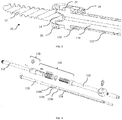
- Fig. 1-12 show screwdriver 100 according to a first embodiment of the present disclosure for a robotic screwdriver.
- Screwdriver 100 extends between proximal end 102 and distal end 104.
- Distal end 104 is configured for securing to and engaging a screw, such as pedicle screw 10 shown in Fig. 2 .
- Screwdriver 100 may be used with mono-axial pedicle screws, poly-axial pedicle screws, reduction screws, screws designed for minimally invasive surgeries (MIS screws), and other compatible screws.
- MIS screws minimally invasive surgeries
- Fig. 3 shows poly-axial bone screw 10 having a threaded shaft 12 and a head 14, received within a tulip 20.
- Tulip 20 is designed to receive a stabilizing rod therethrough.
- An inner surface 22 of tulip 20 includes threads 24 that engage with a set screw to secure the stabilizing rod and which are capable of engaging with the screwdriver 100, as described in further detail below.
- screwdriver 100 includes an outer body 108 formed of a proximal body 110, an outer sleeve 112 positioned distally to proximal body 110, and an inner shaft 116.
- Proximal body 110 and outer sleeve 112 each have a longitudinal bore extending completely therethrough along a central axis of each such that the bores share a common axis for receiving inner shaft 116.
- Inner shaft 116 is positioned concentrically within the outer sleeve 112 and proximal body 110.
- screwdriver 100 includes engaging end 130 for engaging screw 10.
- Outer sleeve 112 includes external threaded portion 132 configured to thread into corresponding threads 24 on inner surface 22 of the tulip 20 of screw 10.
- Shaft 116 includes driving member 138 for engagement within a corresponding opening of head 14 of screw 10 that resides within tulip 20.
- Driving member 138 may be hexagonally shaped or another non-circular shape and is designed to torque shaft 12 to advance screw 10 into bone. With shaft 116 positioned within outer sleeve 112 during use, driving member 138 extends farther distally than threaded portion 132 of the outer sleeve.
- Shaft 116 further includes at least two opposing lateral projections 136 abutted against threaded portion 132 of outer sleeve 112 for being received within tulip 20 of the screw 10, such that it has a non-circular cross section residing within tulip 20. Projections 136 also torque tulip 20 during advancement of screw 10 into bone so that screw 10 rotates all at once.
- Screwdriver 100 includes an improved locking mechanism 135 that allows screwdriver 100 to automatically lock so that when screw 10 is threaded onto threaded portion 132 of outer sleeve 112, the screw cannot inadvertently loosen from outer sleeve 112 during use of screwdriver 100.
- this locking mechanism enables efficient locking and unlocking by a robotic device during operation.
- Locking mechanism 135 includes a collar 140 positioned around a ratchet assembly 143 for facilitating the locking and unlocking of screwdriver 100.
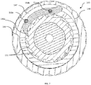
- Collar 140 defines a bore extending therethrough so that inner shaft 116 is positioned therethrough. Collar 140 is rotatable in opposing first and second directions relative to outer body 108, i.e. outer sleeve 112 and proximal body 110. In the illustrated embodiment, collar 140 is designed to be rotated in the first direction, e.g. clockwise direction, to lock screwdriver 100 and in the second direction, e.g. counter-clockwise direction, to unlock screwdriver 100. Collar 140 includes an outer textured surface 142 for ease of gripping and rotating during use. Inner surface 144 of collar 140 is formed as a cam surface with a relief portion 147 to engage ratchet assembly 143, as described in further detail below.
- Ratchet assembly 143 includes spline member 150 formed on an external surface of proximal body 110.
- Spline member 150 defines a bore extending therethrough so that shaft 116 extends through the spline member.
- shaft 116 is keyed, i.e. noncircular in cross section, such that it includes at least one flat surface 118 along a length of the shaft to prevent rotation of the shaft relative to spline member 150.
- Spline member 150 is similarly keyed and includes a plurality of axial splines or teeth 151, each being angled relative to a plane normal to the external surface of proximal body 110.
- Ratchet assembly 143 further includes pawl 146 positioned within opening 119 of outer sleeve 112.
- Pawl 146 includes a ramped portion 146a shaped as a hooked end and sized to correspond to the angled shape of splines 151 so that pawl 146 can engage splines 151 and a tail at an opposing end of the pawl. Pawl 146 may have a sinusoidal shape or an arc shape.
- Ratchet assembly 143 further includes a leaf spring 153a for biasing pawl 146 to engage spline member 150. Spring 153a is positioned on an upper surface of pawl 146 and a pin 153b is positioned through the body of the pawl to maintain the position of the pawl.
- collar 140 can be rotated in the first, clockwise, direction so that threaded portion 132 of outer sleeve 112 mates with the corresponding internal threads 24 of tulip 20 to thread screw 10 onto screwdriver 100.
- spring 153a applies a force on pawl 146 to engage pawl 146 with spline member 150 to mechanically connect the rotation of the outer sleeve 112 and the spline member 150 of the proximal body 110.
- inner shaft 116 is rotationally fixed to spline member 150, due to the keyed surface of inner shaft 116, outer sleeve 112 is mechanically connected with inner shaft 116 in this configuration, shown in Figs. 6 and 7 .
- pawl 143 and spline member 150 places the screwdriver 100 in a locked condition so that outer body 108 and inner shaft 116 are in mechanical engagement with each other to prevent accidental or inadvertent unthreading of threaded portion 132 of outer sleeve 112 from threads 24 of tulip 20.
- ratchet assembly 143 and thus screwdriver 100 is in the engaged or locked condition, the screw can then be advanced into bone without loosening from the screwdriver.
- Screwdriver 100 further includes a limiting feature to prevent the collar from rotating further than necessary.
- locking mechanism 135 further includes ring 145 that has a protrusion 148 projecting inward toward a center of the ring 145 and received within groove 113 of outer sleeve 112 to prevent ring 145 from rotating relative to the outer sleeve 112 when ring 145 is disposed about outer sleeve 112.
- Collar 140 includes projection 141 projecting in a proximal direction from a proximal end of collar 140. Projection 141 is sized and shaped to be received within a cut-out portion 149 on ring 145. The rotational movement of projection 141 is limited to the width of cut-out portion 149, which limits the amount that collar 140 can rotate once it has transitioned to the desired condition, i.e. locked or unlocked.
- screwdriver 100 and locking mechanism 135 allow for relatively easy and intuitive unthreading of the screwdriver from screw 10 to remove the screwdriver after the screw has been implanted within bone.
- Screwdriver 100 further includes screw selection mechanism 170 which allows the screwdriver to be used in conjunction with standard size pedicle screws, such as screw 10, and screws 10' that have elongated tulips or tabs 20' connected to the tulip that extend proximally therefrom such as reduction screws or MIS screws, shown in Fig. 12 .
- standard size pedicle screws such as screw 10
- screws 10' that have elongated tulips or tabs 20' connected to the tulip that extend proximally therefrom such as reduction screws or MIS screws, shown in Fig. 12 .
- Screw selection mechanism 170 is housed within outer sleeve 112 and allows outer sleeve 112 to move axially relative to inner shaft 116 to change the longitudinal position of outer sleeve 112 relative to driving member 138 of inner shaft 116.
- inner shaft 116 has two zones along its length of reduced diameter.
- the first region of reduced diameter is region 119a which is positioned proximal to the second region 119b of reduced diameter of the shaft.
- the regions are separated by a region of relatively larger diameter 119c, which allows the two regions to be formed.
- Screw selection mechanism 170 includes button 173 received within opening 115 of outer sleeve 112.
- Button 173 has a generally rectangular shape having two opposing rounded upper and lower surfaces.
- Button 173 further defines through-opening 176 for receiving inner shaft 116.
- Button 173 includes groove extending from proximal surface 178 to distal surface 179 that is open to through-opening 176.
- button 173 is biased by spring 180 so that the spring maintains secure engagement with shaft 116 extending through button 173, and in the actuated condition, when button 173 is depressed by a user, spring 180 is compressed and outer sleeve 112 can be moved along its longitudinal axis.
- outer sleeve 112 is positioned to receive a standard size screw. If rather than a standard size screw, a reduction screw is being used, the user may actuate screw selection mechanism 170 by depressing button 173 and sliding outer sleeve 112 in the proximal direction to region 119a so that the distance from the distal end of outer sleeve 112 to the distal end of inner shaft 116 is greater.
- Screwdriver 100 is designed for use in robot-assisted surgery.
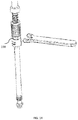
- a robotic device 200 including a robotic arm with a rotatable end effector 210 coupled to the end of the robotic arm may interface with a robotic unit coupler 192 positioned on proximal end 102 of screwdriver 100.
- Robotic coupler 192 includes at least one tab 194 for transmitting torque to the screwdriver.
- Proximal body 110 includes shoulder 111 that has a relatively greater diameter to prevent run out of the driver during rotation. With inner shaft 116 positioned within outer body 108, the end effector 210 transmits torque to inner shaft 116 to advance the screw in bone. Though, in such a case, a surgeon or other user would engage locking mechanism 135 manually to lock the screw to the screwdriver prior to the use of the robot for screw advancement.
- Robotic systems may be used throughout the pre-operative and intra-operative stages of the surgery.
- preoperative planning for surgeries may include determining the bone quality in order to optimize bone preparation.
- Bone quality information such as bone density or elastic modulus
- preoperative scans e.g. CT scans.
- the bone quality data can be used to determine optimal properties for effective implant engagement. Examples of such methods are found in U.S. Patent No. 10,166,109 to Ferko, filed on Sept. 18, 2014 , entitled "Patient Specific Bone Preparation for Consistent Effective Fixation Feature Engagement," U.S. Patent Application Publication No. 2015/0119987 to Davignon et al., filed on Oct.
- robotic systems and methods may be used in the performance of spine surgeries to place implants in the patient's spine as in, for example, U.S. Patent Application Publication No. 2018/0325608 to Kang et al., filed on May 10, 2018 , entitled “Robotic Spine Surgery System and Methods," the disclosure of which is hereby incorporated by reference herein in its entirety.
- the robotic system generally includes a manipulator and a navigation system to track a surgical tool relative to a patient's spine.
- the surgical tool may be manually and/or autonomously controlled. Examples of robotic systems and methods that employ both a manual and a semi-autonomous are described in U.S. Pat. No. 9,566,122 to Bowling et al., filed on Jun.
- a robotic controller may be configured to control the robotic arm to provide haptic feedback to the user via the robotic arm.
- This haptic feedback helps to constrain or inhibit the surgeon from manually moving the screwdriver 100 beyond predefined virtual boundaries associated with the surgical procedure.
- Such a haptic feedback system and associated haptic objects that define the virtual boundaries are described in, for example, U.S. Patent No. 9,002,426 to Quaid et al., filed on June 23, 2008 , entitled “Haptic Guidance System and Method," and U.S. Pat. No. 8,010,180 to Quaid et al., filed on Dec. 21, 2012 , entitled “Systems and Methods for Haptic Control of a Surgical Tool," and U.S. Patent No. 10,098,704 to Bowling et al., filed on May 18, 2016 , entitled “System and Method for Manipulating an Anatomy,” each of which is hereby incorporated by reference herein in its entirety.
- a tool center point (TCP) of a surgical tool is brought to within a predefined distance of a starting point of a line haptic object that provides the desired trajectory.
- TCP tool center point
- actuation of an input causes the robotic arm to autonomously align and position the surgical tool on the desired trajectory.
- the robotic system may effectively hold the rotational axis of the surgical tool on the desired trajectory by tracking movement of the patient and autonomously adjusting the robotic arm as needed to keep the rotational axis on the desired trajectory.
- screwdriver 100 includes hex member 198 on collar 140 or adjacent thereto to release the engagement of the ratcheting assembly 143 with the use of a wrench in the event there is an internal jam or the surgeon cannot otherwise effectively turn the collar counter-clockwise.
- Screwdriver 600 includes locking mechanism 635 with internally threaded ring 640 which engages external threads on threaded portion 617 of outer sleeve 612.
- Threaded portion 617 is formed of cantilever tabs or flexible fingers 619 extending in an axial direction on threaded portion 617 and being separated along the circumference of outer sleeve 612.
- first direction i.e. clockwise
- flexible fingers 619 flex inwardly toward the inner shaft to lock the inner shaft relative to outer sleeve 612 so that they are rotatably fixed to each other.
- second direction i.e. counter-clockwise
- flexible fingers 619 flex outwardly away from the inner shaft to unlock the inner shaft and outer sleeve 612.
- screwdriver 700 shown in Figs. 17 and 18 , includes locking mechanism 735 that includes collar 740 that includes an internal cam surface.
- Outer sleeve 712 includes cantilevered ratchet fingers 719 extending transverse to the longitudinal axis of outer sleeve 712.
- Each ratchet finger 719 includes a tooth or projection (not shown) that extends inwardly toward spline member 750 and inner shaft 716.
- the cam surface engages the ratchet finger 719 and pushes it toward spline member 750 so that the tooth engages spline member 750 to mechanically lock the inner shaft and outer sleeve 712.
- FIGs. 19-23 show screwdriver 800 according to another embodiment of the present disclosure.
- Screwdriver 800 includes many similar features to screwdriver 100, the similar features of which will not be described again herein.
- screwdriver 800 At its proximal end 102, screwdriver 800 includes two torque tabs 894 for engagement with a robotic end effector, which imparts force thereon to torque the screwdriver. Further, locking mechanism includes c-clip spring 853a for biasing pawl 846 to mechanically lock inner shaft 816 and outer sleeve 812. Moreover, locking mechanism 835 includes friction drag ring 854 and to prevent unintentional unlocking or unlocking of the locking mechanism.
- Fig. 22 shows screwdriver 800 in the locked position with pawl 846 engaged with splines 844
- Fig. 23 shows screwdriver 800 in the unlocked position with pawl 846 disengaged from splines 844.
- distal end 804 may be adapted to conform to various types of spinal screws.
- Fig. 24 shows screwdriver 800a for use with a standard pedicle screws, screwdriver 800b for use with minimally invasive (MIS) percutaneous pedicle screws, screwdriver 800c for use with a top-loading polyaxial pedicle screw, screwdriver 800d for break-off extension tabs for minimally invasive surgery, and screwdriver 800e for use with low profile pedicle screws.
- Example pedicle screws are those offered by Stryker under the names Xia 3, ES2, Everest, Everest XT and Xia 4.5, but these screwdrivers can be utilized with other existing screws.
Landscapes
- Health & Medical Sciences (AREA)
- Orthopedic Medicine & Surgery (AREA)
- Neurology (AREA)
- Surgery (AREA)
- Life Sciences & Earth Sciences (AREA)
- Engineering & Computer Science (AREA)
- Heart & Thoracic Surgery (AREA)
- Biomedical Technology (AREA)
- Nuclear Medicine, Radiotherapy & Molecular Imaging (AREA)
- Medical Informatics (AREA)
- Molecular Biology (AREA)
- Animal Behavior & Ethology (AREA)
- General Health & Medical Sciences (AREA)
- Public Health (AREA)
- Veterinary Medicine (AREA)
- Mechanical Engineering (AREA)
- Surgical Instruments (AREA)
- Details Of Spanners, Wrenches, And Screw Drivers And Accessories (AREA)
Applications Claiming Priority (1)
| Application Number | Priority Date | Filing Date | Title |
|---|---|---|---|
| US201962813915P | 2019-03-05 | 2019-03-05 |
Publications (3)
| Publication Number | Publication Date |
|---|---|
| EP3705069A2 true EP3705069A2 (de) | 2020-09-09 |
| EP3705069A3 EP3705069A3 (de) | 2020-09-23 |
| EP3705069B1 EP3705069B1 (de) | 2023-02-22 |
Family
ID=69770605
Family Applications (1)
| Application Number | Title | Priority Date | Filing Date |
|---|---|---|---|
| EP20160901.3A Active EP3705069B1 (de) | 2019-03-05 | 2020-03-04 | Automatischer ratschen-schraubendreher |
Country Status (2)
| Country | Link |
|---|---|
| US (1) | US11618135B2 (de) |
| EP (1) | EP3705069B1 (de) |
Families Citing this family (9)
| Publication number | Priority date | Publication date | Assignee | Title |
|---|---|---|---|---|
| US11065065B2 (en) * | 2019-02-22 | 2021-07-20 | Warsaw Orthopedic, Inc. | Spinal implant system and methods of use |
| US11707311B2 (en) * | 2020-02-05 | 2023-07-25 | Adam Isaac Lewis | Bone fastener and driver with retaining features |
| US11627998B2 (en) * | 2020-12-11 | 2023-04-18 | Warsaw Orthopedic, Inc. | Head position and driver combination instrument |
| US11596452B2 (en) * | 2021-02-02 | 2023-03-07 | Medos International Sarl | Surgical instruments and methods for selectively coupling to an object |
| EP4389054B1 (de) * | 2021-06-02 | 2025-09-10 | Shanghai Droidsurg Medical Co., Ltd | Betriebssystem für knochengewebe |
| DE102021122528B3 (de) * | 2021-08-31 | 2022-12-22 | Maku Ag | Schlüsselaufsatz |
| US12025188B1 (en) * | 2021-10-01 | 2024-07-02 | Agility Robotics, Inc. | Actuator encoder assembly method and apparatus |
| US12053860B2 (en) * | 2022-01-04 | 2024-08-06 | Yu-Hua Ou | Driver tool with rotatable torque limiting sleeve |
| US11787026B2 (en) * | 2022-01-04 | 2023-10-17 | Yu-Hua Ou | Ratchet tool |
Citations (13)
| Publication number | Priority date | Publication date | Assignee | Title |
|---|---|---|---|---|
| US8010180B2 (en) | 2002-03-06 | 2011-08-30 | Mako Surgical Corp. | Haptic guidance system and method |
| US20140180290A1 (en) | 2012-12-21 | 2014-06-26 | Mako Surgical Corp. | Systems and methods for haptic control of a surgical tool |
| US20150119987A1 (en) | 2013-10-28 | 2015-04-30 | Stryker Corporation | Implant design using heterogeneous bone properties and probabilistic tools to determine optimal geometries for fixation features |
| US9119655B2 (en) | 2012-08-03 | 2015-09-01 | Stryker Corporation | Surgical manipulator capable of controlling a surgical instrument in multiple modes |
| US9566122B2 (en) | 2012-08-03 | 2017-02-14 | Stryker Corporation | Robotic system and method for transitioning between operating modes |
| US20170128136A1 (en) | 2015-11-11 | 2017-05-11 | Mako Surgical Corp. | Robotic system and method for backdriving the same |
| US20180168750A1 (en) | 2016-12-16 | 2018-06-21 | Mako Surgical Corp. | Techniques for modifying tool operation in a surgical robotic system based on comparing actual and commanded states of the tool relative to a surgical site |
| US10028788B2 (en) | 2012-12-31 | 2018-07-24 | Mako Surgical Corp. | System for image-based robotic surgery |
| US10070928B2 (en) | 2015-07-01 | 2018-09-11 | Mako Surgical Corp. | Implant placement planning |
| US10098704B2 (en) | 2015-05-19 | 2018-10-16 | Mako Surgical Corp. | System and method for manipulating an anatomy |
| US10117713B2 (en) | 2015-07-01 | 2018-11-06 | Mako Surgical Corp. | Robotic systems and methods for controlling a tool removing material from a workpiece |
| US20180325608A1 (en) | 2017-05-10 | 2018-11-15 | Mako Surgical Corp. | Robotic Spine Surgery System And Methods |
| US10166109B2 (en) | 2013-09-18 | 2019-01-01 | Stryker Corporation | Patient specific bone preparation for consistent effective fixation feature engagement |
Family Cites Families (36)
| Publication number | Priority date | Publication date | Assignee | Title |
|---|---|---|---|---|
| US366439A (en) * | 1887-07-12 | Reversible screw-driver | ||
| US3584667A (en) | 1966-09-19 | 1971-06-15 | Textron Inc | Coupling arrangement and tools for same |
| US4197889A (en) | 1978-10-20 | 1980-04-15 | C. Hager & Sons Hinge Manufacturing Company | Security screw, driver therefor, and process |
| US5139499A (en) | 1989-02-06 | 1992-08-18 | American Cyanamid Company | Screw and driver |
| US5171117A (en) | 1991-10-16 | 1992-12-15 | Textron Inc. | Fastener with multilobular internal recess and tool entry ramps |
| US5946988A (en) | 1992-02-27 | 1999-09-07 | Howmedica Gmbh | Tool for driving pedicle screws |
| JPH0737805B2 (ja) | 1992-11-17 | 1995-04-26 | 有限会社新城製作所 | 凹部付きねじ及びそのドライバビット |
| US5649931A (en) | 1996-01-16 | 1997-07-22 | Zimmer, Inc. | Orthopaedic apparatus for driving and/or removing a bone screw |
| US5836430A (en) | 1997-01-13 | 1998-11-17 | Maxtech, Inc. | Ratchet mechanism for screwdrivers and the like |
| US6554834B1 (en) | 1999-10-07 | 2003-04-29 | Stryker Spine | Slotted head pedicle screw assembly |
| US6244139B1 (en) * | 2000-06-20 | 2001-06-12 | Daniel Huang | Adjustable shifter for controlling the racing of a slideable ratchet shank |
| US6488681B2 (en) | 2001-01-05 | 2002-12-03 | Stryker Spine S.A. | Pedicle screw assembly |
| US6974460B2 (en) | 2001-09-14 | 2005-12-13 | Stryker Spine | Biased angulation bone fixation assembly |
| FR2831049B1 (fr) | 2001-10-18 | 2004-08-13 | Ldr Medical | Plaque pour dispositif d'osteosynthese et procede de premontage |
| ES2629431T3 (es) | 2002-10-30 | 2017-08-09 | Zimmer Spine, Inc. | Sistema de estabilización espinal por inserción |
| US7588575B2 (en) | 2003-10-21 | 2009-09-15 | Innovative Spinal Technologies | Extension for use with stabilization systems for internal structures |
| US8152810B2 (en) | 2004-11-23 | 2012-04-10 | Jackson Roger P | Spinal fixation tool set and method |
| US7771459B2 (en) | 2004-06-07 | 2010-08-10 | Degima Gmbh | Fastener having torque optimized head |
| US7311022B2 (en) | 2004-08-16 | 2007-12-25 | Snap-On Incorporated | Retention socket |
| US7691129B2 (en) | 2004-10-27 | 2010-04-06 | Felix Brent A | Spinal stabilizing system |
| WO2006057837A1 (en) | 2004-11-23 | 2006-06-01 | Jackson Roger P | Spinal fixation tool attachment structure |
| EP2043528A2 (de) | 2006-06-09 | 2009-04-08 | Zimmer Spine, Inc. | Verfahren und gerät für den zugang zur und/oder die behandlung der wirbelsäule |
| BRPI0716665A2 (pt) | 2006-08-17 | 2013-12-10 | Synthes Gmbh | Acionador para inserir um parafuso para osso |
| US8231635B2 (en) | 2007-01-18 | 2012-07-31 | Stryker Spine | Polyaxial screwdriver for a pedicle screw system |
| US8845652B2 (en) | 2007-02-27 | 2014-09-30 | Warsaw Orthopedic, Inc. | Surgical driver |
| US20090264895A1 (en) | 2008-04-22 | 2009-10-22 | Warsaw Orthopedic, Inc. | Systems and methods for implanting a bone fastener and delivering a bone filling material |
| US8545505B2 (en) * | 2010-01-15 | 2013-10-01 | Pioneer Surgical Technology, Inc. | Low friction rod persuader |
| DE102010029692B4 (de) | 2010-06-04 | 2016-07-21 | Swg Schraubenwerk Gaisbach Gmbh & Co Kg | Drehantriebsausbildung |
| US8142437B2 (en) | 2010-06-18 | 2012-03-27 | Spine Wave, Inc. | System for percutaneously fixing a connecting rod to a spine |
| US8784431B1 (en) | 2012-06-11 | 2014-07-22 | Choice Spine, Lp | Medical screwdriver |
| US9532814B2 (en) | 2013-03-14 | 2017-01-03 | Globus Medical, Inc. | Instruments for use during spine surgery |
| US9433445B2 (en) * | 2013-03-14 | 2016-09-06 | DePuy Synthes Products, Inc. | Bone anchors and surgical instruments with integrated guide tips |
| DE102013113401A1 (de) | 2013-12-03 | 2015-06-03 | Adolf Würth GmbH & Co. KG | Schraube und Antriebselement mit Fase |
| EP2932929B1 (de) | 2014-04-15 | 2017-02-08 | Biedermann Technologies GmbH & Co. KG | Schraubelement zur Verwendung in der spinalen, orthopädischen oder traumatologischen Chirurgie und System mit solch einem Schraubelement und daran angepassten Schraubendreher |
| US9821442B2 (en) | 2015-10-19 | 2017-11-21 | Bryce Fastener Company, Inc. | Methods and apparatus for an enhanced driving bit |
| US10730167B2 (en) | 2017-07-19 | 2020-08-04 | Zimmer, Inc. | Disposable surgical screwdriver |
-
2020
- 2020-03-04 EP EP20160901.3A patent/EP3705069B1/de active Active
- 2020-03-04 US US16/809,065 patent/US11618135B2/en active Active
Patent Citations (14)
| Publication number | Priority date | Publication date | Assignee | Title |
|---|---|---|---|---|
| US8010180B2 (en) | 2002-03-06 | 2011-08-30 | Mako Surgical Corp. | Haptic guidance system and method |
| US9002426B2 (en) | 2002-03-06 | 2015-04-07 | Mako Surgical Corp. | Haptic guidance system and method |
| US9119655B2 (en) | 2012-08-03 | 2015-09-01 | Stryker Corporation | Surgical manipulator capable of controlling a surgical instrument in multiple modes |
| US9566122B2 (en) | 2012-08-03 | 2017-02-14 | Stryker Corporation | Robotic system and method for transitioning between operating modes |
| US20140180290A1 (en) | 2012-12-21 | 2014-06-26 | Mako Surgical Corp. | Systems and methods for haptic control of a surgical tool |
| US10028788B2 (en) | 2012-12-31 | 2018-07-24 | Mako Surgical Corp. | System for image-based robotic surgery |
| US10166109B2 (en) | 2013-09-18 | 2019-01-01 | Stryker Corporation | Patient specific bone preparation for consistent effective fixation feature engagement |
| US20150119987A1 (en) | 2013-10-28 | 2015-04-30 | Stryker Corporation | Implant design using heterogeneous bone properties and probabilistic tools to determine optimal geometries for fixation features |
| US10098704B2 (en) | 2015-05-19 | 2018-10-16 | Mako Surgical Corp. | System and method for manipulating an anatomy |
| US10070928B2 (en) | 2015-07-01 | 2018-09-11 | Mako Surgical Corp. | Implant placement planning |
| US10117713B2 (en) | 2015-07-01 | 2018-11-06 | Mako Surgical Corp. | Robotic systems and methods for controlling a tool removing material from a workpiece |
| US20170128136A1 (en) | 2015-11-11 | 2017-05-11 | Mako Surgical Corp. | Robotic system and method for backdriving the same |
| US20180168750A1 (en) | 2016-12-16 | 2018-06-21 | Mako Surgical Corp. | Techniques for modifying tool operation in a surgical robotic system based on comparing actual and commanded states of the tool relative to a surgical site |
| US20180325608A1 (en) | 2017-05-10 | 2018-11-15 | Mako Surgical Corp. | Robotic Spine Surgery System And Methods |
Also Published As
| Publication number | Publication date |
|---|---|
| EP3705069B1 (de) | 2023-02-22 |
| EP3705069A3 (de) | 2020-09-23 |
| US11618135B2 (en) | 2023-04-04 |
| US20200282530A1 (en) | 2020-09-10 |
Similar Documents
| Publication | Publication Date | Title |
|---|---|---|
| EP3705069B1 (de) | Automatischer ratschen-schraubendreher | |
| US12521127B2 (en) | Bone screws, instrumentation, and methods of using of same | |
| EP3982854B1 (de) | Schraubeneindreherinstrumente | |
| US8123785B2 (en) | Minimally invasive spinal stabilization system | |
| US7226453B2 (en) | Instrument for inserting, adjusting and removing pedicle screws and other orthopedic implants | |
| EP2560564B1 (de) | Instrumentensätze für wirbelchirurgie | |
| EP3982855B1 (de) | Schraubeneinführerinstrumente | |
| US11471198B2 (en) | Implant driver | |
| JP6072012B2 (ja) | 椎骨整列特徴を含む低侵襲的脊椎固定システム | |
| US20250352250A1 (en) | Rod reduction assemblies and related methods | |
| US20130331892A1 (en) | Minimally invasive instrument set, devices and related methods | |
| WO2014140132A1 (en) | Driver assembly with guidewire control mechanism | |
| US12426927B2 (en) | Split tower for a bone anchor | |
| US12064124B2 (en) | Tools for insertion of a spinal implant and methods of using same | |
| US11559337B2 (en) | Expended tab reinforcement sleeve | |
| EP4011306B1 (de) | Schraubeneinführinstrument | |
| EP2288303B1 (de) | Minimal invasives wirbelsäulen-stabilisierungssystem | |
| US11672581B2 (en) | Powered retaining screwdriver | |
| US12605190B2 (en) | Pedicle screw stabilization systems and instruments | |
| US20250241662A1 (en) | Guidewire-capturing surgical instrument | |
| US20230190253A1 (en) | Anterior cervical disc distractor |
Legal Events
| Date | Code | Title | Description |
|---|---|---|---|
| PUAI | Public reference made under article 153(3) epc to a published international application that has entered the european phase |
Free format text: ORIGINAL CODE: 0009012 |
|
| STAA | Information on the status of an ep patent application or granted ep patent |
Free format text: STATUS: REQUEST FOR EXAMINATION WAS MADE |
|
| PUAL | Search report despatched |
Free format text: ORIGINAL CODE: 0009013 |
|
| 17P | Request for examination filed |
Effective date: 20200304 |
|
| AK | Designated contracting states |
Kind code of ref document: A2 Designated state(s): AL AT BE BG CH CY CZ DE DK EE ES FI FR GB GR HR HU IE IS IT LI LT LU LV MC MK MT NL NO PL PT RO RS SE SI SK SM TR |
|
| AX | Request for extension of the european patent |
Extension state: BA ME |
|
| AK | Designated contracting states |
Kind code of ref document: A3 Designated state(s): AL AT BE BG CH CY CZ DE DK EE ES FI FR GB GR HR HU IE IS IT LI LT LU LV MC MK MT NL NO PL PT RO RS SE SI SK SM TR |
|
| AX | Request for extension of the european patent |
Extension state: BA ME |
|
| RIC1 | Information provided on ipc code assigned before grant |
Ipc: A61B 17/88 20060101ALI20200819BHEP Ipc: A61B 17/70 20060101AFI20200819BHEP |
|
| GRAP | Despatch of communication of intention to grant a patent |
Free format text: ORIGINAL CODE: EPIDOSNIGR1 |
|
| STAA | Information on the status of an ep patent application or granted ep patent |
Free format text: STATUS: GRANT OF PATENT IS INTENDED |
|
| INTG | Intention to grant announced |
Effective date: 20220909 |
|
| GRAS | Grant fee paid |
Free format text: ORIGINAL CODE: EPIDOSNIGR3 |
|
| GRAA | (expected) grant |
Free format text: ORIGINAL CODE: 0009210 |
|
| STAA | Information on the status of an ep patent application or granted ep patent |
Free format text: STATUS: THE PATENT HAS BEEN GRANTED |
|
| AK | Designated contracting states |
Kind code of ref document: B1 Designated state(s): AL AT BE BG CH CY CZ DE DK EE ES FI FR GB GR HR HU IE IS IT LI LT LU LV MC MK MT NL NO PL PT RO RS SE SI SK SM TR |
|
| REG | Reference to a national code |
Ref country code: GB Ref legal event code: FG4D |
|
| REG | Reference to a national code |
Ref country code: CH Ref legal event code: EP |
|
| REG | Reference to a national code |
Ref country code: AT Ref legal event code: REF Ref document number: 1549022 Country of ref document: AT Kind code of ref document: T Effective date: 20230315 Ref country code: IE Ref legal event code: FG4D |
|
| REG | Reference to a national code |
Ref country code: DE Ref legal event code: R096 Ref document number: 602020008179 Country of ref document: DE |
|
| REG | Reference to a national code |
Ref country code: LT Ref legal event code: MG9D |
|
| P01 | Opt-out of the competence of the unified patent court (upc) registered |
Effective date: 20230522 |
|
| REG | Reference to a national code |
Ref country code: NL Ref legal event code: MP Effective date: 20230222 |
|
| REG | Reference to a national code |
Ref country code: AT Ref legal event code: MK05 Ref document number: 1549022 Country of ref document: AT Kind code of ref document: T Effective date: 20230222 |
|
| PG25 | Lapsed in a contracting state [announced via postgrant information from national office to epo] |
Ref country code: NL Free format text: LAPSE BECAUSE OF FAILURE TO SUBMIT A TRANSLATION OF THE DESCRIPTION OR TO PAY THE FEE WITHIN THE PRESCRIBED TIME-LIMIT Effective date: 20230222 Ref country code: LV Free format text: LAPSE BECAUSE OF FAILURE TO SUBMIT A TRANSLATION OF THE DESCRIPTION OR TO PAY THE FEE WITHIN THE PRESCRIBED TIME-LIMIT Effective date: 20230222 Ref country code: LT Free format text: LAPSE BECAUSE OF FAILURE TO SUBMIT A TRANSLATION OF THE DESCRIPTION OR TO PAY THE FEE WITHIN THE PRESCRIBED TIME-LIMIT Effective date: 20230222 Ref country code: HR Free format text: LAPSE BECAUSE OF FAILURE TO SUBMIT A TRANSLATION OF THE DESCRIPTION OR TO PAY THE FEE WITHIN THE PRESCRIBED TIME-LIMIT Effective date: 20230222 Ref country code: ES Free format text: LAPSE BECAUSE OF FAILURE TO SUBMIT A TRANSLATION OF THE DESCRIPTION OR TO PAY THE FEE WITHIN THE PRESCRIBED TIME-LIMIT Effective date: 20230222 Ref country code: AT Free format text: LAPSE BECAUSE OF FAILURE TO SUBMIT A TRANSLATION OF THE DESCRIPTION OR TO PAY THE FEE WITHIN THE PRESCRIBED TIME-LIMIT Effective date: 20230222 Ref country code: RS Free format text: LAPSE BECAUSE OF FAILURE TO SUBMIT A TRANSLATION OF THE DESCRIPTION OR TO PAY THE FEE WITHIN THE PRESCRIBED TIME-LIMIT Effective date: 20230222 Ref country code: PT Free format text: LAPSE BECAUSE OF FAILURE TO SUBMIT A TRANSLATION OF THE DESCRIPTION OR TO PAY THE FEE WITHIN THE PRESCRIBED TIME-LIMIT Effective date: 20230622 Ref country code: NO Free format text: LAPSE BECAUSE OF FAILURE TO SUBMIT A TRANSLATION OF THE DESCRIPTION OR TO PAY THE FEE WITHIN THE PRESCRIBED TIME-LIMIT Effective date: 20230522 |
|
| PG25 | Lapsed in a contracting state [announced via postgrant information from national office to epo] |
Ref country code: SE Free format text: LAPSE BECAUSE OF FAILURE TO SUBMIT A TRANSLATION OF THE DESCRIPTION OR TO PAY THE FEE WITHIN THE PRESCRIBED TIME-LIMIT Effective date: 20230222 Ref country code: PL Free format text: LAPSE BECAUSE OF FAILURE TO SUBMIT A TRANSLATION OF THE DESCRIPTION OR TO PAY THE FEE WITHIN THE PRESCRIBED TIME-LIMIT Effective date: 20230222 Ref country code: IS Free format text: LAPSE BECAUSE OF FAILURE TO SUBMIT A TRANSLATION OF THE DESCRIPTION OR TO PAY THE FEE WITHIN THE PRESCRIBED TIME-LIMIT Effective date: 20230622 Ref country code: GR Free format text: LAPSE BECAUSE OF FAILURE TO SUBMIT A TRANSLATION OF THE DESCRIPTION OR TO PAY THE FEE WITHIN THE PRESCRIBED TIME-LIMIT Effective date: 20230523 Ref country code: FI Free format text: LAPSE BECAUSE OF FAILURE TO SUBMIT A TRANSLATION OF THE DESCRIPTION OR TO PAY THE FEE WITHIN THE PRESCRIBED TIME-LIMIT Effective date: 20230222 |
|
| PG25 | Lapsed in a contracting state [announced via postgrant information from national office to epo] |
Ref country code: SM Free format text: LAPSE BECAUSE OF FAILURE TO SUBMIT A TRANSLATION OF THE DESCRIPTION OR TO PAY THE FEE WITHIN THE PRESCRIBED TIME-LIMIT Effective date: 20230222 Ref country code: RO Free format text: LAPSE BECAUSE OF FAILURE TO SUBMIT A TRANSLATION OF THE DESCRIPTION OR TO PAY THE FEE WITHIN THE PRESCRIBED TIME-LIMIT Effective date: 20230222 Ref country code: EE Free format text: LAPSE BECAUSE OF FAILURE TO SUBMIT A TRANSLATION OF THE DESCRIPTION OR TO PAY THE FEE WITHIN THE PRESCRIBED TIME-LIMIT Effective date: 20230222 Ref country code: DK Free format text: LAPSE BECAUSE OF FAILURE TO SUBMIT A TRANSLATION OF THE DESCRIPTION OR TO PAY THE FEE WITHIN THE PRESCRIBED TIME-LIMIT Effective date: 20230222 Ref country code: CZ Free format text: LAPSE BECAUSE OF FAILURE TO SUBMIT A TRANSLATION OF THE DESCRIPTION OR TO PAY THE FEE WITHIN THE PRESCRIBED TIME-LIMIT Effective date: 20230222 |
|
| REG | Reference to a national code |
Ref country code: CH Ref legal event code: PL |
|
| REG | Reference to a national code |
Ref country code: DE Ref legal event code: R097 Ref document number: 602020008179 Country of ref document: DE |
|
| PG25 | Lapsed in a contracting state [announced via postgrant information from national office to epo] |
Ref country code: SK Free format text: LAPSE BECAUSE OF FAILURE TO SUBMIT A TRANSLATION OF THE DESCRIPTION OR TO PAY THE FEE WITHIN THE PRESCRIBED TIME-LIMIT Effective date: 20230222 |
|
| REG | Reference to a national code |
Ref country code: BE Ref legal event code: MM Effective date: 20230331 |
|
| PG25 | Lapsed in a contracting state [announced via postgrant information from national office to epo] |
Ref country code: LU Free format text: LAPSE BECAUSE OF NON-PAYMENT OF DUE FEES Effective date: 20230304 |
|
| PLBE | No opposition filed within time limit |
Free format text: ORIGINAL CODE: 0009261 |
|
| STAA | Information on the status of an ep patent application or granted ep patent |
Free format text: STATUS: NO OPPOSITION FILED WITHIN TIME LIMIT |
|
| PG25 | Lapsed in a contracting state [announced via postgrant information from national office to epo] |
Ref country code: MC Free format text: LAPSE BECAUSE OF FAILURE TO SUBMIT A TRANSLATION OF THE DESCRIPTION OR TO PAY THE FEE WITHIN THE PRESCRIBED TIME-LIMIT Effective date: 20230222 |
|
| REG | Reference to a national code |
Ref country code: IE Ref legal event code: MM4A |
|
| 26N | No opposition filed |
Effective date: 20231123 |
|
| PG25 | Lapsed in a contracting state [announced via postgrant information from national office to epo] |
Ref country code: SI Free format text: LAPSE BECAUSE OF FAILURE TO SUBMIT A TRANSLATION OF THE DESCRIPTION OR TO PAY THE FEE WITHIN THE PRESCRIBED TIME-LIMIT Effective date: 20230222 Ref country code: MC Free format text: LAPSE BECAUSE OF FAILURE TO SUBMIT A TRANSLATION OF THE DESCRIPTION OR TO PAY THE FEE WITHIN THE PRESCRIBED TIME-LIMIT Effective date: 20230222 Ref country code: LI Free format text: LAPSE BECAUSE OF NON-PAYMENT OF DUE FEES Effective date: 20230331 Ref country code: IE Free format text: LAPSE BECAUSE OF NON-PAYMENT OF DUE FEES Effective date: 20230304 Ref country code: CH Free format text: LAPSE BECAUSE OF NON-PAYMENT OF DUE FEES Effective date: 20230331 |
|
| PG25 | Lapsed in a contracting state [announced via postgrant information from national office to epo] |
Ref country code: BE Free format text: LAPSE BECAUSE OF NON-PAYMENT OF DUE FEES Effective date: 20230331 |
|
| PG25 | Lapsed in a contracting state [announced via postgrant information from national office to epo] |
Ref country code: IT Free format text: LAPSE BECAUSE OF FAILURE TO SUBMIT A TRANSLATION OF THE DESCRIPTION OR TO PAY THE FEE WITHIN THE PRESCRIBED TIME-LIMIT Effective date: 20230222 |
|
| PG25 | Lapsed in a contracting state [announced via postgrant information from national office to epo] |
Ref country code: BG Free format text: LAPSE BECAUSE OF FAILURE TO SUBMIT A TRANSLATION OF THE DESCRIPTION OR TO PAY THE FEE WITHIN THE PRESCRIBED TIME-LIMIT Effective date: 20230222 |
|
| PG25 | Lapsed in a contracting state [announced via postgrant information from national office to epo] |
Ref country code: BG Free format text: LAPSE BECAUSE OF FAILURE TO SUBMIT A TRANSLATION OF THE DESCRIPTION OR TO PAY THE FEE WITHIN THE PRESCRIBED TIME-LIMIT Effective date: 20230222 |
|
| REG | Reference to a national code |
Ref country code: DE Ref legal event code: R081 Ref document number: 602020008179 Country of ref document: DE Owner name: STRYKER CORPORATION, PORTAGE, US Free format text: FORMER OWNER: K2M, INC., LEESBURG, VA, US Ref country code: DE Ref legal event code: R081 Ref document number: 602020008179 Country of ref document: DE Owner name: VB SPINE US OPCO LLC, WILMINGTON, US Free format text: FORMER OWNER: K2M, INC., LEESBURG, VA, US |
|
| REG | Reference to a national code |
Ref country code: GB Ref legal event code: 732E Free format text: REGISTERED BETWEEN 20250626 AND 20250702 |
|
| PG25 | Lapsed in a contracting state [announced via postgrant information from national office to epo] |
Ref country code: CY Free format text: LAPSE BECAUSE OF FAILURE TO SUBMIT A TRANSLATION OF THE DESCRIPTION OR TO PAY THE FEE WITHIN THE PRESCRIBED TIME-LIMIT; INVALID AB INITIO Effective date: 20200304 |
|
| PG25 | Lapsed in a contracting state [announced via postgrant information from national office to epo] |
Ref country code: HU Free format text: LAPSE BECAUSE OF FAILURE TO SUBMIT A TRANSLATION OF THE DESCRIPTION OR TO PAY THE FEE WITHIN THE PRESCRIBED TIME-LIMIT; INVALID AB INITIO Effective date: 20200304 |
|
| REG | Reference to a national code |
Ref country code: DE Ref legal event code: R081 Ref document number: 602020008179 Country of ref document: DE Owner name: VB SPINE US OPCO LLC, WILMINGTON, US Free format text: FORMER OWNER: STRYKER CORPORATION, PORTAGE, MI, US |
|
| PG25 | Lapsed in a contracting state [announced via postgrant information from national office to epo] |
Ref country code: TR Free format text: LAPSE BECAUSE OF FAILURE TO SUBMIT A TRANSLATION OF THE DESCRIPTION OR TO PAY THE FEE WITHIN THE PRESCRIBED TIME-LIMIT Effective date: 20230222 |
|
| REG | Reference to a national code |
Ref country code: GB Ref legal event code: 732E Free format text: REGISTERED BETWEEN 20251120 AND 20251126 |
|
| PGFP | Annual fee paid to national office [announced via postgrant information from national office to epo] |
Ref country code: FR Payment date: 20251231 Year of fee payment: 7 |
|
| PGFP | Annual fee paid to national office [announced via postgrant information from national office to epo] |
Ref country code: GB Payment date: 20260106 Year of fee payment: 7 |
|
| PGFP | Annual fee paid to national office [announced via postgrant information from national office to epo] |
Ref country code: DE Payment date: 20260102 Year of fee payment: 7 |