EP3704920B1 - Landwirtschaftliches einachsfahrzeug - Google Patents
Landwirtschaftliches einachsfahrzeug Download PDFInfo
- Publication number
- EP3704920B1 EP3704920B1 EP20160954.2A EP20160954A EP3704920B1 EP 3704920 B1 EP3704920 B1 EP 3704920B1 EP 20160954 A EP20160954 A EP 20160954A EP 3704920 B1 EP3704920 B1 EP 3704920B1
- Authority
- EP
- European Patent Office
- Prior art keywords
- axle
- running board
- agricultural
- pendulum
- locating
- Prior art date
- Legal status (The legal status is an assumption and is not a legal conclusion. Google has not performed a legal analysis and makes no representation as to the accuracy of the status listed.)
- Active
Links
Images

Classifications
-
- A—HUMAN NECESSITIES
- A01—AGRICULTURE; FORESTRY; ANIMAL HUSBANDRY; HUNTING; TRAPPING; FISHING
- A01B—SOIL WORKING IN AGRICULTURE OR FORESTRY; PARTS, DETAILS, OR ACCESSORIES OF AGRICULTURAL MACHINES OR IMPLEMENTS, IN GENERAL
- A01B33/00—Tilling implements with rotary driven tools, e.g. in combination with fertiliser distributors or seeders, with grubbing chains, with sloping axles, with driven discs
- A01B33/08—Tools; Details, e.g. adaptations of transmissions or gearings
- A01B33/10—Structural or functional features of the tools ; Theoretical aspects of the cutting action
-
- A—HUMAN NECESSITIES
- A01—AGRICULTURE; FORESTRY; ANIMAL HUSBANDRY; HUNTING; TRAPPING; FISHING
- A01B—SOIL WORKING IN AGRICULTURE OR FORESTRY; PARTS, DETAILS, OR ACCESSORIES OF AGRICULTURAL MACHINES OR IMPLEMENTS, IN GENERAL
- A01B33/00—Tilling implements with rotary driven tools, e.g. in combination with fertiliser distributors or seeders, with grubbing chains, with sloping axles, with driven discs
-
- A—HUMAN NECESSITIES
- A01—AGRICULTURE; FORESTRY; ANIMAL HUSBANDRY; HUNTING; TRAPPING; FISHING
- A01B—SOIL WORKING IN AGRICULTURE OR FORESTRY; PARTS, DETAILS, OR ACCESSORIES OF AGRICULTURAL MACHINES OR IMPLEMENTS, IN GENERAL
- A01B33/00—Tilling implements with rotary driven tools, e.g. in combination with fertiliser distributors or seeders, with grubbing chains, with sloping axles, with driven discs
- A01B33/02—Tilling implements with rotary driven tools, e.g. in combination with fertiliser distributors or seeders, with grubbing chains, with sloping axles, with driven discs with tools on horizontal shaft transverse to direction of travel
-
- A—HUMAN NECESSITIES
- A01—AGRICULTURE; FORESTRY; ANIMAL HUSBANDRY; HUNTING; TRAPPING; FISHING
- A01B—SOIL WORKING IN AGRICULTURE OR FORESTRY; PARTS, DETAILS, OR ACCESSORIES OF AGRICULTURAL MACHINES OR IMPLEMENTS, IN GENERAL
- A01B33/00—Tilling implements with rotary driven tools, e.g. in combination with fertiliser distributors or seeders, with grubbing chains, with sloping axles, with driven discs
- A01B33/16—Tilling implements with rotary driven tools, e.g. in combination with fertiliser distributors or seeders, with grubbing chains, with sloping axles, with driven discs with special additional arrangements
-
- A—HUMAN NECESSITIES
- A01—AGRICULTURE; FORESTRY; ANIMAL HUSBANDRY; HUNTING; TRAPPING; FISHING
- A01B—SOIL WORKING IN AGRICULTURE OR FORESTRY; PARTS, DETAILS, OR ACCESSORIES OF AGRICULTURAL MACHINES OR IMPLEMENTS, IN GENERAL
- A01B45/00—Machines for treating meadows or lawns, e.g. for sports grounds
- A01B45/02—Machines for treating meadows or lawns, e.g. for sports grounds for aerating
-
- A—HUMAN NECESSITIES
- A01—AGRICULTURE; FORESTRY; ANIMAL HUSBANDRY; HUNTING; TRAPPING; FISHING
- A01B—SOIL WORKING IN AGRICULTURE OR FORESTRY; PARTS, DETAILS, OR ACCESSORIES OF AGRICULTURAL MACHINES OR IMPLEMENTS, IN GENERAL
- A01B45/00—Machines for treating meadows or lawns, e.g. for sports grounds
- A01B45/02—Machines for treating meadows or lawns, e.g. for sports grounds for aerating
- A01B45/023—Perforators comprising spiking tools actively driven in a reciprocating movement through a crankshaft or eccentric mechanism
-
- B—PERFORMING OPERATIONS; TRANSPORTING
- B60—VEHICLES IN GENERAL
- B60B—VEHICLE WHEELS; CASTORS; AXLES FOR WHEELS OR CASTORS; INCREASING WHEEL ADHESION
- B60B15/00—Wheels or wheel attachments designed for increasing traction
-
- B—PERFORMING OPERATIONS; TRANSPORTING
- B60—VEHICLES IN GENERAL
- B60B—VEHICLE WHEELS; CASTORS; AXLES FOR WHEELS OR CASTORS; INCREASING WHEEL ADHESION
- B60B35/00—Axle units; Parts thereof ; Arrangements for lubrication of axles
- B60B35/004—Mounting arrangements for axles
Definitions
- the invention relates to an agricultural single-axle vehicle according to the preamble of claim 1.
- the EN 10 2005 026 761 A1 which has a vehicle with at least one travel roller with a roller shell on the surface of which there are projections with a tip, wherein the projections are pyramid- or cone-shaped as spikes.
- the object of the present invention is to provide an agricultural single-axle vehicle where the user no longer has to run behind, but can ride on the agricultural single-axle vehicle.
- the agricultural single-axle vehicle according to the invention consists primarily of a central axle, with the central axle having a spiked roller at each end.
- the central axle has the first spiked roller at one end and the second spiked roller at the other.
- the circumference, material or length of the spiked rollers are of secondary importance.
- the spiked roller is made of aluminum and is based on the state of the art.
- the pendulum joint is part of the central axis. Consequently, the central axis includes the pendulum joint.
- the pendulum joint is essentially mounted in the middle of the central axis.
- the running board 5 has a pendulum rod 7, wherein the pendulum rod 7 forms the running board 5 at one end and a pendulum joint 10 at the other end.
- the central axis 1 includes the pendulum joint 10.
Landscapes
- Life Sciences & Earth Sciences (AREA)
- Engineering & Computer Science (AREA)
- Mechanical Engineering (AREA)
- Soil Sciences (AREA)
- Environmental Sciences (AREA)
- Soil Working Implements (AREA)
Description
- Die Erfindung betrifft ein landwirtschaftliches Einachsfahrzeug nach dem Oberbegriff des Anspruchs 1.
- Derartige Einachsfahrzeuge sind bereits in vielfältiger Form und Ausgestaltung bekannt und gebräuchlich. Derartige Einachsfahrzeuge sind bereits in vielfältiger Form und Ausgestaltung bekannt und gebräuchlich.
- In der
EP 3 251 481 A1 , derEP 1 731 014 A1 derEP 2 835 044 A1 , derDE 10 2016 110 810 A1 und derCN 203 934 286 U werden beispielsweise Einachsfahrzeuge mit sämtlichen Merkmalen des Oberbegriffs beschrieben. - In diesem Zusammenhang wird außerdem auf die
US 2008/0196374 A1 hingewiesen, welche ein Trittbrett für einen Mäher offenbart, wobei das Trittbrett bei Nichtnuzung hochklappbar angeordnet ist. - So wird beispielsweise in der
DE 10 2005 026 754 A1 ein Einachsfahrzeug offenbart, bei dem der Antrieb für zumindest eine Fahrwalze in der Fahrwalze selbst angeordnet ist. - Außerdem wird auf die
DE 10 2005 026 761 A1 hingewiesen, welche ein Fahrzeug mit zumindest einer Fahrwalze mit einem Walzenmantel aufweist, auf dessen Oberfläche sich Vorsprünge mit einer Spitze befinden, wobei die Vorsprünge pyramiden- oder kegelförmig als Stacheln ausgebildet sind. - Die Aufgabe der vorliegenden Erfindung ist es, ein landwirtschaftliches Einachsfahrzeug zur Verfügung zu stellen, bei dem der Nutzer nicht mehr hinterherlaufen muss, sondern auf dem landwirtschaftlichen Einachsfahrzeug mitfahren kann.
- Zur Lösung der Aufgabe führen die Merkmale nach dem Anspruch 1.
- Vorteilhafte Ausgestaltungen sind in den Unteransprüchen beschrieben.
- Das erfindungsgemäße landwirtschaftliche Einachsfahrzeug besteht in erster Linie aus einer Mittelachse, wobei die Mittelachse jeweils endseitig eine Stachelwalze aufweist. Das bedeutet, dass die Mittelachse einends die erste Stachelwalze und andernends die zweite Stachelwalze aufweist. Der Umfang, das Material oder die Länge der Stachelwalzen sind dabei von untergeordneter Bedeutung. Bevorzugt handelt es sich um eine Stachelwalze aus Aluminium aus dem Stand der Technik.
- Die Mittelachse umfasst dabei einen Antrieb und ein koppelbar verbundenes Landwirtschaftswerkzeug. Bei dem Landwirtschaftswerkzeug kann es sich beispielsweise um einen Mähbalken oder einen Mulcher oder ein anderes landwirtschaftliches Werkzeug handeln. Koppelbar bedeutet hierbei, dass das landwirtschaftliche Werkzeug von dem landwirtschaftlichen Einachsfahrzeug abgekoppelt und ein anderes landwirtschaftliches Werkzeug angekoppelt werden kann.
- Bei dem Antrieb handelt es sich üblicherweise um einen Verbrennungsmotor. Es kann sich aber auch um einen Elektroantrieb oder eine andere Art von Antrieb handeln, wobei die Mittelachse dabei als Antriebsstrang des landwirtschaftlichen Einachsfahrzeugs dient.
- Weitere Merkmale, wie beispielsweise eine Kühleinrichtung oder Hydraulikschläuche zur Kraftübertragung oder eine Steuerung sind regelmäßig ebenfalls vorhanden, werden aber im Rahmen der Erfindung nicht weiter erwähnt.
- Dabei umfasst die Mittelachse ein schwenkbar gehaltertes Trittbrett. Schwenkbar gehaltert bedeutet dabei, dass es je nach befahrener Steigung, Vorschubrichtung quer zum Hang oder direkt zum Hang hin oder auch auf ebener Fläche bei Kurvenfahrten immer selbst durch die schwenkbare Halterung die optimale Position für den Fahrzeugführer einnimmt und dabei den Fahrzeugführer angenehm in jeder Lage positioniert.
- Das Trittbrett weist dabei eine Pendelstange auf, wobei die Pendelstange einends das Trittbrett ausbildet und andernends ein Pendelgelenk. Die Länge der Pendelstange ist dabei frei wählbar, solange das Trittbrett nicht wesentlich durch einen Fahruntergrund behindert werden kann. Auch das Pendelgelenk kann 360° drehbar angeordnet sein, wobei bevorzugt eine erlaubte Pendelbewegung von 90° bis 180° eingestellt ist.
- Dabei ist das Pendelgelenk Teil der Mittelachse. Folglich umfasst die Mittelachse das Pendelgelenk. Dabei ist das Pendelgelenk im Wesentlichen mittig an der Mittelachse angebracht.
- Das Trittbrett weist eine erste Seitenwand und eine zweite Seitenwand auf. Dadurch ergibt sich die Form einer U-förmigen Rinne. Die beiden Seitenwandungen geben dem Fahrzeugführer zusätzlichen Halt und erhöhen dadurch wiederum die Sicherheit beim Einsatz des landwirtschaftlichen Einachsfahrzeugs.
- Die Mittelachse weist eine Festlegekulisse auf. Die Festlegekulisse weist dabei eine Teilkreisform auf, um die Pendelbewegung des schwenkbar gehalterten Trittbretts ideal nachzubilden. Die Feststellkulisse ist dabei zwischen der Mittelachse und dem Trittbrett angeordnet. Es ist dabei als Teil der Mittelachse ausgebildet oder zumindest fest mit der Mittelachse verbunden.
- Weiter umfasst das Trittbrett eine Festlegeanordnung. Die Festlegeanordnung ist dabei regelmäßig eine oder mehrere Stifte, die das Trittbrett zu der Festlegekulisse bzw. zu dem Mittelteil hin ausbildet. Die Festlegeanordnung kann dabei federgelagert oder fest als Teil des Trittbretts ausgeführt sein. Außerdem ist die Festlegeanordnung in eine Festlegeausnehmung der Festlegekulisse einbringbar. Auf diese Weise kann das Trittbrett auch in einer bestimmten Schwenkposition festgelegt sein. Dies hat den Vorteil, dass die bei frei verschwenkbaren Trittbrettern auftretenden unangenehmen Aufschaukelbewegungen verhindert werden.
- Außerdem wird gesondert Schutz begehrt für ein Trittbrett zur Nachrüstung eines landwirtschaftlichen Einachsfahrzeuges. Dabei besteht das landwirtschaftliche Einachsfahrzeug wiederum in erster Linie aus der Mittelachse, wobei an dessen Enden jeweils endseitig eine Stachelwalze angeordnet ist und dabei die Mittelachse einen Antrieb umfasst. Weitere Merkmale, wie beispielsweise eine Kühleinrichtung oder Hydraulikschläuche zur Kraftübertragung oder eine Steuerung sind regelmäßig ebenfalls vorhanden, werden aber im Rahmen der Erfindung nicht weiter erwähnt.
- Zur Nachrüstung ist das Trittbrett über eine Pendelstange an der Mittelachse anbringbar, wobei die Pendelstange einends das Trittbrett ausbildet und andernends ein Pendelgelenk ausbildet, wobei die Mittelachse das Pendelgelenk eine Festlegekulisse aufweist und das Trittbrett eine Festlegeanordnung umfasst, wobei die Festlegeanordnung in eine Festlegeausnehmung der Festlegekulisse einbringbar ist. Anbringbar bedeutet in diesem Zusammenhang jede Einrichtung der Mittelachse zur späteren Aufnahme und/oder Halterung des schwenkbaren Trittbretts.
- Dabei weist das schwenkbar gehalterte Trittbrett eine erste Seitenwand und eine zweite Seitenwand auf.
- Weitere Vorteile, Merkmale und Einzelheiten der Erfindung ergeben sich aus der nachfolgenden Beschreibung bevorzugter Ausführungsbeispiele sowie anhand der Zeichnungen; diese zeigen in:
- Figur 1
- eine schematische Draufsicht auf ein landwirtschaftliches Einachsfahrzeug mit einem landwirtschaftlichen Werkzeug;
- Figur 2
- eine Ansicht von hinten auf das landwirtschaftliche Einachsfahrzeug aus der
Figur 1 mit einer Schnittlinie A-A; - Figur 3
- eine Schnittansicht der
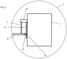
Figur 2 in der Schnittlinie A-A. - In
Figur 1 ist ein landwirtschaftliches Einachsfahrzeug dargestellt, welches in erster Linie aus einer Mittelachse 1 besteht, welche einends eine erste Stachelwalze 2 und andernends eine zweite Stachelwalze 3 aufweist. - Außerdem ist ein an der Mittelachse ein koppelbar verbundenes Landwirtschaftswerkzeug 4 gezeigt. Eine Vorschubrichtung 6 zeigt an, dass das landwirtschaftliche Einachsfahrzeug in Richtung des Landwirtschaftswerkzeugs 4 verfahren wird. Außerdem ist in der
Figur 1 schematisch an der Mittelachse 1 ein schwenkbar gehaltertes Trittbrett 5 gezeigt. Das Trittbrett 5 ist dabei auf der dem Landwirtschaftswerkzeug 4 abgewandten Seite der Mittelachse 1 angeordnet. - In
Figur 2 ist eine Ansicht von hinten also in Richtung der Vorschubrichtung 6 gezeigt. - Dort ist zu erkennen, dass das Trittbrett 5 eine Pendelstange 7 aufweist, wobei die Pendelstange 7 einends das Trittbrett 5 ausbildet und andernends ein Pendelgelenk 10.
- Die ersten Pendelpfeile 11 deuten an, dass das Trittbrett 5 in Richtung der ersten Stachelwalze 2 hin pendeln kann. Die zweiten Pendelpfeile 12 deuten an, dass das Trittbrett 5 in einer anderen Lage zu der zweiten Stachelwalze 3 hin pendeln können.
- Dabei umfasst die Mittelachse 1 das Pendelgelenk 10.
- Das Trittbrett 5 bildet außerdem eine erste Seitenwand 8 und eine zweite Seitenwand 9 aus. Dadurch formt das Trittbrett 5 eine U-förmige Rinne mit ebenem Rinnenboden aus.
- Die Mittelachse 1 weist weiterhin eine Festlegekulisse 13 auf. Die Festlegekulisse 13 bildet dabei eine Teilkreisform, um die Pendelbewegung des Trittbretts 5 abzubilden.
- Zuletzt ist eine Schnittlinie A-A gezeigt. In der
Figur 3 ist die Schnittansicht derFigur 2 an der Schnittlinie A-A gezeigt. Dabei ist die Sichtrichtung von der zweiten Stachelwalze 3 zu der ersten Stachelwalze 2 hin. - Das Trittbrett 5 eine Festlegeanordnung 14. Bei der Festleganordnung 14 handelt es sich um einen Stift, welcher zu der Festlegekulisse 13 hin ausgebildet ist.
- Dabei greift in
Figur 3 die Festlegeanordnung 14 in eine Festlegeausnehmung 15 der Festlegekulisse 13 ein. -
1 Mittelachse 2 Erste Stachelwalze 3 Zweite Stachelwalze 4 Landwirtschaftswerkzeug 5 Trittbrett 6 Vorschubrichtung 7 Pendelstange 8 Erste Seitenwand 9 Zweite Seitenwand 10 Pendelgelenk 11 Erster Pendelpfeil 12 Zweiter Pendelpfeil 13 Festlegekulisse 14 Festlegeanordnung 15 Festlegeausnehmung
Claims (6)
- Landwirtschaftliches Einachsfahrzeug mit einer Mittelachse (1), wobei die Mittelachse (1) jeweils endseitig eine Stachelwalze (2, 3) aufweist, wobei die Mittelachse (1) einen Antrieb aufweist und ein koppelbar verbundenes Landwirtschaftswerkzeug (4),
wobei
die Mittelachse (1) ein schwenkbar gehaltertes Trittbrett (5) umfasst, dadurch gekennzeichnet, dass die Mittelachse (1) eine Festlegekulisse (13) aufweist, wobei das Trittbrett (5) eine Festlegeanordnung (14) umfasst und die Festlegeanordnung (14) in eine Festlegeausnehmung (15) der Festlegekulisse (13) einbringbar ist. - Landwirtschaftliches Einachsfahrzeug nach Anspruch 1, dadurch gekennzeichnet, dass das Trittbrett (5) eine Pendelstange (7) aufweist, wobei die Pendelstange (7) einends das Trittbrett (5) ausbildet und andernends ein Pendelgelenk (10).
- Landwirtschaftliches Einachsfahrzeug nach Anspruch 2, dadurch gekennzeichnet, dass die Mittelachse (1) das Pendelgelenk (10) umfasst.
- Landwirtschaftliches Einachsfahrzeug nach einem der vorigen Ansprüche, dadurch gekennzeichnet, dass das Trittbrett (5) eine erste Seitenwand (8) und eine zweite Seitenwand (9) aufweist.
- Landwirtschaftliches Einachsfahrzeug nach einem der vorigen Ansprüche, dadurch gekennzeichnet, dass an die Mittelachse (1) das Trittbrett (5) über eine Pendelstange (7) anbringbar ist, wobei die Pendelstange (7) einends das Trittbrett (5) ausbildet und andernends ein Pendelgelenk (10) ausbildet, wobei die Mittelachse (1) das Pendelgelenk (10) eine Festlegekulisse (13) aufweist und das Trittbrett (5) eine Festlegeanordnung (14) umfasst, wobei die Festlegeanordnung (14) in eine Festlegeausnehmung (15) der Festlegekulisse (13) einbringbar ist.
- Landwirtschaftliches Einachsfahrzeug nach Anspruch 5, gekennzeichnet durch eine erste Seitenwand (8) und eine zweite Seitenwand (9).
Applications Claiming Priority (2)
| Application Number | Priority Date | Filing Date | Title |
|---|---|---|---|
| DE102019105531.8A DE102019105531B4 (de) | 2019-03-05 | 2019-03-05 | Landwirtschaftliches Einachsfahrzeug mit schwenkbar gehaltertem Trittbrett |
| DE202019101237.4U DE202019101237U1 (de) | 2019-03-05 | 2019-03-05 | Landwirtschaftliches Einachsfahrzeug und Trittbrett zur Nachrüstung eines landwirtschaftlichen Einachsfahrzeugs |
Publications (3)
| Publication Number | Publication Date |
|---|---|
| EP3704920A1 EP3704920A1 (de) | 2020-09-09 |
| EP3704920B1 true EP3704920B1 (de) | 2024-07-10 |
| EP3704920C0 EP3704920C0 (de) | 2024-07-10 |
Family
ID=69844378
Family Applications (1)
| Application Number | Title | Priority Date | Filing Date |
|---|---|---|---|
| EP20160954.2A Active EP3704920B1 (de) | 2019-03-05 | 2020-03-04 | Landwirtschaftliches einachsfahrzeug |
Country Status (1)
| Country | Link |
|---|---|
| EP (1) | EP3704920B1 (de) |
Citations (1)
| Publication number | Priority date | Publication date | Assignee | Title |
|---|---|---|---|---|
| US20080196374A1 (en) * | 2006-12-19 | 2008-08-21 | Gamble Jesse R | Mower with cushioned suspension for operator support platform having stowed and deployed positions |
Family Cites Families (6)
| Publication number | Priority date | Publication date | Assignee | Title |
|---|---|---|---|---|
| DE102005026761A1 (de) | 2005-06-09 | 2006-12-21 | Martin Brielmaier | Fahrzeug |
| DE102005026754A1 (de) | 2005-06-09 | 2006-12-21 | Martin Brielmaier | Fahrzeug |
| AT513971B1 (de) * | 2013-08-07 | 2014-09-15 | Stöckl Friedrich | Einachsiges Fahrzeug |
| CN203934286U (zh) * | 2014-07-16 | 2014-11-12 | 杨毅坚 | 电瓶驱动变频电机的微耕机 |
| EP3251481B1 (de) * | 2016-05-30 | 2021-01-27 | Brielmaier Motormäher GmbH | Einachsgeräteträger und anbaugerät für einen einachsgeräteträger |
| DE102016110810A1 (de) * | 2016-06-13 | 2017-12-14 | Martin Brielmaier | Einachsgeräteträger und Anbaugerät für einen Einachsgeräteträger |
-
2020
- 2020-03-04 EP EP20160954.2A patent/EP3704920B1/de active Active
Patent Citations (1)
| Publication number | Priority date | Publication date | Assignee | Title |
|---|---|---|---|---|
| US20080196374A1 (en) * | 2006-12-19 | 2008-08-21 | Gamble Jesse R | Mower with cushioned suspension for operator support platform having stowed and deployed positions |
Also Published As
| Publication number | Publication date |
|---|---|
| EP3704920A1 (de) | 2020-09-09 |
| EP3704920C0 (de) | 2024-07-10 |
Similar Documents
| Publication | Publication Date | Title |
|---|---|---|
| DE19655123C2 (de) | Bearbeitungsgerät für die Tiefenlockerung von Böden | |
| EP0150742B1 (de) | Schutzeinrichtung in Form eines Schutzschildes zum Abdecken einer Zapfwelle | |
| DE60315855T2 (de) | Schälpflug und sicherheitsvorrichtung für einen entsprechenden schälpflug | |
| EP0062734B1 (de) | Pflug mit einer Schnitt- und Zugpunkteinstellung | |
| DE102015221720A1 (de) | Verfahren und Vorrichtung zum Betreiben eines Kraftfahrzeugs, Kraftfahrzeug | |
| DE2834529A1 (de) | Gelenkbeschlag fuer sitze mit verstellbarer rueckenlehne, insbesondere kraftfahrzeugsitze | |
| DE3331534C2 (de) | ||
| EP3704920B1 (de) | Landwirtschaftliches einachsfahrzeug | |
| EP3573850B1 (de) | Traktionshilfe für den reifen eines kraftfahrzeugs | |
| DE102014112919B4 (de) | Fahrzeugsitz mit einer Verstelleinrichtung zur Verstellung zweier Verstell-Elemente sowie Verfahren zum Herstellen des Fahrzeugsitzes | |
| DE102019105531B4 (de) | Landwirtschaftliches Einachsfahrzeug mit schwenkbar gehaltertem Trittbrett | |
| DE202019101237U1 (de) | Landwirtschaftliches Einachsfahrzeug und Trittbrett zur Nachrüstung eines landwirtschaftlichen Einachsfahrzeugs | |
| DE602006000600T2 (de) | Anhängerkupplung | |
| EP2070402B1 (de) | Bodenbelüftungsvorrichtung | |
| DE3504865C2 (de) | Pflug mit Schnittbreiteneinstellung | |
| EP1154681A1 (de) | Mähaufbereiter | |
| DE2806960A1 (de) | Landwirtschaftliche maschine | |
| DE102019131595B4 (de) | Fahrzeugsitz | |
| DE10318927B4 (de) | Kopfstütze in Form eines mehrteiligen Netzes | |
| DE102005016789A1 (de) | Anordnung einer Lenksäule | |
| EP0072877A1 (de) | Hydraulik-Lenkzylinder | |
| DE9414597U1 (de) | Gezogene Mähmaschine | |
| DE69925127T2 (de) | Geräteanschlussvorrichtung und -verfahren | |
| EP4520149A1 (de) | Walzenanordnung | |
| DD253935A1 (de) | Klappvorrichtung fuer die aussenrahmen von bodenbearbeitungsgeraeten |
Legal Events
| Date | Code | Title | Description |
|---|---|---|---|
| PUAI | Public reference made under article 153(3) epc to a published international application that has entered the european phase |
Free format text: ORIGINAL CODE: 0009012 |
|
| STAA | Information on the status of an ep patent application or granted ep patent |
Free format text: STATUS: THE APPLICATION HAS BEEN PUBLISHED |
|
| AK | Designated contracting states |
Kind code of ref document: A1 Designated state(s): AL AT BE BG CH CY CZ DE DK EE ES FI FR GB GR HR HU IE IS IT LI LT LU LV MC MK MT NL NO PL PT RO RS SE SI SK SM TR |
|
| AX | Request for extension of the european patent |
Extension state: BA ME |
|
| RAP1 | Party data changed (applicant data changed or rights of an application transferred) |
Owner name: BRIELMAIER MOTORMAEHER GMBH |
|
| RIN1 | Information on inventor provided before grant (corrected) |
Inventor name: MARTIN BRIELMEIER |
|
| STAA | Information on the status of an ep patent application or granted ep patent |
Free format text: STATUS: REQUEST FOR EXAMINATION WAS MADE |
|
| 17P | Request for examination filed |
Effective date: 20210304 |
|
| RBV | Designated contracting states (corrected) |
Designated state(s): AL AT BE BG CH CY CZ DE DK EE ES FI FR GB GR HR HU IE IS IT LI LT LU LV MC MK MT NL NO PL PT RO RS SE SI SK SM TR |
|
| RAP3 | Party data changed (applicant data changed or rights of an application transferred) |
Owner name: BRIELMAIER MOTORMAEHER GMBH |
|
| STAA | Information on the status of an ep patent application or granted ep patent |
Free format text: STATUS: EXAMINATION IS IN PROGRESS |
|
| 17Q | First examination report despatched |
Effective date: 20211112 |
|
| P01 | Opt-out of the competence of the unified patent court (upc) registered |
Effective date: 20230529 |
|
| GRAP | Despatch of communication of intention to grant a patent |
Free format text: ORIGINAL CODE: EPIDOSNIGR1 |
|
| STAA | Information on the status of an ep patent application or granted ep patent |
Free format text: STATUS: GRANT OF PATENT IS INTENDED |
|
| INTG | Intention to grant announced |
Effective date: 20240205 |
|
| RAP1 | Party data changed (applicant data changed or rights of an application transferred) |
Owner name: RAPID TECHNIC GMBH |
|
| GRAS | Grant fee paid |
Free format text: ORIGINAL CODE: EPIDOSNIGR3 |
|
| GRAA | (expected) grant |
Free format text: ORIGINAL CODE: 0009210 |
|
| STAA | Information on the status of an ep patent application or granted ep patent |
Free format text: STATUS: THE PATENT HAS BEEN GRANTED |
|
| AK | Designated contracting states |
Kind code of ref document: B1 Designated state(s): AL AT BE BG CH CY CZ DE DK EE ES FI FR GB GR HR HU IE IS IT LI LT LU LV MC MK MT NL NO PL PT RO RS SE SI SK SM TR |
|
| REG | Reference to a national code |
Ref country code: CH Ref legal event code: EP |
|
| REG | Reference to a national code |
Ref country code: DE Ref legal event code: R096 Ref document number: 502020008498 Country of ref document: DE |
|
| P04 | Withdrawal of opt-out of the competence of the unified patent court (upc) registered |
Free format text: CASE NUMBER: APP_45343/2024 Effective date: 20240805 |
|
| U01 | Request for unitary effect filed |
Effective date: 20240802 |
|
| U07 | Unitary effect registered |
Designated state(s): AT BE BG DE DK EE FI FR IT LT LU LV MT NL PT SE SI Effective date: 20240808 |
|
| P05 | Withdrawal of opt-out of the competence of the unified patent court (upc) changed |
Free format text: CASE NUMBER: APP_45343/2024 Effective date: 20240808 |
|
| PG25 | Lapsed in a contracting state [announced via postgrant information from national office to epo] |
Ref country code: NO Free format text: LAPSE BECAUSE OF FAILURE TO SUBMIT A TRANSLATION OF THE DESCRIPTION OR TO PAY THE FEE WITHIN THE PRESCRIBED TIME-LIMIT Effective date: 20241010 |
|
| PG25 | Lapsed in a contracting state [announced via postgrant information from national office to epo] |
Ref country code: GR Free format text: LAPSE BECAUSE OF FAILURE TO SUBMIT A TRANSLATION OF THE DESCRIPTION OR TO PAY THE FEE WITHIN THE PRESCRIBED TIME-LIMIT Effective date: 20241011 Ref country code: PL Free format text: LAPSE BECAUSE OF FAILURE TO SUBMIT A TRANSLATION OF THE DESCRIPTION OR TO PAY THE FEE WITHIN THE PRESCRIBED TIME-LIMIT Effective date: 20240710 |
|
| PG25 | Lapsed in a contracting state [announced via postgrant information from national office to epo] |
Ref country code: IS Free format text: LAPSE BECAUSE OF FAILURE TO SUBMIT A TRANSLATION OF THE DESCRIPTION OR TO PAY THE FEE WITHIN THE PRESCRIBED TIME-LIMIT Effective date: 20241110 |
|
| PG25 | Lapsed in a contracting state [announced via postgrant information from national office to epo] |
Ref country code: HR Free format text: LAPSE BECAUSE OF FAILURE TO SUBMIT A TRANSLATION OF THE DESCRIPTION OR TO PAY THE FEE WITHIN THE PRESCRIBED TIME-LIMIT Effective date: 20240710 |
|
| PG25 | Lapsed in a contracting state [announced via postgrant information from national office to epo] |
Ref country code: ES Free format text: LAPSE BECAUSE OF FAILURE TO SUBMIT A TRANSLATION OF THE DESCRIPTION OR TO PAY THE FEE WITHIN THE PRESCRIBED TIME-LIMIT Effective date: 20240710 Ref country code: RS Free format text: LAPSE BECAUSE OF FAILURE TO SUBMIT A TRANSLATION OF THE DESCRIPTION OR TO PAY THE FEE WITHIN THE PRESCRIBED TIME-LIMIT Effective date: 20241010 |
|
| PG25 | Lapsed in a contracting state [announced via postgrant information from national office to epo] |
Ref country code: RS Free format text: LAPSE BECAUSE OF FAILURE TO SUBMIT A TRANSLATION OF THE DESCRIPTION OR TO PAY THE FEE WITHIN THE PRESCRIBED TIME-LIMIT Effective date: 20241010 Ref country code: PL Free format text: LAPSE BECAUSE OF FAILURE TO SUBMIT A TRANSLATION OF THE DESCRIPTION OR TO PAY THE FEE WITHIN THE PRESCRIBED TIME-LIMIT Effective date: 20240710 Ref country code: NO Free format text: LAPSE BECAUSE OF FAILURE TO SUBMIT A TRANSLATION OF THE DESCRIPTION OR TO PAY THE FEE WITHIN THE PRESCRIBED TIME-LIMIT Effective date: 20241010 Ref country code: IS Free format text: LAPSE BECAUSE OF FAILURE TO SUBMIT A TRANSLATION OF THE DESCRIPTION OR TO PAY THE FEE WITHIN THE PRESCRIBED TIME-LIMIT Effective date: 20241110 Ref country code: HR Free format text: LAPSE BECAUSE OF FAILURE TO SUBMIT A TRANSLATION OF THE DESCRIPTION OR TO PAY THE FEE WITHIN THE PRESCRIBED TIME-LIMIT Effective date: 20240710 Ref country code: GR Free format text: LAPSE BECAUSE OF FAILURE TO SUBMIT A TRANSLATION OF THE DESCRIPTION OR TO PAY THE FEE WITHIN THE PRESCRIBED TIME-LIMIT Effective date: 20241011 Ref country code: ES Free format text: LAPSE BECAUSE OF FAILURE TO SUBMIT A TRANSLATION OF THE DESCRIPTION OR TO PAY THE FEE WITHIN THE PRESCRIBED TIME-LIMIT Effective date: 20240710 |
|
| PG25 | Lapsed in a contracting state [announced via postgrant information from national office to epo] |
Ref country code: SM Free format text: LAPSE BECAUSE OF FAILURE TO SUBMIT A TRANSLATION OF THE DESCRIPTION OR TO PAY THE FEE WITHIN THE PRESCRIBED TIME-LIMIT Effective date: 20240710 |
|
| PG25 | Lapsed in a contracting state [announced via postgrant information from national office to epo] |
Ref country code: CZ Free format text: LAPSE BECAUSE OF FAILURE TO SUBMIT A TRANSLATION OF THE DESCRIPTION OR TO PAY THE FEE WITHIN THE PRESCRIBED TIME-LIMIT Effective date: 20240710 |
|
| PG25 | Lapsed in a contracting state [announced via postgrant information from national office to epo] |
Ref country code: SK Free format text: LAPSE BECAUSE OF FAILURE TO SUBMIT A TRANSLATION OF THE DESCRIPTION OR TO PAY THE FEE WITHIN THE PRESCRIBED TIME-LIMIT Effective date: 20240710 |
|
| U20 | Renewal fee for the european patent with unitary effect paid |
Year of fee payment: 6 Effective date: 20250324 |
|
| PLBE | No opposition filed within time limit |
Free format text: ORIGINAL CODE: 0009261 |
|
| STAA | Information on the status of an ep patent application or granted ep patent |
Free format text: STATUS: NO OPPOSITION FILED WITHIN TIME LIMIT |
|
| 26N | No opposition filed |
Effective date: 20250411 |
|
| PGFP | Annual fee paid to national office [announced via postgrant information from national office to epo] |
Ref country code: CH Payment date: 20250401 Year of fee payment: 6 |
|
| PG25 | Lapsed in a contracting state [announced via postgrant information from national office to epo] |
Ref country code: MC Free format text: LAPSE BECAUSE OF FAILURE TO SUBMIT A TRANSLATION OF THE DESCRIPTION OR TO PAY THE FEE WITHIN THE PRESCRIBED TIME-LIMIT Effective date: 20240710 |
|
| GBPC | Gb: european patent ceased through non-payment of renewal fee |
Effective date: 20250304 |
|
| PG25 | Lapsed in a contracting state [announced via postgrant information from national office to epo] |
Ref country code: GB Free format text: LAPSE BECAUSE OF NON-PAYMENT OF DUE FEES Effective date: 20250304 |
|
| PG25 | Lapsed in a contracting state [announced via postgrant information from national office to epo] |
Ref country code: IE Free format text: LAPSE BECAUSE OF NON-PAYMENT OF DUE FEES Effective date: 20250304 |
|
| PG25 | Lapsed in a contracting state [announced via postgrant information from national office to epo] |
Ref country code: RO Free format text: LAPSE BECAUSE OF FAILURE TO SUBMIT A TRANSLATION OF THE DESCRIPTION OR TO PAY THE FEE WITHIN THE PRESCRIBED TIME-LIMIT Effective date: 20240710 |
|
| REG | Reference to a national code |
Ref country code: CH Ref legal event code: U11 Free format text: ST27 STATUS EVENT CODE: U-0-0-U10-U11 (AS PROVIDED BY THE NATIONAL OFFICE) Effective date: 20260423 |
|
| U20 | Renewal fee for the european patent with unitary effect paid |
Year of fee payment: 7 Effective date: 20260324 |