EP3704587B1 - Software-umgebung zur fehlerbeseitigung, prüfung, kalibrierung und abstimmung in steuergerät - Google Patents
Software-umgebung zur fehlerbeseitigung, prüfung, kalibrierung und abstimmung in steuergerät Download PDFInfo
- Publication number
- EP3704587B1 EP3704587B1 EP18795636.2A EP18795636A EP3704587B1 EP 3704587 B1 EP3704587 B1 EP 3704587B1 EP 18795636 A EP18795636 A EP 18795636A EP 3704587 B1 EP3704587 B1 EP 3704587B1
- Authority
- EP
- European Patent Office
- Prior art keywords
- code
- debug
- calibration
- codes
- hardware
- Prior art date
- Legal status (The legal status is an assumption and is not a legal conclusion. Google has not performed a legal analysis and makes no representation as to the accuracy of the status listed.)
- Active
Links
Images


Classifications
-
- G—PHYSICS
- G06—COMPUTING OR CALCULATING; COUNTING
- G06F—ELECTRIC DIGITAL DATA PROCESSING
- G06F11/00—Error detection; Error correction; Monitoring
- G06F11/36—Prevention of errors by analysis, debugging or testing of software
- G06F11/3698—Environments for analysis, debugging or testing of software
-
- G—PHYSICS
- G06—COMPUTING OR CALCULATING; COUNTING
- G06F—ELECTRIC DIGITAL DATA PROCESSING
- G06F30/00—Computer-aided design [CAD]
- G06F30/30—Circuit design
- G06F30/32—Circuit design at the digital level
- G06F30/33—Design verification, e.g. functional simulation or model checking
- G06F30/3308—Design verification, e.g. functional simulation or model checking using simulation
-
- G—PHYSICS
- G06—COMPUTING OR CALCULATING; COUNTING
- G06F—ELECTRIC DIGITAL DATA PROCESSING
- G06F30/00—Computer-aided design [CAD]
- G06F30/30—Circuit design
- G06F30/34—Circuit design for reconfigurable circuits, e.g. field programmable gate arrays [FPGA] or programmable logic devices [PLD]
- G06F30/343—Logical level
-
- G—PHYSICS
- G06—COMPUTING OR CALCULATING; COUNTING
- G06F—ELECTRIC DIGITAL DATA PROCESSING
- G06F30/00—Computer-aided design [CAD]
- G06F30/30—Circuit design
-
- G—PHYSICS
- G06—COMPUTING OR CALCULATING; COUNTING
- G06F—ELECTRIC DIGITAL DATA PROCESSING
- G06F30/00—Computer-aided design [CAD]
- G06F30/30—Circuit design
- G06F30/32—Circuit design at the digital level
- G06F30/33—Design verification, e.g. functional simulation or model checking
Definitions
- the invention relates to the field of electric engine digital control domain, in particular targeting (but not limited to) control of pure electric or hybrid vehicle electric motors.
- the invention relates to methods related to code handling in the context of debug and/or test and/or calibration or tuning for the above domain and a variety of uses enabled by said methods and/or related codes, particular target hardware systems, use and arrangements thereof and software environments, platforms supporting or using said methods.
- the development flow is highly automated. This means that from control algorithm model to operational code running on ECU, there is basically no manual coding involved.
- the calibration task implies that some extra computing functions are added to the initial control algorithm in order to inject calibration value to some pre-defined parameters of the algorithm, and extract the values of some keys variables.
- the calibration infrastructure is, by definition, intrusive with regard to the control algorithm.
- Intrusiveness can be considered from two angles:
- Method for automated generating code from initial code exist (such as US 6742175 and/or " Automatic flight code generation with integrated static and run-time error checking and code analysis, XP 007905828 ) but none of them target nor deal with the specifics of a heterogeneous hardware system, comprising at least one software programmable unit and at least one hardware programmable unit, requiring a step of automatically generating codes, at least one per available unit.
- the invention in a first aspect of the invention relates to a method for automated generating of a plurality codes, suited for execution on a heterogeneous hardware system, comprising at least one software programmable unit and at least one hardware programmable unit, said codes include calibration instructions, said method comprising: (i) loading of initial (high-level simulation) code, including one or more code descriptions, (ii) loading calibration instructions; (iii) automatically generating of said codes (40), at least one per available unit, based on said loaded initial code and said loaded calibration instructions.
- the invention in a second aspect of the invention relates to an arrangement (part of or suitable to be part of a driving vehicle) comprising an electric engine; and an engine control unit hardware, providing (real-time) control for said engine, said engine control unit hardware comprising a heterogeneous hardware system comprising at least one software programmable unit and at least one hardware programmable unit and are executing the codes are generated by the methods of the first aspect of the invention.
- the invention relates to the related computer program product comprising computer-readable code, that when run on a computer system causes the computer system to execute the methods of any of the previous method claims.
- the invention relates to the related non-transitory machine-readable storage medium storing the computer program products described above.
- the invention relates to (i) methods related to code handling such as (multi-)code design, (semi-) automatically (multi-)code generation and (multi-)code execution, including debug and/or test and/or calibration or tuning and a variety of uses enabled by said methods and/or designed code, generated code and (ii) made suitable (via adaptations such as specific resources) target hardware systems, in particular heterogeneous hardware systems (and hence requiring multi-code), suitable target (application) systems, including those hardware systems, to support and/or optimally benefit from said methods.
- code handling such as (multi-)code design, (semi-) automatically (multi-)code generation and (multi-)code execution, including debug and/or test and/or calibration or tuning and a variety of uses enabled by said methods and/or designed code, generated code and (ii) made suitable (via adaptations such as specific resources) target hardware systems, in particular heterogeneous hardware systems (and hence requiring multi-code), suitable target (application) systems, including those hardware systems, to support and
- the invention in particular relates to the above wherein for one or more parts of said target (application) systems code descriptions are available and said (multi-) code design methods initially start from said one or more code descriptions, moreover said (multi-)code design method is adapted that its input must be suitable for the subsequent (semi-) automatically (multi-)code generation, which in itself is adapted for generating the variety of codes (denoted above multi-code) for the target hardware system.
- debug and/or test and/or calibration or tuning capabilities provided by the invented design and/or generation and/or execution and/or simulation environment (or framework) provided by the invention are adapted to sufficiently protect the original (multi-)code), being code before any instructions, code or the like, related to debug and/or test and/or calibration or tuning is added.
- the invented particularly designed methods enable deployment of a variety of (semi-) automatable uses such as tuning or calibration and/or compare with references (high level abstractions). Moreover those methods also ensure that the hardware systems their hardware limitations can be taken into account (say at their limit as the designer is invited to explore how much extra code can be afforded) while designing for optimal performance in combination with safe execution (by avoiding manual code manipulation and/or providing more than sufficient test/debug and calibration opportunities) for and required by the target (application) system.
- the invention hence provides designs methods for designing code, starting from and loading of initial code, including one or more system code descriptions, loading debug, test or calibration instructions, further (semi-)automatically generation of further code, suitable for programming of or execution on the target hardware systems, more in particular a heterogeneous hardware system, hence a plurality of further codes are generated, said generating methods, starting from and loading said designed code and loading instructions on which debug, test or calibration instructions to be used. Said generating methods can be integrated directly in said design methods. While said hardware system and/or application system may be connected to debug, test or calibration equipment to provide the related function, the generating methods and/or integrated design method may also include generating of code suitable for steering such equipment.
- the invention in particular relates to the above wherein for one or more parts of said target (application) systems code descriptions are available, also called a model, and hence said methods can be called model-based.
- a typical target application are electric engines as found in pure electric or hybrid vehicle electrical motors and hence the (digital) control thereof.
- the initial code is a high-level (simulation) code, such as but not limited to Matlab or Simulink code or the like).
- the calibrations require data transfer related thereto, data transfer which is typically more demanding than during ordinary use of the calibrated system.
- target heterogeneous hardware systems specific resources such as internal memory such as on-chip RAM, interconnect permitting data transfer to the core or programmable matrix and input/output ports towards said memory
- specific resources such as internal memory such as on-chip RAM, interconnect permitting data transfer to the core or programmable matrix and input/output ports towards said memory
- the invention provides designs methods for designing/generating code, starting from and loading of initial code, including one or more system code descriptions, in particular comprising a system model and/or a control model thereof and loading debug, test or calibration instructions (for injection of parameters and/or extraction of variables).
- the invention provides methods for designing/generating code to have calibration features included in operational mode with preferably absolutely no modification of golden model and preferably no manual overrides of generated code.
- control algorithm is split between software execution on microprocessor core(s) and hardware execution on FLU.
- the operational code is auto-generated from model.
- the invention further improves designs methods for designing code, starting from and loading of initial code, including one or more system code descriptions, (semi-)automatically generation of further code, suitable for programming of or execution on a heterogeneous hardware system, hence a plurality of further codes are generated, whereby the mapping of said code descriptions on the various parts of the hardware system is defined by the designer in a particular way.
- the invention provides now design methods, enabling addition of calibration (and the like) instructions, whereby the mapping of the related code thereto on the various parts of the hardware system is defined by the designer in the same way as in the original design method.
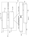
- the invention method provides a method for automated generating of a plurality codes (40) comprising: (i) loading of initial (high-level simulation) code (10), including one or more code descriptions (golden model), (ii) loading calibration instructions (20) (meta data); (iii) automatically generation (30) of said codes, at least one per available unit (hence (50) for software for the software programmable unit being a microprocessor core and (60) being hardware description language code for said hardware programmable unit being a programmable logic matrix), based on said loaded initial code and said loaded calibration instructions.
- the generated codes rely on the FPCU debug or CAN communication ports to transmit/receive calibration data from/to external calibration devices.
- the (semi-)automatically generation of (further) codes (50, 60) provides, besides the code it would originally generate (70) (80), extra code related to said calibration, in particular extra operational calibration code for said cores (90) (e.g. C code) and calibration hardware description language code (100) for said programmable matrixes is generated, more especially said codes (90)(100) permit to override and/or to sample the value of a variable (as indicated in the calibration or a like instructions) in the respective original codes (70)(80).
- extra code related to said calibration in particular extra operational calibration code for said cores (90) (e.g. C code) and calibration hardware description language code (100) for said programmable matrixes is generated, more especially said codes (90)(100) permit to override and/or to sample the value of a variable (as indicated in the calibration or a like instructions) in the respective original codes (70)(80).
- the loading of those high-level calibration instructions is not necessary a one bulk loading of code, but may include a step of changing (in a particular way) the initial loaded simulation code.
- the automatically generation of codes hence, received as input then a modified simulation code.
- the step of automatically generating which is performed by a combination of a software compiler and a programmable unit mapping tool, has to be adapted to recognized those calibration instructions and act accordingly.
- the invention can hence formally be defined as a method for automated generating of a plurality codes, suited for execution on a heterogeneous hardware system (200), comprising at least one software programmable unit (210) and at least one hardware programmable unit (220), said codes include executable calibration instructions, said method comprising: (i) loading of initial (high-level simulation) code (10), including one or more code descriptions, (ii) providing or loading high-level calibration instructions (20); (iii) automatically generation (30) of said codes (40), at least one per available unit, based on (i) said loaded initial code and said provided or loaded calibration instructions or (ii) said initial code as modified by said provided calibration instructions, whereby said automatically generation step is adapted for generating extra (execution) code related to said calibration based on said provided or loaded (high-level) calibration instructions.
- the invention provides for a design and/or calibration (debug, test) framework, more in particular a software environment, compiled for operating on one or more computers, for supporting or facilitating the methods described above and hence also relates to computer program products A (and related non-transitory machine-readable storage media) comprising computer-readable code, that when run on a computer system causes the computer system to execute those
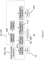
- the invention hence provides a software environment (300) for automated generating of a plurality codes, suited for execution on a heterogeneous hardware system (200), comprising at least one software programmable unit (210) and at least one hardware programmable unit (220), said codes include calibration instructions, said method comprising: (i) loading initial codes (320), modified by or with calibration instructions (by use of annotations or meta data) and (ii) automatically generation (30) of said codes (40), at least one per available unit, based on the loaded codes.
- the invention further provides a software environment (310) for automated generating of a plurality codes, suited for execution on a heterogeneous hardware system (200), comprising at least one software programmable unit (210) and at least one hardware programmable unit (220), said codes include calibration instructions, said method comprising: (i) loading of initial (high-level simulation) code (10), including one or more code descriptions, (ii) loading calibration instructions (20); (iii) automatically generation (310) of said codes (40), at least one per available unit, based on said loaded initial code and said loaded calibration instructions, be it with an intermediate steps of modifying and/or annotating and automatically generation thereafter.
- calibration equipment (330) is also provided and the methods and related software environment also automatically generating of code (340), suited for steering calibration equipment to be connected to said heterogeneous hardware system.
- the invention therefore provides a variety of arrangements, in particular a first arrangement with a computer systems configured with the design or calibration framework, a second arrangement including said first arrangement and the heterogeneous hardware system, for which it generates code, a third arrangement including said first and/or second arrangement, further including said calibration equipment and a fourth arrangement, comprising the so to speak device under test (e.g.
- an electric engine and an engine control unit hardware, providing (real-time) control for said engine of which the heterogeneous hardware system is part), the portions of these arrangement performing their functions as discussed before but firmly interconnected via the codes they share and the data streams (instructions, outcomes) they generate and in particular the fact that the particularities of the portions (heterogeneous, real-time constraints) are taken in account where needed while hiding that for the user via the automatic approach.
- the hardware (200) has limitations on the amount of code it can execute and as during calibration extra (automatically generated) code needs to be loaded on and executed by it, the user or designer might be inclined or forced to take this into account, which might even lead to a bad outcome.
- a user or designer or tester should be able to design his or her debug, test or calibration approach, without having to worry (too much) about this problem or at least have a possibility to separate this concern from his approach development.
- the invention enables this as by providing the calibration instructions (e.g.
- the user may in a preferred embodiment also provide instructions (350), indicating which ones to use at a certain stage (and hence a subset is generated fitting within the hardware).
- the user or designer can now execute this strategy in a step by step manner without any code rewriting effort.
- the software environment even indicates the degree of fit, and hence guides the user or designer in creating his step by step use of this strategy.
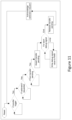
- FIG. 4 Yet another functionality enabled by the invention as illustrated in Figure 4 (and a further exemplary embodiment there is shown in Figure 5 ) is that it support now the possibility to perform an auto calibration feedback loop, starting from receiving data from the calibration equipment and/or from other measurements on the device under test and changing the calibration parameters fed to the hardware system.
- the software environment has means (400) for receiving data, preparing parameters in accordance with the received data and further in accordance with user instructions (410) on how he or she prefer the auto calibration loop to be executed (e.g. parameter range and the discretisation step).
- the user does not have to coordinate anymore the operations of the hardware, the calibration equipment nor adapt codes nor parameters in it. This is all automatically supported by the environment.
- the above described functionalities of the invention is to emphasize that calibration infrastructure is able to extract some curves of the evolution of internal algorithm variables over time.
- the raw data is stores in FPCU on-chip RAM and can be read-out by state of the art equipment through either debug or CAN port. Once this raw data is read out, the problem is to be able to isolate the block of data corresponding to each and any of the variables monitored by calibration infrastructure. Thanks to the "meta-data" based flow and associated auto-generation program, it is possible to auto-generate the configuration scripts that would allow the debug equipment to extract the data curve and compare them to their ideal values in the golden model.
- Figure 6 provides the overview of the processing flow from user input (the user annotated model 320 by step (350)) to generated material (50), (60), (80), (100), (340). Each part of the flow is detailed below.
- model meta data assignment part of the flow relies on specific Matlab GUI extensions. Those extensions can be executed from (a Matlab) user interface based on contextual menu available on connection signals between processing operators boxes of the simulation model developed by the final user. An exemplary embodiment is shown in Figure 7 .
- the signals list gathering step is a full automatic program. This process prepares a list of calibration and debug signals for the following parts of the flow.
- the C code generator is a full automatic program. This process automatically generates the embedded software C code that should be compiled and linked with user defined application software to include debug and trace capabilities.
- the generated code is a simple header file providing the signals memory mapping information.
- the HDL code generator is a full automatic program, generating a HDL module able to properly execute calibration/debug data transfer from/to on-chip memory. This generated module shall be further connected to the "golden” HDL generated from Matlab model. This connection is done in next phase of the processing flow (HDL integration generator).
- This module is generated with input/output ports as shown in Figure 8 .
- the main challenges solved by the generated module are:
- Figure 9 shows a typical behavior of real time control loop algorithm mapped in embedded FPGA. It is basically made of three phases:
- the challenge solve is to have a mechanism that restrict the debug and calibration data transfer to acquisition and update periods.
- the debug data transfer process in generated HDL module as shown in Figure 10 is dedicated to transferring the value of previously identified debug signals to on-chip RAM.
- the calibration data transfer process in generated HDL module as shown in Figure 11 is dedicated to transferring the value of previously identified calibration signals to on-chip RAM.
- the HDL integration generator is a full automatic program.
- the debugger script generator is an automatic program that takes as input the list of debug signal and associated memory mapping computed from first phases of the flow.
- the code generating steps comprises of a plurality of sub steps, starting with an automated signals list gathering step from its input code (model data-base), resulting in a list of calibration and debug signals, suitable for the following parts of the flow.
- Another step is automatic C code generator, providing the software C code that should be compiled and linked with user defined application software to include debug and trace capabilities. The generated code provides the signals memory mapping information.
- Yet another step is the automatic HDL code generator, generating a HDL module able to properly execute calibration/debug data transfer from/to on-chip memory.
- This generated module shall be further connected to the "golden" HDL generated from the model, by the next sub step being the HDL integration generator, providing a HDL module for performing data transfer from and to (on-chip) memory (RAM) in sync with golden model iteration to avoid conflict by supporting a mechanism that restrict the debug and calibration data transfer to identified acquisition and update periods.
- the HDL integration generator sub step automatically generating an HDL wrapper that instantiate both Golden HDL model and Previously generated RAM logger module and then create wire connections between both.
- the automatic debugger script generator sub step takes as input the list of debug signal and associated memory mapping computed from first phases of the flow and based on this information it generates a set of scripts in the language of the target debugger system.
- debug infrastructure 700
- debug and trace infrastructure can be available and is responsible from: (1) Gathering all the debug and trace data all over the circuit thanks to various intrusive elements :
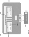
- the invention hence provides a method for automated generating of a plurality codes, suited for execution on a heterogeneous hardware system (200), comprising at least one software programmable unit (210) and at least one hardware programmable unit (220) and debug and test infrastructure (700), said codes include executable debug and/or test instructions, said method comprising: (i) loading of initial code (10), including one or more code descriptions, (ii) providing user debug and/or test instructions (20), specifying those variables in the code descriptions to be considered as calibration parameters and/or those variables in the code descriptions to be considered as to be monitored values, on said initial code (10); (iii) a step of automatically generating (30) of said codes (40), at least one per available unit, based on said loaded initial code, provided with debug and/or test instructions, characterized in that an intermediate step (800) is foreseen, in particular a step (iii) of automatically generating (30) of said codes (40), at least one per available unit, based on said loaded initial code, provided
- the role of the code generation configurator (800) is to decide which of the three components is the most appropriate to manage a variable for debug & test.
- This software is able to analyse the golden model to understand which of the three elements has visibility on a given variable. Based on this, the software will allocate the variable management to the appropriate code generator.
Landscapes
- Engineering & Computer Science (AREA)
- Computer Hardware Design (AREA)
- Theoretical Computer Science (AREA)
- Physics & Mathematics (AREA)
- General Engineering & Computer Science (AREA)
- General Physics & Mathematics (AREA)
- Quality & Reliability (AREA)
- Evolutionary Computation (AREA)
- Geometry (AREA)
- Debugging And Monitoring (AREA)
Claims (10)
- Verfahren für ein automatisiertes Erzeugen einer Vielzahl von Codes, die geeignet sind für eine Ausführung in einem heterogenen Hardwaresystem (200), das mindestens eine Software-programmierbare Einheit (210) und mindestens eine Hardware-programmierbare Einheit (220) und spezifische Ressourcen (230) zum Unterstützen von Datenübertragungen in Bezug auf eine Fehlerbeseitigung und/oder eine Prüfung umfasst, wobei die Codes ausführbare Anweisungen (20) für eine Fehlerbeseitigung und/oder eine Prüfung enthalten, wobei das Verfahren umfasst:i) Laden eines anfänglichen Codes (10), der eine oder mehrere Codebeschreibungen enthält,ii) Bereitstellen von Benutzeranweisungen (20) für eine Fehlerbeseitigung und/oder eine Prüfung, die jene Variablen in den Codebeschreibungen, die als Kalibrierungsparameter betrachtet werden, und jene Variablen in den Codebeschreibungen festlegen, die als zu überwachende Werte betrachtet werden, in dem anfänglichen Code (10), und Hinzufügen jener Anweisungen zu dem anfänglichen Code;iii) einen Schritt eines automatischen Erzeugens (30), durch eine Kombination von einem Software-Compiler und einem Zuordnungswerkzeug einer programmierbaren Einheit, wobei die Vielzahl von Codes (40), mindestens einer pro zur Verfügung stehender Einheit, basierend auf dem geladenen anfänglichen Code, der mit Anweisungen für eine Fehlerbeseitigung und/oder eine Prüfung bereitgestellt wird, geeignet ist für eine Ausführung in dem heterogenen Hardwaresystem (200),wobei die Software-programmierbare Einheit (210) ein Mikroprozessor ist und sein entsprechender Code ein Software-Sprachcode (50) ist, undwobei die Hardware-programmierbare Einheit (220) eine programmierbare Logikmatrix ist und ihr entsprechender Code ein Code einer Hardwarebeschreibungssprache, HDL-Code, ist (60);wobei der Schritt iii) die folgenden Schritte aufweist- automatisiertes Sammeln einer Liste von Signalen aus dem geladenen anfänglichen Code, der mit Benutzeranweisungen für eine Fehlerbeseitigung und/oder eine Prüfung bereitgestellt wird, was zu einer Liste von Variablen oder Signalen führt, die den Kalibrierungsparametern oder den überwachten Werten entsprechen,- automatisiertes Erzeugen eines Softwarecodes, der kompiliert und mit einer benutzerdefinierten Anwendungssoftware verbunden wird, um Fehlerbeseitigungs- und Verfolgungsfähigkeiten zu enthalten, die den Signalen Speicherzuordnungsinformationen bereitstellen;- automatisiertes Erzeugen eines HDL-Modulcodes (100), der in der Lage ist, eine Kalibrierungsdatenübertragung von/zu einem chipinternen Speicher (240) auszuführen, der Teil der spezifischen Ressourcen (230) ist, wobei das automatisierte Erzeugen, neben den jeweiligen Standardcodes (70) (80), die es aus dem geladenen anfänglichen Code ohne die Kalibrierung und/oder die Anweisungen für eine Fehlerbeseitigung und/oder eine Prüfung erzeugen würde, Extracodes (90) (100) bereitstellt, die ein Außer-Acht-Lassen und/oder ein Abtasten eines Werts einer Variablen in den jeweiligen Originalcodes (70) (80) erlauben.
- Verfahren nach Anspruch 1, wobei iii) ein Schritt eines automatischen Erzeugens (30) der Codes (40), mindestens eines pro zur Verfügung stehender Einheit, basierend auf dem geladenen anfänglichen Code, der durch die Anweisungen für eine Fehlerbeseitigung und/oder eine Prüfung bereitgestellt wird, einen Schritt (a) eines automatisierten Ermittelns (800) umfasst, ob die für die Software-programmierbare Einheit (210) bzw. die Hardware-programmierbare Einheit (220) zu erzeugenden Codes mit den Anweisungen für eine Fehlerbeseitigung und/oder eine Prüfung bereitgestellt werden, oder die bereitgestellte Fehlerbeseitigungs- und Prüfungsinfrastruktur (700), wenn sie bereitgestellt wird, jene (oder einen Teil davon) und danach einen Schritt (b) eines automatischen Erzeugens (810) der Codes (40), mindestens eines pro zur Verfügung stehender Einheit, basierend auf dem geladenen anfänglichen Code, der mit den Anweisungen für eine Fehlerbeseitigung und/oder eine Prüfung bereitgestellt wird, basierend auf dem automatischen Ermitteln des Schritts (a) durchführt.
- Verfahren nach Anspruch 2, wobei der Schritt (a) (800) auf einem Ermitteln beruht, ob durch die Fehlerbeseitigungs- und Prüfungsinfrastruktur (700) und/oder das Laden des Codes in die Software-programmierbare Einheit (210) auf die Parameter oder Variablen zugegriffen wird.
- Verfahren nach einem der Ansprüche 1 bis 3, wobei das heterogene Hardwaresystem spezifische Ressourcen (230) enthält, um Datenübertragungen zu unterstützen, die sich auf eine Fehlerbeseitigung und/oder eine Prüfung beziehen und wobei die automatisch erzeugten Codes (40) jene Ressourcen ausnutzen.
- Verfahren nach Anspruch 1, wobei der Schritt iii) (a) den Schritt (630) eines Erzeugens einer HDL aus dem anfänglichen Code und (b) einen Schritt (620) eines Verbindens dieser erzeugten HDL mit dem erzeugten HDL-Modul enthält, wobei dieser Schritt (620) vorzugsweise die Liste von Kalibrierungssignalen verwendet.
- Verfahren nach einem der Ansprüche 1 bis 5, das ferner umfasst:- Ausführen - Simulieren - des anfänglichen Codes, der eine oder mehrere Codebeschreibungen enthält,- Ausführen des Codes, wie er aus dem anfänglichen Code erzeugt wurde, und- und iii) Vergleichen der Auswirkungen der Ausführungen, um die funktionelle Ähnlichkeit der Codes zu verifizieren.
- Anordnung, die einen Elektromotor; und eine Hardware einer Motorsteuereinheit umfasst, die eine Steuerung für den Motor bereitstellt, wobei die Hardware der Motorsteuereinheit ein heterogenes Hardwaresystem umfasst, das mindestens eine Software-programmierbare Einheit und mindestens eine Hardware-programmierbare Einheit umfasst, und wobei die Einheiten geeignet sind zum Ausführen der Codes, die durch die Verfahren nach einem der Ansprüche 1 bis 5 erzeugt werden.
- Kalibrierungsanordnung, welche die Anordnung nach Anspruch 7 und eine Kalibrierungsausrüstung umfasst, die an das heterogene Hardwaresystem und den Motor angeschlossen wird, wobei die Kalibrierungsausrüstung geeignet ist zum Ausführen des Codes, wie er durch das Verfahren nach Anspruch 1 erzeugt wird.
- Computerprogrammprodukt, das einen computerlesbaren Code umfasst, der, wenn er in einem Computersystem nach Anspruch 7 abläuft, das Computersystem veranlasst, die Verfahren nach einem der vorhergehenden Verfahrensansprüche auszuführen.
- Nicht-flüchtiges maschinenlesbares Speichermedium, in dem die Computerprogrammprodukte des vorhergehenden Anspruchs gespeichert sind.
Applications Claiming Priority (3)
| Application Number | Priority Date | Filing Date | Title |
|---|---|---|---|
| US201762580830P | 2017-11-02 | 2017-11-02 | |
| EP17199622 | 2017-11-02 | ||
| PCT/EP2018/079835 WO2019086519A1 (en) | 2017-11-02 | 2018-10-31 | Software environment for control engine debug, test, calibration and tuning |
Publications (2)
| Publication Number | Publication Date |
|---|---|
| EP3704587A1 EP3704587A1 (de) | 2020-09-09 |
| EP3704587B1 true EP3704587B1 (de) | 2025-03-19 |
Family
ID=64049267
Family Applications (1)
| Application Number | Title | Priority Date | Filing Date |
|---|---|---|---|
| EP18795636.2A Active EP3704587B1 (de) | 2017-11-02 | 2018-10-31 | Software-umgebung zur fehlerbeseitigung, prüfung, kalibrierung und abstimmung in steuergerät |
Country Status (5)
| Country | Link |
|---|---|
| US (2) | US11397663B2 (de) |
| EP (1) | EP3704587B1 (de) |
| JP (1) | JP7262818B2 (de) |
| CN (1) | CN111480150B (de) |
| WO (1) | WO2019086519A1 (de) |
Families Citing this family (9)
| Publication number | Priority date | Publication date | Assignee | Title |
|---|---|---|---|---|
| EP3704587B1 (de) * | 2017-11-02 | 2025-03-19 | Silicon Mobility SAS | Software-umgebung zur fehlerbeseitigung, prüfung, kalibrierung und abstimmung in steuergerät |
| US20230044219A1 (en) * | 2019-10-29 | 2023-02-09 | Silicon Mobility Sas | A secure hardware programmable architecture |
| CN112799649B (zh) * | 2020-06-15 | 2023-09-12 | 中兴通讯股份有限公司 | 代码构建方法、装置、设备和存储介质 |
| CN112433826B (zh) * | 2021-01-27 | 2021-04-20 | 南京芯驰半导体科技有限公司 | 混合异构虚拟化通信方法及芯片 |
| US11755459B2 (en) * | 2021-03-23 | 2023-09-12 | Western Digital Technologies, Inc. | Management of a debug buffer based on priority information |
| US11886837B2 (en) * | 2021-04-10 | 2024-01-30 | Accenture Global Solutions Limited | Simulation-based software design and delivery attribute tradeoff identification and resolution |
| US12355506B2 (en) * | 2021-10-22 | 2025-07-08 | Hughes Network Systems, Llc | Techniques for calibration and measurements of an E-band satellite communication (SATCOM) system |
| CN116955894B (zh) * | 2023-09-20 | 2024-01-09 | 肇庆星诺奇传动科技有限公司 | 一种在线自适应螺纹长度信息校准方法及系统 |
| US12505007B2 (en) | 2024-05-10 | 2025-12-23 | International Business Machines Corporation | Updating computing error analysis windows |
Family Cites Families (41)
| Publication number | Priority date | Publication date | Assignee | Title |
|---|---|---|---|---|
| US6742175B1 (en) * | 1998-10-13 | 2004-05-25 | Codagen Technologies Corp. | Component-based source code generator |
| US6581191B1 (en) * | 1999-11-30 | 2003-06-17 | Synplicity, Inc. | Hardware debugging in a hardware description language |
| US6823497B2 (en) * | 1999-11-30 | 2004-11-23 | Synplicity, Inc. | Method and user interface for debugging an electronic system |
| US7240303B1 (en) * | 1999-11-30 | 2007-07-03 | Synplicity, Inc. | Hardware/software co-debugging in a hardware description language |
| US20020072893A1 (en) * | 2000-10-12 | 2002-06-13 | Alex Wilson | System, method and article of manufacture for using a microprocessor emulation in a hardware application with non time-critical functions |
| US7222315B2 (en) * | 2000-11-28 | 2007-05-22 | Synplicity, Inc. | Hardware-based HDL code coverage and design analysis |
| JP2002230061A (ja) * | 2001-01-30 | 2002-08-16 | Matsushita Electric Ind Co Ltd | 半導体回路接続データベース及びこれを用いた半導体回路設計方法 |
| JP2002366602A (ja) * | 2001-04-06 | 2002-12-20 | Seiko Epson Corp | ソフトウエア及びハードウエアのシミュレーション方法及びシステム並びにプログラム |
| US20030056197A1 (en) * | 2001-08-30 | 2003-03-20 | Dennis Peter D. J. | Method and apparatus to facilitate debugging computer code within an operating system kernel |
| US6961924B2 (en) * | 2002-05-21 | 2005-11-01 | International Business Machines Corporation | Displaying variable usage while debugging |
| US7086017B1 (en) * | 2002-06-10 | 2006-08-01 | Xilinx, Inc. | Method of post-implementation simulation of a HDL design |
| US6996735B2 (en) * | 2002-11-22 | 2006-02-07 | Texas Instruments Incorporated | Apparatus for alignment of data collected from multiple pipe stages with heterogeneous retention policies in an unprotected pipeline |
| US7409652B1 (en) | 2004-06-04 | 2008-08-05 | Altera Corporation | Debuggable opaque IP |
| US20060005205A1 (en) * | 2004-06-08 | 2006-01-05 | Daniel Illowsky | Device interoperability framework and method for building interoperability applications for interoperable team of devices |
| US8087002B2 (en) * | 2006-04-04 | 2011-12-27 | Tibco Software Inc. | Method and system for providing a visual debugger for an interpreted statistical language |
| US9354944B2 (en) * | 2009-07-27 | 2016-05-31 | Advanced Micro Devices, Inc. | Mapping processing logic having data-parallel threads across processors |
| US20110258421A1 (en) * | 2010-04-19 | 2011-10-20 | International Business Machines Corporation | Architecture Support for Debugging Multithreaded Code |
| US9141831B2 (en) * | 2010-07-08 | 2015-09-22 | Texas Instruments Incorporated | Scheduler, security context cache, packet processor, and authentication, encryption modules |
| CN101923466B (zh) * | 2010-07-23 | 2014-04-16 | 清华大学 | 装饰器模式的指令的存取方法 |
| JP5672165B2 (ja) | 2011-06-16 | 2015-02-18 | 富士通株式会社 | テストデータ生成プログラム、テストデータ生成方法、テストデータ生成装置 |
| US8776025B2 (en) * | 2011-11-04 | 2014-07-08 | International Business Machines Corporation | Integrated debugger and code coverage tool |
| US20130125093A1 (en) * | 2011-11-11 | 2013-05-16 | General Electric Company | Generating object-oriented programming language code from a multi-domain dynamic simulation model |
| CN102902620B (zh) * | 2011-12-23 | 2015-06-03 | 同济大学 | 基于gdb的异构计算调试环境的实现系统 |
| JP5799823B2 (ja) | 2012-01-17 | 2015-10-28 | 富士通株式会社 | テストデータ生成装置、テストデータ生成プログラムおよびテストデータ生成方法 |
| US9135131B2 (en) * | 2012-02-16 | 2015-09-15 | National Instruments Corporation | Customizing operation of a test instrument based on information from a system under test |
| US9354998B2 (en) * | 2012-05-04 | 2016-05-31 | Aegis.Net, Inc. | Automated conformance and interoperability test lab |
| RU2012127578A (ru) * | 2012-07-02 | 2014-01-10 | ЭлЭсАй Корпорейшн | Анализатор применимости программного модуля для разработки и тестирования программного обеспечения для многопроцессорных сред |
| DE102012211981A1 (de) * | 2012-07-10 | 2014-01-16 | Dspace Digital Signal Processing And Control Engineering Gmbh | Verfahren und Vorrichtung zum Erstellen und Testen eines Steuergeräteprogramms |
| EP2917837B1 (de) * | 2012-11-09 | 2019-01-02 | Coherent Logix Incorporated | Echtzeitanalyse und steuerung für ein multiprozessorsystem |
| CN103049270A (zh) * | 2012-12-27 | 2013-04-17 | 福州福大自动化科技有限公司 | 人机界面软件的无脚本组态和调试方法 |
| US9053230B2 (en) * | 2013-01-14 | 2015-06-09 | International Business Machines Corporation | Framework and repository for analysis of software products |
| US9235395B2 (en) * | 2013-05-30 | 2016-01-12 | National Instruments Corporation | Graphical development and deployment of parallel floating-point math functionality on a system with heterogeneous hardware components |
| US9600398B2 (en) * | 2013-10-29 | 2017-03-21 | Synopsys, Inc. | Method and apparatus for debugging HDL design code and test program code |
| EP2940586B1 (de) | 2014-04-29 | 2023-03-01 | Hitachi, Ltd. | Verfahren und System zum Testen von Steuerungssoftware eines gesteuerten Systems |
| US9477807B1 (en) * | 2015-06-11 | 2016-10-25 | International Business Machines Corporation | Automating system on a chip customized design integration, specification, and verification through a single, integrated service |
| CN105550430B (zh) * | 2015-12-09 | 2019-01-01 | 中国船舶重工集团公司第七二六研究所 | 基于模型设计的通用型红外焦平面设备开发系统 |
| DE102017103732A1 (de) * | 2016-02-25 | 2017-08-31 | Infineon Technologies Austria Ag | Hardwareüberwachungsvorrichtung, Laufzeitüberwachungsvorrichtung und entsprechende Verfahren |
| CN115629829A (zh) * | 2016-03-23 | 2023-01-20 | 江森自控泰科知识产权控股有限责任公司 | 用于实时数据流编程的高效状态机 |
| US11042471B2 (en) * | 2017-08-25 | 2021-06-22 | Oracle International Corporation | System and method for providing a test manager for use with a mainframe rehosting platform |
| EP3704587B1 (de) * | 2017-11-02 | 2025-03-19 | Silicon Mobility SAS | Software-umgebung zur fehlerbeseitigung, prüfung, kalibrierung und abstimmung in steuergerät |
| US20190146758A1 (en) * | 2017-11-14 | 2019-05-16 | Microsoft Technology Licensing, Llc | Collaborative editing of source code with intelligent operations |
-
2018
- 2018-10-31 EP EP18795636.2A patent/EP3704587B1/de active Active
- 2018-10-31 US US16/760,196 patent/US11397663B2/en active Active
- 2018-10-31 WO PCT/EP2018/079835 patent/WO2019086519A1/en not_active Ceased
- 2018-10-31 JP JP2020544111A patent/JP7262818B2/ja active Active
- 2018-10-31 CN CN201880077336.4A patent/CN111480150B/zh active Active
-
2022
- 2022-06-15 US US17/840,847 patent/US11954015B2/en active Active
Also Published As
| Publication number | Publication date |
|---|---|
| US11397663B2 (en) | 2022-07-26 |
| JP7262818B2 (ja) | 2023-04-24 |
| CN111480150B (zh) | 2024-07-16 |
| EP3704587A1 (de) | 2020-09-09 |
| CN111480150A (zh) | 2020-07-31 |
| US20220391306A1 (en) | 2022-12-08 |
| WO2019086519A1 (en) | 2019-05-09 |
| US20210182181A1 (en) | 2021-06-17 |
| JP2021501953A (ja) | 2021-01-21 |
| US11954015B2 (en) | 2024-04-09 |
Similar Documents
| Publication | Publication Date | Title |
|---|---|---|
| US11954015B2 (en) | Software environment for control engine debug, test, calibration and tuning | |
| KR102166753B1 (ko) | 자동화된 반도체 디바이스 테스트를 위한 테스트 계획을 컴파일하기 위해 사용되는 개발 환경 내에 편집 및 갱신 기능 구현 | |
| US9501269B2 (en) | Automatic source code generation for accelerated function calls | |
| CN103064403B (zh) | 一种ecu硬件在环仿真自动化测试方法和系统 | |
| CN111985055B (zh) | 一种模型封装方法、装置及电子设备 | |
| US9652570B1 (en) | Automatic implementation of a customized system-on-chip | |
| JP6289778B2 (ja) | テストケース生成装置及びテストケース生成プログラム | |
| US10997344B2 (en) | ECU simulation device | |
| JP2010539576A (ja) | 航空機搭載システムのオペレーション・ソフトウェアの妥当性をテストするための自動スクリプト生成の方法および同方法を実施するためのデバイス | |
| CN106095654A (zh) | 性能验证装置、具有性能验证装置的系统以及方法 | |
| US9507680B2 (en) | Verification system and method for automated verification of register information for an electronic system | |
| US8539448B2 (en) | System and method for automatically testing a program for safety-related automation systems | |
| JPH11513512A (ja) | ディジタル信号プロセッサの製造方法 | |
| US20180173831A1 (en) | Method for creating a model compatible with a simulation device | |
| US20170344681A1 (en) | Automatic Generation of Properties to Assist Hardware Emulation | |
| CN115270220A (zh) | 航空发动机仿真系统、方法和装置 | |
| CN117350205A (zh) | 芯片的验证方法、装置、电子设备和存储介质 | |
| CN115629815B (zh) | 可验证emmc用户接口的fpga原型验证平台 | |
| CN118708488A (zh) | 基于Autosar架构的虚拟仿真方法、装置及设备 | |
| CN101882190B (zh) | 字节码中间表示程序的分模块形式化验证方法 | |
| US7447621B1 (en) | PLI-less co-simulation of ISS-based verification systems in hardware simulators | |
| Delic et al. | Validation of a SIL3 middleware for safety-related system-on-chips | |
| Jaß et al. | Bit-precise formal verification for SystemC using satisfiability modulo theories solving | |
| Schreiber et al. | Concept for a SIL3 middleware encapsulating safety-related aspects of applications for an 8051-based SIL3 multi-core system-on-chip | |
| Vuli et al. | Maximizing test asset re-use across MIL, SIL, and HIL development platforms |
Legal Events
| Date | Code | Title | Description |
|---|---|---|---|
| STAA | Information on the status of an ep patent application or granted ep patent |
Free format text: STATUS: UNKNOWN |
|
| STAA | Information on the status of an ep patent application or granted ep patent |
Free format text: STATUS: THE INTERNATIONAL PUBLICATION HAS BEEN MADE |
|
| PUAI | Public reference made under article 153(3) epc to a published international application that has entered the european phase |
Free format text: ORIGINAL CODE: 0009012 |
|
| STAA | Information on the status of an ep patent application or granted ep patent |
Free format text: STATUS: REQUEST FOR EXAMINATION WAS MADE |
|
| 17P | Request for examination filed |
Effective date: 20200529 |
|
| AK | Designated contracting states |
Kind code of ref document: A1 Designated state(s): AL AT BE BG CH CY CZ DE DK EE ES FI FR GB GR HR HU IE IS IT LI LT LU LV MC MK MT NL NO PL PT RO RS SE SI SK SM TR |
|
| AX | Request for extension of the european patent |
Extension state: BA ME |
|
| DAV | Request for validation of the european patent (deleted) | ||
| DAX | Request for extension of the european patent (deleted) | ||
| STAA | Information on the status of an ep patent application or granted ep patent |
Free format text: STATUS: EXAMINATION IS IN PROGRESS |
|
| 17Q | First examination report despatched |
Effective date: 20220201 |
|
| GRAP | Despatch of communication of intention to grant a patent |
Free format text: ORIGINAL CODE: EPIDOSNIGR1 |
|
| STAA | Information on the status of an ep patent application or granted ep patent |
Free format text: STATUS: GRANT OF PATENT IS INTENDED |
|
| RIC1 | Information provided on ipc code assigned before grant |
Ipc: G06F 11/36 20060101AFI20241009BHEP |
|
| INTG | Intention to grant announced |
Effective date: 20241025 |
|
| GRAS | Grant fee paid |
Free format text: ORIGINAL CODE: EPIDOSNIGR3 |
|
| GRAA | (expected) grant |
Free format text: ORIGINAL CODE: 0009210 |
|
| STAA | Information on the status of an ep patent application or granted ep patent |
Free format text: STATUS: THE PATENT HAS BEEN GRANTED |
|
| AK | Designated contracting states |
Kind code of ref document: B1 Designated state(s): AL AT BE BG CH CY CZ DE DK EE ES FI FR GB GR HR HU IE IS IT LI LT LU LV MC MK MT NL NO PL PT RO RS SE SI SK SM TR |
|
| REG | Reference to a national code |
Ref country code: GB Ref legal event code: FG4D |
|
| REG | Reference to a national code |
Ref country code: CH Ref legal event code: EP |
|
| REG | Reference to a national code |
Ref country code: IE Ref legal event code: FG4D |
|
| REG | Reference to a national code |
Ref country code: DE Ref legal event code: R096 Ref document number: 602018080295 Country of ref document: DE |
|
| PG25 | Lapsed in a contracting state [announced via postgrant information from national office to epo] |
Ref country code: RS Free format text: LAPSE BECAUSE OF FAILURE TO SUBMIT A TRANSLATION OF THE DESCRIPTION OR TO PAY THE FEE WITHIN THE PRESCRIBED TIME-LIMIT Effective date: 20250619 |
|
| PG25 | Lapsed in a contracting state [announced via postgrant information from national office to epo] |
Ref country code: FI Free format text: LAPSE BECAUSE OF FAILURE TO SUBMIT A TRANSLATION OF THE DESCRIPTION OR TO PAY THE FEE WITHIN THE PRESCRIBED TIME-LIMIT Effective date: 20250319 |
|
| REG | Reference to a national code |
Ref country code: LT Ref legal event code: MG9D |
|
| PG25 | Lapsed in a contracting state [announced via postgrant information from national office to epo] |
Ref country code: NO Free format text: LAPSE BECAUSE OF FAILURE TO SUBMIT A TRANSLATION OF THE DESCRIPTION OR TO PAY THE FEE WITHIN THE PRESCRIBED TIME-LIMIT Effective date: 20250619 |
|
| PG25 | Lapsed in a contracting state [announced via postgrant information from national office to epo] |
Ref country code: HR Free format text: LAPSE BECAUSE OF FAILURE TO SUBMIT A TRANSLATION OF THE DESCRIPTION OR TO PAY THE FEE WITHIN THE PRESCRIBED TIME-LIMIT Effective date: 20250319 |
|
| PG25 | Lapsed in a contracting state [announced via postgrant information from national office to epo] |
Ref country code: LV Free format text: LAPSE BECAUSE OF FAILURE TO SUBMIT A TRANSLATION OF THE DESCRIPTION OR TO PAY THE FEE WITHIN THE PRESCRIBED TIME-LIMIT Effective date: 20250319 |
|
| PG25 | Lapsed in a contracting state [announced via postgrant information from national office to epo] |
Ref country code: GR Free format text: LAPSE BECAUSE OF FAILURE TO SUBMIT A TRANSLATION OF THE DESCRIPTION OR TO PAY THE FEE WITHIN THE PRESCRIBED TIME-LIMIT Effective date: 20250620 Ref country code: BG Free format text: LAPSE BECAUSE OF FAILURE TO SUBMIT A TRANSLATION OF THE DESCRIPTION OR TO PAY THE FEE WITHIN THE PRESCRIBED TIME-LIMIT Effective date: 20250319 |
|
| REG | Reference to a national code |
Ref country code: NL Ref legal event code: MP Effective date: 20250319 |
|
| REG | Reference to a national code |
Ref country code: AT Ref legal event code: MK05 Ref document number: 1777513 Country of ref document: AT Kind code of ref document: T Effective date: 20250319 |
|
| PG25 | Lapsed in a contracting state [announced via postgrant information from national office to epo] |
Ref country code: NL Free format text: LAPSE BECAUSE OF FAILURE TO SUBMIT A TRANSLATION OF THE DESCRIPTION OR TO PAY THE FEE WITHIN THE PRESCRIBED TIME-LIMIT Effective date: 20250319 |
|
| PG25 | Lapsed in a contracting state [announced via postgrant information from national office to epo] |
Ref country code: SE Free format text: LAPSE BECAUSE OF FAILURE TO SUBMIT A TRANSLATION OF THE DESCRIPTION OR TO PAY THE FEE WITHIN THE PRESCRIBED TIME-LIMIT Effective date: 20250319 |
|
| PG25 | Lapsed in a contracting state [announced via postgrant information from national office to epo] |
Ref country code: SM Free format text: LAPSE BECAUSE OF FAILURE TO SUBMIT A TRANSLATION OF THE DESCRIPTION OR TO PAY THE FEE WITHIN THE PRESCRIBED TIME-LIMIT Effective date: 20250319 |
|
| PG25 | Lapsed in a contracting state [announced via postgrant information from national office to epo] |
Ref country code: ES Free format text: LAPSE BECAUSE OF FAILURE TO SUBMIT A TRANSLATION OF THE DESCRIPTION OR TO PAY THE FEE WITHIN THE PRESCRIBED TIME-LIMIT Effective date: 20250319 Ref country code: PT Free format text: LAPSE BECAUSE OF FAILURE TO SUBMIT A TRANSLATION OF THE DESCRIPTION OR TO PAY THE FEE WITHIN THE PRESCRIBED TIME-LIMIT Effective date: 20250721 |
|
| PG25 | Lapsed in a contracting state [announced via postgrant information from national office to epo] |
Ref country code: PL Free format text: LAPSE BECAUSE OF FAILURE TO SUBMIT A TRANSLATION OF THE DESCRIPTION OR TO PAY THE FEE WITHIN THE PRESCRIBED TIME-LIMIT Effective date: 20250319 Ref country code: IT Free format text: LAPSE BECAUSE OF FAILURE TO SUBMIT A TRANSLATION OF THE DESCRIPTION OR TO PAY THE FEE WITHIN THE PRESCRIBED TIME-LIMIT Effective date: 20250319 |
|
| PG25 | Lapsed in a contracting state [announced via postgrant information from national office to epo] |
Ref country code: AT Free format text: LAPSE BECAUSE OF FAILURE TO SUBMIT A TRANSLATION OF THE DESCRIPTION OR TO PAY THE FEE WITHIN THE PRESCRIBED TIME-LIMIT Effective date: 20250319 |
|
| PG25 | Lapsed in a contracting state [announced via postgrant information from national office to epo] |
Ref country code: CZ Free format text: LAPSE BECAUSE OF FAILURE TO SUBMIT A TRANSLATION OF THE DESCRIPTION OR TO PAY THE FEE WITHIN THE PRESCRIBED TIME-LIMIT Effective date: 20250319 Ref country code: EE Free format text: LAPSE BECAUSE OF FAILURE TO SUBMIT A TRANSLATION OF THE DESCRIPTION OR TO PAY THE FEE WITHIN THE PRESCRIBED TIME-LIMIT Effective date: 20250319 |
|
| PG25 | Lapsed in a contracting state [announced via postgrant information from national office to epo] |
Ref country code: RO Free format text: LAPSE BECAUSE OF FAILURE TO SUBMIT A TRANSLATION OF THE DESCRIPTION OR TO PAY THE FEE WITHIN THE PRESCRIBED TIME-LIMIT Effective date: 20250319 |
|
| PG25 | Lapsed in a contracting state [announced via postgrant information from national office to epo] |
Ref country code: SK Free format text: LAPSE BECAUSE OF FAILURE TO SUBMIT A TRANSLATION OF THE DESCRIPTION OR TO PAY THE FEE WITHIN THE PRESCRIBED TIME-LIMIT Effective date: 20250319 |
|
| PG25 | Lapsed in a contracting state [announced via postgrant information from national office to epo] |
Ref country code: IS Free format text: LAPSE BECAUSE OF FAILURE TO SUBMIT A TRANSLATION OF THE DESCRIPTION OR TO PAY THE FEE WITHIN THE PRESCRIBED TIME-LIMIT Effective date: 20250719 |
|
| REG | Reference to a national code |
Ref country code: DE Ref legal event code: R097 Ref document number: 602018080295 Country of ref document: DE |
|
| PG25 | Lapsed in a contracting state [announced via postgrant information from national office to epo] |
Ref country code: DK Free format text: LAPSE BECAUSE OF FAILURE TO SUBMIT A TRANSLATION OF THE DESCRIPTION OR TO PAY THE FEE WITHIN THE PRESCRIBED TIME-LIMIT Effective date: 20250319 |
|
| PLBE | No opposition filed within time limit |
Free format text: ORIGINAL CODE: 0009261 |
|
| STAA | Information on the status of an ep patent application or granted ep patent |
Free format text: STATUS: NO OPPOSITION FILED WITHIN TIME LIMIT |
|
| REG | Reference to a national code |
Ref country code: CH Ref legal event code: L10 Free format text: ST27 STATUS EVENT CODE: U-0-0-L10-L00 (AS PROVIDED BY THE NATIONAL OFFICE) Effective date: 20260128 |
|
| 26N | No opposition filed |
Effective date: 20251222 |