EP3704505B1 - Verfahren und vorrichtung zur anzeige eines gesundheitszustands einer batterie - Google Patents
Verfahren und vorrichtung zur anzeige eines gesundheitszustands einer batterie Download PDFInfo
- Publication number
- EP3704505B1 EP3704505B1 EP18812383.0A EP18812383A EP3704505B1 EP 3704505 B1 EP3704505 B1 EP 3704505B1 EP 18812383 A EP18812383 A EP 18812383A EP 3704505 B1 EP3704505 B1 EP 3704505B1
- Authority
- EP
- European Patent Office
- Prior art keywords
- battery
- cranking
- determining
- state
- determined
- Prior art date
- Legal status (The legal status is an assumption and is not a legal conclusion. Google has not performed a legal analysis and makes no representation as to the accuracy of the status listed.)
- Active
Links
Images




Classifications
-
- B—PERFORMING OPERATIONS; TRANSPORTING
- B60—VEHICLES IN GENERAL
- B60L—PROPULSION OF ELECTRICALLY-PROPELLED VEHICLES; SUPPLYING ELECTRIC POWER FOR AUXILIARY EQUIPMENT OF ELECTRICALLY-PROPELLED VEHICLES; ELECTRODYNAMIC BRAKE SYSTEMS FOR VEHICLES IN GENERAL; MAGNETIC SUSPENSION OR LEVITATION FOR VEHICLES; MONITORING OPERATING VARIABLES OF ELECTRICALLY-PROPELLED VEHICLES; ELECTRIC SAFETY DEVICES FOR ELECTRICALLY-PROPELLED VEHICLES
- B60L58/00—Methods or circuit arrangements for monitoring or controlling batteries or fuel cells, specially adapted for electric vehicles
- B60L58/10—Methods or circuit arrangements for monitoring or controlling batteries or fuel cells, specially adapted for electric vehicles for monitoring or controlling batteries
- B60L58/16—Methods or circuit arrangements for monitoring or controlling batteries or fuel cells, specially adapted for electric vehicles for monitoring or controlling batteries responding to battery ageing, e.g. to the number of charging cycles or the state of health [SoH]
-
- G—PHYSICS
- G01—MEASURING; TESTING
- G01R—MEASURING ELECTRIC VARIABLES; MEASURING MAGNETIC VARIABLES
- G01R31/00—Arrangements for testing electric properties; Arrangements for locating electric faults; Arrangements for electrical testing characterised by what is being tested not provided for elsewhere
- G01R31/36—Arrangements for testing, measuring or monitoring the electrical condition of accumulators or electric batteries, e.g. capacity or state of charge [SoC]
- G01R31/392—Determining battery ageing or deterioration, e.g. state of health
-
- B—PERFORMING OPERATIONS; TRANSPORTING
- B60—VEHICLES IN GENERAL
- B60L—PROPULSION OF ELECTRICALLY-PROPELLED VEHICLES; SUPPLYING ELECTRIC POWER FOR AUXILIARY EQUIPMENT OF ELECTRICALLY-PROPELLED VEHICLES; ELECTRODYNAMIC BRAKE SYSTEMS FOR VEHICLES IN GENERAL; MAGNETIC SUSPENSION OR LEVITATION FOR VEHICLES; MONITORING OPERATING VARIABLES OF ELECTRICALLY-PROPELLED VEHICLES; ELECTRIC SAFETY DEVICES FOR ELECTRICALLY-PROPELLED VEHICLES
- B60L58/00—Methods or circuit arrangements for monitoring or controlling batteries or fuel cells, specially adapted for electric vehicles
- B60L58/10—Methods or circuit arrangements for monitoring or controlling batteries or fuel cells, specially adapted for electric vehicles for monitoring or controlling batteries
-
- B—PERFORMING OPERATIONS; TRANSPORTING
- B60—VEHICLES IN GENERAL
- B60L—PROPULSION OF ELECTRICALLY-PROPELLED VEHICLES; SUPPLYING ELECTRIC POWER FOR AUXILIARY EQUIPMENT OF ELECTRICALLY-PROPELLED VEHICLES; ELECTRODYNAMIC BRAKE SYSTEMS FOR VEHICLES IN GENERAL; MAGNETIC SUSPENSION OR LEVITATION FOR VEHICLES; MONITORING OPERATING VARIABLES OF ELECTRICALLY-PROPELLED VEHICLES; ELECTRIC SAFETY DEVICES FOR ELECTRICALLY-PROPELLED VEHICLES
- B60L58/00—Methods or circuit arrangements for monitoring or controlling batteries or fuel cells, specially adapted for electric vehicles
- B60L58/10—Methods or circuit arrangements for monitoring or controlling batteries or fuel cells, specially adapted for electric vehicles for monitoring or controlling batteries
- B60L58/12—Methods or circuit arrangements for monitoring or controlling batteries or fuel cells, specially adapted for electric vehicles for monitoring or controlling batteries responding to state of charge [SoC]
-
- B—PERFORMING OPERATIONS; TRANSPORTING
- B60—VEHICLES IN GENERAL
- B60L—PROPULSION OF ELECTRICALLY-PROPELLED VEHICLES; SUPPLYING ELECTRIC POWER FOR AUXILIARY EQUIPMENT OF ELECTRICALLY-PROPELLED VEHICLES; ELECTRODYNAMIC BRAKE SYSTEMS FOR VEHICLES IN GENERAL; MAGNETIC SUSPENSION OR LEVITATION FOR VEHICLES; MONITORING OPERATING VARIABLES OF ELECTRICALLY-PROPELLED VEHICLES; ELECTRIC SAFETY DEVICES FOR ELECTRICALLY-PROPELLED VEHICLES
- B60L2240/00—Control parameters of input or output; Target parameters
- B60L2240/40—Drive Train control parameters
- B60L2240/54—Drive Train control parameters related to batteries
- B60L2240/545—Temperature
-
- B—PERFORMING OPERATIONS; TRANSPORTING
- B60—VEHICLES IN GENERAL
- B60L—PROPULSION OF ELECTRICALLY-PROPELLED VEHICLES; SUPPLYING ELECTRIC POWER FOR AUXILIARY EQUIPMENT OF ELECTRICALLY-PROPELLED VEHICLES; ELECTRODYNAMIC BRAKE SYSTEMS FOR VEHICLES IN GENERAL; MAGNETIC SUSPENSION OR LEVITATION FOR VEHICLES; MONITORING OPERATING VARIABLES OF ELECTRICALLY-PROPELLED VEHICLES; ELECTRIC SAFETY DEVICES FOR ELECTRICALLY-PROPELLED VEHICLES
- B60L2240/00—Control parameters of input or output; Target parameters
- B60L2240/60—Navigation input
- B60L2240/66—Ambient conditions
- B60L2240/662—Temperature
-
- G—PHYSICS
- G01—MEASURING; TESTING
- G01R—MEASURING ELECTRIC VARIABLES; MEASURING MAGNETIC VARIABLES
- G01R31/00—Arrangements for testing electric properties; Arrangements for locating electric faults; Arrangements for electrical testing characterised by what is being tested not provided for elsewhere
- G01R31/36—Arrangements for testing, measuring or monitoring the electrical condition of accumulators or electric batteries, e.g. capacity or state of charge [SoC]
- G01R31/3644—Constructional arrangements
- G01R31/3647—Constructional arrangements for determining the ability of a battery to perform a critical function, e.g. cranking
-
- G—PHYSICS
- G01—MEASURING; TESTING
- G01R—MEASURING ELECTRIC VARIABLES; MEASURING MAGNETIC VARIABLES
- G01R31/00—Arrangements for testing electric properties; Arrangements for locating electric faults; Arrangements for electrical testing characterised by what is being tested not provided for elsewhere
- G01R31/36—Arrangements for testing, measuring or monitoring the electrical condition of accumulators or electric batteries, e.g. capacity or state of charge [SoC]
- G01R31/382—Arrangements for monitoring battery or accumulator variables, e.g. SoC
- G01R31/3835—Arrangements for monitoring battery or accumulator variables, e.g. SoC involving only voltage measurements
-
- G—PHYSICS
- G01—MEASURING; TESTING
- G01R—MEASURING ELECTRIC VARIABLES; MEASURING MAGNETIC VARIABLES
- G01R31/00—Arrangements for testing electric properties; Arrangements for locating electric faults; Arrangements for electrical testing characterised by what is being tested not provided for elsewhere
- G01R31/36—Arrangements for testing, measuring or monitoring the electrical condition of accumulators or electric batteries, e.g. capacity or state of charge [SoC]
- G01R31/385—Arrangements for measuring battery or accumulator variables
- G01R31/386—Arrangements for measuring battery or accumulator variables using test-loads
-
- Y—GENERAL TAGGING OF NEW TECHNOLOGICAL DEVELOPMENTS; GENERAL TAGGING OF CROSS-SECTIONAL TECHNOLOGIES SPANNING OVER SEVERAL SECTIONS OF THE IPC; TECHNICAL SUBJECTS COVERED BY FORMER USPC CROSS-REFERENCE ART COLLECTIONS [XRACs] AND DIGESTS
- Y02—TECHNOLOGIES OR APPLICATIONS FOR MITIGATION OR ADAPTATION AGAINST CLIMATE CHANGE
- Y02T—CLIMATE CHANGE MITIGATION TECHNOLOGIES RELATED TO TRANSPORTATION
- Y02T10/00—Road transport of goods or passengers
- Y02T10/60—Other road transportation technologies with climate change mitigation effect
- Y02T10/70—Energy storage systems for electromobility, e.g. batteries
-
- Y—GENERAL TAGGING OF NEW TECHNOLOGICAL DEVELOPMENTS; GENERAL TAGGING OF CROSS-SECTIONAL TECHNOLOGIES SPANNING OVER SEVERAL SECTIONS OF THE IPC; TECHNICAL SUBJECTS COVERED BY FORMER USPC CROSS-REFERENCE ART COLLECTIONS [XRACs] AND DIGESTS
- Y02—TECHNOLOGIES OR APPLICATIONS FOR MITIGATION OR ADAPTATION AGAINST CLIMATE CHANGE
- Y02T—CLIMATE CHANGE MITIGATION TECHNOLOGIES RELATED TO TRANSPORTATION
- Y02T10/00—Road transport of goods or passengers
- Y02T10/60—Other road transportation technologies with climate change mitigation effect
- Y02T10/72—Electric energy management in electromobility
-
- Y—GENERAL TAGGING OF NEW TECHNOLOGICAL DEVELOPMENTS; GENERAL TAGGING OF CROSS-SECTIONAL TECHNOLOGIES SPANNING OVER SEVERAL SECTIONS OF THE IPC; TECHNICAL SUBJECTS COVERED BY FORMER USPC CROSS-REFERENCE ART COLLECTIONS [XRACs] AND DIGESTS
- Y02—TECHNOLOGIES OR APPLICATIONS FOR MITIGATION OR ADAPTATION AGAINST CLIMATE CHANGE
- Y02T—CLIMATE CHANGE MITIGATION TECHNOLOGIES RELATED TO TRANSPORTATION
- Y02T90/00—Enabling technologies or technologies with a potential or indirect contribution to GHG emissions mitigation
- Y02T90/10—Technologies relating to charging of electric vehicles
- Y02T90/16—Information or communication technologies improving the operation of electric vehicles
Definitions
- the present invention relates to a method and device for indicating a state of health of a battery in a vehicle.
- batteries are applied in vehicle for cranking a combustion engine.
- Battery technology comprises a combination of chemistry, material, mechanical and electrical science. An aggregation of these technologies yields to a small electrical-energy producing device, referred to as a battery.
- lead acid batteries are used in cranking applications.
- the state of health, SOH, of lead acid batteries is decreasing with age revealing a reduced battery performance.
- the performance of lead acid batteries is expressed in capacity and peak power delivery.
- the effective performance and therefore the SOH of the battery is gradually decreasing until a cranking failure manifests itself.
- Batteries can have different failure modes caused by a combination of underlying failure mechanisms.
- a battery is a closed system and progressing failure mechanisms cannot be observed without the use of invasive methods i.e. to really reveal the battery's SOH the casing has to be opened enabling the internals to be examined which will destroy the battery.
- Most failures are caused by a combination of different failure mechanisms.
- Using a non-invasive SOH estimator groups all progressing failure mechanisms together, but enables the SOH to be estimated without destroying the battery.
- non-invasive SOH estimators are based on the effective capacity and internal resistance of the battery.
- a method and apparatus for indicating a state of health of a battery is known from US20130046435 .
- a starting system for an internal combustion engine includes a starter motor and a battery.
- a method for evaluating the starting system includes detecting a fault associated with the starter motor when a minimum starting system voltage during a cranking event is greater than a threshold minimum starting system voltage determined in relation to an engine acceleration parameter, and detecting a fault associated with the battery when the engine acceleration parameter is less than a minimum threshold for the engine acceleration parameter.
- a drawback of the known device and method is that the indication of the state of the battery is not reliable.
- US 6118252A relates to a process for determining the starting capacity of a starter battery of a motor vehicle for which the mean value for the voltage surge during the starting of an internal combustion engine, is determined as a function of mean values for the battery and engine temperatures, compared with the voltage surge values of a characteristic line field which records determined voltage surges as a function of corresponding battery and engine temperatures, a deviation of the actually determined voltage surge from the voltage surge stored in the characteristic line field is determined and compared to a preassigned value, and an indicator or an alarm is triggered as soon as the preassigned value is exceeded.
- US 2015/361941 A1 discloses an internal combustion engine that employs a starting system.
- a method for evaluating the starting system includes determining a cranking resistance ratio between a starter and a battery of the starting system during engine cranking. The cranking resistance ratio is normalized based upon an operating temperature of the starting system, and the starting system is evaluated based upon the normalized cranking resistance ratio.
- WO 2009/158224 A2 discloses a method for determining a battery's state-of -health.
- An initial battery voltage is measured at a first voltage drop during an initiation of an engine cranking phase.
- a battery voltage is monitored during the remainder of the engine cranking phase.
- a lowest battery voltage is determined during the remainder of the engine cranking phase.
- a determination is made if a voltage difference between the lowest battery voltage and the initial battery voltage at the initiation of the engine cranking phase is less than a voltage threshold.
- a low battery state-of-health is identified in response to the voltage difference being less than the voltage threshold.
- WO 2009/158225 A2 discloses a method for determining a state-of-health of a battery in a vehicle-during an engine cranking phase.
- An engine cranking phase is initiated.
- Characteristic data is recorded that includes battery voltage data and engine cranking speed data during the engine cranking phase.
- the characteristic data is provided to a pre-processing unit.
- the pre-processing unit normalizes the characteristic data for processing within a classifier.
- the normalized data is input to the classifier for determining the vehicle battery state-of-health.
- the classifier has a trained state-of-health decision boundary resulting from a plurality of trials in which predetermined characterization data is collected with known classes.
- the battery state-of- health is classified based on the trained state-of-health decision boundary.
- WO 2014/098837 A1 discloses systems and methods for determining the state of health of a generator battery set and its ability to supply generator starter motor with start-up energy by capturing a profile of voltage across terminals of the battery during a supply of electrical energy from the battery to the starter and comparing the captured voltage profile to a reference voltage profile to determine if a difference between the captured voltage profile and reference voltage profile exceeds an acceptable amount.
- US 6472875 B1 discloses a process for the detection of a defect of an automotive vehicle battery includes analyzing the time dependence of the discharge voltage across the terminals of the battery. This process has the steps of measuring at least two successive values of the discharge voltage of the battery, during the phase of cranking the engine of the automotive vehicle, for at least two consecutive top dead center points, taking a difference of the measured voltage values, and deducing therefrom whether the battery is charged or defective. The process is built into an electronic computer carried on board the automotive vehicle.
- US 6727708 B1 discloses a battery monitoring system.
- the system comprises a means for acquiring a value representative of a first period of time during which the battery will deliver a sufficient amount of power.
- the system also comprises a means for measuring a set of parameters comprising a voltage of the battery and a temperature of the battery during a second period of time.
- the system also comprises a means for predicting whether the battery will deliver the sufficient amount of power during a third period of time less than the first period of time. An output signal is provided if the means for predicting determines that the battery will deliver the sufficient amount of power during the third period of time.
- a system for determining whether a battery for a vehicle will deliver a sufficient amount of power for a sufficient amount of time is also disclosed.
- the invention provides a method for determining a state of health of a battery in a vehicle according to claim 1.
- a method for determining a state of health as defined above in which the method non-invasive measuring of the cranking signal can be applied.
- a standardized connection implemented in all European vehicles since 2002 can provide a cranking signal of the battery of the vehicle at a number of instants and during cranking.
- the cranking signal can be a digital signal obtained via the standardised connection.
- OBD on board diagnostic device
- the state of charge of the battery can be used to decide whether to continue or to discontinue the present method depending on the obtained state of charge, because it does not make sense to determine the state of health for a discharged or partly discharged battery.
- the battery temperature can be based on the temperatures provided by an engine management system via the standardized connection directly after a cranking event. For example, an engine coolant temperature, ambient temperature, device temperature; duration of last operation of the combustion engine and time elapsed since the last operation.
- the cranking temperature is based on the engine coolant temperature, the ambient temperature, the device temperature and the time elapsed since the last trip.
- the inventors have acknowledged a high correlation between the voltage values of the battery, the temperature of the engine of the vehicle and the battery. Different cranking type classes can be distinguished based on the determined battery temperature and the cranking temperature. By distinguishing different cranking type classes the estimation of the battery state can be further improved.
- the battery parameters determined from the cranking signal corresponding to the cranking type class and a vehicle identifier has proven to be reliable state parameters of the battery and enables a reliable determination of the state of health of the battery.
- an intermediate cranking signal is obtained by window function on the cranking signal.
- the window function is based on a minimum value, a maximum value and a determined unique end point of the cranking signal.
- the unique endpoint can be obtained based on a local maximum value of the cranking signal.
- the inventors have realized that the application of this window function provides a consistent intermediate cranking signal this is independent from a user of the car, so that more accurate state parameters of the battery can be obtained.
- the determined state of health can be displayed or a warning signal
- the historical state of the battery is an initial state of the battery.
- the initial state can be the state of a new or fresh battery when directly installed in the vehicle.
- the step of determining the state of health comprises performing a normalized field method on the battery parameters in the initial state and the current state for the determined cranking type class for a certain vehicle identified by the vehicle identifier.
- the normalized field method is used to determine an area based on a combination of the battery parameters indicating a healthy state of the battery or an area indicating a poor state of the battery. The inventors has realized that this method takes advantage of the interdependency between the battery parameters.
- a normalized value can be obtained by using the quotient of the battery parameters in the current state and the battery parameter in the reference state and by selecting two battery parameters from the set of battery parameters and defining a line in the parameter field defined by the selected battery parameters.
- the battery parameters can be an initial voltage, IV, a lowest voltage value, LVV, and a mean cranking voltage, MCV. These parameters have proven to be the most promising for estimating the state of health of the battery.
- the battery temperature is based on an engine coolant temperature, ambient temperature, device temperature; duration of last operation of the combustion engine and time elapsed since the last operation. In this way a more reliable estimation of the battery temperature can be obtained.
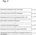
- obtaining the intermediate cranking signal based on the cranking signal and a window function comprises determining a minimum of the cranking signal; determining a maximum of the cranking signal between the first sample of the cranking signal and the determined minimum of the cranking signal; determining an endpoint of the cranking signal that corresponds to a sample number corresponding to a value that is equal to a predetermined coefficient multiplied by the determined maximum and the sample number is larger than the sample number corresponding to the determined minimum; wherein the window function is arranged to pass the samples between the determined maximum and the determined end point of the cranking signal and obtaining the intermediate cranking signal.
- the coefficient can be determined experimentally. A practical value is 0.9.
- the filtering of the intermediate signal comprises splitting the intermediate cranking signal in a first part comprising samples in the range between a maximum and a minimum and a second part comprising samples in the range between the minimum and an endpoint, filtering the first and second parts by a first and second digital filter respectively; and obtaining the filtered cranking signal by concatenating the filtered first and second parts.
- the first and second digital filter respectively, comprises a Saviki-Golay filter, wherein a frame length and a polynomial order of the respective filters can be selected differently depending on the characteristics of respective first and second part.
- the Saviky-Golay filter is a well-known digital filter for the person skilled in the art.
- the frame length and polynomial order can be differently selected depending on the variation of the values in the first and second part.
- the invention provides a device for determining a state of health of a battery in a vehicle according to claim 13.
- Fig. 1 is a block diagram of an internal structure of a device 10 or system comprising a user's computer in accordance with an exemplary embodiment of the present invention for determining a state of health of a battery 2 in a vehicle 1.
- the vehicle is provided with an engine 3 including a crank unit, a battery 2, an engine management system 4 and a vehicle communication device 5.
- the vehicle communication device 5 may comprise an on board diagnostic, device, OBD.
- OBD can be connected via a Bluetooth or Wi-Fi device to the device 10.
- the device 10 can be a personal computer, a smartphone, laptop or any other type of microprocessor based device.
- the device 10 may comprise a processor 11, an input device 12, a storage device 13, the storage device 13 can be a temporary storage device or permanent storage device and a first communication device 15 for connecting to the OBD 5.
- the first communication device 15 may include a modem, network interface card, or any other device able to transmit and receive signals to the vehicle communication device 5, for example Bluetooth or Wi-Fi.
- the input device 12 can be a key board, mouse, pen operated device and any other input device that provides input from a user.
- the device can further comprise a second communication device 16 and an output device 14.
- the second communication device 16 may include a modem, network interface card, or any other device able to communicate to the server 18 via the Internet 17.
- the output device 14 may be a monitor, speakers, printer or any other device that provides tangible output to a user.
- the temporary storage device may include RAM, caches, and any other volatile storage medium that temporarily holds data while processing it.
- the permanent storage device may include a solid state drive, hard drive, CD-ROM drive, tape drive, removable storage disk, or any other nonvolatile data storage medium.
- the temporality and permanent storage devices can store one or more of the determined parameters and values obtained during operation of the methods, described hereinafter.
- Fig. 2 shows a flow diagram according to an embodiment of the method for determining a state of health of the battery.
- a state of charge of the battery is determined.
- the state of charge can be determined by obtaining the open circuit voltage, OCV, of the battery after a predetermined rest period, wherein the vehicle is shut down and parked.
- the rest period can be for example 30 minutes.
- the thus obtained value proves to be a more accurate estimate of the OCV.
- the obtained value of the open circuit voltage is hereinafter called the rest value, RV.
- the RV is unique for a battery-vehicle combination. From the RV value a reference value can be obtained. A deviation from the reference value may indicate an insufficient state of charge of the battery.
- determining the state of charge of the battery may comprise the substeps of: Measuring the values of the resting voltage of the battery at plurality of instants at a fixed time interval in an initial state and a current state.
- the method of determining the state of health can be discontinued and a message can be output on the display 14, when the determined state of charge of the battery is poor and a reliable state of health of the battery cannot be obtained.
- a battery temperature can be obtained.
- the battery temperature is based on a combination of the engine coolant temperature, ambient temperature, device temperature a duration of last operation of a combustion engine, and time elapsed since last trip. These values can be obtained from the engine management unit via the communication interface and/or the OBD 5.
- a cranking temperature can be determined based on the engine coolant temperature, the ambient temperature, the device temperature and the time elapsed since the last trip. These values can also be obtained from the engine management unit via the communication interface and/or the OBD 5.
- a cranking signal can be obtained and can be a digital signal obtained during a cranking period by sampling the voltage of the battery, when the battery is discharged by the crank unit during one or more revolutions of the crank unit in the combustion engine during the cranking period.
- the cranking period is for example 1 sec.
- the sample frequency can be for example 200 Hz. So, according to this embodiment the cranking signal comprises 200 samples.
- the cranking signal can also be obtained from the communication device and/or the OBD.
- cranking type classes of the battery are determined based on the determined battery temperature and the determined cranking temperature.
- the advantage of using cranking type classes is that the inventors recognized that the cranking type classes may define sets of reference battery parameters that are specific for each vehicle, the battery temperature and cranking temperature.
- a cranking temperature signal can also obtained from the communication device or the OBD.
- the cranking type classes can be selected on basis of the determined battery temperature and determined cranking temperature.
- the number of cranking type classes can be for example 17.
- step 206 the battery parameters, for example the lowest voltage value, LVV, and the mean cranking voltage, MCV are obtained from the cranking signals corresponding to one or more cranking type classes.
- the step of determining the battery parameters for the one or more cranking type classes in the initial state comprises determining battery parameters after each of a plurality of consecutive crank periods from the cranking signals; and determining the battery parameters based on an average of the measured battery parameters. These steps can be repeated for the all the cranking type classes.
- the step of determining battery parameters from the obtained cranking signal comprises the substeps of determining an intermediate cranking signal from the cranking signal and a filtered cranking signal from the intermediate cranking signal and determining the battery parameters from the filtered cranking signal.
- Fig 3 shows a flow diagram of an embodiment method to determine a filtered cranking signal from the cranking signal.
- the cranking signal comprises N samples 1..N.
- the substeps for obtaining the filtered cranking signal from the cranking signal comprising:
- the coefficient ⁇ is 0.9. and the value c is 0.9b.
- This unique end point (Z, c) of the cranking signal is applied in a window function to obtain an intermediate cranking signal.
- Fig. 9 shows a graphical representation of the cranking signal.
- (X,a) represents a local minimum of the cranking signal 90
- (Y,b) represents a local maximum of the cranking signal
- (Z,c) represents a value c of sample Z, which sample number is determined between X and N in the cranking signal such that the value c equals 0.9 b.
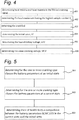
- Fig. 4 shows a flow diagram of an embodiment of the method to determine battery parameters from the filtered cranking signal.
- the substeps to determine the battery parameters comprises: Firstly determining a parameter crankEnd by the substeps:
- M represents the number of samples determined by S-L.
- the state of health of the battery can be based on a comparison of the battery parameters IV, LW, MCV in a historic or initial state and the determined parameters IV, LVV and MCV in the current state for the different cranking type classes from the filtered cranking signal.
- the determined values of these battery parameters can be stored in a table or database in a local memory 13 of the device 10 or in the data base server 18 which can be accessed by the device 10 through the Internet 17.
- An example of battery parameters IV, LVV and MCV are listed in table 1 for 17 cranking type classes.
- Table 1 table of cranking type classes and batteryparameters crankingTypeClass completed IV MCV LVV H1 FALSE H2 FALSE H3 FALSE H4 FALSE 12,17 9,79 8,03 H5 FALSE W1 FALSE W2 FALSE W3 FALSE 12,17 9,92 8,07 W4 TRUE 12,18 9,88 8,13 W5 FALSE C1 FALSE C2 FALSE 11,93 9,68 7,51 C3 TRUE 11,97 9,46 7,81 C4 TRUE 12,04 9,74 7,92 C5 FALSE N1 FALSE 12,13 8,05 9,81 etc.
- the values for IV, MCV and LW in Table 1 can be stored and updated in the data base after the cranking events in the corresponding cranking type class.
- Fig. 5 shows a flow diagram of a first embodiment of the method to determine a state of health from the battery parameters.
- the step of determining the state of health of the battery comprises the substeps:
- C 1 is a constant that can be experimentally determined and its value can be for example 0.8.
- the state of health of the battery is set to poor when the inequality is true.
- an indication of the state of health as poor indicates a high change of battery failure.
- an indication of the state of health as healthy indicates a new or freshly installed battery.
- the battery parameters of the initial state can be obtained from the local memory 13 or the database server 18.
- the device can output the determined state of health
- Fig 6 shows a graphical representation of a 2D-parameter field of the normalized LVV and the normalized MCV.
- Fig. 6 shows a separation line 601 indicating the separation between a healthy state and a poor state of the battery.
- the area including a point 602 above and right of the separation line indicates the healthy state.
- the area including a point 603 below and left of the separation line indicates the poor state.
- Fig. 7 shows a flow diagram of a second embodiment of the method for determining a state of health from the battery parameters.
- the step of determining the state of health of the battery in a cranking type class comprises the substeps:
- Fig. 8 shows a graphical representation of a 2D-parameter field for the unscaled MCV and the unscaled LVV.
- Fig. 8 shows an ellipsoid 801 indicating an area of a healthy state of the battery.
- Combined values of the MCV and the LVV in the lower left corner of the field, for example a point 803 correspond to a poor state of health of the battery.
- a point 802 in Fig. 8 corresponds to a still healthy state.
- step (208) the device can output the determined state of health of the battery as poor indicating a high change of battery failure.
- the present invention can be described as a method and apparatus for determining a state of health of a battery in a vehicle comprising determining (201) a state of charge of the battery; determining (202) a battery temperature, determining a cranking temperature based on the engine coolant temperature, the ambient temperature, the device temperature and the time elapsed since the last trip; obtaining (204) a cranking signal from the battery when the battery is discharged during cranking of a combustion engine of the vehicle; determining (205) one or more cranking type classes based on the determined battery temperature and the determined cranking temperature; determining (206) battery parameters from the cranking signal; determining (207) the state of health of the battery from the battery parameters, a vehicle identifier and historical battery parameters determined in a historic state preceding the current state; and outputting (206) the state of health, wherein determining the battery parameters from the cranking signal comprises applying a window function on the cranking signal to obtain an intermediate cranking signal, filtering the intermediate cranking signal and determining the battery parameters from the filtered cranking signal
Landscapes
- Engineering & Computer Science (AREA)
- Life Sciences & Earth Sciences (AREA)
- Sustainable Development (AREA)
- Sustainable Energy (AREA)
- Power Engineering (AREA)
- Transportation (AREA)
- Mechanical Engineering (AREA)
- Physics & Mathematics (AREA)
- General Physics & Mathematics (AREA)
- Secondary Cells (AREA)
- Tests Of Electric Status Of Batteries (AREA)
Claims (13)
- Verfahren zum Bestimmen eines Funktionszustands einer Batterie in einem Fahrzeug, das mit einer Brennkraftmaschine versehen ist, das die folgenden Schritte umfasst:a) Bestimmen (201) eines Ladezustands der Batterie;b) Bestimmen (202) einer Batterietemperatur;c) Bestimmen (203) einer Anlasstemperatur;d) Erhalten (204) eines Anlasssignals, das mehrere Abtastwerte der Batterie umfasst, wenn die Batterie während des Anlassens der Brennkraftmaschine entladen wird;e) Bestimmen (205) einer oder mehrerer Anlasstypklassen auf der Grundlage der bestimmten Batterietemperatur und der bestimmten Anlasstemperatur;f) Bestimmen (206) von Batterieparametern aus dem Anlasssignal, die der einen oder den mehreren bestimmten Anlasstypklassen entsprechen;g) Bestimmen (207) des Funktionszustands der Batterie für die eine oder die mehreren Anlasstypklassen aus den Batterieparametern, die entsprechend der Anlasstypklasse in einem Ist-Zustand bestimmt wurden, einer Fahrzeugkennung und Verlaufsbatterieparametern, die der einen oder den mehreren Anlasstypklassen, die in einem historischen Zustand, der dem Ist-Zustand vorangeht, bestimmt wurden, entsprechen; undh) Ausgeben (208) des Funktionszustands; wobei
das Bestimmen der Batterieparameter aus dem Anlasssignal Folgendes umfasst:Erhalten eines Zwischenanlasssignals;Filtern des Zwischenanlasssignals undBestimmen der Batterieparameter aus dem gefilterten Anlasssignal; wobeidas Verfahren dadurch gekennzeichnet ist, dass das Bestimmen einer Anlasstemperatur eine Kraftmaschinenkühlmitteltemperatur, eine Umgebungstemperatur, eine Kraftmaschinentemperatur und eine Zeit, die seit der letzten Fahrt verstrichen ist, als Grundlage verwendet und das Erhalten eines Zwischenanlasssignals das Anlasssignal und eine Fensterfunktion als Grundlage verwendet und Folgendes umfasst:Bestimmen (301) eines Minimums des Anlasssignals;Bestimmen (302) eines Maximums des Anlasssignals zwischen dem ersten Abtastwert des Anlasssignals und dem bestimmten Minimum des Anlasssignals undBestimmen (303) eines Endpunkts des Anlasssignals, der einer Abtastwertnummer entspricht, die einem Wert entspricht, der gleich einem vorgegebenen Koeffizienten multipliziert mit dem bestimmten Maximum ist und die Abtastwertnummer größer ist als die Abtastwertnummer, die dem bestimmten Minimum entspricht; wobeidie Fensterfunktion arrangiert ist, die Abtastwerte zwischen dem bestimmten Maximum und dem bestimmten Endpunkt des Anlasssignals durchzuleiten und die durchgeleiteten Abtastwerte als das Zwischenanlasssignal zu erhalten (304). - Verfahren nach Anspruch 1, wobei der historische Zustand einem Anfangszustand der Batterie entspricht.
- Verfahren nach Anspruch 2, wobei das Bestimmen des Funktionszustands ein Durchführen eines normierten Feldverfahrens an den Batterieparametern in dem Anfangszustand und dem Ist-Zustand in der Anlasstypklasse umfasst, wobei ein Bereich eines schlechten Zustands der Batterie zwei normierte Batterieparameter als Grundlage verwendet.
- Verfahren nach den Ansprüchen 2 und 3, wobei das Bestimmen der Batterieparameter für die eine oder die mehreren Anlasstypklassen im Anfangszustand Folgendes umfasst:a) Bestimmen der Batterieparameter nach jedem von mehreren aufeinanderfolgenden Anlasszeiträumen;b) Bestimmen der Batterieanfangsparameter auf der Grundlage eines Durchschnitts der gemessenen Batterieparameter undc) Wiederholen der Schritte 4.a) und 4.b) für jede der einen oder der mehreren Anlasstypklassen.
- Verfahren nach Anspruch 4, wobei die Batterieparameter eine Anfangsspannung, IV, einen niedrigsten Spannungswert, LVV, und eine Durchschnittsanlassspannung, MCV, umfassen.
- Verfahren nach Anspruch 1, wobei das Bestimmen des Funktionszustands Folgendes umfasst:Bestimmen (701) eines Gleitfensterdurchschnitts des Verlaufsbatterieparameters von mehreren historischen Zuständen in der Anlasstypklasse;Bestimmen (702) eines skalierten Batterieparameters auf der Grundlage des Batterieparameters, der in einem Ist-Zustand bestimmt wurde, und des bestimmten Gleitfensterdurchschnitts des Verlaufsbatterieparameters in der Anlasstypklasse; undBestimmen (703) des Funktionszustands im Ist-Zustand aus den skalierten Batterieparametern.
- Verfahren nach Anspruch 6, wobei der Gleitfensterdurchschnitt des Verlaufsbatterieparameters von einem ersten historischen Zustand N-30 zu einem zweiten historischen Zustand N-10 vor dem Ist-Zustand N in der Anlasstypklasse bestimmt wird.
- Verfahren nach Anspruch 6 oder 7, wobei die Batterieparameter einen niedrigsten Spannungswert, LVV, und eine Durchschnittsanlassspannung, MCV, umfassen.
- Verfahren nach Anspruch 1, wobei das Bestimmen des Ladezustands der Batterie Folgendes umfasst:Bestimmen einer Ruhespannung der Batterie nach einem Ruhezeitraum der Brennkraftmaschine;Bestimmen eines Bezugswerts für die Ruhespannung;Messen der Ruhespannung der Batterie in einem Ist-Zustand nach einer Betriebsdauer der Brennkraftmaschine;Bestimmen des Ladezustands der Batterie auf der Grundlage des Bezugsruhespannungswerts, des gemessenen Ruhewerts und der Betriebsdauer undEntscheiden abhängig vom Ladezustand der Batterie, die Bestimmung des Funktionszustands der Batterie fortzusetzen oder einzustellen.
- Verfahren nach Anspruch 1, wobei das Bestimmen der Batterietemperatur eine Kraftmaschinenkühlmitteltemperatur, eine Umgebungstemperatur, eine Kraftmaschinentemperatur, eine Dauer des letzten Betriebs der Brennkraftmaschine und eine seit dem letzten Betrieb verstrichene Zeit als Grundlage verwendet.
- Verfahren nach Anspruch 1, wobei das Filtern des Zwischenanlasssignals Folgendes umfasst:Unterteilen (305) des Zwischenanlasssignals in einen ersten Abschnitt, der Abtastwerte im Bereich zwischen einem Maximum und einem Minimum umfasst, und einen zweiten Abschnitt, der Abtastwerte im Bereich zwischen dem Minimum und einem Endpunkt des Zwischenanlasssignals umfasst;Filtern (306) des ersten und des zweiten Abschnitts durch ein erstes bzw. ein zweites digitales Filter undErhalten (307) des gefilterten Anlasssignals durch Verketten des gefilterten ersten und des gefilterten zweiten Abschnitts.
- Verfahren nach Anspruch 11, wobei das erste und das zweite digitale Filter jeweils ein Saviki-Golay-Filter umfassen und eine Rahmenlänge und eine Polynomordnung der jeweiligen Filter auf der Grundlage der Eigenschaften jeweiliger erster und zweiter Abschnitte verschieden sind.
- Vorrichtung zum Bestimmen eines Funktionszustands einer Batterie (2) in einem Fahrzeug (1), das mit einer Brennkraftmaschine versehen ist, und die Folgendes umfasst:eine Speichervorrichtung (13),eine Eingabevorrichtung (12);eine Ausgabevorrichtung (14), die eine Anzeigevorrichtung umfasst;eine Kommunikationsvorrichtung (15), die arrangiert ist, mit einem Steuersystem des Fahrzeugs zu kommunizieren, um eine Umgebungstemperatur; eine Leerlaufspannung der Batterie; eine Kraftmaschinenkühlmitteltemperatur und ein Anlasssignal, das mehrere Abtastwerte der Batterie umfasst, wenn die Batterie während des Anlassens einer Brennkraftmaschine des Fahrzeugs entladen wird, zu empfangen, undeine Steuereinheit (11), die arrangiert ist zuma) Bestimmen eines Ladezustands der Batterie;b) Bestimmen einer Batterietemperatur;c) Bestimmen einer Anlasstemperatur;e) Bestimmen einer oder mehrerer Anlasstypklassen auf der Grundlage der bestimmten Batterietemperatur und der bestimmten Anlasstemperatur;f) Bestimmen von Batterieparametern aus dem Anlasssignal, die der einen oder den mehreren bestimmten Anlasstypklassen entsprechen;g) Bestimmen des Funktionszustands der Batterie für eine oder mehrere Anlasstypklassen aus den Batterieparametern, die entsprechend der Anlasstypklasse in einem Ist-Zustand bestimmt wurden, einer Fahrzeugkennung und Verlaufsbatterieparametern, die der einen oder den mehreren Anlasstypklassen, die in einem historischen Zustand, der dem Ist-Zustand vorangeht, bestimmt wurden, entsprechen; undh) Ausgeben des Funktionszustands über die Ausgabevorrichtung; wobeidie Steuereinheit ferner arrangiert ist, die Batterieparameter aus dem Anlasssignal durch Erhalten eines Zwischenanlasssignals zu bestimmen;Filtern des Zwischenanlasssignals undBestimmen der Batterieparameter aus dem gefilterten Anlasssignal; dadurch gekennzeichnet, dassdie Steuereinheit arrangiert ist, die Anlasstemperatur auf der Grundlage der Kraftmaschinenkühlmitteltemperatur, der Umgebungstemperatur, der Kraftmaschinentemperatur und der Zeit, die seit der letzten Fahrt verstrichen ist, zu bestimmen; wobeidie Steuereinheit arrangiert ist, die Batterieparameter aus dem Anlasssignal durch Erhalten das Zwischenanlasssignal auf der Grundlage des Anlasssignals und einer Fensterfunktion zu bestimmen, was Folgendes umfasst:Bestimmen eines Minimums des Anlasssignals;Bestimmen eines Maximums des Anlasssignals zwischen dem ersten Abtastwert des Anlasssignals und dem bestimmten Minimum des Anlasssignals undBestimmen eines Endpunkts des Anlasssignals, der einer Abtastwertnummer entspricht, die einem Wert entspricht, der gleich einem vorgegebenen Koeffizienten multipliziert mit dem bestimmten Maximum ist, wobei die Abtastwertnummer größer ist als die Abtastwertnummer, die dem bestimmten Minimum entspricht; wobei die Fensterfunktion arrangiert ist, die Abtastwerte zwischen dem bestimmten Maximum und dem bestimmten Endpunkt des Anlasssignals durchzuleiten und die durchgeleiteten Abtastwerte als das Zwischenanlasssignal zu erhalten.
Applications Claiming Priority (2)
| Application Number | Priority Date | Filing Date | Title |
|---|---|---|---|
| NL2019831A NL2019831B1 (en) | 2017-10-30 | 2017-10-30 | Method and apparatus for indicating a state of health of a battery |
| PCT/NL2018/050722 WO2019088830A1 (en) | 2017-10-30 | 2018-10-30 | Method and apparatus for indicating a state of health of a battery |
Publications (2)
| Publication Number | Publication Date |
|---|---|
| EP3704505A1 EP3704505A1 (de) | 2020-09-09 |
| EP3704505B1 true EP3704505B1 (de) | 2021-08-04 |
Family
ID=60382569
Family Applications (1)
| Application Number | Title | Priority Date | Filing Date |
|---|---|---|---|
| EP18812383.0A Active EP3704505B1 (de) | 2017-10-30 | 2018-10-30 | Verfahren und vorrichtung zur anzeige eines gesundheitszustands einer batterie |
Country Status (6)
| Country | Link |
|---|---|
| US (1) | US11203273B2 (de) |
| EP (1) | EP3704505B1 (de) |
| CN (1) | CN111373275B (de) |
| ES (1) | ES2894845T3 (de) |
| NL (1) | NL2019831B1 (de) |
| WO (1) | WO2019088830A1 (de) |
Families Citing this family (14)
| Publication number | Priority date | Publication date | Assignee | Title |
|---|---|---|---|---|
| EP4708233A3 (de) | 2018-02-08 | 2026-05-06 | GEOTAB Inc. | Telematische überwachung eines zustands einer operativen fahrzeugkomponente |
| US11731867B2 (en) * | 2019-05-28 | 2023-08-22 | Vehicle Service Group, Llc | System for vehicle lift monitoring and prognostics |
| KR102842049B1 (ko) * | 2019-06-28 | 2025-08-04 | 주식회사 엘지에너지솔루션 | 불량 배터리 셀 검출 장치 및 방법 |
| EP3786904B1 (de) * | 2019-08-27 | 2025-02-26 | GEOTAB Inc. | Verfahren zur telematischen bereitstellung von fahrzeugkomponentenbewertung |
| FR3101430B1 (fr) * | 2019-09-27 | 2021-09-03 | Continental Automotive | Procédé d’estimation du vieillissement d’une batterie d’un véhicule |
| EP3835115A1 (de) * | 2019-12-12 | 2021-06-16 | Permobil AB | Verfahren zum schätzen der verbleibenden fahrdistanz, die von einer ladung für eine angetriebene mobilitätsvorrichtung verfügbar ist |
| CN112744087B (zh) | 2020-04-08 | 2022-02-25 | 长城汽车股份有限公司 | 环境温度确定方法、电机控制器、控制系统及存储介质 |
| CN111873999B (zh) * | 2020-07-16 | 2021-12-31 | 上海星融汽车科技有限公司 | 车辆蓄电池电量监测系统及其车辆 |
| EP4246158B1 (de) * | 2022-03-15 | 2024-09-04 | Ningbo Geely Automobile Research & Development Co. Ltd. | Verfahren zur schätzung der batterieversorgungsspannung |
| CN114646888B (zh) * | 2022-03-17 | 2025-09-09 | 彩虹无线(北京)新技术有限公司 | 一种动力电池容量衰减的评估方法及系统 |
| CN114843558B (zh) * | 2022-05-20 | 2023-07-21 | 上海捷氢科技股份有限公司 | 一种燃料电池运行特性确定方法和装置 |
| CN115308629B (zh) * | 2022-08-23 | 2024-08-13 | 中国第一汽车股份有限公司 | 电池性能的测试方法、装置、存储介质及电子设备 |
| CN115635882B (zh) * | 2022-11-07 | 2024-11-19 | 上海机动车检测认证技术研究中心有限公司 | 动力电池异常评估方法、评估设备及计算机可读存储介质 |
| CN116500465B (zh) * | 2023-05-10 | 2025-06-17 | 赛力斯汽车有限公司 | 基于汽车电池参数实现电池监测方法及系统 |
Family Cites Families (22)
| Publication number | Priority date | Publication date | Assignee | Title |
|---|---|---|---|---|
| FR2769095B1 (fr) * | 1997-10-01 | 1999-11-26 | Siemens Automotive Sa | Procede de detection de defaillance d'une batterie de vehicule automobile |
| DE19750309A1 (de) * | 1997-11-13 | 1999-05-20 | Vb Autobatterie Gmbh | Verfahren zur Bestimmung der Startfähigkeit der Starterbatterie eines Kraftfahrzeugs |
| US6469512B2 (en) * | 2000-01-12 | 2002-10-22 | Honeywell International Inc. | System and method for determining battery state-of-health |
| US6369578B1 (en) * | 2001-06-05 | 2002-04-09 | Delphi Technologies, Inc. | State of health for automotive batteries |
| US6727708B1 (en) * | 2001-12-06 | 2004-04-27 | Johnson Controls Technology Company | Battery monitoring system |
| DE10394007T5 (de) * | 2002-12-31 | 2006-02-02 | Midtronics, Inc., Willowbrook | Vorrichtung und Verfahren zum Vorhersagen der verbleibenden Entladezeit einer Batterie |
| US7545109B2 (en) * | 2006-12-22 | 2009-06-09 | Gm Global Technology Operations, Inc. | Method and apparatus for monitoring an electrical energy storage device |
| US7983862B2 (en) * | 2008-04-22 | 2011-07-19 | GM Global Technology Operations LLC | Battery state-of-health monitoring system and method |
| US8972213B2 (en) * | 2008-06-27 | 2015-03-03 | GM Global Technology Operations LLC | Pattern recognition approach to battery diagnosis and prognosis |
| US8111037B2 (en) * | 2008-06-27 | 2012-02-07 | GM Global Technology Operations LLC | Method for battery state-of-health monitoring using battery voltage during vehicle starting |
| US8212527B2 (en) * | 2008-07-29 | 2012-07-03 | GM Global Technology Operations LLC | Method and apparatus for telematics-based vehicle no-start prognosis |
| US7743649B1 (en) * | 2008-12-18 | 2010-06-29 | Gm Global Technology Operations, Inc. | Cranking capability estimation for a vehicular starting system |
| US20110082621A1 (en) * | 2009-10-02 | 2011-04-07 | Eric Berkobin | Method and system for predicting battery life based on vehicle battery, usage, and environmental data |
| KR20120004670A (ko) * | 2010-07-07 | 2012-01-13 | 인셀스(주) | 차량용 배터리 센서 |
| US8818611B2 (en) | 2011-08-15 | 2014-08-26 | GM Global Technology Operations LLC | Method and apparatus to evaluate a starting system for an internal combustion engine |
| US9086462B2 (en) * | 2012-08-15 | 2015-07-21 | GM Global Technology Operations LLC | Systems and methods for battery parameter estimation |
| WO2014098837A1 (en) * | 2012-12-19 | 2014-06-26 | Schneider Electric USA, Inc. | Battery voltage profile monitoring during generator start |
| US9404466B2 (en) * | 2014-06-14 | 2016-08-02 | GM Global Technology Operations LLC | Method for evaluating an engine starting system |
| GB2537612B (en) * | 2015-04-20 | 2018-05-23 | Trakm8 Ltd | Monitoring the health of a vehicle battery |
| US9816475B1 (en) * | 2016-05-11 | 2017-11-14 | Cooper Technologies Company | System and method for maximizing short-term energy storage in a supercapacitor array for engine start applications |
| TWI622780B (zh) * | 2016-11-28 | 2018-05-01 | Dhc Specialty Corp | Asymmetric battery detection device |
| US10144306B2 (en) * | 2017-01-18 | 2018-12-04 | Ford Global Technologies, Llc | Battery health evaluation |
-
2017
- 2017-10-30 NL NL2019831A patent/NL2019831B1/en not_active IP Right Cessation
-
2018
- 2018-10-30 ES ES18812383T patent/ES2894845T3/es active Active
- 2018-10-30 EP EP18812383.0A patent/EP3704505B1/de active Active
- 2018-10-30 CN CN201880070598.8A patent/CN111373275B/zh active Active
- 2018-10-30 WO PCT/NL2018/050722 patent/WO2019088830A1/en not_active Ceased
- 2018-10-30 US US16/759,850 patent/US11203273B2/en active Active
Also Published As
| Publication number | Publication date |
|---|---|
| WO2019088830A1 (en) | 2019-05-09 |
| EP3704505A1 (de) | 2020-09-09 |
| US20200331359A1 (en) | 2020-10-22 |
| US11203273B2 (en) | 2021-12-21 |
| CN111373275A (zh) | 2020-07-03 |
| NL2019831B1 (en) | 2019-05-08 |
| ES2894845T3 (es) | 2022-02-16 |
| CN111373275B (zh) | 2023-05-26 |
Similar Documents
| Publication | Publication Date | Title |
|---|---|---|
| EP3704505B1 (de) | Verfahren und vorrichtung zur anzeige eines gesundheitszustands einer batterie | |
| KR102837694B1 (ko) | 배터리 진단 장치, 배터리 진단 방법, 배터리 팩 및 자동차 | |
| CN102656469B (zh) | 一种用于持续测量安装在车辆内的电池效率的方法以及设备 | |
| JP6026120B2 (ja) | 二次電池の内部抵抗演算装置及びその内部抵抗演算方法、二次電池の異常検出装置及びその異常検出方法、並びに二次電池の劣化推定装置及びその劣化推定方法 | |
| US20090146664A1 (en) | Battery state of health monitoring system and method | |
| CN100575979C (zh) | 用于预测电蓄能器的剩余寿命的方法 | |
| US20220140617A1 (en) | Drooping cell detection and state of cell health monitoring | |
| JPWO2016129248A1 (ja) | 二次電池の充電状態推定装置および充電状態推定方法 | |
| JP2018147680A (ja) | 温度異常判定装置、温度異常判定方法及びコンピュータプログラム | |
| JP2025502294A (ja) | バッテリー診断装置、バッテリーの診断方法、バッテリーパック及び自動車 | |
| CN117849629A (zh) | 电池析锂检测方法、装置及电子设备 | |
| CN116125300B (zh) | 一种电池包异常监测方法、装置、电子设备及存储介质 | |
| HK40037502A (en) | Method and apparatus for indicating a state of health of a battery | |
| HK40037502B (en) | Method and apparatus for indicating a state of health of a battery | |
| EP3835800B1 (de) | Diagnose von energiespeichersystemen in betrieb | |
| CN113408739A (zh) | 定子温度的监控方法、装置、设备和存储介质 | |
| EP4678457A1 (de) | Elektrofahrzeugladevorrichtung zum sicheren und effizienten laden eines elektrofahrzeugs mit brandschutzfunktion und batterieleistungsbeurteilungsfunktion | |
| CN119575200A (zh) | 一种适用于间歇性丢数据场景下的电池容量修正方法 | |
| CN117668498A (zh) | 基于可靠性分布和异常探测的泵健康评估方法 | |
| CN116930763A (zh) | 一种基于雨流计数法的电池剩余容量检测方法及应用 | |
| WO2022089846A1 (en) | A method to monitor battery health of a vehicle | |
| CN116794548A (zh) | 电池故障预警和诊断方法 | |
| US20250172628A1 (en) | Method and device for detecting a failure of a lithium-ion battery cell | |
| CN118033465B (zh) | 电池自放电异常识别方法、装置、车辆及存储介质 | |
| CN113009363A (zh) | 用于测量电池欧姆电阻的方法和装置 |
Legal Events
| Date | Code | Title | Description |
|---|---|---|---|
| STAA | Information on the status of an ep patent application or granted ep patent |
Free format text: STATUS: UNKNOWN |
|
| STAA | Information on the status of an ep patent application or granted ep patent |
Free format text: STATUS: THE INTERNATIONAL PUBLICATION HAS BEEN MADE |
|
| PUAI | Public reference made under article 153(3) epc to a published international application that has entered the european phase |
Free format text: ORIGINAL CODE: 0009012 |
|
| STAA | Information on the status of an ep patent application or granted ep patent |
Free format text: STATUS: REQUEST FOR EXAMINATION WAS MADE |
|
| 17P | Request for examination filed |
Effective date: 20200414 |
|
| AK | Designated contracting states |
Kind code of ref document: A1 Designated state(s): AL AT BE BG CH CY CZ DE DK EE ES FI FR GB GR HR HU IE IS IT LI LT LU LV MC MK MT NL NO PL PT RO RS SE SI SK SM TR |
|
| AX | Request for extension of the european patent |
Extension state: BA ME |
|
| DAV | Request for validation of the european patent (deleted) | ||
| DAX | Request for extension of the european patent (deleted) | ||
| GRAP | Despatch of communication of intention to grant a patent |
Free format text: ORIGINAL CODE: EPIDOSNIGR1 |
|
| STAA | Information on the status of an ep patent application or granted ep patent |
Free format text: STATUS: GRANT OF PATENT IS INTENDED |
|
| RIC1 | Information provided on ipc code assigned before grant |
Ipc: B60L 58/16 20190101ALI20210224BHEP Ipc: B60L 58/10 20190101ALI20210224BHEP Ipc: G01R 31/392 20190101AFI20210224BHEP |
|
| INTG | Intention to grant announced |
Effective date: 20210315 |
|
| REG | Reference to a national code |
Ref country code: HK Ref legal event code: DE Ref document number: 40037502 Country of ref document: HK |
|
| GRAS | Grant fee paid |
Free format text: ORIGINAL CODE: EPIDOSNIGR3 |
|
| GRAA | (expected) grant |
Free format text: ORIGINAL CODE: 0009210 |
|
| STAA | Information on the status of an ep patent application or granted ep patent |
Free format text: STATUS: THE PATENT HAS BEEN GRANTED |
|
| AK | Designated contracting states |
Kind code of ref document: B1 Designated state(s): AL AT BE BG CH CY CZ DE DK EE ES FI FR GB GR HR HU IE IS IT LI LT LU LV MC MK MT NL NO PL PT RO RS SE SI SK SM TR |
|
| REG | Reference to a national code |
Ref country code: GB Ref legal event code: FG4D |
|
| REG | Reference to a national code |
Ref country code: AT Ref legal event code: REF Ref document number: 1417508 Country of ref document: AT Kind code of ref document: T Effective date: 20210815 |
|
| REG | Reference to a national code |
Ref country code: CH Ref legal event code: EP |
|
| REG | Reference to a national code |
Ref country code: DE Ref legal event code: R096 Ref document number: 602018021380 Country of ref document: DE |
|
| REG | Reference to a national code |
Ref country code: IE Ref legal event code: FG4D |
|
| REG | Reference to a national code |
Ref country code: NL Ref legal event code: FP |
|
| REG | Reference to a national code |
Ref country code: SE Ref legal event code: TRGR |
|
| REG | Reference to a national code |
Ref country code: LT Ref legal event code: MG9D |
|
| PG25 | Lapsed in a contracting state [announced via postgrant information from national office to epo] |
Ref country code: RS Free format text: LAPSE BECAUSE OF FAILURE TO SUBMIT A TRANSLATION OF THE DESCRIPTION OR TO PAY THE FEE WITHIN THE PRESCRIBED TIME-LIMIT Effective date: 20210804 Ref country code: FI Free format text: LAPSE BECAUSE OF FAILURE TO SUBMIT A TRANSLATION OF THE DESCRIPTION OR TO PAY THE FEE WITHIN THE PRESCRIBED TIME-LIMIT Effective date: 20210804 Ref country code: LT Free format text: LAPSE BECAUSE OF FAILURE TO SUBMIT A TRANSLATION OF THE DESCRIPTION OR TO PAY THE FEE WITHIN THE PRESCRIBED TIME-LIMIT Effective date: 20210804 Ref country code: BG Free format text: LAPSE BECAUSE OF FAILURE TO SUBMIT A TRANSLATION OF THE DESCRIPTION OR TO PAY THE FEE WITHIN THE PRESCRIBED TIME-LIMIT Effective date: 20211104 Ref country code: HR Free format text: LAPSE BECAUSE OF FAILURE TO SUBMIT A TRANSLATION OF THE DESCRIPTION OR TO PAY THE FEE WITHIN THE PRESCRIBED TIME-LIMIT Effective date: 20210804 Ref country code: NO Free format text: LAPSE BECAUSE OF FAILURE TO SUBMIT A TRANSLATION OF THE DESCRIPTION OR TO PAY THE FEE WITHIN THE PRESCRIBED TIME-LIMIT Effective date: 20211104 Ref country code: PT Free format text: LAPSE BECAUSE OF FAILURE TO SUBMIT A TRANSLATION OF THE DESCRIPTION OR TO PAY THE FEE WITHIN THE PRESCRIBED TIME-LIMIT Effective date: 20211206 |
|
| REG | Reference to a national code |
Ref country code: ES Ref legal event code: FG2A Ref document number: 2894845 Country of ref document: ES Kind code of ref document: T3 Effective date: 20220216 |
|
| PG25 | Lapsed in a contracting state [announced via postgrant information from national office to epo] |
Ref country code: PL Free format text: LAPSE BECAUSE OF FAILURE TO SUBMIT A TRANSLATION OF THE DESCRIPTION OR TO PAY THE FEE WITHIN THE PRESCRIBED TIME-LIMIT Effective date: 20210804 Ref country code: LV Free format text: LAPSE BECAUSE OF FAILURE TO SUBMIT A TRANSLATION OF THE DESCRIPTION OR TO PAY THE FEE WITHIN THE PRESCRIBED TIME-LIMIT Effective date: 20210804 Ref country code: GR Free format text: LAPSE BECAUSE OF FAILURE TO SUBMIT A TRANSLATION OF THE DESCRIPTION OR TO PAY THE FEE WITHIN THE PRESCRIBED TIME-LIMIT Effective date: 20211105 |
|
| PG25 | Lapsed in a contracting state [announced via postgrant information from national office to epo] |
Ref country code: DK Free format text: LAPSE BECAUSE OF FAILURE TO SUBMIT A TRANSLATION OF THE DESCRIPTION OR TO PAY THE FEE WITHIN THE PRESCRIBED TIME-LIMIT Effective date: 20210804 |
|
| REG | Reference to a national code |
Ref country code: DE Ref legal event code: R097 Ref document number: 602018021380 Country of ref document: DE |
|
| REG | Reference to a national code |
Ref country code: CH Ref legal event code: PL |
|
| PG25 | Lapsed in a contracting state [announced via postgrant information from national office to epo] |
Ref country code: SM Free format text: LAPSE BECAUSE OF FAILURE TO SUBMIT A TRANSLATION OF THE DESCRIPTION OR TO PAY THE FEE WITHIN THE PRESCRIBED TIME-LIMIT Effective date: 20210804 Ref country code: SK Free format text: LAPSE BECAUSE OF FAILURE TO SUBMIT A TRANSLATION OF THE DESCRIPTION OR TO PAY THE FEE WITHIN THE PRESCRIBED TIME-LIMIT Effective date: 20210804 Ref country code: RO Free format text: LAPSE BECAUSE OF FAILURE TO SUBMIT A TRANSLATION OF THE DESCRIPTION OR TO PAY THE FEE WITHIN THE PRESCRIBED TIME-LIMIT Effective date: 20210804 Ref country code: EE Free format text: LAPSE BECAUSE OF FAILURE TO SUBMIT A TRANSLATION OF THE DESCRIPTION OR TO PAY THE FEE WITHIN THE PRESCRIBED TIME-LIMIT Effective date: 20210804 Ref country code: CZ Free format text: LAPSE BECAUSE OF FAILURE TO SUBMIT A TRANSLATION OF THE DESCRIPTION OR TO PAY THE FEE WITHIN THE PRESCRIBED TIME-LIMIT Effective date: 20210804 Ref country code: AL Free format text: LAPSE BECAUSE OF FAILURE TO SUBMIT A TRANSLATION OF THE DESCRIPTION OR TO PAY THE FEE WITHIN THE PRESCRIBED TIME-LIMIT Effective date: 20210804 |
|
| PLBE | No opposition filed within time limit |
Free format text: ORIGINAL CODE: 0009261 |
|
| STAA | Information on the status of an ep patent application or granted ep patent |
Free format text: STATUS: NO OPPOSITION FILED WITHIN TIME LIMIT |
|
| PG25 | Lapsed in a contracting state [announced via postgrant information from national office to epo] |
Ref country code: MC Free format text: LAPSE BECAUSE OF FAILURE TO SUBMIT A TRANSLATION OF THE DESCRIPTION OR TO PAY THE FEE WITHIN THE PRESCRIBED TIME-LIMIT Effective date: 20210804 |
|
| 26N | No opposition filed |
Effective date: 20220506 |
|
| PG25 | Lapsed in a contracting state [announced via postgrant information from national office to epo] |
Ref country code: SI Free format text: LAPSE BECAUSE OF FAILURE TO SUBMIT A TRANSLATION OF THE DESCRIPTION OR TO PAY THE FEE WITHIN THE PRESCRIBED TIME-LIMIT Effective date: 20210804 Ref country code: LI Free format text: LAPSE BECAUSE OF NON-PAYMENT OF DUE FEES Effective date: 20211031 Ref country code: CH Free format text: LAPSE BECAUSE OF NON-PAYMENT OF DUE FEES Effective date: 20211031 |
|
| PG25 | Lapsed in a contracting state [announced via postgrant information from national office to epo] |
Ref country code: IE Free format text: LAPSE BECAUSE OF NON-PAYMENT OF DUE FEES Effective date: 20211030 |
|
| REG | Reference to a national code |
Ref country code: AT Ref legal event code: UEP Ref document number: 1417508 Country of ref document: AT Kind code of ref document: T Effective date: 20210804 |
|
| PG25 | Lapsed in a contracting state [announced via postgrant information from national office to epo] |
Ref country code: CY Free format text: LAPSE BECAUSE OF FAILURE TO SUBMIT A TRANSLATION OF THE DESCRIPTION OR TO PAY THE FEE WITHIN THE PRESCRIBED TIME-LIMIT Effective date: 20210804 |
|
| PG25 | Lapsed in a contracting state [announced via postgrant information from national office to epo] |
Ref country code: HU Free format text: LAPSE BECAUSE OF FAILURE TO SUBMIT A TRANSLATION OF THE DESCRIPTION OR TO PAY THE FEE WITHIN THE PRESCRIBED TIME-LIMIT; INVALID AB INITIO Effective date: 20181030 |
|
| PG25 | Lapsed in a contracting state [announced via postgrant information from national office to epo] |
Ref country code: MK Free format text: LAPSE BECAUSE OF FAILURE TO SUBMIT A TRANSLATION OF THE DESCRIPTION OR TO PAY THE FEE WITHIN THE PRESCRIBED TIME-LIMIT Effective date: 20210804 |
|
| PG25 | Lapsed in a contracting state [announced via postgrant information from national office to epo] |
Ref country code: TR Free format text: LAPSE BECAUSE OF FAILURE TO SUBMIT A TRANSLATION OF THE DESCRIPTION OR TO PAY THE FEE WITHIN THE PRESCRIBED TIME-LIMIT Effective date: 20210804 |
|
| PG25 | Lapsed in a contracting state [announced via postgrant information from national office to epo] |
Ref country code: MT Free format text: LAPSE BECAUSE OF FAILURE TO SUBMIT A TRANSLATION OF THE DESCRIPTION OR TO PAY THE FEE WITHIN THE PRESCRIBED TIME-LIMIT Effective date: 20210804 |
|
| PGFP | Annual fee paid to national office [announced via postgrant information from national office to epo] |
Ref country code: LU Payment date: 20251024 Year of fee payment: 8 Ref country code: NL Payment date: 20251021 Year of fee payment: 8 |
|
| PGFP | Annual fee paid to national office [announced via postgrant information from national office to epo] |
Ref country code: DE Payment date: 20251028 Year of fee payment: 8 |
|
| PGFP | Annual fee paid to national office [announced via postgrant information from national office to epo] |
Ref country code: GB Payment date: 20251027 Year of fee payment: 8 |
|
| PGFP | Annual fee paid to national office [announced via postgrant information from national office to epo] |
Ref country code: AT Payment date: 20251027 Year of fee payment: 8 |
|
| PGFP | Annual fee paid to national office [announced via postgrant information from national office to epo] |
Ref country code: IT Payment date: 20251027 Year of fee payment: 8 |
|
| PGFP | Annual fee paid to national office [announced via postgrant information from national office to epo] |
Ref country code: FR Payment date: 20251027 Year of fee payment: 8 |
|
| PGFP | Annual fee paid to national office [announced via postgrant information from national office to epo] |
Ref country code: BE Payment date: 20251024 Year of fee payment: 8 |
|
| PGFP | Annual fee paid to national office [announced via postgrant information from national office to epo] |
Ref country code: SE Payment date: 20251024 Year of fee payment: 8 |
|
| PGFP | Annual fee paid to national office [announced via postgrant information from national office to epo] |
Ref country code: ES Payment date: 20251118 Year of fee payment: 8 |