EP3704043B1 - Vorrichtung, systeme und verfahren zur überwachung von förderbandrollen - Google Patents
Vorrichtung, systeme und verfahren zur überwachung von förderbandrollen Download PDFInfo
- Publication number
- EP3704043B1 EP3704043B1 EP18873288.7A EP18873288A EP3704043B1 EP 3704043 B1 EP3704043 B1 EP 3704043B1 EP 18873288 A EP18873288 A EP 18873288A EP 3704043 B1 EP3704043 B1 EP 3704043B1
- Authority
- EP
- European Patent Office
- Prior art keywords
- idler
- conveyor
- monitoring system
- application server
- optionally
- Prior art date
- Legal status (The legal status is an assumption and is not a legal conclusion. Google has not performed a legal analysis and makes no representation as to the accuracy of the status listed.)
- Active
Links
Images


Classifications
-
- B—PERFORMING OPERATIONS; TRANSPORTING
- B65—CONVEYING; PACKING; STORING; HANDLING THIN OR FILAMENTARY MATERIAL
- B65G—TRANSPORT OR STORAGE DEVICES, e.g. CONVEYORS FOR LOADING OR TIPPING, SHOP CONVEYOR SYSTEMS OR PNEUMATIC TUBE CONVEYORS
- B65G43/00—Control devices, e.g. for safety, warning or fault-correcting
- B65G43/02—Control devices, e.g. for safety, warning or fault-correcting detecting dangerous physical condition of load carriers, e.g. for interrupting the drive in the event of overheating
-
- G—PHYSICS
- G01—MEASURING; TESTING
- G01K—MEASURING TEMPERATURE; MEASURING QUANTITY OF HEAT; THERMALLY-SENSITIVE ELEMENTS NOT OTHERWISE PROVIDED FOR
- G01K13/00—Thermometers specially adapted for specific purposes
-
- B—PERFORMING OPERATIONS; TRANSPORTING
- B65—CONVEYING; PACKING; STORING; HANDLING THIN OR FILAMENTARY MATERIAL
- B65G—TRANSPORT OR STORAGE DEVICES, e.g. CONVEYORS FOR LOADING OR TIPPING, SHOP CONVEYOR SYSTEMS OR PNEUMATIC TUBE CONVEYORS
- B65G39/00—Rollers, e.g. drive rollers, or arrangements thereof incorporated in roller-ways or other types of mechanical conveyors
-
- G—PHYSICS
- G01—MEASURING; TESTING
- G01G—WEIGHING
- G01G23/00—Auxiliary devices for weighing apparatus
- G01G23/18—Indicating devices, e.g. for remote indication; Recording devices; Scales, e.g. graduated
- G01G23/36—Indicating the weight by electrical means, e.g. using photoelectric cells
-
- G—PHYSICS
- G01—MEASURING; TESTING
- G01J—MEASUREMENT OF INTENSITY, VELOCITY, SPECTRAL CONTENT, POLARISATION, PHASE OR PULSE CHARACTERISTICS OF INFRARED, VISIBLE OR ULTRAVIOLET LIGHT; COLORIMETRY; RADIATION PYROMETRY
- G01J5/00—Radiation pyrometry, e.g. infrared or optical thermometry
-
- G—PHYSICS
- G01—MEASURING; TESTING
- G01K—MEASURING TEMPERATURE; MEASURING QUANTITY OF HEAT; THERMALLY-SENSITIVE ELEMENTS NOT OTHERWISE PROVIDED FOR
- G01K1/00—Details of thermometers not specially adapted for particular types of thermometer
- G01K1/02—Means for indicating or recording specially adapted for thermometers
- G01K1/024—Means for indicating or recording specially adapted for thermometers for remote indication
-
- G—PHYSICS
- G01—MEASURING; TESTING
- G01M—TESTING STATIC OR DYNAMIC BALANCE OF MACHINES OR STRUCTURES; TESTING OF STRUCTURES OR APPARATUS, NOT OTHERWISE PROVIDED FOR
- G01M13/00—Testing of machine parts
- G01M13/04—Bearings
Definitions
- the current disclosure concerns a conveyor idler monitoring apparatus.
- a known apparatus is shown in ITUB20155386A1, which discloses the preamble of claim 1 and describes a control system of a conveyor comprising rollers, each of said rollers comprising at least one sensor which provides a signal indicative of at least one physical parameter of said roller; and a transmitter capable of transmitting said signal.
- An identification number is associated with each of said rollers; said transmitter being able to transmit said identification number.
- the control system comprises an interrogator adapted to feed said roller transmitter of said plurality of rollers; said transmitter of a roller of said plurality of rollers fed by said interrogator, sends said signal and said identification number to said interrogator.
- the problem is therefore to improve the efficiency of the maintenance of such systems.
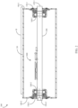
- FIGs. 1 and 2 illustrate an embodiment of a conveyor idler 100.
- the conveyor idler 100 includes a cylinder 130 rollingly supported on a shaft 200.
- the shaft 200 is supported (e.g., in a stationary manner) on a conveyor.
- the cylinder 130 is configured to at least partially support a conveyor belt B.
- the idler 100 optionally includes end discs 140-1, 140-2 disposed at opposing ends of the shaft 200 and mounted to opposing ends 220-1, 220-2 of the cylinder 130. Each end disc is optionally supported on an associated bearing 160 (e.g., ball bearing). A seal assembly 150 is optionally disposed outboard of each bearing assembly to at least partially prevent external liquid and/or debris from entering an interior volume of the idler 100.
- a monitoring system 600 (e.g., one of the monitoring system embodiments described herein) is optionally at least partially supported on the shaft 200.
- one or more mounting boards 260, 262 are optionally mounted to the shaft 200 for supporting one or more electronic components of the monitoring system 600.
- a load sensor 500 is supported on (e.g., mounted to the shaft 200).
- a cavity 250 is provided in an end 220 of the shaft 200 for housing a transmitter and/or other components of the monitoring system.
- An opening 230 is optionally provided in the shaft for at least partially receiving one or more electrical connectors (e.g., wire, cable, etc.) which optionally connect the transmitter to the load sensor 500 and/or other components supported on the shaft 200 (e.g., on mounting board 260).
- a transmitter is at least partially received in the cavity 250.
- a cavity 250 may be omitted and the transmitter is optionally mounted on the end 220 of the shaft or elsewhere on the idler and/or conveyor.
- one or more cavities 240 are provided adjacent to (e.g., radially inward of) the bearing 160. In some embodiments, each cavity 240 is provided in a radially outer surface of the shaft 200. In some embodiments, a temperature sensor 635 (e.g., resistance temperature detector, thermocouple, etc.) is at least partially received in one or more cavities 240.
- a temperature sensor 635 e.g., resistance temperature detector, thermocouple, etc.
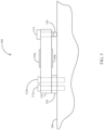
- the load sensor 500 optionally includes a deflector arm 510.
- One or more strain gauges 550 are optionally mounted to the deflector arm (e.g., in a Wheatstone bridge or other arrangement).
- the deflector arm 510 is optionally mounted to the shaft 200 (e.g., an upper surface of the shaft, disposed between the shaft and the conveyor belt, etc.) such as by one or more bolts 512.
- the deflector arm 510 is optionally spaced apart (e.g., vertically spaced apart) from the shaft 200 by a spacer 520.
- a bolt 514 or other apparatus optionally applies a load between the deflector arm 510 and the shaft 200.
- a rounded lower surface 530 (e.g., a ball) optionally at least partially transfers a load between the deflector arm 510 and the shaft 200.
- the bolt 514 is optionally adjustable in order to increase or decrease the load on the lower surface 530.
- the rounded lower surface 530 is optionally located at or near an axial midpoint of the shaft 200 (e.g., at or near a location equidistant to the ends 220-1, 220-2).
- Deflection of the shaft 200 optionally changes a deflection of the deflector arm 510 such that one or more strain gauges 550 generate a modified strain signal related to the amount of deflection of the shaft 200.
- the load sensor 500 (e.g., a load cell and/or strain gauge thereof) is optionally in data communication with a processor 625 (e.g., optionally via an amplifier 640 which is optionally configured to convert an analog signal to a digital signal).
- a processor 625 e.g., optionally via an amplifier 640 which is optionally configured to convert an analog signal to a digital signal.
- One or more temperature sensors 635 are optionally in data communication with the processor 625.
- a vibration sensor 620 (e.g., optionally mounted to the shaft 200) is optionally in data communication with the processor 625.
- a real time clock 630 is optionally in data communication with the processor 625.
- the processor 625 optionally transmits signals (e.g., at least partially processed signals) from the various sensors to a processor 610 in data communication with the processor 625.
- the processor 610 is optionally in data communication with a memory 615 (e.g., SD card or other memory).
- the processor 610 is optionally in fluid communication with a transmitter 605 (e.g., antenna).
- the transmitter 605 optionally comprises a wireless transmitter (e.g., a WiFi interface access point).
- the transmitter 605 is optionally at least partially disposed in the cavity 250.
- the transmitter 605 is optionally in data communication (e.g., wireless communication) with a monitor 690.
- the monitor 690 optionally comprises a graphical user interface.
- the monitor 690 comprises a mobile computing device such as a consumer computing device (e.g., smart phone, tablet, laptop, etc.).
- the idler 800 is optionally generally similar to one or more of the other idler embodiments described herein; in some embodiments the idler 800 includes an optionally modified shaft 200' rollingly supporting the cylinder 130.
- An optionally modified cavity 250' (e.g., in or adjacent to shaft 200') optionally at least partially houses a transmitter 605.
- the idler 800 optionally includes an identifier 810 (e.g., RFID tag or QR code) which may be provided at or adjacent to the end of shaft 200'.
- a sensor housing 820 e.g., generally annular housing is optionally mounted to the shaft 200', e.g., optionally inside the cylinder 130 and optionally between bearings 160.
- the idler monitoring system 700 includes one or more transmitters 605 and one or more bearing temperature sensors 636 and optionally includes one or more components described as part of the previously described system 600 (e.g., clock 630, processor 610, processor 625, memory 615, load sensor amplifier 640).
- the idler monitor system 700 includes a vibration sensor and an energy generator 1000 in data communication with transmitter 605 and also optionally includes one or more additional devices in data communication with transmitter 605, e.g., one or more load sensors 720, a cylinder temperature sensor 735, an ambient temperature sensor 740, and angle sensor 750.
- one or more of the sensors are mounted to a circuit board 702 which may also support one or more components described as part of the previously described system 600 (e.g., clock 630, processor 610, processor 625, memory 615, load sensor amplifier 640, etc.).
- the circuit board 702 is optionally supported on (and/or is optionally at least partially housed in) the housing 820.
- One or more load sensors 720 optionally comprise strain gauges mounted directly to the shaft 200'.
- the load sensors 720 are mounted to a curved (e.g., cylindrical) surface of the shaft; in other embodiments, one or more load sensors are mounted to a machined flat in the shaft and/or a flat surface supported on the shaft.
- a first load cell 720a is mounted at a first location on the shaft 200' and a second load cell 720b is mounted at a second location on the opposite side of the shaft.
- load cells 720a, 720b are mounted at the same or similar distance from an end of the shaft, such as at or adjacent to the transverse center of the shaft).
- One or more vibration sensors 725 are configured to detect vibration of the idler (e.g., of the bearing 160) and generate a corresponding signal and/or corresponding data to a processor and/or to the transmitter.
- the vibration sensor 725 comprises a noise sensor (e.g., an electret microphone).
- One or more cylinder temperature sensors 735 are optionally configured and positioned to detect the temperature of an inner surface of cylinder 130.
- the sensor 735 comprises an infrared temperature sensor optionally oriented toward the inner surface of cylinder 130.
- the sensor 735 is at least partially housed in housing 820 and an opening 821 is optionally provided in the housing 820 between the sensor 735 and the inner surface of cylinder 130.
- One or more ambient air temperature sensors 740 are optionally configured and positioned to detect the temperature of ambient air inside the idler.
- One or more angle sensors 750 are optionally configured and positioned to generate a signal related to an orientation of the idler (e.g., the idler shaft) relative to horizontal. It should be appreciated that in troughing idler assembly embodiments, the idlers installed in the left, right and center of the assembly may have differing orientations which may be used to identify where the idler is installed on the assembly.
- One or more energy generators 1000 are configured and positioned to generate power by the rotation of cylinder 130 about the shaft 200'.
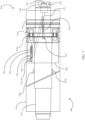
- FIG. 10 an embodiment of an energy generator 1000 is illustrated.
- the energy generator 1000 optionally comprises an inner ring 1040 configured to be supported on (and optionally remain stationary with) shaft 200'.
- the energy generator 1000 optionally comprises an outer ring 1020 configured to be supported in (e.g., press-fit into) and optionally rotate with the cylinder 130.
- protuberances 1022, 1042 or roughness elements or other elements are provided on the inner surface of inner ring 1040 and/or on the outer surface of outer ring 1020, respectively.
- a plurality of radially arranged magnets 1030 are optionally supported in the outer ring 1020.
- a plurality of radially arranged electromagnetic coils 1050 e.g., conductive coils such as copper coils.
- rotation of the outer ring 1020 with the cylinder 130 creates energy which is optionally transmitted to an energy storage device (e.g., battery and/or to a power-consuming component of the system 700).
- energy generation pulses are also transmitted and/or processed by the system 700 to determine a number of rotations and/or a rotational speed of the cylinder 130.
- one or more clamps 1010 are positioned to secure the outer ring 1040 to the cylinder 130.
- One or more rotation sensors are optionally provided to detect a rotational speed and/or number of rotations of the cylinder 130.
- a signal generated by the energy generator 1000 is used to determine the speed and/or number of rotations of cylinder 130 such that the energy generator 1000 may be considered a rotation sensor.
- a different or additional rotation sensor e.g., Hall effect sensor, etc. is provided.
- the rotational speed of the cylinder 130 is compared to a belt speed (e.g., measured or assumed belt speed) in order to estimate a current cylinder diameter and/or current cylinder wear percentage.
- a belt speed e.g., measured or assumed belt speed
- an adjustment factor based on the comparison between the cylinder rotational speed and belt speed may be applied to a nominal cylinder diameter in order to determine a current cylinder diameter.
- a percentage wear of the cylinder 130 may be determined by dividing the current cylinder diameter by the nominal cylinder diameter. The calculation steps described herein may be performed by a processor connected to the idler or remote from the idler.
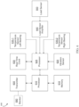
- an idler network monitoring system 900 (which may also be referred to as a conveyor monitoring system) is illustrated schematically.
- a plurality of systems 700 are, via transmitters 605 thereof in data communication with communication gateway 950 such as a LoRaWAN gateway, the specifications of which are provided by the LoRa Alliance of Freemont, California.
- the gateway 950 may be replaced with or supplemented by another communication device such as a WiFi access point.
- the gateway 950 is in data communication (e.g., via an Internet connection) with an application server 960 (e.g., cloud-based application server).
- the application server 960 optionally provides data and/or analysis (e.g., failure analysis, diagnostics, etc.) to a web interface 980, a mobile device 990, and/or to a database 970 (e.g., cloud-based database 970).
- data and/or analysis e.g., failure analysis, diagnostics, etc.
- the application server 960 receives one or more idler-related measurements described herein (i.e. one or more of the measurements carried out by system 700).
- the application server 960 optionally comprises or makes use of an algorithm (e.g., machine learning algorithm, artificial intelligence algorithm, neural network algorithm, deep learning algorithm, JSON interface, etc.) to predict an idler-related diagnostic (e.g., maintenance interval, failure event, failure event time, first component to fail, etc.) based on the idler-related measurements based on measurements .
- the application server identifies an existing idler failure based on one or more idler-related measurements (e.g., temperature, idler rotation speed relative to belt speed or nominal idler rotation speed, shaft load, etc.).
- a registration device 920 (e.g., including a scanner, camera, etc.) is used to register the idler (e.g., by scanning or taking an image of the identifier 810).
- the registration device 920 includes a global positioning (GPS) system or device and optionally identifies the location of each idler upon registration.
- GPS global positioning
- the registration device is optionally in data communication with the system 900 (e.g., via the gateway, web interface, or other component).
- a pulley 1100 is optionally provided with one or more load cells 1200 for measuring loads applied to the pulley.
- the pulley 1100 includes a cylinder 1150 (e.g., metal or other material) having a surface 1125 (e.g., rubber or other material) supported thereon.
- the surface 1125 supports one or more radially outwardly extending lagging elements 1122 (e.g., ceramic, rubber or other material).
- one or more load cells 1200a are disposed on the cylinder 1150 (e.g., beneath the surface 1125).
- one or more load cells 1200b are disposed between the surface 1125 and an optionally modified lagging element 1122'.
- the pulley 1100 includes a wireless transmitter (not shown) in data communication with a load cell associated with said pulley; in some embodiments the wireless sensor associated with the pulley is in data communication with a gateway or other communication device of a conveyor monitoring system such as the system 900.
- Ranges recited herein are intended to inclusively recite all values within the range provided in addition to the maximum and minimum range values. Headings used herein are simply for convenience of the reader and are not intended to be understood as limiting or used for any other purpose.
Landscapes
- Physics & Mathematics (AREA)
- General Physics & Mathematics (AREA)
- Spectroscopy & Molecular Physics (AREA)
- Engineering & Computer Science (AREA)
- Mechanical Engineering (AREA)
- Control Of Conveyors (AREA)
- Arrangements For Transmission Of Measured Signals (AREA)
Claims (8)
- Förderbandüberwachungssystem zum Überwachen einer Vielzahl von Förderbandlaufrollen (100) an einem Förderband, wobei jede Förderbandlaufrolle einen Zylinder (130) mit einer Innenfläche und einer Außenfläche aufweist, der Zylinder durch eine Vielzahl von Lagern (160) rollend auf einer Welle (200) gelagert ist und das Förderbandüberwachungssystem Folgendes umfasst:
eine Vielzahl von Förderbandlaufrollenüberwachungssystemen (600), die jeweils Folgendes umfassen:einen Lagertemperatursensor (635), der angeordnet ist, um die Temperatur von mindestens einem der Lager zu messen;einen Vibrationssensor (725), der dazu konfiguriert ist, Vibration der Förderbandlaufrolle zu detektieren;einen Drahtlossender (605) in Datenkommunikation mit dem Lagertemperatursensor und dem Vibrationssensor, wobei der Drahtlossender dazu konfiguriert ist, Daten von dem Lagertemperatursensor und dem Vibrationssensor an einen Drahtlosempfänger zu übertragen; undeinen Energiegenerator (1000) in elektrischer Verbindung mit dem Drahtlossender, wobei der Energiegenerator durch Drehung des Zylinders relativ zu der Welle angetrieben wird;ein Gateway (950) in Drahtlosdatenkommunikation mit dem Drahtlossender jedes Förderbandlaufrollenüberwachungssystems; dadurch gekennzeichnet, dass das Förderbandüberwachungssystem einen Anwendungsserver (960) in Datenkommunikation mit dem Gateway umfasst, der Anwendungsserver dazu konfiguriert ist, basierend auf Vibrations- und Lagertemperaturdaten, die durch jedes der Förderbandlaufrollenüberwachungssysteme gesammelt werden, einen Laufrollenfehlerzeitpunkt für jede der Förderbandlaufrollen vorherzusagen. - Förderbandüberwachungssystem nach Anspruch 1, wobei jede Förderbandlaufrolle eine eindeutige Kennung (810) beinhaltet, ferner umfassend:
eine Registrierungseinrichtung (920), die eines von einem Scanner oder einer Kamera aufweist, der/die dazu konfiguriert ist, die eindeutige Kennung zu identifizieren und einen Standort einer zugehörigen Förderbandlaufrolle zu speichern, wobei die Registrierungseinrichtung in Datenkommunikation mit einem von dem Gateway und dem Anwendungsserver steht. - Förderbandüberwachungssystem nach Anspruch 1, wobei das Gateway ein LoRaWAN-Gateway umfasst.
- Förderbandüberwachungssystem nach Anspruch 1, ferner umfassend ein Treibrollenüberwachungssystem, das einen Treibrollenlastsensor, der auf einer Treibrolle (1100) gelagert ist, und einen Drahtlossender in Datenkommunikation mit dem Lastsensor und dem Gateway umfasst.
- Förderbandüberwachungssystem nach Anspruch 1, wobei(i) der Anwendungsserver einen cloudbasierten Anwendungsserver umfasst; oder(ii) der Anwendungsserver dazu konfiguriert ist, einen Maschinenlernalgorithmus zu verwenden, um einen Laufrollenfehler vorherzusagen.
- Förderbandüberwachungssystem nach Anspruch 1, wobei(i) der Anwendungsserver in Datenkommunikation mit einer Benutzerschnittstelle steht, die Benutzerschnittstelle eines von einer Webschnittstelle (980) oder einer mobilen Anwendung (990) umfasst, wobei der Anwendungsserver dazu konfiguriert ist, eine Warnung in Bezug auf einen Laufrollenfehler an die Benutzerschnittstelle zu senden, und wobei(ii) die Warnung optional oder vorzugsweise eines von einer Laufrollenkennzeichnung und einem Laufrollenstandort beinhaltet und wobei die Warnung eines oder mehrere von einem vorhergesagten Laufrollenfehler und einem bestehenden Laufrollenfehler umfasst.
- Förderbandüberwachungssystem nach Anspruch 5 Teil (ii), wobei der Anwendungsserver in Datenkommunikation mit einer Benutzerschnittstelle steht und die Benutzerschnittstelle eines von einer Webschnittstelle oder einer mobilen Anwendung umfasst, wobei der Anwendungsserver dazu konfiguriert ist, eine Warnung in Bezug auf einen Laufrollenfehler an die Benutzerschnittstelle zu senden, und optional oder vorzugsweise wobei die Warnung eines von einer Laufrollenkennzeichnung und einem Laufrollenstandort beinhaltet und wobei die Warnung eines oder mehrere von einem vorhergesagten Laufrollenfehler und einem bestehenden Laufrollenfehler umfasst.
- Förderbandüberwachungssystem nach Anspruch 7, wobei der Anwendungsserver einen Algorithmus mit künstlicher Intelligenz nutzt, um basierend auf die laufrollenbezogenen Messungen, die auf den Vibrations- und Temperaturdaten basieren, einen Laufrollenfehlerzeitpunkt vorherzusagen.
Priority Applications (1)
| Application Number | Priority Date | Filing Date | Title |
|---|---|---|---|
| EP25177564.9A EP4578804A3 (de) | 2017-10-30 | 2018-10-30 | Vorrichtung, systeme und verfahren zur überwachung von förderbandrollen |
Applications Claiming Priority (2)
| Application Number | Priority Date | Filing Date | Title |
|---|---|---|---|
| US201762579026P | 2017-10-30 | 2017-10-30 | |
| PCT/US2018/058302 WO2019089661A1 (en) | 2017-10-30 | 2018-10-30 | Conveyor idler monitoring apparatus, systems, and methods |
Related Child Applications (1)
| Application Number | Title | Priority Date | Filing Date |
|---|---|---|---|
| EP25177564.9A Division EP4578804A3 (de) | 2017-10-30 | 2018-10-30 | Vorrichtung, systeme und verfahren zur überwachung von förderbandrollen |
Publications (4)
| Publication Number | Publication Date |
|---|---|
| EP3704043A1 EP3704043A1 (de) | 2020-09-09 |
| EP3704043A4 EP3704043A4 (de) | 2021-08-18 |
| EP3704043C0 EP3704043C0 (de) | 2025-05-21 |
| EP3704043B1 true EP3704043B1 (de) | 2025-05-21 |
Family
ID=66332317
Family Applications (2)
| Application Number | Title | Priority Date | Filing Date |
|---|---|---|---|
| EP18873288.7A Active EP3704043B1 (de) | 2017-10-30 | 2018-10-30 | Vorrichtung, systeme und verfahren zur überwachung von förderbandrollen |
| EP25177564.9A Pending EP4578804A3 (de) | 2017-10-30 | 2018-10-30 | Vorrichtung, systeme und verfahren zur überwachung von förderbandrollen |
Family Applications After (1)
| Application Number | Title | Priority Date | Filing Date |
|---|---|---|---|
| EP25177564.9A Pending EP4578804A3 (de) | 2017-10-30 | 2018-10-30 | Vorrichtung, systeme und verfahren zur überwachung von förderbandrollen |
Country Status (6)
| Country | Link |
|---|---|
| US (1) | US20200256745A1 (de) |
| EP (2) | EP3704043B1 (de) |
| CN (1) | CN111601760A (de) |
| AU (1) | AU2018360571B2 (de) |
| CA (1) | CA3081229A1 (de) |
| WO (1) | WO2019089661A1 (de) |
Families Citing this family (7)
| Publication number | Priority date | Publication date | Assignee | Title |
|---|---|---|---|---|
| DE102019117319A1 (de) * | 2019-06-27 | 2020-12-31 | Gerd Küpper | Sensorrolle für Förder- und Lagertechnische Einrichtungen zur Beförderung von Stückgut |
| EP4013705A4 (de) * | 2019-08-13 | 2023-11-15 | Minesensor Assets Pty Ltd | Sensoranordnung und überwachungssystem für eine spannrolle in einem bandfördersystem |
| EP3797899A1 (de) * | 2019-09-27 | 2021-03-31 | Primetals Technologies Austria GmbH | Vorrichtung und verfahren zum erkennen von einer bewegung eines körpers in einer industrieanlage |
| EP4169023A4 (de) * | 2020-06-17 | 2024-10-09 | Awe Technologies, LLC | Zerstörung von in der luft schwebenden pathogenen und mikroorganismen auf körnern und getrockneten nahrungsmitteln mittels ultraschall |
| DE102021112177A1 (de) * | 2021-05-10 | 2022-11-10 | Interroll Holding Ag | Förderrolle |
| JP7501547B2 (ja) * | 2021-06-30 | 2024-06-18 | 株式会社デンソー | 設備状態監視システム |
| AU2023367773A1 (en) * | 2022-10-25 | 2025-06-05 | Superior Industries, Inc. | Conveyor idler monitoring systems, methods, and apparatus |
Family Cites Families (14)
| Publication number | Priority date | Publication date | Assignee | Title |
|---|---|---|---|---|
| DE29621357U1 (de) * | 1996-12-10 | 1998-01-15 | Sailer, Josef, 87474 Buchenberg | Überwachungsvorrichtung zum Überwachen des Wärmezustands, insbesondere eines Förderbandes |
| GB2402119A (en) * | 2002-01-14 | 2004-12-01 | Univ Carnegie Mellon | Conveyor belt inspection system and method |
| US20100072813A1 (en) * | 2007-01-16 | 2010-03-25 | Mcrae Brian Donald | Crawler Tracks and Idlers for Crawler Tracks |
| SE536095C2 (sv) * | 2010-10-25 | 2013-05-07 | Eistec Ab | Rulle för en bandtransportör innefattande sensorer för övervakning av rullens kondition |
| AU2014328480A1 (en) * | 2013-09-24 | 2016-04-14 | Vayeron Pty Ltd | An idler, a method for monitoring a plurality of idlers, and a conveyor system |
| AU2015100473A4 (en) * | 2014-08-04 | 2015-05-14 | Ezifix Mining Solutions Pty Ltd | Conveyor roller monitoring apparatus |
| US9371630B1 (en) * | 2014-12-19 | 2016-06-21 | Caterpillar Inc. | Determination of undercarriage idler and roller wear based on final drive speed |
| WO2016115591A1 (en) * | 2015-01-21 | 2016-07-28 | Vayeron Pty Ltd | Improvements in conveyor and components therefor, monitoring methods and communication systems |
| AU2016245324B2 (en) * | 2015-04-10 | 2020-01-02 | Orontide Group Ltd | Conveyor pulley monitoring apparatus |
| ITUB20155386A1 (it) * | 2015-11-09 | 2017-05-09 | Rulmeca Holding S P A | Sistema e metodo di controllo di trasportatori comprendenti rulli |
| US20180248983A1 (en) * | 2016-12-21 | 2018-08-30 | Ncore Communications, Inc. | Methods and apparatus for aggregating network access within a single unified platform for a myriad of devices |
| CN107235288B (zh) * | 2017-06-01 | 2020-03-10 | 昆山国显光电有限公司 | 一种辊式输送装置 |
| WO2019166414A1 (de) * | 2018-03-02 | 2019-09-06 | Voith Patent Gmbh | Bestimmung der energieeffizienz eines gurtförderers |
| DE102018104792B4 (de) * | 2018-03-02 | 2021-04-22 | Voith Patent Gmbh | Bestimmung der Energieeffizienz eines Gurtförderers |
-
2018
- 2018-10-30 CA CA3081229A patent/CA3081229A1/en active Pending
- 2018-10-30 EP EP18873288.7A patent/EP3704043B1/de active Active
- 2018-10-30 CN CN201880075747.XA patent/CN111601760A/zh active Pending
- 2018-10-30 WO PCT/US2018/058302 patent/WO2019089661A1/en not_active Ceased
- 2018-10-30 AU AU2018360571A patent/AU2018360571B2/en active Active
- 2018-10-30 EP EP25177564.9A patent/EP4578804A3/de active Pending
-
2020
- 2020-04-30 US US16/864,119 patent/US20200256745A1/en not_active Abandoned
Also Published As
| Publication number | Publication date |
|---|---|
| WO2019089661A1 (en) | 2019-05-09 |
| AU2018360571B2 (en) | 2023-12-21 |
| CN111601760A (zh) | 2020-08-28 |
| EP3704043C0 (de) | 2025-05-21 |
| EP4578804A2 (de) | 2025-07-02 |
| EP4578804A3 (de) | 2025-10-01 |
| EP3704043A1 (de) | 2020-09-09 |
| BR112020008698A2 (pt) | 2020-10-13 |
| EP3704043A4 (de) | 2021-08-18 |
| AU2018360571A1 (en) | 2020-05-28 |
| US20200256745A1 (en) | 2020-08-13 |
| CA3081229A1 (en) | 2019-05-09 |
Similar Documents
| Publication | Publication Date | Title |
|---|---|---|
| EP3704043B1 (de) | Vorrichtung, systeme und verfahren zur überwachung von förderbandrollen | |
| US11993463B2 (en) | Conveyor idler monitoring apparatus, systems, and methods | |
| AU2011321060C1 (en) | Roller for a belt transporter comprising sensors for monitoring the condition of the roller | |
| AU2017100493A4 (en) | An Idler, a Method for Monitoring a Plurality of Idlers, and a Conveyor System | |
| WO2016019431A1 (en) | Conveyor roller monitoring apparatus, system and method | |
| WO2011104433A1 (en) | Monitoring system for monitoring the condition of planetary gears | |
| AU2025200112A1 (en) | A multisensor contained in a seal of a conveyor belt roller | |
| US20220281690A1 (en) | A sensor assembly and monitoring system for an idler roller in a belt conveyor system | |
| CN107764316A (zh) | 用于监测多个马达的状况的系统 | |
| US7796051B2 (en) | Measuring device activated at inspection rounds for condition monitoring of rotating machinery | |
| WO2024003621A1 (en) | An idler monitoring device | |
| JP2017003555A (ja) | センサユニット、センサ付き軸受及び異常診断システム | |
| BR112020008698B1 (pt) | Sistema de monitoramento do transportador para monitorar uma pluralidade de polias transportadoras | |
| US20210187684A1 (en) | Measuring system for monitoring a spindle | |
| WO2016060006A1 (ja) | 機械部品の状態測定装置 | |
| WO2016199846A1 (ja) | センサユニット、センサ付き軸受及び異常診断システム | |
| Triepels | Design of Intelligent Belt |
Legal Events
| Date | Code | Title | Description |
|---|---|---|---|
| STAA | Information on the status of an ep patent application or granted ep patent |
Free format text: STATUS: THE INTERNATIONAL PUBLICATION HAS BEEN MADE |
|
| PUAI | Public reference made under article 153(3) epc to a published international application that has entered the european phase |
Free format text: ORIGINAL CODE: 0009012 |
|
| STAA | Information on the status of an ep patent application or granted ep patent |
Free format text: STATUS: REQUEST FOR EXAMINATION WAS MADE |
|
| 17P | Request for examination filed |
Effective date: 20200507 |
|
| AK | Designated contracting states |
Kind code of ref document: A1 Designated state(s): AL AT BE BG CH CY CZ DE DK EE ES FI FR GB GR HR HU IE IS IT LI LT LU LV MC MK MT NL NO PL PT RO RS SE SI SK SM TR |
|
| AX | Request for extension of the european patent |
Extension state: BA ME |
|
| DAV | Request for validation of the european patent (deleted) | ||
| DAX | Request for extension of the european patent (deleted) | ||
| A4 | Supplementary search report drawn up and despatched |
Effective date: 20210716 |
|
| RIC1 | Information provided on ipc code assigned before grant |
Ipc: B65G 43/02 20060101AFI20210712BHEP Ipc: B65G 39/00 20060101ALI20210712BHEP |
|
| STAA | Information on the status of an ep patent application or granted ep patent |
Free format text: STATUS: EXAMINATION IS IN PROGRESS |
|
| 17Q | First examination report despatched |
Effective date: 20231024 |
|
| GRAP | Despatch of communication of intention to grant a patent |
Free format text: ORIGINAL CODE: EPIDOSNIGR1 |
|
| STAA | Information on the status of an ep patent application or granted ep patent |
Free format text: STATUS: GRANT OF PATENT IS INTENDED |
|
| INTG | Intention to grant announced |
Effective date: 20250103 |
|
| GRAS | Grant fee paid |
Free format text: ORIGINAL CODE: EPIDOSNIGR3 |
|
| GRAA | (expected) grant |
Free format text: ORIGINAL CODE: 0009210 |
|
| STAA | Information on the status of an ep patent application or granted ep patent |
Free format text: STATUS: THE PATENT HAS BEEN GRANTED |
|
| AK | Designated contracting states |
Kind code of ref document: B1 Designated state(s): AL AT BE BG CH CY CZ DE DK EE ES FI FR GB GR HR HU IE IS IT LI LT LU LV MC MK MT NL NO PL PT RO RS SE SI SK SM TR |
|
| REG | Reference to a national code |
Ref country code: GB Ref legal event code: FG4D |
|
| REG | Reference to a national code |
Ref country code: CH Ref legal event code: EP |
|
| REG | Reference to a national code |
Ref country code: IE Ref legal event code: FG4D |
|
| U01 | Request for unitary effect filed |
Effective date: 20250521 |
|
| U07 | Unitary effect registered |
Designated state(s): AT BE BG DE DK EE FI FR IT LT LU LV MT NL PT RO SE SI Effective date: 20250527 |
|
| PG25 | Lapsed in a contracting state [announced via postgrant information from national office to epo] |
Ref country code: ES Free format text: LAPSE BECAUSE OF FAILURE TO SUBMIT A TRANSLATION OF THE DESCRIPTION OR TO PAY THE FEE WITHIN THE PRESCRIBED TIME-LIMIT Effective date: 20250521 |
|
| PG25 | Lapsed in a contracting state [announced via postgrant information from national office to epo] |
Ref country code: NO Free format text: LAPSE BECAUSE OF FAILURE TO SUBMIT A TRANSLATION OF THE DESCRIPTION OR TO PAY THE FEE WITHIN THE PRESCRIBED TIME-LIMIT Effective date: 20250821 Ref country code: GR Free format text: LAPSE BECAUSE OF FAILURE TO SUBMIT A TRANSLATION OF THE DESCRIPTION OR TO PAY THE FEE WITHIN THE PRESCRIBED TIME-LIMIT Effective date: 20250822 |
|
| PG25 | Lapsed in a contracting state [announced via postgrant information from national office to epo] |
Ref country code: PL Free format text: LAPSE BECAUSE OF FAILURE TO SUBMIT A TRANSLATION OF THE DESCRIPTION OR TO PAY THE FEE WITHIN THE PRESCRIBED TIME-LIMIT Effective date: 20250521 |
|
| PG25 | Lapsed in a contracting state [announced via postgrant information from national office to epo] |
Ref country code: HR Free format text: LAPSE BECAUSE OF FAILURE TO SUBMIT A TRANSLATION OF THE DESCRIPTION OR TO PAY THE FEE WITHIN THE PRESCRIBED TIME-LIMIT Effective date: 20250521 |
|
| PGFP | Annual fee paid to national office [announced via postgrant information from national office to epo] |
Ref country code: SE Payment date: 20250929 Year of fee payment: 8 |
|
| PG25 | Lapsed in a contracting state [announced via postgrant information from national office to epo] |
Ref country code: RS Free format text: LAPSE BECAUSE OF FAILURE TO SUBMIT A TRANSLATION OF THE DESCRIPTION OR TO PAY THE FEE WITHIN THE PRESCRIBED TIME-LIMIT Effective date: 20250821 |
|
| PG25 | Lapsed in a contracting state [announced via postgrant information from national office to epo] |
Ref country code: IS Free format text: LAPSE BECAUSE OF FAILURE TO SUBMIT A TRANSLATION OF THE DESCRIPTION OR TO PAY THE FEE WITHIN THE PRESCRIBED TIME-LIMIT Effective date: 20250921 |