EP3703042A1 - Anzeigemittel mit einer streufolie - Google Patents
Anzeigemittel mit einer streufolie Download PDFInfo
- Publication number
- EP3703042A1 EP3703042A1 EP20159697.0A EP20159697A EP3703042A1 EP 3703042 A1 EP3703042 A1 EP 3703042A1 EP 20159697 A EP20159697 A EP 20159697A EP 3703042 A1 EP3703042 A1 EP 3703042A1
- Authority
- EP
- European Patent Office
- Prior art keywords
- light
- scattering film
- light shaft
- chamber
- exit surface
- Prior art date
- Legal status (The legal status is an assumption and is not a legal conclusion. Google has not performed a legal analysis and makes no representation as to the accuracy of the status listed.)
- Granted
Links
Images

Classifications
-
- G—PHYSICS
- G09—EDUCATION; CRYPTOGRAPHY; DISPLAY; ADVERTISING; SEALS
- G09F—DISPLAYING; ADVERTISING; SIGNS; LABELS OR NAME-PLATES; SEALS
- G09F23/00—Advertising on or in specific articles, e.g. ashtrays, letter-boxes
- G09F23/0058—Advertising on or in specific articles, e.g. ashtrays, letter-boxes on electrical household appliances, e.g. on a dishwasher, a washing machine or a refrigerator
-
- G—PHYSICS
- G09—EDUCATION; CRYPTOGRAPHY; DISPLAY; ADVERTISING; SEALS
- G09F—DISPLAYING; ADVERTISING; SIGNS; LABELS OR NAME-PLATES; SEALS
- G09F13/00—Illuminated signs; Luminous advertising
- G09F13/04—Signs, boards or panels, illuminated from behind the insignia
- G09F13/14—Arrangements of reflectors therein
-
- G—PHYSICS
- G09—EDUCATION; CRYPTOGRAPHY; DISPLAY; ADVERTISING; SEALS
- G09F—DISPLAYING; ADVERTISING; SIGNS; LABELS OR NAME-PLATES; SEALS
- G09F13/00—Illuminated signs; Luminous advertising
- G09F13/20—Illuminated signs; Luminous advertising with luminescent surfaces or parts
- G09F13/22—Illuminated signs; Luminous advertising with luminescent surfaces or parts electroluminescent
- G09F2013/222—Illuminated signs; Luminous advertising with luminescent surfaces or parts electroluminescent with LEDs
Definitions
- the invention relates to a display means for a household appliance, comprising a scattering film for generating diffuse light by means of optical scattering and a light shaft with at least one first entrance surface for irradiating light into a first chamber of the light shaft and a first exit surface for emitting that emerging from the first chamber Light to the scattering film, with at least one second entrance surface for shining light into a second chamber of the light shaft and a second exit surface for radiating the light emerging from the second chamber to the scattering film, and with at least one optically separating the first chamber from the second chamber Chamber side wall.
- the DE 10 2015 201 427 A1 discloses a touch-sensitive illuminable control panel, comprising a substrate, a plurality of touch elements on a surface of the control panel, a sensor layer with a plurality of sensor elements, each sensor element being assigned to a touch element, a lighting device which is set up to at least a part of the touch elements illuminate, as well as a control unit, wherein the touch elements have at least two upper keys and at least two groups of lower keys, with each upper key switching at least one group of lower keys is assigned so that when an upper key is touched, the lower keys that belong to the assigned group are activated.
- the EP 3 280 053 A2 discloses an operating module for a household appliance that has a symbol film with at least one touch-sensitive keypad applied to a fastening surface of a carrier, which fastening surface has a luminous area below the at least one keypad, the at least one keypad each having a metal layer with at least one cutout and the Metal layer is electrically conductively connected to an electrical connection of the symbol film.
- the EP 2 936 684 B1 discloses a household appliance with a capacitive control panel and a method for its production.
- the invention relates in particular to a household appliance with a control device, an at least partially transparent panel and an at least partially transparent control panel with at least a capacitive sensor for selecting a program function of the household appliance by a user of the appliance and a method for producing this household appliance.
- the object of the invention is to improve a display means for a household appliance in such a way that a scattering film of the display means is optimally connected to a light shaft of the display means with regard to mechanical stability and optical separation of at least two adjacent exit surfaces.
- a display means for a household appliance having a scattering film for generating diffuse light by means of optical scattering and a light shaft with at least one first entrance surface for irradiating light into a first chamber of the light shaft and a first exit surface for radiating from the light exiting the first chamber to the diffusion film, with at least one second entrance surface for shining light into a second chamber of the light shaft and a second exit surface for radiating the light emerging from the second chamber to the diffusion film, and with at least one of the first chamber of the second Chamber optically separating chamber side wall, furthermore having at least one connecting element molded onto the scattering film, by means of which the scattering film is connected to the light shaft so as to cover the at least one first exit surface and the at least one second exit surface is.
- the display means can be used, for example, to display information on a control panel relating to the functions of the household appliance.
- the display means can be illuminated by lighting means of the household appliance, for example by illuminating different areas of the display means.
- the display means can, for example, support the control of the household appliance, the household appliance being controlled by means of input means that interact with the display means.
- the household appliance can be a mechanical and / or electrical device that is used in particular in a private household. This includes, for example, kitchen appliances, vacuum cleaners or large appliances such as washing machines, dryers, kitchen stoves, refrigerators or dishwashers, but also other small electrical household appliances.
- the scattering film can be an optical component that is used to scatter light. It can therefore be characteristic of the scattering film that it has, for example, a large number of small scattering centers. This can be achieved solely through a surface roughness of the scatter film and / or through an opaque material. When light rays running essentially parallel to each other strike different points on the scattering film, these light rays are distributed in different directions and thus generate diffuse light. The scattering film can cause the light to be scattered on its surface or in its interior.
- the light shaft can be a light-permeable component that enables light to pass through from an entry surface to an exit surface.
- the entry surface can enable light to be coupled into the light shaft and the exit surface can enable the light to be coupled out of the light shaft.
- the light shaft can have a chamber for light to pass through, but in particular it can also be two or more chambers.
- the respective chambers each have a separate entry surface and a separate exit surface for light.
- the two or more chambers can be optically separated from one another by a chamber side wall or by several chamber side walls.
- the connecting element is used to attach the scattering film to the light shaft.
- the connecting element can, for example, be a one-part element or a multi-part element or it can comprise several elements which are molded onto the diffusion film.
- the diffusion film can be connected to the light shaft by means of the at least one connecting element so as to cover the exit surfaces of the light shaft.
- the diffusion film can cover the one exit surface or the multiple exit surfaces of the light shaft over the entire surface, in particular without gaps. As a result, the scattering film can be securely fastened to the light shaft without the need for gluing, for example.
- the display element can display various items of information on a household appliance in different areas, the information being displayed optically, for example, by illuminating the different areas.
- the different areas can be illuminated by one or more illuminants, for example LEDs of the household appliance, which are arranged, for example, on a circuit board.
- the light from the lighting means can be guided into the light shaft by coupling it into the entry surface and onto the diffusion film by coupling it out of the exit surface.
- the diffusing film can be connected to the light shaft by means of the at least one connecting element resting on the light shaft in order to diffusely scatter the light so that essentially complete, uniform illumination of the area of the display element is made possible.
- the connecting element can enable a more compact connection between the diffusion film and the light shaft or between the diffusion film and the display surface, so that, for example, no intermediate holding elements interfere with the arrangement in relation to the display surface or the light shaft, in particular no undesired intermediate light gaps are caused.
- the connecting element can be designed in such a way that the scattering film and the display means are arranged at a minimal distance from one another. This is achieved, in particular, in that no holding elements encompass the scattering film where, like the scattering film, it is intended to be as touching as possible on a rear side of the display means.
- the scattering film with the molded-on connecting element can also simplify automated assembly in that the scattering film and the connecting element are molded onto one another before the scattering film is mounted on the light shaft.
- the shaping of the connecting element onto the scattering film can in particular prevent accidental or undesired detachment of the connecting element from the scattering film.
- the at least one connecting element can be designed as a frame element which surrounds the first exit surface and / or the second exit surface.
- the frame element is used or the frame elements are used to mechanically connect the scattering film to the light shaft.
- the frame element or the frame elements can surround the respective inner edges of the exit surface or of the plurality of exit surfaces, in particular light-tight seal when the frame element or the frame elements are connected to the light shaft or the exit surfaces of the light shaft.
- Each frame element can, for example, surround a single exit surface of the light shaft without gaps, i.e. mounting.
- a single frame element can jointly surround two or more exit surfaces of the light shaft without gaps, i.e. mounting.
- each frame element not only forms a connecting means for mechanically connecting the scattering film to the light shaft, but at the same time also an optical seal, around the respective exit surface of the light shaft, i.e. without any gaps. to be coupled opaque to the scattering film.
- the light from one chamber of the light shaft can be outshone into an adjacent chamber of the light shaft i.e. outshining of the light from a display surface of the diffusion film into an adjacent display surface of the diffusion film can be prevented.
- the at least one connecting element can be molded onto the scattering film by injection molding in an in-mold labeling process.
- An in-mold labeling process can generally be understood as the insertion of substrates such as fabric, paper, wood veneer or any printed or structured foils or other elements, as well as other plastic elements, into an injection molding tool together with a subsequent back injection of these elements with injection plastic .
- the in-mold labeling process enables an injection molding, here the connecting elements according to the invention or the frame elements, to a substrate, here the scattering film, the substrate being produced outside the injection molding tool before the injection molding is molded.
- the substrate, here the scattering film can have been produced by film calendering and is then placed in the open injection molding tool before the injection-molded part, here the connecting elements or the frame elements, are formed by injection molding.
- the at least one connecting element can be molded onto the scattering film by injection molding in an in-mold decoration process.
- An in-mold decoration process can generally be understood to mean the quasi-continuous feeding of substrates such as fabric, paper, wood veneer or any printed or structured foils, here the diffusion foils according to the invention, into an injection molding tool.
- the scatter films are pre-assembled on a carrier tape conveyed through the injection molding tool and when these substrates are subsequently back-molded, i.e. Scatter films with injection-molded plastic bond with the molded part and are detached from the carrier tape when the molded part is ejected and ejected with the molded part.
- the in-mold decoration process enables the molding of an injection-molded part, here the connecting elements or the frame elements on a substrate, here the scattering film, the substrate being produced outside the injection molding tool and pre-assembled on a carrier tape before the injection-molded part is molded.
- the at least one connecting element can have a fastening means for form-fitting connection of the diffusion film to the light shaft, the fastening means being designed as a latching device which has at least one locking projection arranged on the connecting means and at least one locking groove arranged on the light shaft and interacting with the locking projection.
- the at least one connecting element can have a fastening means for form-fitting connection of the diffusion film to the light shaft, the fastening means being designed as a latching which has at least one locking groove arranged on the connecting means and at least one arranged on the light shaft and interacting with the locking groove Has locking projection.
- the latching projection can be, for example, a latching hook which has an inclined contact surface pointing forward in the insertion direction and an undercut arranged behind it, i.e. has a latching step which engages positively in the latching groove in a latched state.
- the latching groove can be designed as a recess or as a recess, the recess or the recess having a cavity which is adapted in shape and size to the latching projection, in particular to the latching hook or to the latching step, so that a latched State of this locking projection or this locking hook can engage positively in the locking groove.
- At each connector or Frame element can be arranged one or more locking projections and locking grooves.
- the latching projection and the latching groove together form the latching and effect a form fit as soon as they are connected to one another.
- the form fit can represent a detachable or non-detachable connection between the scattering film and the light shaft.
- the at least one connecting element can have a fastening means for frictional connection of the diffusion film to the light shaft, the fastening means having at least one displacement rib arranged on the connecting element and at least one clamping groove arranged on the light shaft and cooperating with the displacement rib.
- the at least one connecting element can have a fastening means for frictional connection of the scattering film to the light shaft, the fastening means having at least one clamping groove arranged on the connecting element and at least one displacement rib that interacts with the clamping groove and arranged on the light shaft.
- the displacement rib can be designed, for example, as a bead, a bulge or a rib.
- the displacement rib can in this respect be a thickening in the width of the side wall of the connecting element.
- the displacement ribs preferably extend in the insertion direction.
- the clamping groove can be designed as a recess. In terms of shape and size, the respective clamping groove correlates with the shape and size of the associated displacement rib. In this respect, one or more clamping grooves can be present per connecting element or frame element.
- the clamping grooves extend analogously to the displacement ribs, preferably in the insertion direction.
- the displacement rib and the clamping groove create a force fit as soon as they are pushed into one another.
- the frictional connection can enable a detachable or a non-detachable connection from the scattering film to the light shaft, depending on how high the pressure between the displacement rib and the clamping groove is.
- the diffusion film can have at least one first passage area which is illuminated by the light emerging from the first exit area of the light shaft and at least one second passage area which is irradiated by the light exiting from the second exit area of the light shaft, with between the first passage area and
- the second passage area has a slot for optically separating the first passage area from the second passage area in the diffusion film, in such a way that outshine of light between the first exit area and the second exit area is at least significantly reduced or completely prevented by means of the slot.
- the passage area represents an area of the scattering film through which the light coupled out from the exit area shines through so that it can illuminate an area of the display means.
- the slot can, for example, be a cutout in the scattering film in one or more areas of the scattering film.
- the openings can in particular be arranged between two adjacent passage areas.
- the respective slot can for example be formed by a single elongated opening.
- the slot can reflect and / or refract the light of the first passage area emitted from the one exit area, so that the light from the first passage area is prevented from irradiating into the adjacent other passage area or the adjacent other exit area.
- the light shaft can have a protruding rib extending into the slot for optically separating the light emerging from the first exit surface and the light emerging from the second exit surface, in such a way that an over-radiation between the first passage surface and the second passage surface by means of the projecting rib at least is significantly reduced or completely prevented.
- the protruding rib can be, for example, as a longitudinally extending, dam-shaped elevation in the surface of the light shaft that faces the diffusing film.
- the protruding rib can, for example, reflect, shield and / or refract the light from the exit surface when it is emitted, so that the light emerges from the first passage surface it is prevented from irradiating into the adjacent other passage area or the adjacent other exit area.
- the protruding rib together with the associated slot can increase the optical shielding effect.
- the scattering film can essentially be made of thermoplastic material, in particular polycarbonate.
- thermoplastic material can, for example, be transparent, colorless, opaque and / or colored.
- the diffusion film and the light shaft can essentially have the same material.
- the diffusion film and the light shaft can be made entirely of the same material.
- the object is also achieved by a household appliance having a printed circuit board with at least two lighting means and a display means assigned to the at least two lighting means, as in accordance with one or more of the embodiments described.
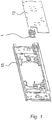
- a control panel 15 of a household appliance for example a stove, is shown viewed from its rear side.
- a display means 1 according to the invention is arranged behind the control panel 15 in the household appliance.
- the display means 1 is assigned to a circuit board 13 of the household appliance.
- the circuit board 13 of the household appliance is an electronic circuit board which has electrical conductor paths and electrical and / or electronic components that are electrically connected by them. These electrical and / or electronic components also include electrical lighting means 14, which can in particular be LEDs. In the case of LEDs in SMD design, the lighting means 14 are soldered directly onto the circuit board 13 and thereby both electrically contacted and mechanically connected to the circuit board 13.
- the display means 1 is assigned to the lighting means 14 of the circuit board 13.
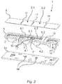
- the display means 1 comprises a scattering film 2 for generating diffuse light by means of optical scattering and a light shaft 3.
- the light shaft 3 has at least a first entry surface 4.1 for irradiating light into a first chamber 5.1 of the light shaft 3 and a first exit surface 6.1 to emit the light emerging from the first chamber 5.1 onto the scattering film 2.
- the light shaft 3 has at least one second entry surface 4.2 for irradiating light into a second chamber 5.2 of the light shaft 3 and a second exit surface 6.2 for radiating the light emerging from the second chamber 5.2 onto the scattering film 2.
- the light shaft 3 also comprises at least one chamber side wall 7 optically separating the first chamber 5.1 from the second chamber 5.2.
- the display means 1 as in particular in FIG Fig. 5 is clearly shown, at least one connecting element 8 molded onto the scattering film 2, by means of which the scattering film 2 is connected to the light shaft 3 the at least one first exit surface 6.1 and the at least one second exit surface 6.2 are connected so as to cover them.
- the invention is representatively described with reference to a first chamber 5.1 and a second chamber 5.2 of the light shaft 3.
- the light shaft 3 can also have three or more such chambers 5.1 and 5.2.
- the light shaft 3 has, for example, exactly four chambers and accordingly also four entry surfaces and four exit surfaces.
- the at least one connecting element 8 is designed as a frame element 8.1 which surrounds the first exit surface 6.1 or the second exit surface 6.2 or another of the other exit surfaces.
- the at least one connecting element 8 has a form-fitting fastening means 9 for the form-fitting connection of the diffusion film 2 to the light shaft 3, the fastening means being designed as a latching mechanism, the at least one latching projection 9.1 arranged on the connection means and at least one on the light shaft 3 with which Has locking projection 9.1 interacting locking groove 9.2.
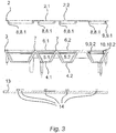
- the at least one connecting element 8 can have a non-positive fastening means 10 for non-positively connecting the diffusion film 2 to the light shaft 3, the fastening means having at least one displacement rib 10.1 arranged on the connecting element 8 and at least one displacement rib 10.1 arranged on the light shaft 3 with the displacement rib 10.1 has cooperating clamping groove 10.2, as shown in particular in Fig. 3 is shown.
- the scattering film 2 has at least one first passage area 2.1 which is illuminated by the light emerging from the first exit area 6.1 of the light shaft 3.
- the scattering film 2 has at least one second passage area 2.2, which is illuminated by the light emerging from the second exit area 6.2 of the light shaft 3.
- a slot 11 for optically separating the first passage area 2.1 from the second passage area 2.2 in the diffusion film 2, so that light outshines between the first exit area 6.1 and the second exit area 6.2 is at least significantly reduced or completely prevented by means of the slot 11.
- the light shaft 3 also comprises a protruding rib 12 extending into the slot 11 for optically separating the light emerging from the first exit surface 6.1 and the light emerging from the second exit surface 6.2, in such a way that overexposure between the first passage surface 2.1 and the second passage area 2.2 by means of the protruding rib 12 is at least significantly reduced or completely prevented.
Landscapes
- Physics & Mathematics (AREA)
- General Physics & Mathematics (AREA)
- Engineering & Computer Science (AREA)
- Theoretical Computer Science (AREA)
- Illuminated Signs And Luminous Advertising (AREA)
- Optical Elements Other Than Lenses (AREA)
Abstract
Description
- Die Erfindung betrifft ein Anzeigemittel für ein Haushaltsgerät, aufweisend eine Streufolie zum Erzeugen von diffusem Licht mittels optischer Streuung und einen Lichtschacht mit wenigstens einer ersten Eintrittsfläche zum Einstrahlen von Licht in eine erste Kammer des Lichtschachtes und einer ersten Austrittsfläche zum Abstrahlen des aus der ersten Kammer austretenden Lichtes an die Streufolie, mit wenigstens einer zweiten Eintrittsfläche zum Einstrahlen von Licht in eine zweite Kammer des Lichtschachtes und einer zweiten Austrittsfläche zum Abstrahlen des aus der zweiten Kammer austretenden Lichtes an die Streufolie, und mit wenigstens einer die erste Kammer von der zweiten Kammer optisch abtrennende Kammerseitenwand.
- Die
DE 10 2015 201 427 A1 offenbart ein berührungsempfindliches beleuchtbares Bedienpanel, umfassend ein Substrat, eine Vielzahl von Berührelementen auf einer Oberfläche des Bedienpanels, eine Sensorschicht mit einer Vielzahl von Sensorelementen, wobei jedes Sensorelement einem Berührelement zugeordnet ist, eine Beleuchtungsvorrichtung, welche eingerichtet ist, um mindestens einen Teil der Berührelemente zu beleuchten, sowie eine Steuereinheit, wobei die Berührelemente mindestens zwei Obertasten und mindestens zwei Gruppen von Untertasten aufweisen, wobei schalttechnisch jeder Obertaste mindestens eine Gruppe von Untertasten derart zugeordnet ist, so dass bei Berührung einer Obertaste die Untertasten aktiviert werden, welche zur zugeordneten Gruppe gehören. - Die
EP 3 280 053 A2 offenbart ein Bedienmodul für ein Haushaltsgerät, dass eine auf einer Befestigungsfläche eines Trägers aufgebrachte Symbolfolie mit mindestens einem berührungsempfindlichen Tastenfeld aufweist, welche Befestigungsfläche unterhalb des mindestens einen Tastfelds einen Leuchtbereich aufweist, wobei das mindestens eine Tastenfeld jeweils eine Metallschicht mit mindestens einer eingebrachten Aussparung aufweist und die Metallschicht elektrisch leitend mit einem elektrischen Anschluss der Symbolfolie verbunden ist. - Die
EP 2 936 684 B1 offenbart ein Haushaltsgerät mit einem kapazitiven Bedienpanel sowie ein Verfahren zu seiner Herstellung. Die Erfindung betrifft insbesondere ein Haushaltsgerät mit einer Steuereinrichtung, einer mindestens teilweise lichtdurchlässigen Blende sowie mit einem mindestens teilweise lichtdurchlässigen Bedienpanel mit mindestens einem kapazitiven Sensor zur Auswahl einer Programmfunktion des Haushaltsgerätes durch einen Benutzer des Gerätes sowie ein Verfahren zur Herstellung dieses Haushaltsgerätes. - Aufgabe der Erfindung ist es, ein Anzeigemittel für ein Haushaltsgerät derart zu verbessern, dass eine Streufolie des Anzeigemittels mit einem Lichtschacht des Anzeigemittels hinsichtlich mechanischer Stabilität und optischer Trennung wenigstens zwei benachbarter Austrittsflächen optimal zu verbinden ist.
- Die Aufgabe wird erfindungsgemäß gelöst durch ein Anzeigemittel für ein Haushaltsgerät, aufweisend eine Streufolie zum Erzeugen von diffusem Licht mittels optischer Streuung und einen Lichtschacht mit wenigstens einer ersten Eintrittsfläche zum Einstrahlen von Licht in eine erste Kammer des Lichtschachtes und einer ersten Austrittsfläche zum Abstrahlen des aus der ersten Kammer austretenden Lichtes an die Streufolie, mit wenigstens einer zweiten Eintrittsfläche zum Einstrahlen von Licht in eine zweite Kammer des Lichtschachtes und einer zweiten Austrittsfläche zum Abstrahlen des aus der zweiten Kammer austretenden Lichtes an die Streufolie, und mit wenigstens einer die erste Kammer von der zweiten Kammer optisch abtrennende Kammerseitenwand, des Weiteren aufweisend wenigstens ein an die Streufolie angeformtes Verbindungselement, mittels dem die Streufolie mit dem Lichtschacht die wenigstens eine erste Austrittsfläche und die wenigstens eine zweite Austrittsfläche überdeckend verbunden ist.
- Das Anzeigemittel kann beispielsweise zum Darstellen von Informationen an einer Bedienblende zu den Funktionen des Haushaltsgerätes verwendet werden. Dazu kann das Anzeigemittel durch Leuchtmittel des Haushaltsgerätes angestrahlt werden, beispielsweise durch Anleuchten unterschiedlicher Bereiche des Anzeigemittels. Weiterhin kann das Anzeigemittel beispielsweise das Steuern des Haushaltsgerätes unterstützen, wobei das Haushaltsgerät mittels Eingabemittel, die mit dem Anzeigemittel zusammenwirken, gesteuert wird.
- Das Haushaltsgerät kann ein mechanisches und/oder elektrisches Gerät sein, das insbesondere in einem Privathaushalt benutzt wird. Darunter fallen beispielsweise Küchengeräte, Staubsauger oder Großgeräte wie Waschmaschinen, Trockner, Küchenherde, Kältegeräte oder Geschirrspülmaschinen, aber auch sonstige elektrische Haushaltskleingeräte.
- Die Streufolie kann ein optisches Bauteil sein, das dazu eingesetzt wird, Licht zu streuen. Charakteristisch für die Streufolie kann daher sein, dass sie beispielsweise eine große Anzahl kleiner Streuzentren aufweist. Dies kann allein durch eine Oberflächenrauhigkeit der Streufolie und/oder durch einen opaken Werkstoff erreicht werden. Beim Auftreffen von im Wesentlichen parallel laufenden Lichtstrahlen an verschiedene Stellen der Streufolie, werden diese Lichtstrahlen in unterschiedliche Richtung verteilt und erzeugen so diffuses Licht. Die Streufolie kann die Streuung des Lichts an ihrer Oberfläche oder in ihrem Inneren bewirken.
- Der Lichtschacht kann ein lichtdurchlässiges Bauteil sein, das ein Hindurchstrahlen von Licht von einer Eintrittsfläche zu einer Austrittsfläche ermöglicht. Die Eintrittsfläche kann das Einkoppeln von Licht in den Lichtschacht ermöglichen und die Austrittsfläche kann das Auskoppeln des Lichtes aus dem Lichtschacht ermöglichen. Beispielsweise kann der Lichtschacht eine Kammer zum Hindurchstrahlen von Licht aufweisen, insbesondere können es aber auch zwei oder mehr Kammern sein. Die jeweiligen Kammern weisen eine jeweils separate Eintrittsfläche und eine jeweils separate Austrittsfläche für Licht auf. Die zwei oder mehreren Kammern können durch eine Kammerseitenwand oder durch mehrere Kammerseitenwände voneinander optisch abgetrennt sein.
- Das Verbindungselement dient zum Befestigen der Streufolie an dem Lichtschacht. Das Verbindungselement kann beispielsweise ein einteiliges Element oder ein mehrteiliges Element sein bzw. es kann mehrere Elemente umfassen, die an die Streufolie angeformt sind.
- Die Streufolie kann mittels des wenigstens einen Verbindungselementes die Austrittsflächen des Lichtschachts überdeckend mit dem Lichtschacht verbunden werden. Die Streufolie kann die eine Austrittsfläche oder die mehreren Austrittsflächen des Lichtschachtes ganzflächig, insbesondere spaltfrei überdecken. Dadurch kann eine sichere Befestigung der Streufolie an dem Lichtschacht erzielt werden, ohne dass beispielsweise ein Kleben erforderlich wäre.
- Das Anzeigeelement kann in unterschiedlichen Bereichen verschiedene Informationen eines Haushaltsgerätes anzeigen, wobei die Informationen bspw. durch Beleuchten der unterschiedlichen Bereiche optisch dargestellt werden. Das Beleuchten der unterschiedlichen Bereiche kann dabei durch ein oder mehrere Leuchtmittel, wie beispielsweise LEDs, des Haushaltsgerätes erfolgen, die beispielsweise auf einer Leiterplatte angeordnet sind. Das Licht der Leuchtmittel kann durch Einkoppeln in die Eintrittsfläche in den Lichtschacht hinein und durch Auskoppeln aus der Austrittsfläche zu der Streufolie hingeführt werden. Die Streufolie kann mittels des wenigstens einen Verbindungselementes aufliegend auf dem Lichtschacht mit dem Lichtschacht verbunden werden, um das Licht diffus zu streuen, sodass im Wesentlichen ein vollständiges, gleichmäßiges Beleuchten des Bereiches des Anzeigeelementes ermöglichen wird.
- Das Verbindungselement kann eine kompaktere Verbindung zwischen Streufolie und Lichtschacht bzw. zwischen Streufolie und Anzeigefläche ermöglichen, so dass beispielsweise keine dazwischenliegenden Halteelemente die Anordnung im Bezug zur Anzeigefläche oder zum Lichtschacht stören, insbesondere keine unerwünschten Zwischenlichtspalte verursacht werden.
- Das Verbindungselement kann derart ausgebildet sein, das die Streufolie und das Anzeigemittel in einem minimalen Abstand zueinander angeordnet sind. Dies wird insbesondere dadurch erreicht, dass keine Halteelemente die Streufolie dort umgreifen, wo wie Streufolie möglichst berührend an einer Rückseite des Anzeigemittels anliegen soll.
- Die Streufolie mit dem angeformten Verbindungselement kann außerdem eine automatisierte Montage vereinfachen, indem die Streufolie und das Verbindungselement aneinander angeformt sind, bevor eine Montage der Streufolie an dem Lichtschacht erfolgt.
- Das Anformen des Verbindungselementes an die Streufolie kann insbesondere ein zufälliges bzw. unerwünschtes Ablösen des Verbindungselementes von der Streufolie verhindern.
- Das wenigstens eine Verbindungselement kann als ein Rahmenelement ausgebildet sein, das die erste Austrittsfläche und/oder die zweite Austrittsfläche umgibt. Das Rahmenelement dient oder die Rahmenelemente dienen zur mechanischen Verbindung der Streufolie mit dem Lichtschacht.
- Das Rahmenelement kann oder die Rahmenelemente können die jeweiligen Innenränder der Austrittsfläche oder der mehreren Austrittsflächen einfassten, insbesondere lichtdicht abdichten, wenn das Rahmenelement oder die Rahmenelemente mit dem Lichtschacht bzw. den Austrittsflächen des Lichtschachts verbunden sind.
- Jedes Rahmenelement kann beispielsweise jeweils eine einzelne Austrittsfläche des Lichtschachts spaltfrei umgeben d.h. einfassen. Alternativ kann gegebenenfalls ein einzelnes Rahmenelement zwei oder mehrere Austrittsflächen des Lichtschachts gemeinsam spaltfrei umgeben d.h. einfassen. Jedes Rahmenelement bildet insoweit nicht nur ein Verbindungsmittel zum mechanischen Verbinden der Streufolie mit dem Lichtschacht, sondern gleichzeitig auch eine optische Dichtung, um die jeweilige Austrittsfläche des Lichtschachtes optisch spaltfrei d.h. lichtundurchlässig an die Streufolie anzukoppeln. Insbesondere kann dadurch ein Überstrahlen des Lichtes aus einer Kammer des Lichtschachtes in eine benachbarte Kammer des Lichtschachtes d.h. ein Überstrahlen des Lichtes von einer Anzeigefläche der Streufolie in eine benachbarte Anzeigefläche der Streufolie verhindert werden.
- Das wenigstens eine Verbindungselement kann durch Spritzgießen in einem In-Mould-Labeling-Verfahren an der Streufolie angeformt sein.
- Unter einem In-Mould-Labeling-Verfahren kann im Allgemeinen das Einlegen von Substraten wie Stoff, Papier, Holzfurnier oder beliebig bedruckte oder strukturierte Folien oder sonstiger Elemente, wie auch anderer Kunststoffelemente in ein Spritzgießwerkzeug zusammen mit einem anschließenden Hinterspritzen dieser Elemente mit Spritzkunststoff verstanden werden.
- Das In-Mould-Labeling-Verfahren ermöglicht das Anformen eines Spritzlings, hier die erfindungsgemäßen Verbindungselemente bzw. die Rahmenelemente an ein Substrat, hier die Streufolie, wobei das Substrat vor einem Anformen des Spritzlings außerhalb des Spritzgießwerkzeug hergestellt worden ist. Beispielsweise kann das Substrat, hier die Streufolie, durch Folienkalandrieren hergestellt worden sein und wird dann in das geöffnete Spritzgießwerkzeug eingelegt, bevor der Spritzling, hier die Verbindungselemente bzw. die Rahmenelemente durch Spritzgießen angeformt werden.
- Das wenigstens eine Verbindungselement kann durch Spritzgießen in einem In-Mould-Decoration-Verfahren an der Streufolie angeformt sein.
- Unter einem In-Mould-Decoration-Verfahren kann im Allgemeinen das quasikontinuierliche Hineinfördern von Substraten wie Stoff, Papier, Holzfurnier oder beliebig bedruckte oder strukturierte Folien, hier die erfindungsgemäßen Streufolien, in ein Spritzgießwerkzeug verstanden werden, wobei die Substrate d.h. die Streufolien auf einem durch das Spritzgießwerkzeug hindurchgefördertem Trägerband vorkonfektioniert sind und beim anschließenden Hinterspritzen dieser Substrate d.h. Streufolien mit Spritzkunststoff sich mit dem Spritzling verbinden und beim Auswerfen des Spritzlings von dem Trägerband abgelöst und mit dem Spritzling ausgeworfen werden.
- Das In-Mould-Decoration-Verfahren ermöglicht das Anformen eines Spritzlings, hier die Verbindungselemente bzw. die Rahmenelemente an ein Substrat, hier die Streufolie, wobei das Substrat vor einem Anformen des Spritzlings außerhalb des Spritzgießwerkzeug hergestellt und auf einem Trägerband vorkonfektioniert worden ist.
- Das wenigstens eine Verbindungselement kann ein Befestigungsmittel zum formschlüssigen Verbinden der Streufolie mit dem Lichtschacht aufweisen, wobei das Befestigungsmittel als eine Verrastung ausgebildet ist, die wenigstens einen am Verbindungsmittel angeordneten Rastvorsprung und wenigstens eine an dem Lichtschacht angeordnete, mit dem Rastvorsprung zusammenwirkende Rastnut aufweist. In einer konstruktiv umgekehrten Variante kann das wenigstens eine Verbindungselement ein Befestigungsmittel zum formschlüssigen Verbinden der Streufolie mit dem Lichtschacht aufweisen, wobei das Befestigungsmittel als eine Verrastung ausgebildet ist, die wenigstens eine am Verbindungsmittel angeordnete Rastnut und wenigstens einen an dem Lichtschacht angeordneten, mit der Rastnut zusammenwirkenden Rastvorsprung aufweist.
- Der Rastvorsprung kann beispielsweise ein Rasthaken sein, der eine in Steckrichtung nach vorne weisende Anlaufschrägfläche und eine dahinter angeordnete Hinterschneidung d.h. eine Raststufe aufweist, die in einem verrasteten Zustand in die Rastnut formschlüssig eingreift.
- Die Rastnut kann als eine Aussparung oder als ein Rücksprung ausgebildet sein, wobei die Aussparung bzw. der Rücksprung einen Hohlraum aufweist, der in Gestalt und Größe an den Rastvorsprung, insbesondere an den Rasthaken bzw. an die Raststufe angepasst ist, so dass in einem verrasteten Zustand dieser Rastvorsprung bzw. dieser Rasthaken in die Rastnut formschlüssig eingreifen kann. An jedem Verbindungselement oder Rahmenelement können eine oder mehrere Rastvorsprünge und Rastnuten angeordnet sein.
- Der Rastvorsprung und die Rastnut bilden zusammen die Verrastung und bewirken einen Formschluss, sobald sie miteinander verbunden sind. Der Formschluss kann eine lösbare oder nicht lösbare Verbindung der Streufolie mit dem Lichtschacht darstellen.
- Das wenigstens eine Verbindungselement kann ein Befestigungsmittel zum kraftschlüssigen Verbinden der Streufolie mit dem Lichtschacht aufweisen, wobei das Befestigungsmittel wenigstens eine an dem Verbindungselement angeordnete Verdrängungsrippe und wenigstens eine an dem Lichtschacht angeordnete, mit der Verdrängungsrippe zusammenwirkende Klemmnut aufweist. In einer konstruktiv umgekehrten Variante kann das wenigstens eine Verbindungselement ein Befestigungsmittel zum kraftschlüssigen Verbinden der Streufolie mit dem Lichtschacht aufweisen, wobei das Befestigungsmittel wenigstens eine an dem Verbindungselement angeordnete Klemmnut und wenigstens eine an dem Lichtschacht angeordnete, mit der Klemmnut zusammenwirkende Verdrängungsrippe aufweist.
- Die Verdrängungsrippe kann bspw. als eine Wulst, eine Bauchung oder eine Rippe ausgebildet sein. Die Verdrängungsrippe kann insoweit eine Verdickung in der Seitenwandbreite des Verbindungselements sein. Es können ein oder mehrere Verdrängungsrippen je Verbindungselement oder Rahmenelement vorhanden sein. Die Verdrängungsrippen erstrecken sich vorzugsweise in Steckrichtung.
- Die Klemmnut kann als eine Aussparung ausgebildet sein. Hinsichtlich Form und Größe korreliert die jeweilige Klemmnut mit der Form und Größe der zugeordneten Verdrängungsrippe. Es können insoweit ein oder mehrere Klemmnuten je Verbindungselement oder Rahmenelement vorhanden sein. Die Klemmnuten erstrecken sich analog den Verdrängungsrippen vorzugsweise in Steckrichtung.
- Die Verdrängungsrippe und die Klemmnut bewirken einen Kraftschluss, sobald sie ineinandergeschoben sind. Der Kraftschluss kann eine lösbare oder eine nicht lösbare Verbindung von der Streufolie zu dem Lichtschacht ermöglichen, je nachdem, wie hoch die Pressung zwischen Verdrängungsrippe und Klemmnut ist.
- Die Streufolie kann wenigstens eine erste Durchtrittsfläche aufweisen, die von dem aus der ersten Austrittsfläche des Lichtschachtes austretenden Licht angestrahlt ist und dabei wenigstens eine zweite Durchtrittsfläche aufweisen, die von dem aus der zweiten Austrittsfläche des Lichtschachtes austretenden Licht angestrahlt ist, wobei zwischen der ersten Durchtrittsfläche und der zweiten Durchtrittsfläche sich ein Schlitz zum optischen Trennen der ersten Durchtrittsfläche von der zweiten Durchtrittsfläche in der Streufolie erstreckt, derart, dass ein Überstrahlen von Licht zwischen der ersten Austrittsfläche und der zweiten Austrittsfläche mittels des Schlitzes zumindest deutlich verringert oder ganz verhindert ist.
- Die Durchtrittsfläche stellt einen Bereich der Streufolie dar, durch den das aus der Austrittfläche ausgekoppelte Licht durchstrahlt, sodass es einen Bereich des Anzeigemittels beleuchten kann.
- Der Schlitz kann beispielsweise eine Aussparung in der Streufolie an einem oder mehreren Bereichen der Streufolie sein. Die Öffnungen können insbesondere zwischen jeweils zwei benachbarten Durchtrittsflächen angeordnet sein. Der jeweilige Schlitz kann beispielsweise von einer einzelnen länglichen Öffnung gebildet werden.
- Der Schlitz kann das aus der einen Austrittsfläche abgestrahlte Licht der ersten Durchtrittsfläche reflektieren und/oder brechen, sodass das Licht aus der ersten Durchtrittsfläche daran gehindert wird in die benachbarte andere Durchtrittsfläche bzw. die benachbarte andere Austrittsfläche anzustrahlen.
- Der Lichtschacht kann eine vorspringende, sich in den Schlitz erstreckende Rippe zum optischen Trennen des aus der ersten Austrittsfläche austretenden Lichtes und des aus der zweiten Austrittsfläche austretenden Lichts aufweisen, derart, dass ein Überstrahlen zwischen der ersten Durchtrittsfläche und der zweiten Durchtrittsfläche mittels der vorspringenden Rippe zumindest deutlich verringert oder ganz verhindert ist.
- Die vorspringende Rippe kann bspw. als eine sich längserstreckende, dammförmige Erhebung in der Oberfläche des Lichtschachtes, die der Streufolie zugewandt ist, sein.
- Die vorspringende Rippe kann bspw. das Licht der Austrittsfläche beim Abstrahlen reflektieren, abschirmen und/oder brechen, sodass das Licht aus der ersten Durchtrittsfläche daran gehindert wird in die benachbarte andere Durchtrittsfläche bzw. die benachbarte andere Austrittsfläche anzustrahlen.
- Die vorspringende Rippe kann zusammen mit dem zugeordneten Schlitz die optische Abschirmwirkung vergrößern.
- Die Streufolie kann im Wesentlichen aus thermoplastischen Werkstoff, insbesondere Polycarbonat hergestellt sein.
- Der thermoplastische Werkstoff kann bspw. transparent, farblos, opak und/oder eingefärbt sein.
- Die Streufolie und der Lichtschacht können im Wesentlichen den gleichen Werkstoff aufweisen.
- Beispielsweise können die Streufolie und der Lichtschacht vollständig aus dem gleichen Werkstoff hergestellt sein.
- Die Aufgabe wird außerdem gelöst durch ein Haushaltsgerät aufweisend eine Leiterplatte mit wenigstens zwei Leuchtmitteln und einem den wenigstens zwei Leuchtmitteln zugeordneten Anzeigemittel, wie nach einer oder mehreren der beschriebenen Ausführungen.
- Es zeigen:
- FIG. 1
- eine Explosionsdarstellung der Baugruppe einer Bedienblende eines Haushaltsgeräts, mit mehreren Anzeigemitteln, sowie einer Leiterplatte mit mehreren Leuchtmitteln und Lichtschächten mit Streufolien,
- FIG. 2
- eine Explosionsdarstellung der Baugruppe mit einer Leiterplatte mit mehreren Leuchtmitteln, eines beispielhaften Lichtschachtes und einer Streufolie,
- FIG. 3
- eine Schnittdarstellung der Baugruppe gemäß
Fig. 2 mit der Leiterplatte mit mehreren Leuchtmitteln, dem beispielhaften Lichtschachtes und der Streufolie, - FIG. 4
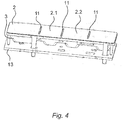
- eine perspektivische Darstellung der Baugruppe gemäß
Fig. 2 undFig. 3 mit der Leiterplatte mit mehreren Leuchtmitteln, dem beispielhaften Lichtschachtes und der Streufolie, im Zusammenbau, - FIG. 5
- eine perspektivische Darstellung der Streufolie in Alleinstellung mit den angeformten Rahmenelementen und Schlitzen.
- In der
Fig. 1 ist eine Bedienblende 15 eines Haushaltsgeräts, beispielsweise eines Herdes von seiner Rückseite aus betrachtet dargestellt. Hinter der Bedienblende 15 ist im Haushaltsgerät ein Anzeigemittel 1 gemäß der Erfindung angeordnet. Das Anzeigemittel 1 ist einer Leiterplatte 13 des Haushaltsgeräts zugeordnet. Die Leiterplatte 13 des Haushaltsgeräts ist eine elektronische Leiterplatte, die elektrische Leitungsbahnen und durch diese elektrisch verbundene elektrische und/oder elektronische Bauteile aufweist. Diese elektrischen und/oder elektronischen Bauteile umfassen auch elektrische Leuchtmittel 14, die insbesondere LEDs sein können. Im Falle von LEDs in SMD-Bauweise sind die Leuchtmittel 14 direkt auf der Leiterplatte 13 aufgelötet und dadurch sowohl elektrisch kontaktiert, als auch mechanisch mit der Leiterplatte 13 verbunden. Das Anzeigemittel 1 ist den Leuchtmitteln 14 der Leiterplatte 13 zugeordnet. - Wie in den folgenden
Figuren 2 bis 5 dargestellt ist, umfasst das erfindungsgemäße Anzeigemittel 1 eine Streufolie 2 zum Erzeugen von diffusem Licht mittels optischer Streuung und einen Lichtschacht 3. Der Lichtschacht 3 weist wenigstens eine erste Eintrittsfläche 4.1 zum Einstrahlen von Licht in eine erste Kammer 5.1 des Lichtschachtes 3 und eine erste Austrittsfläche 6.1 zum Abstrahlen des aus der ersten Kammer 5.1 austretenden Lichtes an die Streufolie 2 auf. Des Weiteren weist der Lichtschacht 3 wenigstens eine zweite Eintrittsfläche 4.2 zum Einstrahlen von Licht in eine zweite Kammer 5.2 des Lichtschachtes 3 und eine zweite Austrittsfläche 6.2 zum Abstrahlen des aus der zweiten Kammer 5.2 austretenden Lichtes an die Streufolie 2 auf. Der Lichtschacht 3 umfasst außerdem wenigstens eine die erste Kammer 5.1 von der zweiten Kammer 5.2 optisch abtrennende Kammerseitenwand 7 auf. Erfindungsgemäß weist das Anzeigemittel 1, wie insbesondere inFig. 5 deutlich herausgestellt ist, wenigstens ein an die Streufolie 2 angeformtes Verbindungselement 8 auf, mittels dem die Streufolie 2 mit dem Lichtschacht 3 die wenigstens eine erste Austrittsfläche 6.1 und die wenigstens eine zweite Austrittsfläche 6.2 überdeckend verbunden ist. - Die Erfindung ist repräsentativ anhand einer ersten Kammer 5.1 und einer zweiten Kammer 5.2 des Lichtschachtes 3 beschrieben. Jedoch kann der Lichtschacht 3 auch drei oder mehrere solcher Kammer 5.1 und 5.2 aufweisen. Im dargestellten Ausführungsbeispiel der
Fig. 2 bis Fig. 2 weist der Lichtschacht 3 beispielsweise genau vier Kammern und demgemäß auch vier Eintrittsflächen und vier Austrittsflächen auf. - Das wenigstens eine Verbindungselement 8 ist als ein Rahmenelement 8.1 ausgebildet, das die erste Austrittsfläche 6.1 bzw. die zweite Austrittsfläche 6.2 oder eine weitere der anderen Austrittsflächen umgibt.
- Das wenigstens eine Verbindungselement 8 weist ein formschlüssiges Befestigungsmittel 9 zum formschlüssigen Verbinden der Streufolie 2 mit dem Lichtschacht 3 auf, wobei das Befestigungsmittel als eine Verrastung ausgebildet ist, die wenigstens einen am Verbindungsmittel angeordneten Rastvorsprung 9.1 und wenigstens eine an dem Lichtschacht 3 angeordnete, mit dem Rastvorsprung 9.1 zusammenwirkende Rastnut 9.2 aufweist.
- Alternativ oder ergänzend kann das wenigstens eine Verbindungselement 8 ein kraftschlüssiges Befestigungsmittel 10 zum kraftschlüssigen Verbinden der Streufolie 2 mit dem Lichtschacht 3 aufweisen, wobei das Befestigungsmittel wenigstens eine an dem Verbindungselement 8 angeordnete Verdrängungsrippe 10.1 und wenigstens eine an dem Lichtschacht 3 angeordnete, mit der Verdrängungsrippe 10.1 zusammenwirkende Klemmnut 10.2 aufweist, wie dies insbesondere in
Fig. 3 aufgezeigt ist. - Die Streufolie 2 weist wenigstens eine erste Durchtrittsfläche 2.1 auf, die von dem aus der ersten Austrittsfläche 6.1 des Lichtschachtes 3 austretenden Licht angestrahlt ist. Außerdem weist die Streufolie 2 wenigstens eine zweite Durchtrittsfläche 2.2 auf, die von dem aus der zweiten Austrittsfläche 6.2 des Lichtschachtes 3 austretenden Licht angestrahlt ist. Beispielsweise zwischen der ersten Durchtrittsfläche 2.1 und der zweiten Durchtrittsfläche 2.2 erstreckt sich ein Schlitz 11 zum optischen Trennen der ersten Durchtrittsfläche 2.1 von der zweiten Durchtrittsfläche 2.2 in der Streufolie 2, derart, dass ein Überstrahlen von Licht zwischen der ersten Austrittsfläche 6.1 und der zweiten Austrittsfläche 6.2 mittels des Schlitzes 11 zumindest deutlich verringert oder ganz verhindert ist.
- Der Lichtschacht 3 umfasst darüber hinaus eine vorspringende, sich in den Schlitz 11 erstreckende Rippe 12 zum optischen Trennen des aus der ersten Austrittsfläche 6.1 austretenden Lichtes und des aus der zweiten Austrittsfläche 6.2 austretenden Lichts, derart, dass ein Überstrahlen zwischen der ersten Durchtrittsfläche 2.1 und der zweiten Durchtrittsfläche 2.2 mittels der vorspringenden Rippe 12 zumindest deutlich verringert oder ganz verhindert ist.
-
- 1
- Anzeigemittel
- 2
- Streufolie
- 2.1
- Erste Durchtrittsfläche
- 2.2
- Zweite Durchtrittsfläche
- 3
- Lichtschacht
- 4.1
- Erste Eintrittsfläche
- 4.2
- Zweite Eintrittsfläche
- 5.1
- Erste Kammer
- 5.2
- Zweite Kammer
- 6.1
- Erste Austrittsfläche
- 6.2
- Zweite Austrittsfläche
- 7
- Kammerseitenwand
- 8
- Verbindungselement
- 8.1
- Rahmenelement
- 9
- formschlüssiges Befestigungsmittel
- 9.1
- Rastvorsprung
- 9.2
- Rastnut
- 10
- kraftschlüssiges Befestigungsmittel
- 10.1
- Verdrängungsrippe
- 10.2
- Klemmnut
- 11
- Schlitz
- 12
- vorspringende Rippe
- 13
- Leiterplatte
- 14
- Leuchtmittel
- 15
- Bedienblende
Claims (11)
- Anzeigemittel für ein Haushaltsgerät, aufweisend eine Streufolie (2) zum Erzeugen von diffusem Licht mittels optischer Streuung und einen Lichtschacht (3) mit wenigstens einer ersten Eintrittsfläche (4.1) zum Einstrahlen von Licht in eine erste Kammer (5.1) des Lichtschachtes (3) und einer ersten Austrittsfläche (6.1) zum Abstrahlen des aus der ersten Kammer (5.1) austretenden Lichtes an die Streufolie (2), mit wenigstens einer zweiten Eintrittsfläche (4.2) zum Einstrahlen von Licht in eine zweite Kammer (5.2) des Lichtschachtes (3) und einer zweiten Austrittsfläche (6.2) zum Abstrahlen des aus der zweiten Kammer (5.2) austretenden Lichtes an die Streufolie (2), und mit wenigstens einer die erste Kammer (5.1) von der zweiten Kammer (5.2) optisch abtrennende Kammerseitenwand (7), gekennzeichnet durch wenigstens ein an die Streufolie (2) angeformtes Verbindungselement (8), mittels dem die Streufolie (2) mit dem Lichtschacht (3) die wenigstens eine erste Austrittsfläche (6.1) und die wenigstens eine zweite Austrittsfläche (6.2) überdeckend verbunden ist.
- Anzeigemittel nach Anspruch 1, dadurch gekennzeichnet, dass das wenigstens eine Verbindungselement (8) als ein Rahmenelement (8.1) ausgebildet ist, das die erste Austrittsfläche (6.1) und/oder die zweite Austrittsfläche (6.2) umgibt.
- Anzeigemittel nach Anspruch 1 oder 2, dadurch gekennzeichnet, dass das wenigstens eine Verbindungselement (8) durch Spritzgießen in einem In-Mould-Labeling-Verfahren an die Streufolie (2) angeformt ist.
- Anzeigemittel nach Anspruch 1 oder 2, dadurch gekennzeichnet, dass das wenigstens eine Verbindungselement (8) durch Spritzgießen in einem In-Mould-Decoration-Verfahren an die Streufolie (2) angeformt ist.
- Anzeigemittel nach einem der Ansprüche 1 bis 4, dadurch gekennzeichnet, dass das wenigstens eine Verbindungselement (8) ein Befestigungsmittel (9) zum formschlüssigen Verbinden der Streufolie (2) mit dem Lichtschacht (3) aufweist, wobei das Befestigungsmittel als eine Verrastung ausgebildet ist, die wenigstens einen am Verbindungsmittel angeordneten Rastvorsprung (9.1) und wenigstens eine an dem Lichtschacht (3) angeordnete, mit dem Rastvorsprung (9.1) zusammenwirkende Rastnut (9.2) aufweist, oder wenigstens eine am Verbindungsmittel angeordnete Rastnut und wenigstens einen an dem Lichtschacht (3) angeordneten, mit der Rastnut zusammenwirkenden Rastvorsprung aufweist.
- Anzeigemittel nach einem der Ansprüche 1 bis 5, dadurch gekennzeichnet, dass das wenigstens eine Verbindungselement (8) ein Befestigungsmittel (10) zum kraftschlüssigen Verbinden der Streufolie (2) mit dem Lichtschacht (3) aufweist, wobei das Befestigungsmittel wenigstens eine an dem Verbindungselement (8) angeordnete Verdrängungsrippe (10.1) und wenigstens eine an dem Lichtschacht (3) angeordnete, mit der Verdrängungsrippe (10.1) zusammenwirkende Klemmnut (10.2) aufweist, oder wenigstens eine an dem Verbindungselement (8) angeordnete Klemmnut und wenigstens eine an dem Lichtschacht (3) angeordnete, mit der Klemmnut zusammenwirkende Verdrängungsrippe aufweist.
- Anzeigemittel nach einem der Ansprüche 1 bis 6, dadurch gekennzeichnet, dass die Streufolie (2) wenigstens eine erste Durchtrittsfläche (2.1) aufweist, die von dem aus der ersten Austrittsfläche (6.1) des Lichtschachtes (3) austretenden Licht angestrahlt ist und wenigstens eine zweite Durchtrittsfläche (2.2) aufweist, die von dem aus der zweiten Austrittsfläche (6.2) des Lichtschachtes (3) austretenden Licht angestrahlt ist, und zwischen der ersten Durchtrittsfläche (2.1) und der zweiten Durchtrittsfläche (2.2) sich ein Schlitz (11) zum optischen Trennen der ersten Durchtrittsfläche (2.1) von der zweiten Durchtrittsfläche (2.2) in der Streufolie (2) erstreckt, derart, dass ein Überstrahlen von Licht zwischen der ersten Austrittsfläche (6.1) und der zweiten Austrittsfläche (6.2) mittels des Schlitzes (11) zumindest deutlich verringert oder ganz verhindert ist.
- Anzeigemittel nach Anspruch 7, dadurch gekennzeichnet, dass der Lichtschacht (3) eine vorspringende, sich in den Schlitz (11) erstreckende Rippe (12) zum optischen Trennen des aus der ersten Austrittsfläche (6.1) austretenden Lichtes und des aus der zweiten Austrittsfläche (6.2) austretenden Lichts aufweist, derart, dass ein Überstrahlen zwischen der ersten Durchtrittsfläche (2.1) und der zweiten Durchtrittsfläche (2.2) mittels der vorspringenden Rippe (12) zumindest deutlich verringert oder ganz verhindert ist.
- Anzeigemittel nach einem der Ansprüche 1 bis 8, dadurch gekennzeichnet, dass die Streufolie (2) im Wesentlichen aus thermoplastischen Werkstoff, insbesondere Polycarbonat hergestellt ist.
- Anzeigemittel nach einem der Ansprüche 1 bis 9, dadurch gekennzeichnet, dass die Streufolie (2) und der Lichtschacht (3) im Wesentlichen den gleichen Werkstoff aufweisen.
- Haushaltsgerät aufweisend eine Leiterplatte (13) mit wenigstens zwei Leuchtmitteln (14) und einem den wenigstens zwei Leuchtmitteln (14) zugeordneten Anzeigemittel (1) nach einem der Ansprüche 1 bis 10.
Applications Claiming Priority (1)
| Application Number | Priority Date | Filing Date | Title |
|---|---|---|---|
| DE102019202831.4A DE102019202831A1 (de) | 2019-03-01 | 2019-03-01 | Anzeigemittel mit einer Streufolie |
Publications (2)
| Publication Number | Publication Date |
|---|---|
| EP3703042A1 true EP3703042A1 (de) | 2020-09-02 |
| EP3703042B1 EP3703042B1 (de) | 2024-07-31 |
Family
ID=69742701
Family Applications (1)
| Application Number | Title | Priority Date | Filing Date |
|---|---|---|---|
| EP20159697.0A Active EP3703042B1 (de) | 2019-03-01 | 2020-02-27 | Anzeigemittel mit einer streufolie |
Country Status (2)
| Country | Link |
|---|---|
| EP (1) | EP3703042B1 (de) |
| DE (1) | DE102019202831A1 (de) |
Citations (7)
| Publication number | Priority date | Publication date | Assignee | Title |
|---|---|---|---|---|
| WO2009153161A1 (de) * | 2008-06-21 | 2009-12-23 | Preh Gmbh | Beleuchteter kapazitiver annäherungssensor |
| US20140346022A1 (en) * | 2013-05-27 | 2014-11-27 | E.G.O. Elektro-Geraetebau Gmbh | Operating element |
| DE102015201427A1 (de) | 2015-01-28 | 2016-07-28 | BSH Hausgeräte GmbH | Berührungsempfindliches, beleuchtbares Bedienpanel, Verfahren zu seinem Betrieb sowie dieses Bedienpanel enthaltendes Hausgerät |
| EP2936684B1 (de) | 2012-12-19 | 2017-03-29 | BSH Hausgeräte GmbH | Haushaltsgerät mit kapazitivem bedienpanel und verfahren zu seiner herstellung |
| EP3232428A1 (de) * | 2016-04-13 | 2017-10-18 | E.G.O. ELEKTRO-GERÄTEBAU GmbH | Anzeigeelement, anzeigevorrichtung mit einem solchen anzeigeelement und elektrogerät mit einer solchen anzeigevorrichtung |
| EP3280053A2 (de) | 2016-07-15 | 2018-02-07 | BSH Hausgeräte GmbH | Bedienmodul für ein haushaltsgerät |
| WO2018219599A1 (de) * | 2017-05-30 | 2018-12-06 | BSH Hausgeräte GmbH | Streifenleuchte |
Family Cites Families (7)
| Publication number | Priority date | Publication date | Assignee | Title |
|---|---|---|---|---|
| DE10333316A1 (de) * | 2003-07-22 | 2005-02-10 | BSH Bosch und Siemens Hausgeräte GmbH | Lichtleiterbauteil für optische Mehrsegmentsanzeigen |
| DE102004029248B4 (de) * | 2004-06-17 | 2008-12-11 | Lisa Dräxlmaier GmbH | Beleuchtungssystem für Anzeigen, insbesondere in Fahrzeugen sowie Abdeckungsbauteil für derartiges Beleuchtungssystem |
| DE102005013804A1 (de) * | 2005-03-24 | 2006-09-28 | BSH Bosch und Siemens Hausgeräte GmbH | Beleuchtetes Anzeigefenster für LED- und/oder LC-Anzeigen |
| DE102008061853A1 (de) * | 2008-12-15 | 2010-06-24 | Gigaset Communications Gmbh | Segmentanzeige mit einem Lichtleiter |
| DE102009011948A1 (de) * | 2009-03-10 | 2010-09-16 | GM Global Technology Operations, Inc., Detroit | Anzeigevorrichtung für ein Fahrzeug und Verfahren zur Herstellung der Anzeigevorrichtung |
| DE102012006548A1 (de) * | 2012-04-02 | 2013-10-02 | MENTOR GmbH & Co Präzisions-Bauteile KG | Anzeigeeinrichtung |
| DE102017113662A1 (de) * | 2017-06-21 | 2018-12-27 | Trw Automotive Electronics & Components Gmbh | Kraftfahrzeugbedienvorrichtung sowie Verfahren zum Herstellen einer Kraftfahrzeugbedienvorrichtung |
-
2019
- 2019-03-01 DE DE102019202831.4A patent/DE102019202831A1/de active Pending
-
2020
- 2020-02-27 EP EP20159697.0A patent/EP3703042B1/de active Active
Patent Citations (7)
| Publication number | Priority date | Publication date | Assignee | Title |
|---|---|---|---|---|
| WO2009153161A1 (de) * | 2008-06-21 | 2009-12-23 | Preh Gmbh | Beleuchteter kapazitiver annäherungssensor |
| EP2936684B1 (de) | 2012-12-19 | 2017-03-29 | BSH Hausgeräte GmbH | Haushaltsgerät mit kapazitivem bedienpanel und verfahren zu seiner herstellung |
| US20140346022A1 (en) * | 2013-05-27 | 2014-11-27 | E.G.O. Elektro-Geraetebau Gmbh | Operating element |
| DE102015201427A1 (de) | 2015-01-28 | 2016-07-28 | BSH Hausgeräte GmbH | Berührungsempfindliches, beleuchtbares Bedienpanel, Verfahren zu seinem Betrieb sowie dieses Bedienpanel enthaltendes Hausgerät |
| EP3232428A1 (de) * | 2016-04-13 | 2017-10-18 | E.G.O. ELEKTRO-GERÄTEBAU GmbH | Anzeigeelement, anzeigevorrichtung mit einem solchen anzeigeelement und elektrogerät mit einer solchen anzeigevorrichtung |
| EP3280053A2 (de) | 2016-07-15 | 2018-02-07 | BSH Hausgeräte GmbH | Bedienmodul für ein haushaltsgerät |
| WO2018219599A1 (de) * | 2017-05-30 | 2018-12-06 | BSH Hausgeräte GmbH | Streifenleuchte |
Also Published As
| Publication number | Publication date |
|---|---|
| DE102019202831A1 (de) | 2020-09-03 |
| EP3703042B1 (de) | 2024-07-31 |
Similar Documents
| Publication | Publication Date | Title |
|---|---|---|
| EP2723930B1 (de) | Bedien- und anzeigeeinrichtung für ein haushaltsgerät und haushaltsgerät | |
| EP1573111B1 (de) | Elektrohaushaltsgerät mit bedieneinrichtung und anzeigeeinrichtung | |
| EP3402695B1 (de) | Bauteil umfassend ein flächiges dekorelement und ein gehäuse | |
| DE102013021879B4 (de) | Berührungs- und/oder annäherungsempfindliche Eingabevorrichtung | |
| EP2322962A1 (de) | Dekorelement mit einem Lichtleiter | |
| DE102004029248B4 (de) | Beleuchtungssystem für Anzeigen, insbesondere in Fahrzeugen sowie Abdeckungsbauteil für derartiges Beleuchtungssystem | |
| EP3170374B1 (de) | Elektronische benutzerschnittstelle mit einer separaten steuerplatine und haushaltsgerät mit einer solchen benutzerschnittstelle | |
| EP3213016A1 (de) | Haushaltsgerät mit einer eingabevorrichtung und einer kodiervorrichtung | |
| WO2016008903A1 (de) | Anzeigevorrichtung und haushaltsgerät mit einer solchen anzeigevorrichtung | |
| DE102016212995A1 (de) | Bedienmodul für ein Haushaltsgerät | |
| EP1635368A2 (de) | Elektrische/elektronische Installationseinheit | |
| DE102005014935A1 (de) | Bedienvorrichtung für ein elektrisches Haushaltsgerät | |
| DE102015011412B4 (de) | Verfahren zum Herstellen eines Bauteils mit einer beleuchtbaren Symbolik für eine Bedieneinrichtung eines Kraftfahrzeugs | |
| EP3703042B1 (de) | Anzeigemittel mit einer streufolie | |
| EP2196982B1 (de) | Segmentanzeige mit einem Lichtleiter | |
| DE102011077899A1 (de) | Kapazitive Bedieneinrichtung für ein Haushaltsgerät und Haushaltsgerät | |
| EP3205022B1 (de) | Bedienvorrichtung, insbesondere für ein elektronisches haushaltsgerät | |
| DE202013011515U1 (de) | Berührungs- und/oder annäherungsempfindliche Eingabevorrichtung | |
| EP2770640B1 (de) | Bedienvorrichtung, insbesondere für ein elektronisches Haushaltsgerät | |
| DE102014201523B4 (de) | Bedieneinheit insbesondere für eine Fahrzeugkomponente | |
| EP1672283B1 (de) | Anzeigeelement für eine Haushaltsgerät | |
| DE102013102598B3 (de) | Elektrisches/elektronisches Installationsgerät | |
| EP3262758A1 (de) | Bedienvorrichtung, insbesondere für ein elektronisches haushaltsgerät | |
| DE102013215568B3 (de) | Bedieneinrichtung und Elektrogerät | |
| EP4027522B1 (de) | Verfahren zur herstellung und montage einer bedieneinrichtung und bedieneinrichtung |
Legal Events
| Date | Code | Title | Description |
|---|---|---|---|
| PUAI | Public reference made under article 153(3) epc to a published international application that has entered the european phase |
Free format text: ORIGINAL CODE: 0009012 |
|
| STAA | Information on the status of an ep patent application or granted ep patent |
Free format text: STATUS: THE APPLICATION HAS BEEN PUBLISHED |
|
| AK | Designated contracting states |
Kind code of ref document: A1 Designated state(s): AL AT BE BG CH CY CZ DE DK EE ES FI FR GB GR HR HU IE IS IT LI LT LU LV MC MK MT NL NO PL PT RO RS SE SI SK SM TR |
|
| AX | Request for extension of the european patent |
Extension state: BA ME |
|
| STAA | Information on the status of an ep patent application or granted ep patent |
Free format text: STATUS: REQUEST FOR EXAMINATION WAS MADE |
|
| 17P | Request for examination filed |
Effective date: 20210302 |
|
| RBV | Designated contracting states (corrected) |
Designated state(s): AL AT BE BG CH CY CZ DE DK EE ES FI FR GB GR HR HU IE IS IT LI LT LU LV MC MK MT NL NO PL PT RO RS SE SI SK SM TR |
|
| STAA | Information on the status of an ep patent application or granted ep patent |
Free format text: STATUS: EXAMINATION IS IN PROGRESS |
|
| 17Q | First examination report despatched |
Effective date: 20220311 |
|
| GRAP | Despatch of communication of intention to grant a patent |
Free format text: ORIGINAL CODE: EPIDOSNIGR1 |
|
| STAA | Information on the status of an ep patent application or granted ep patent |
Free format text: STATUS: GRANT OF PATENT IS INTENDED |
|
| RIC1 | Information provided on ipc code assigned before grant |
Ipc: G09F 13/22 20060101ALN20240212BHEP Ipc: G09F 13/14 20060101ALI20240212BHEP Ipc: G09F 23/00 20060101AFI20240212BHEP |
|
| INTG | Intention to grant announced |
Effective date: 20240315 |
|
| GRAS | Grant fee paid |
Free format text: ORIGINAL CODE: EPIDOSNIGR3 |
|
| GRAA | (expected) grant |
Free format text: ORIGINAL CODE: 0009210 |
|
| STAA | Information on the status of an ep patent application or granted ep patent |
Free format text: STATUS: THE PATENT HAS BEEN GRANTED |
|
| AK | Designated contracting states |
Kind code of ref document: B1 Designated state(s): AL AT BE BG CH CY CZ DE DK EE ES FI FR GB GR HR HU IE IS IT LI LT LU LV MC MK MT NL NO PL PT RO RS SE SI SK SM TR |
|
| REG | Reference to a national code |
Ref country code: CH Ref legal event code: EP Ref country code: GB Ref legal event code: FG4D Free format text: NOT ENGLISH |
|
| REG | Reference to a national code |
Ref country code: DE Ref legal event code: R096 Ref document number: 502020008707 Country of ref document: DE |
|
| REG | Reference to a national code |
Ref country code: IE Ref legal event code: FG4D Free format text: LANGUAGE OF EP DOCUMENT: GERMAN |
|
| REG | Reference to a national code |
Ref country code: LT Ref legal event code: MG9D |
|
| REG | Reference to a national code |
Ref country code: NL Ref legal event code: MP Effective date: 20240731 |
|
| PG25 | Lapsed in a contracting state [announced via postgrant information from national office to epo] |
Ref country code: PT Free format text: LAPSE BECAUSE OF FAILURE TO SUBMIT A TRANSLATION OF THE DESCRIPTION OR TO PAY THE FEE WITHIN THE PRESCRIBED TIME-LIMIT Effective date: 20241202 |
|
| PG25 | Lapsed in a contracting state [announced via postgrant information from national office to epo] |
Ref country code: PT Free format text: LAPSE BECAUSE OF FAILURE TO SUBMIT A TRANSLATION OF THE DESCRIPTION OR TO PAY THE FEE WITHIN THE PRESCRIBED TIME-LIMIT Effective date: 20241202 |
|
| PG25 | Lapsed in a contracting state [announced via postgrant information from national office to epo] |
Ref country code: NO Free format text: LAPSE BECAUSE OF FAILURE TO SUBMIT A TRANSLATION OF THE DESCRIPTION OR TO PAY THE FEE WITHIN THE PRESCRIBED TIME-LIMIT Effective date: 20241031 |
|
| PG25 | Lapsed in a contracting state [announced via postgrant information from national office to epo] |
Ref country code: FI Free format text: LAPSE BECAUSE OF FAILURE TO SUBMIT A TRANSLATION OF THE DESCRIPTION OR TO PAY THE FEE WITHIN THE PRESCRIBED TIME-LIMIT Effective date: 20240731 Ref country code: NL Free format text: LAPSE BECAUSE OF FAILURE TO SUBMIT A TRANSLATION OF THE DESCRIPTION OR TO PAY THE FEE WITHIN THE PRESCRIBED TIME-LIMIT Effective date: 20240731 Ref country code: GR Free format text: LAPSE BECAUSE OF FAILURE TO SUBMIT A TRANSLATION OF THE DESCRIPTION OR TO PAY THE FEE WITHIN THE PRESCRIBED TIME-LIMIT Effective date: 20241101 Ref country code: PL Free format text: LAPSE BECAUSE OF FAILURE TO SUBMIT A TRANSLATION OF THE DESCRIPTION OR TO PAY THE FEE WITHIN THE PRESCRIBED TIME-LIMIT Effective date: 20240731 |
|
| PG25 | Lapsed in a contracting state [announced via postgrant information from national office to epo] |
Ref country code: BG Free format text: LAPSE BECAUSE OF FAILURE TO SUBMIT A TRANSLATION OF THE DESCRIPTION OR TO PAY THE FEE WITHIN THE PRESCRIBED TIME-LIMIT Effective date: 20240731 |
|
| PG25 | Lapsed in a contracting state [announced via postgrant information from national office to epo] |
Ref country code: LV Free format text: LAPSE BECAUSE OF FAILURE TO SUBMIT A TRANSLATION OF THE DESCRIPTION OR TO PAY THE FEE WITHIN THE PRESCRIBED TIME-LIMIT Effective date: 20240731 |
|
| PG25 | Lapsed in a contracting state [announced via postgrant information from national office to epo] |
Ref country code: IS Free format text: LAPSE BECAUSE OF FAILURE TO SUBMIT A TRANSLATION OF THE DESCRIPTION OR TO PAY THE FEE WITHIN THE PRESCRIBED TIME-LIMIT Effective date: 20241130 |
|
| PG25 | Lapsed in a contracting state [announced via postgrant information from national office to epo] |
Ref country code: HR Free format text: LAPSE BECAUSE OF FAILURE TO SUBMIT A TRANSLATION OF THE DESCRIPTION OR TO PAY THE FEE WITHIN THE PRESCRIBED TIME-LIMIT Effective date: 20240731 |
|
| PG25 | Lapsed in a contracting state [announced via postgrant information from national office to epo] |
Ref country code: ES Free format text: LAPSE BECAUSE OF FAILURE TO SUBMIT A TRANSLATION OF THE DESCRIPTION OR TO PAY THE FEE WITHIN THE PRESCRIBED TIME-LIMIT Effective date: 20240731 Ref country code: RS Free format text: LAPSE BECAUSE OF FAILURE TO SUBMIT A TRANSLATION OF THE DESCRIPTION OR TO PAY THE FEE WITHIN THE PRESCRIBED TIME-LIMIT Effective date: 20241031 |
|
| PG25 | Lapsed in a contracting state [announced via postgrant information from national office to epo] |
Ref country code: RS Free format text: LAPSE BECAUSE OF FAILURE TO SUBMIT A TRANSLATION OF THE DESCRIPTION OR TO PAY THE FEE WITHIN THE PRESCRIBED TIME-LIMIT Effective date: 20241031 Ref country code: PL Free format text: LAPSE BECAUSE OF FAILURE TO SUBMIT A TRANSLATION OF THE DESCRIPTION OR TO PAY THE FEE WITHIN THE PRESCRIBED TIME-LIMIT Effective date: 20240731 Ref country code: NO Free format text: LAPSE BECAUSE OF FAILURE TO SUBMIT A TRANSLATION OF THE DESCRIPTION OR TO PAY THE FEE WITHIN THE PRESCRIBED TIME-LIMIT Effective date: 20241031 Ref country code: NL Free format text: LAPSE BECAUSE OF FAILURE TO SUBMIT A TRANSLATION OF THE DESCRIPTION OR TO PAY THE FEE WITHIN THE PRESCRIBED TIME-LIMIT Effective date: 20240731 Ref country code: LV Free format text: LAPSE BECAUSE OF FAILURE TO SUBMIT A TRANSLATION OF THE DESCRIPTION OR TO PAY THE FEE WITHIN THE PRESCRIBED TIME-LIMIT Effective date: 20240731 Ref country code: IS Free format text: LAPSE BECAUSE OF FAILURE TO SUBMIT A TRANSLATION OF THE DESCRIPTION OR TO PAY THE FEE WITHIN THE PRESCRIBED TIME-LIMIT Effective date: 20241130 Ref country code: HR Free format text: LAPSE BECAUSE OF FAILURE TO SUBMIT A TRANSLATION OF THE DESCRIPTION OR TO PAY THE FEE WITHIN THE PRESCRIBED TIME-LIMIT Effective date: 20240731 Ref country code: GR Free format text: LAPSE BECAUSE OF FAILURE TO SUBMIT A TRANSLATION OF THE DESCRIPTION OR TO PAY THE FEE WITHIN THE PRESCRIBED TIME-LIMIT Effective date: 20241101 Ref country code: FI Free format text: LAPSE BECAUSE OF FAILURE TO SUBMIT A TRANSLATION OF THE DESCRIPTION OR TO PAY THE FEE WITHIN THE PRESCRIBED TIME-LIMIT Effective date: 20240731 Ref country code: ES Free format text: LAPSE BECAUSE OF FAILURE TO SUBMIT A TRANSLATION OF THE DESCRIPTION OR TO PAY THE FEE WITHIN THE PRESCRIBED TIME-LIMIT Effective date: 20240731 Ref country code: BG Free format text: LAPSE BECAUSE OF FAILURE TO SUBMIT A TRANSLATION OF THE DESCRIPTION OR TO PAY THE FEE WITHIN THE PRESCRIBED TIME-LIMIT Effective date: 20240731 |
|
| PG25 | Lapsed in a contracting state [announced via postgrant information from national office to epo] |
Ref country code: SM Free format text: LAPSE BECAUSE OF FAILURE TO SUBMIT A TRANSLATION OF THE DESCRIPTION OR TO PAY THE FEE WITHIN THE PRESCRIBED TIME-LIMIT Effective date: 20240731 Ref country code: RO Free format text: LAPSE BECAUSE OF FAILURE TO SUBMIT A TRANSLATION OF THE DESCRIPTION OR TO PAY THE FEE WITHIN THE PRESCRIBED TIME-LIMIT Effective date: 20240731 Ref country code: DK Free format text: LAPSE BECAUSE OF FAILURE TO SUBMIT A TRANSLATION OF THE DESCRIPTION OR TO PAY THE FEE WITHIN THE PRESCRIBED TIME-LIMIT Effective date: 20240731 |
|
| PG25 | Lapsed in a contracting state [announced via postgrant information from national office to epo] |
Ref country code: EE Free format text: LAPSE BECAUSE OF FAILURE TO SUBMIT A TRANSLATION OF THE DESCRIPTION OR TO PAY THE FEE WITHIN THE PRESCRIBED TIME-LIMIT Effective date: 20240731 |
|
| PG25 | Lapsed in a contracting state [announced via postgrant information from national office to epo] |
Ref country code: CZ Free format text: LAPSE BECAUSE OF FAILURE TO SUBMIT A TRANSLATION OF THE DESCRIPTION OR TO PAY THE FEE WITHIN THE PRESCRIBED TIME-LIMIT Effective date: 20240731 |
|
| PG25 | Lapsed in a contracting state [announced via postgrant information from national office to epo] |
Ref country code: SK Free format text: LAPSE BECAUSE OF FAILURE TO SUBMIT A TRANSLATION OF THE DESCRIPTION OR TO PAY THE FEE WITHIN THE PRESCRIBED TIME-LIMIT Effective date: 20240731 Ref country code: IT Free format text: LAPSE BECAUSE OF FAILURE TO SUBMIT A TRANSLATION OF THE DESCRIPTION OR TO PAY THE FEE WITHIN THE PRESCRIBED TIME-LIMIT Effective date: 20240731 |
|
| REG | Reference to a national code |
Ref country code: DE Ref legal event code: R097 Ref document number: 502020008707 Country of ref document: DE |
|
| PLBE | No opposition filed within time limit |
Free format text: ORIGINAL CODE: 0009261 |
|
| STAA | Information on the status of an ep patent application or granted ep patent |
Free format text: STATUS: NO OPPOSITION FILED WITHIN TIME LIMIT |
|
| 26N | No opposition filed |
Effective date: 20250501 |
|
| PG25 | Lapsed in a contracting state [announced via postgrant information from national office to epo] |
Ref country code: SE Free format text: LAPSE BECAUSE OF FAILURE TO SUBMIT A TRANSLATION OF THE DESCRIPTION OR TO PAY THE FEE WITHIN THE PRESCRIBED TIME-LIMIT Effective date: 20240731 |
|
| PG25 | Lapsed in a contracting state [announced via postgrant information from national office to epo] |
Ref country code: MC Free format text: LAPSE BECAUSE OF FAILURE TO SUBMIT A TRANSLATION OF THE DESCRIPTION OR TO PAY THE FEE WITHIN THE PRESCRIBED TIME-LIMIT Effective date: 20240731 |
|
| REG | Reference to a national code |
Ref country code: CH Ref legal event code: PL |
|
| PG25 | Lapsed in a contracting state [announced via postgrant information from national office to epo] |
Ref country code: LU Free format text: LAPSE BECAUSE OF NON-PAYMENT OF DUE FEES Effective date: 20250227 |
|
| PG25 | Lapsed in a contracting state [announced via postgrant information from national office to epo] |
Ref country code: CH Free format text: LAPSE BECAUSE OF NON-PAYMENT OF DUE FEES Effective date: 20250228 |
|
| REG | Reference to a national code |
Ref country code: BE Ref legal event code: MM Effective date: 20250228 |
|
| PG25 | Lapsed in a contracting state [announced via postgrant information from national office to epo] |
Ref country code: BE Free format text: LAPSE BECAUSE OF NON-PAYMENT OF DUE FEES Effective date: 20250228 |
|
| PG25 | Lapsed in a contracting state [announced via postgrant information from national office to epo] |
Ref country code: IE Free format text: LAPSE BECAUSE OF NON-PAYMENT OF DUE FEES Effective date: 20250227 |
|
| PGFP | Annual fee paid to national office [announced via postgrant information from national office to epo] |
Ref country code: GB Payment date: 20260219 Year of fee payment: 7 |
|
| PGFP | Annual fee paid to national office [announced via postgrant information from national office to epo] |
Ref country code: DE Payment date: 20260228 Year of fee payment: 7 |
|
| PG25 | Lapsed in a contracting state [announced via postgrant information from national office to epo] |
Ref country code: AT Free format text: LAPSE BECAUSE OF NON-PAYMENT OF DUE FEES Effective date: 20250227 |
|
| REG | Reference to a national code |
Ref country code: AT Ref legal event code: MM01 Ref document number: 1709234 Country of ref document: AT Kind code of ref document: T Effective date: 20250227 |
|
| PGFP | Annual fee paid to national office [announced via postgrant information from national office to epo] |
Ref country code: FR Payment date: 20260219 Year of fee payment: 7 |