EP3702754A1 - Method for measuring undissolved material in polymer solution - Google Patents
Method for measuring undissolved material in polymer solution Download PDFInfo
- Publication number
- EP3702754A1 EP3702754A1 EP19845245.0A EP19845245A EP3702754A1 EP 3702754 A1 EP3702754 A1 EP 3702754A1 EP 19845245 A EP19845245 A EP 19845245A EP 3702754 A1 EP3702754 A1 EP 3702754A1
- Authority
- EP
- European Patent Office
- Prior art keywords
- polymer solution
- light
- transparent plate
- undissolved substances
- light source
- Prior art date
- Legal status (The legal status is an assumption and is not a legal conclusion. Google has not performed a legal analysis and makes no representation as to the accuracy of the status listed.)
- Granted
Links
Images



Classifications
-
- G—PHYSICS
- G01—MEASURING; TESTING
- G01N—INVESTIGATING OR ANALYSING MATERIALS BY DETERMINING THEIR CHEMICAL OR PHYSICAL PROPERTIES
- G01N15/00—Investigating characteristics of particles; Investigating permeability, pore-volume or surface-area of porous materials
- G01N15/02—Investigating particle size or size distribution
- G01N15/0205—Investigating particle size or size distribution by optical means
- G01N15/0227—Investigating particle size or size distribution by optical means using imaging; using holography
-
- G—PHYSICS
- G01—MEASURING; TESTING
- G01N—INVESTIGATING OR ANALYSING MATERIALS BY DETERMINING THEIR CHEMICAL OR PHYSICAL PROPERTIES
- G01N15/00—Investigating characteristics of particles; Investigating permeability, pore-volume or surface-area of porous materials
- G01N15/02—Investigating particle size or size distribution
-
- G—PHYSICS
- G01—MEASURING; TESTING
- G01N—INVESTIGATING OR ANALYSING MATERIALS BY DETERMINING THEIR CHEMICAL OR PHYSICAL PROPERTIES
- G01N15/00—Investigating characteristics of particles; Investigating permeability, pore-volume or surface-area of porous materials
- G01N15/10—Investigating individual particles
-
- G—PHYSICS
- G01—MEASURING; TESTING
- G01N—INVESTIGATING OR ANALYSING MATERIALS BY DETERMINING THEIR CHEMICAL OR PHYSICAL PROPERTIES
- G01N15/00—Investigating characteristics of particles; Investigating permeability, pore-volume or surface-area of porous materials
- G01N15/10—Investigating individual particles
- G01N2015/1029—Particle size
-
- Y—GENERAL TAGGING OF NEW TECHNOLOGICAL DEVELOPMENTS; GENERAL TAGGING OF CROSS-SECTIONAL TECHNOLOGIES SPANNING OVER SEVERAL SECTIONS OF THE IPC; TECHNICAL SUBJECTS COVERED BY FORMER USPC CROSS-REFERENCE ART COLLECTIONS [XRACs] AND DIGESTS
- Y02—TECHNOLOGIES OR APPLICATIONS FOR MITIGATION OR ADAPTATION AGAINST CLIMATE CHANGE
- Y02E—REDUCTION OF GREENHOUSE GAS [GHG] EMISSIONS, RELATED TO ENERGY GENERATION, TRANSMISSION OR DISTRIBUTION
- Y02E60/00—Enabling technologies; Technologies with a potential or indirect contribution to GHG emissions mitigation
- Y02E60/10—Energy storage using batteries
Definitions
- the present invention relates to a method for measuring undissolved substances of a polymer solution used in preparing an electrode slurry.
- secondary batteries capable of charging and discharging have been widely used as energy sources of wireless mobile devices.
- the secondary battery has attracted attention as an energy source of an electric vehicle, a hybrid electric vehicle, etc., which are proposed as a solution for air pollution of existing gasoline vehicles and diesel vehicles using fossil fuel. Therefore, the types of applications using the secondary battery are currently much diversified due to the advantages of the secondary battery, and it is expected that the secondary battery will be applied to many fields and products in the future.
- the secondary battery is formed by inserting an electrode assembly including a positive electrode, a separator, and a negative electrode in a pouch and injecting electrolyte therein.
- the positive electrode and the negative electrode constituting the electrode assembly of the secondary battery are formed by applying a positive electrode active material and a negative electrode active material on an electrode sheet.
- a lithium cobalt oxide, a lithium manganese oxide, a lithium nickel oxide, a lithium composite oxide, and the like are used as positive electrode active materials of the lithium secondary battery, and carbon materials are mainly used as negative electrode active materials and the use of silicon compounds and sulfur compounds as negative electrode active materials is also considered.
- a slurry is prepared by dispersing an active material, a conductive material, a binder, and the like in a solvent. Therefore, the slurry is directly applied to the electrode current collector and dried to thereby form an electrode of the secondary battery. Alternatively, the slurry is applied on the upper part of a separate support and dried, and then a film peeled from the support is laminated on the current collector to thereby form an electrode of a secondary battery.
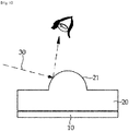
- a method of measuring undissolved substances is to apply a solution to a plate 10 with a blade and measure the number of gels 21 shown in the applied solution 20 in the light 30.
- the measurement method is different in its standard according to the measuring person, and measurement errors may occur even when the measurement is performed by the same person.
- the measurement method has a disadvantage in that the size of the gel by the undissolved substances cannot be measured, and thus there is a limit in determining whether the performance of the battery by the undissolved substances is lowered when an actual electrode is manufactured.
- an object of the present invention is to provide a method for measuring undissolved substances of a polymer solution, and more particularly, to provide a method for effectively measuring the number and size of gels by the undissolved substances by scraping and applying the polymer solution using a blade having a fixed interval, supplying light from the bottom and, at the same time, photographing the shape of light having passed through the solution from the top.
- the method for measuring undissolved substances of a polymer solution for achieving the above object may include a solution application step of applying a polymer solution on a transparent plate; a light supplying step of supplying light to the polymer solution applied on the transparent plate by a light source; a photographing step of photographing a shape of the light having penetrated the polymer solution applied on the transparent plate; and a measuring step of checking a number and a particle size of undissolved substances in the polymer solution with the photographed image.
- the polymer solution may be a polymer solution for preparing an electrode slurry of a secondary battery.
- the minimum measurable particle diameter of the undissolved substances may be 100 ⁇ m.
- the transparent plate may be made of OHP or glass.
- the solution can be applied by scraping the polymer solution with a blade.
- the gap from the transparent plate to the blade may be 80 to 200 ⁇ m, more preferably 100 to 150 ⁇ m, most preferably 110 ⁇ m to 140 ⁇ m.
- the light source may be located under the transparent plate.
- the light source may be a planar surface light source.
- the surface light source of the present invention may include the pattern for measuring the number and diameter of undissolved substances of the polymer solution on the upper part of the surface emitting light.
- the illuminance of the light source may be 750 to 1250 lux, more preferably 900 to 1100 lux.
- the photographing may be performed at an upper portion of the transparent plate.
- the method of measuring undissolved substances of a polymer solution according to the present invention has an effect of objectively measuring the size and number of gels by the undissolved substances of the polymer solution when preparing an electrode slurry through an image photographed by a test device.
- the method of measuring the undissolved substances of the polymer solution according to the present invention enables effective management of the undissolved substances in the prepared polymer solution for the slurry, thereby preventing the surface defect of the electrode and an increase in the resistance of the battery cell.
- the method for measuring the undissolved substances of a polymer solution of the present invention may include: a solution application step of applying a polymer solution on a transparent plate 100 (S1); a light supplying step of supplying light to the polymer solution applied on the transparent plate 100 by a light source 300 (S2); a photographing step of photographing a shape of the light having penetrated the polymer solution 200 applied on the transparent plate 100 (S3); and a measuring step of checking a number and a particle size of undissolved substances in the polymer solution with the photographed image (S4).
- any transparent material through which light is transmitted may be used as the material of the transparent plate 100, but the material is preferably OHP or glass.
- the polymer solution is evenly applied to the transparent plate 100.
- the transparent plate 100 should maintain a horizontal state with the ground in order to maintain the state of the applied polymer solution 200.
- the polymer solution may be a polymer solution for an electrode slurry for manufacturing a positive electrode or a negative electrode.
- the polymer solution for the electrode slurry may be a thickener or binder solution used in preparing the electrode slurry.
- the thickener may be one or more selected from the group consisting of Carboxymethyl cellulose (CMC), methyl cellulose (MC), hydroxypropyl cellulose (HPC), methyl hydroxypropyl cellulose (MHPC), ethyl hydroxyethyl cellulose (EHEC), methyl ethyl hydroxyethyl cellulose (MEHEC) and cellulose gum.
- CMC Carboxymethyl cellulose
- MC methyl cellulose
- HPC hydroxypropyl cellulose
- MHPC methyl hydroxypropyl cellulose
- EHEC ethyl hydroxyethyl cellulose
- MEHEC methyl ethyl hydroxyethyl cellulose
- the binder may be one or more selected from the group consisting of styrene-butadiene rubber (SBR), polyvinylidene fluoride (PVdF), copolymer of polyhexafluoropropylene-polyvinylidene fluoride (PVdF/HFP), poly (vinylacetate), polyvinyl alcohol, polyethylene oxide, polyvinylpyrrolidone, alkylated polyethylene oxide, polyvinyl ether, poly (methyl methacrylate), poly (ethyl acrylate), polytetrafluoroethylene (PTFE), polyvinylchloride, polyacrylonitrile, polyvinylpyridine, acrylonitrile-butadiene rubber and ethylene propylene diene monomer (EPDM).
- SBR styrene-butadiene rubber
- PVdF polyvinylidene fluoride
- PVdF/HFP copolymer of polyhexafluoropropylene-
- the number and particle diameter of the undissolved substances that may cause surface defects of the electrode and increased resistance of the secondary battery are measured.
- the minimum measurable particle diameter of the undissolved substances may be 100 ⁇ m.
- the solution can be applied by scraping the polymer solution with a blade.
- the application of the polymer solution should be made so that the light transmission is effective in the portion of the polymer solution where the undissolved substances do not exist, and the refraction of the light may be sufficiently observed in the portion of the polymer solution in which the undissolved substances exist.
- the gap from the transparent plate 100 to the blade may be 80 to 200 ⁇ m, more preferably 100 to 150 ⁇ m, most preferably 110 ⁇ m to 140 ⁇ m.
- the gap from the transparent plate to the blade means the distance from the transparent plate to the blade edge.
- the distance from the transparent plate to the blade is less than 80 ⁇ m, a hole may occur depending on the viscosity, and when the size of the undissolved substance is large, there is a problem that it is difficult to observe the refraction of light by scratching the surface.
- the distance from the transparent plate to the blade exceeds 200 ⁇ m and the coating is too thick, the undissolved substances may not be sufficiently detected, and therefore it is preferable to adjust the distance from the transparent plate to the blade to 80 to 200 ⁇ m for relative comparison between test samples.
- the light source 300 may be located below the transparent plate.
- the light source 300 can supply light evenly to the polymer solution 200 applied to the transparent plate 100, but the light source is preferably a planar surface light source which evenly supplies light to all areas of the applied polymer solution 200.
- the planar surface light source of the present invention may include a pattern 310 for measuring the undissolved substances for measuring the number of undissolved substances of the polymer solution and the area on the upper part of the surface emitting light.
- the pattern 310 for measuring the undissolved substances may be a pattern of a predetermined size printed on a transparent material that can transmit light, preferably a circular pattern for accurate measurement.
- the light emitted from the light source 300 in the light supplying step (S2) of the present invention passes through the pattern 310 for measuring the undissolved substances, the transparent plate 100, and the applied polymer solution 200 in order.
- the illuminance of the light source 300 is sufficient if it can sufficiently pass through the pattern 310 for measuring the undissolved substances, the transparent plate 100, and the applied polymer solution 200.
- it may be 750 to 1250 lux, more preferably 900 to 1100 lux.
- the surface of the solution remains evenly flat.
- the light emitted from the light source 300 passes through the portion having no undissolved substance, it passes through a path 301 without refraction.
- the light transmitted through the path 301 without refraction shows a shape 400 which projects the pattern 310 for measuring the undissolved substances as it is.
- the light emitted from the light source 300 passes through the portion having no undissolved substance, it passes through a path 301 without refraction.
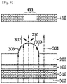
- Part of the light emitted from the light source is transmitted through a path (divergence, 302) refracted at the surface of the solution due to the bend 210 of the solution surface when there are undissolved substances in the applied polymer solution 200.
- Part of the light emitted from the light source is transmitted through a path (total reflection, 303) totally reflected at the surface of the solution due to the bend 210 of the solution surface when there are undissolved substances in the applied polymer solution 200.
- the light transmitted through the path 301 without refraction shows a shape 400 which projects the pattern 310 for measuring the undissolved substances as it is.
- the light transmitted through the refracting path 302 ambiguously projects the pattern 310 for measuring undissolved substances.
- the light transmitted through the completely reflecting path 303 does not project the pattern 310 for measuring the undissolved substances.
- a circular pattern is generally present in the background, and a blurred area covering the circular pattern is present in some places.
- the blurred area is an image which is generated as light irradiated from a light source is refracted by the bending of undissolved substances.
- the size of the pattern formed on the image is smaller than the size of the blurred area. Therefore, it is preferable that the size of the pattern formed on an image is equal to or less than 100 micrometers which is a minimum diameter which can be measured.
- the size of the pattern formed on the image can be adjusted by appropriately selecting the distance between the light source and the transparent plate. In one embodiment of the present invention, in order to adjust the size of the pattern formed on the image to 80 ⁇ m or less, the distance between the light source and the transparent plate was adjusted to a length of 0.3 to 1 meters.
- the photographing may be performed at an upper portion of the transparent plate.
- the light emitted from the light source penetrates the pattern 310 for measuring the undissolved substances, the transparent plate 100, and the applied polymer solution 200 through the path 301 without refraction, the refracting path 302, and the completely reflecting path 303.
- the light transmitted through the refracting path 302 ambiguously projects the pattern 310 for measuring undissolved substances.
- the light transmitted through the completely reflecting path 303 does not project the pattern 310 for measuring the undissolved substances.
- the shape of the projected light is photographed as an image.
- the image 410 when the undissolved substances exist in the applied polymer solution 200 is the same as the pattern shape of the pattern 310 for measuring the undissolved substances, but the portion where gels by the undissolved substances exist include a shape 411 which the boundary of the pattern is unclear.
- the number and particle size of the undissolved substances in the polymer solution are checked by analyzing the image photographed in the photographing step (S3).
- the number and the area (pixel) of the shapes 411, of which the boundary of the pattern is unclear with the bend 210 by the undissolved substances in the applied polymer solution in the photographed image, are measured, and they can be converted into the particle diameters of the undissolved substances through the area.
- the number of shapes 411 of which the boundary of the pattern is unclear means the number of undissolved substances in the polymer solution.
- the diameter of the shape 411 whose boundary of the pattern is unclear means the particle diameter of the undissolved substances in the polymer solution.
- An image conversion step of adjusting the contrast of the image may be further included in order to facilitate analysis of the image photographed in the photographing step S3 before the measuring step S4 of the present invention.
- the brightness of the unclear pattern 411 is lowered, so that the difference in brightness from the surrounding image becomes clearer, so that the number and particle size of the undissolved substances can be measured more accurately.
- a transparent plate of glass material was placed on top of the planar surface light source where the circular pattern was located, and the transparent plate was positioned to be about 1 m away from the planar surface light source, so that the diameter of the circular pattern formed thereon was adjusted to be 80 ⁇ m.
- the CMC solution (1.0 to 2.0% concentration solution dissolved in distilled water) was applied onto the transparent plate made of glass with a blade keeping a fixed distance of 100 ⁇ m from the transparent plate.
- FIG. 5 The image of the light emitted from the light source and transmitted through the CMC solution in the light supply step was photographed using the camera located on the transparent plate, and the photographed image is shown in FIG. 5 .
- the image was converted by adjusting the contrast in order to effectively measure the unclear portion of the photographed image.
- FIG. 6 shows an image converted from FIG. 5 by emphasizing contrast. As shown in FIGS. 5 and 6 , the brightness of the unclear portion of the image generated by the gel by the undissolved substances in the solution was minimized through the image conversion.
- a unique number is assigned to each of the parts in which the brightness of the converted image has been minimized, and pixel values of the image are measured for each unique number, and the results are shown in Table 1 below.
- Example 1 Example 2 ID number Pixel ID number Pixel 1 6689 1 2195 2 4709 2 889 3 1292 3 5611 4 1318 4 7367 5 3832 5 604 6 1550 6 1266 7 5438 7 4302 8 2995 8 3804 9 685 9 502 10 1698 10 611 11 507 11 3032 12 570 12 758 13 7311 13 3938 14 928 14 2350 15 8437 15 1212 16 1403 16 2251 17 2426 17 1355 18 996 18 789 19 543 19 1980 20 2296 20 2750 21 7288 22 5051 23 1218
- the CMC solution used in the above example 1 was checked by naked eyes, and the number of gels by the undissolved substances shown in the applied solution was measured.
- Example 2 When applying the CMC solution in Example 1, the solution was applied and light was supplied in the same manner as in Example 1 except that the distance between the transparent plate and the blade was adjusted to 250 ⁇ m. After that, it was tried to check the number and size of the undissolved substances, but because the CMC solution is too thick, the undissolved substances were completely covered by the CMC solution, and the number of the undissolved substances was shown as 6.
- the pattern formed in the image is clearly distinguished from the blurred area, there is an effect that there is no deviation in the number of the undissolved substances according to the testing person.
- the actual particle size value of the undissolved substances can be calculated based on the pixel value of the blurred area, there is an effect that the particle size of the undissolved substances can be measured.
Landscapes
- Chemical & Material Sciences (AREA)
- Biochemistry (AREA)
- Physics & Mathematics (AREA)
- Health & Medical Sciences (AREA)
- Life Sciences & Earth Sciences (AREA)
- Analytical Chemistry (AREA)
- Dispersion Chemistry (AREA)
- General Health & Medical Sciences (AREA)
- General Physics & Mathematics (AREA)
- Immunology (AREA)
- Pathology (AREA)
- Investigating Or Analysing Materials By Optical Means (AREA)
- Battery Electrode And Active Subsutance (AREA)
- Investigating Materials By The Use Of Optical Means Adapted For Particular Applications (AREA)
Abstract
Description
- This application claims the benefit of priority based on Korean Patent Application No.
10-2018-0090666, filed on August 3, 2018 - The present invention relates to a method for measuring undissolved substances of a polymer solution used in preparing an electrode slurry.
- Recently, secondary batteries capable of charging and discharging have been widely used as energy sources of wireless mobile devices. In addition, the secondary battery has attracted attention as an energy source of an electric vehicle, a hybrid electric vehicle, etc., which are proposed as a solution for air pollution of existing gasoline vehicles and diesel vehicles using fossil fuel. Therefore, the types of applications using the secondary battery are currently much diversified due to the advantages of the secondary battery, and it is expected that the secondary battery will be applied to many fields and products in the future.
- The secondary battery is formed by inserting an electrode assembly including a positive electrode, a separator, and a negative electrode in a pouch and injecting electrolyte therein. The positive electrode and the negative electrode constituting the electrode assembly of the secondary battery are formed by applying a positive electrode active material and a negative electrode active material on an electrode sheet.
- A lithium cobalt oxide, a lithium manganese oxide, a lithium nickel oxide, a lithium composite oxide, and the like are used as positive electrode active materials of the lithium secondary battery, and carbon materials are mainly used as negative electrode active materials and the use of silicon compounds and sulfur compounds as negative electrode active materials is also considered.
- In order to prepare an electrode of such a secondary battery, a slurry is prepared by dispersing an active material, a conductive material, a binder, and the like in a solvent. Therefore, the slurry is directly applied to the electrode current collector and dried to thereby form an electrode of the secondary battery. Alternatively, the slurry is applied on the upper part of a separate support and dried, and then a film peeled from the support is laminated on the current collector to thereby form an electrode of a secondary battery.
- In the case of the thickener or binder solution used to prepare an electrode slurry, since dissolution is performed not well, undissolved substances may be generated. Such undissolved substances may cause surface defects of electrodes and increased resistance of secondary batteries.
- Currently, in the case of thickeners or binder solutions in the manufacture of electrode slurries, as shown in
FIG. 1 , a method of measuring undissolved substances is to apply a solution to aplate 10 with a blade and measure the number ofgels 21 shown in the appliedsolution 20 in thelight 30. - The measurement method is different in its standard according to the measuring person, and measurement errors may occur even when the measurement is performed by the same person. In addition, the measurement method has a disadvantage in that the size of the gel by the undissolved substances cannot be measured, and thus there is a limit in determining whether the performance of the battery by the undissolved substances is lowered when an actual electrode is manufactured.
- Therefore, there is a need for a method that can more accurately determine the number of undissolved substances of a polymer solution used in the production of an electrode slurry.
- It is an object of the present invention to solve the above-mentioned problems of the prior art and the technical problems required from the past.
- Specifically, an object of the present invention is to provide a method for measuring undissolved substances of a polymer solution, and more particularly, to provide a method for effectively measuring the number and size of gels by the undissolved substances by scraping and applying the polymer solution using a blade having a fixed interval, supplying light from the bottom and, at the same time, photographing the shape of light having passed through the solution from the top.
- The method for measuring undissolved substances of a polymer solution for achieving the above object may include a solution application step of applying a polymer solution on a transparent plate; a light supplying step of supplying light to the polymer solution applied on the transparent plate by a light source; a photographing step of photographing a shape of the light having penetrated the polymer solution applied on the transparent plate; and a measuring step of checking a number and a particle size of undissolved substances in the polymer solution with the photographed image.
- In the present invention, the polymer solution may be a polymer solution for preparing an electrode slurry of a secondary battery.
- In the present invention, the minimum measurable particle diameter of the undissolved substances may be 100 µm.
- In the present invention, the transparent plate may be made of OHP or glass.
- In the solution application step of the present invention, the solution can be applied by scraping the polymer solution with a blade.
- In the step of applying the solution of the present invention, the gap from the transparent plate to the blade may be 80 to 200 µm, more preferably 100 to 150 µm, most preferably 110 µm to 140 µm.
- In the light supplying step of the present invention, the light source may be located under the transparent plate.
- In the light supplying step of the present invention, the light source may be a planar surface light source.
- The surface light source of the present invention may include the pattern for measuring the number and diameter of undissolved substances of the polymer solution on the upper part of the surface emitting light.
- In the light supplying step of the present invention, the illuminance of the light source may be 750 to 1250 lux, more preferably 900 to 1100 lux.
- In the photographing step of the present invention, the photographing may be performed at an upper portion of the transparent plate.
- The method of measuring undissolved substances of a polymer solution according to the present invention has an effect of objectively measuring the size and number of gels by the undissolved substances of the polymer solution when preparing an electrode slurry through an image photographed by a test device.
- In addition, the method of measuring the undissolved substances of the polymer solution according to the present invention enables effective management of the undissolved substances in the prepared polymer solution for the slurry, thereby preventing the surface defect of the electrode and an increase in the resistance of the battery cell.
-
-
FIG. 1 is a schematic diagram showing a conventional method for measuring the number of undissolved substances when preparing a slurry. -
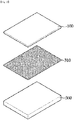
FIG. 2 is a perspective view showing the relative positions of a transparent plate, a pattern for measuring undissolved substances, and a light source in a method for measuring undissolved substances according to an embodiment of the present invention. -
FIG. 3 is a side view showing a measurement when there is no undissolved substance in a polymer solution using a undissolved substance measurement method of a polymer solution according to an embodiment of the present invention. -
FIG. 4 is a side view showing a measurement when there is are undissolved substances in a polymer solution using a undissolved substance measurement method of a polymer solution according to an embodiment of the present invention. -
FIG. 5 shows an image of a polymer solution taken according to an embodiment of the present invention. -
FIG. 6 shows an image converted by adjusting the brightness contrast of the image ofFIG. 5 photographed according to an embodiment of the present invention. -
FIG. 7 is a flowchart showing the procedure of a method for measuring undissolved substances of a polymer solution of the present invention. - Hereinafter, embodiments of the present invention will be described with reference to the drawings. However, the present invention is not limited by the scope of the embodiments of present invention.
- A method for measuring undissolved substances of a polymer solution according to the present invention will be described with reference to the flowchart of
FIG. 7 and FIGS. 2 to 4 . - As shown in
FIG. 7 , the method for measuring the undissolved substances of a polymer solution of the present invention may include: a solution application step of applying a polymer solution on a transparent plate 100 (S1); a light supplying step of supplying light to the polymer solution applied on thetransparent plate 100 by a light source 300 (S2); a photographing step of photographing a shape of the light having penetrated thepolymer solution 200 applied on the transparent plate 100 (S3); and a measuring step of checking a number and a particle size of undissolved substances in the polymer solution with the photographed image (S4). - First, in the solution applying step S1 of applying a polymer solution on the
transparent plate 100, any transparent material through which light is transmitted may be used as the material of thetransparent plate 100, but the material is preferably OHP or glass. - The polymer solution is evenly applied to the
transparent plate 100. Thetransparent plate 100 should maintain a horizontal state with the ground in order to maintain the state of the appliedpolymer solution 200. - The polymer solution may be a polymer solution for an electrode slurry for manufacturing a positive electrode or a negative electrode. The polymer solution for the electrode slurry may be a thickener or binder solution used in preparing the electrode slurry.
- The thickener may be one or more selected from the group consisting of Carboxymethyl cellulose (CMC), methyl cellulose (MC), hydroxypropyl cellulose (HPC), methyl hydroxypropyl cellulose (MHPC), ethyl hydroxyethyl cellulose (EHEC), methyl ethyl hydroxyethyl cellulose (MEHEC) and cellulose gum.
- The binder may be one or more selected from the group consisting of styrene-butadiene rubber (SBR), polyvinylidene fluoride (PVdF), copolymer of polyhexafluoropropylene-polyvinylidene fluoride (PVdF/HFP), poly (vinylacetate), polyvinyl alcohol, polyethylene oxide, polyvinylpyrrolidone, alkylated polyethylene oxide, polyvinyl ether, poly (methyl methacrylate), poly (ethyl acrylate), polytetrafluoroethylene (PTFE), polyvinylchloride, polyacrylonitrile, polyvinylpyridine, acrylonitrile-butadiene rubber and ethylene propylene diene monomer (EPDM).
- In the present invention, the number and particle diameter of the undissolved substances that may cause surface defects of the electrode and increased resistance of the secondary battery are measured. The minimum measurable particle diameter of the undissolved substances may be 100 µm.
- In the solution application step (S1), the solution can be applied by scraping the polymer solution with a blade. The application of the polymer solution should be made so that the light transmission is effective in the portion of the polymer solution where the undissolved substances do not exist, and the refraction of the light may be sufficiently observed in the portion of the polymer solution in which the undissolved substances exist.
- In the step of applying the solution, the gap from the
transparent plate 100 to the blade may be 80 to 200 µm, more preferably 100 to 150 µm, most preferably 110 µm to 140 µm. The gap from the transparent plate to the blade means the distance from the transparent plate to the blade edge. - When the distance from the transparent plate to the blade is less than 80 µm, a hole may occur depending on the viscosity, and when the size of the undissolved substance is large, there is a problem that it is difficult to observe the refraction of light by scratching the surface. In the case where the distance from the transparent plate to the blade exceeds 200 µm and the coating is too thick, the undissolved substances may not be sufficiently detected, and therefore it is preferable to adjust the distance from the transparent plate to the blade to 80 to 200 µm for relative comparison between test samples.
- Next, in the light supply step S2 of supplying light to the
polymer solution 200 applied on thetransparent plate 100 by thelight source 300, thelight source 300 may be located below the transparent plate. - It is sufficient if the
light source 300 can supply light evenly to thepolymer solution 200 applied to thetransparent plate 100, but the light source is preferably a planar surface light source which evenly supplies light to all areas of the appliedpolymer solution 200. - The planar surface light source of the present invention may include a
pattern 310 for measuring the undissolved substances for measuring the number of undissolved substances of the polymer solution and the area on the upper part of the surface emitting light. - The
pattern 310 for measuring the undissolved substances may be a pattern of a predetermined size printed on a transparent material that can transmit light, preferably a circular pattern for accurate measurement. - As illustrated in
FIGS. 3 and4 , the light emitted from thelight source 300 in the light supplying step (S2) of the present invention passes through thepattern 310 for measuring the undissolved substances, thetransparent plate 100, and the appliedpolymer solution 200 in order. - In the light supply step of the present invention, the illuminance of the
light source 300 is sufficient if it can sufficiently pass through thepattern 310 for measuring the undissolved substances, thetransparent plate 100, and the appliedpolymer solution 200. Preferably, it may be 750 to 1250 lux, more preferably 900 to 1100 lux. - As shown in
FIG. 3 , when there is no undissolved substance in the appliedpolymer solution 200, the surface of the solution remains evenly flat. When the light emitted from thelight source 300 passes through the portion having no undissolved substance, it passes through apath 301 without refraction. The light transmitted through thepath 301 without refraction shows ashape 400 which projects thepattern 310 for measuring the undissolved substances as it is. - On the other hand, as shown in
FIG. 4 , when there are undissolved substances in the appliedpolymer solution 200, the undissolved substances generate abend 210 by a gel on the surface of the solution. - When the light emitted from the
light source 300 passes through the portion having no undissolved substance, it passes through apath 301 without refraction. Part of the light emitted from the light source is transmitted through a path (divergence, 302) refracted at the surface of the solution due to thebend 210 of the solution surface when there are undissolved substances in the appliedpolymer solution 200. Part of the light emitted from the light source is transmitted through a path (total reflection, 303) totally reflected at the surface of the solution due to thebend 210 of the solution surface when there are undissolved substances in the appliedpolymer solution 200. - The light transmitted through the
path 301 without refraction shows ashape 400 which projects thepattern 310 for measuring the undissolved substances as it is. On the other hand, the light transmitted through the refractingpath 302 ambiguously projects thepattern 310 for measuring undissolved substances. In addition, the light transmitted through the completely reflectingpath 303 does not project thepattern 310 for measuring the undissolved substances. - Referring to
FIGS. 5 and6 , a circular pattern is generally present in the background, and a blurred area covering the circular pattern is present in some places. As described above, the blurred area is an image which is generated as light irradiated from a light source is refracted by the bending of undissolved substances. In order for the undissolved substances to be easily distinguished, it is desirable that the size of the pattern formed on the image is smaller than the size of the blurred area. Therefore, it is preferable that the size of the pattern formed on an image is equal to or less than 100 micrometers which is a minimum diameter which can be measured. The size of the pattern formed on the image can be adjusted by appropriately selecting the distance between the light source and the transparent plate. In one embodiment of the present invention, in order to adjust the size of the pattern formed on the image to 80µm or less, the distance between the light source and the transparent plate was adjusted to a length of 0.3 to 1 meters. - In the photographing step S3 of the present invention, the photographing may be performed at an upper portion of the transparent plate.
- As shown in
FIG. 3 , when no undissolved substance exists in the appliedpolymer solution 200, all of the light emitted from the light source passes through thepattern 310 for measuring the undissolved substances, thetransparent plate 100, the appliedpolymer solution 200 through thepath 301 without refraction, to thereby project the pattern shape of thepattern 310 for measuring the undissolved substances as it is. In the photographing step, the shape of the projected light is photographed as an image. Theimage 400 when no undissolved substance exists in the appliedpolymer solution 200 is the same as the pattern shape of thepattern 310 for measuring the undissolved substance. - As shown in
FIG. 4 , when undissolved substances exist in the appliedpolymer solution 200, the light emitted from the light source penetrates thepattern 310 for measuring the undissolved substances, thetransparent plate 100, and the appliedpolymer solution 200 through thepath 301 without refraction, the refractingpath 302, and the completely reflectingpath 303. - The light transmitted through the refracting
path 302 ambiguously projects thepattern 310 for measuring undissolved substances. In addition, the light transmitted through the completely reflectingpath 303 does not project thepattern 310 for measuring the undissolved substances. In the photographing step, the shape of the projected light is photographed as an image. Theimage 410 when the undissolved substances exist in the appliedpolymer solution 200 is the same as the pattern shape of thepattern 310 for measuring the undissolved substances, but the portion where gels by the undissolved substances exist include ashape 411 which the boundary of the pattern is unclear. - In the measuring step (S4) of checking the number and particle size of the undissolved substances in the polymer solution with the photographed image of the present invention, the number and particle size of the undissolved substances in the polymer solution are checked by analyzing the image photographed in the photographing step (S3).
- As shown in
FIG. 4 , in the measuring step (S4), the number and the area (pixel) of theshapes 411, of which the boundary of the pattern is unclear with thebend 210 by the undissolved substances in the applied polymer solution in the photographed image, are measured, and they can be converted into the particle diameters of the undissolved substances through the area. - The number of
shapes 411 of which the boundary of the pattern is unclear means the number of undissolved substances in the polymer solution. The diameter of theshape 411 whose boundary of the pattern is unclear means the particle diameter of the undissolved substances in the polymer solution. - An image conversion step of adjusting the contrast of the image may be further included in order to facilitate analysis of the image photographed in the photographing step S3 before the measuring step S4 of the present invention. Through the image conversion step, the brightness of the
unclear pattern 411 is lowered, so that the difference in brightness from the surrounding image becomes clearer, so that the number and particle size of the undissolved substances can be measured more accurately. - Hereinafter, the present invention will be described in detail with reference to Examples. However, the following Examples are only for illustrating the present invention, and the present invention is not limited by the following Examples.
- A circular pattern, in which circles are repeated, was positioned on the planar surface light source having an illuminance of 1000 lux. A transparent plate of glass material was placed on top of the planar surface light source where the circular pattern was located, and the transparent plate was positioned to be about 1 m away from the planar surface light source, so that the diameter of the circular pattern formed thereon was adjusted to be 80 µm.
- The CMC solution (1.0 to 2.0% concentration solution dissolved in distilled water) was applied onto the transparent plate made of glass with a blade keeping a fixed distance of 100 µm from the transparent plate.
- 1000 lux of light was supplied through the planar surface light source from the bottom of the transparent plate coated with the CMC solution.
- The image of the light emitted from the light source and transmitted through the CMC solution in the light supply step was photographed using the camera located on the transparent plate, and the photographed image is shown in
FIG. 5 . The image was converted by adjusting the contrast in order to effectively measure the unclear portion of the photographed image.FIG. 6 shows an image converted fromFIG. 5 by emphasizing contrast. As shown inFIGS. 5 and6 , the brightness of the unclear portion of the image generated by the gel by the undissolved substances in the solution was minimized through the image conversion. - In the measuring step, a unique number is assigned to each of the parts in which the brightness of the converted image has been minimized, and pixel values of the image are measured for each unique number, and the results are shown in Table 1 below.
- When applying the CMC solution in Example 1, the number and the size of undissolved substances were checked in the same manner as in Example 1 except that the distance between the transparent plate and the blade was adjusted to 150 µm, and the result was shown in Table 1.
[Table 1] Example 1 Example 2 ID number Pixel ID number Pixel 1 6689 1 2195 2 4709 2 889 3 1292 3 5611 4 1318 4 7367 5 3832 5 604 6 1550 6 1266 7 5438 7 4302 8 2995 8 3804 9 685 9 502 10 1698 10 611 11 507 11 3032 12 570 12 758 13 7311 13 3938 14 928 14 2350 15 8437 15 1212 16 1403 16 2251 17 2426 17 1355 18 996 18 789 19 543 19 1980 20 2296 20 2750 21 7288 22 5051 23 1218 - The CMC solution used in the above example 1 was checked by naked eyes, and the number of gels by the undissolved substances shown in the applied solution was measured.
- The measurements were carried out four times by three different testing persons each. The number of undissolved substances measured is shown in Table 2 below.
[Table 2] No. of measurement Testing person 1 Testing person 2 Testing person 3 1 21 13 22 2 16 19 26 3 20 15 30 4 25 22 33 Average 20.5 17.25 27.75 - As can be seen from the test results of Comparative Example 1, the measurement method by naked eyes showed different measurement values, depending on each round of measurement performed by one testing person for the same measurement target. In addition, since the criteria of undissolved substances are different for each testing person, different averages are shown at the measurement of the undissolved substances in the solution. In addition, visual inspection could not measure the size of the undissolved substances.
- When applying the CMC solution in Example 1, the solution was applied and light was supplied in the same manner as in Example 1 except that the distance between the transparent plate and the blade was adjusted to 250 µm. After that, it was tried to check the number and size of the undissolved substances, but because the CMC solution is too thick, the undissolved substances were completely covered by the CMC solution, and the number of the undissolved substances was shown as 6.
- As described above, in the method of measuring the undissolved substances in the polymer solution according to an embodiment of the present invention, since the pattern formed in the image is clearly distinguished from the blurred area, there is an effect that there is no deviation in the number of the undissolved substances according to the testing person. In addition, since the actual particle size value of the undissolved substances can be calculated based on the pixel value of the blurred area, there is an effect that the particle size of the undissolved substances can be measured.
- It will be understood by those skilled in the art that various changes in form and details may be made therein without departing from the spirit and scope of the invention as defined by the appended claims.
Claims (13)
- A method for measuring undissolved substances of a polymer solution, the method comprising:a solution application step of applying a polymer solution on a transparent plate;a light supplying step of supplying light to the polymer solution applied on the transparent plate by a light source;a photographing step of photographing a shape of the light having penetrated the polymer solution applied on the transparent plate; anda measuring step of checking a number and a particle size of undissolved substances in the polymer solution with the photographed image.
- The method of claim 1, wherein the polymer solution is a polymer solution for preparing a secondary battery electrode slurry.
- The method of claim 1, wherein a minimum measurable particle size of the undissolved substances is 100 µm.
- The method of claim 1, wherein the transparent plate is made of Over Head Projector (OHP) or glass.
- The method of claim 1, wherein in the solution applying step, the polymer solution is scraped by a blade to thereby be applied.
- The method of claim 5, wherein a distance from the transparent plate to the blade is 80 to 200 µm.
- The method of claim 5, wherein a distance from the transparent plate to the blade is 100 to 150 µm.
- The method of claim 1, wherein the light source is positioned under the transparent plate in the light supplying step.
- The method of claim 1, wherein the light source in the light supplying step is a planar surface light source.
- The method of claim 9, wherein the planar surface light source in the light supplying step comprises a pattern for measuring the undissolved substances of the polymer solution on an upper part of the surface emitting light.
- The method of claim 1, wherein an illuminance of the light source in the light supplying step is 750 to 1250 lux.
- The method of claim 1, wherein an illuminance of the light source in the light supplying step is 900 to 1100 lux.
- The method of claim 1, wherein the photographing in the photographing step is performed on an upper portion of the transparent plate.
Applications Claiming Priority (2)
| Application Number | Priority Date | Filing Date | Title |
|---|---|---|---|
| KR1020180090666A KR102309284B1 (en) | 2018-08-03 | 2018-08-03 | Method of measument for undissolved solutes in polymer solution |
| PCT/KR2019/009538 WO2020027573A1 (en) | 2018-08-03 | 2019-07-31 | Method for measuring undissolved material in polymer solution |
Publications (3)
| Publication Number | Publication Date |
|---|---|
| EP3702754A1 true EP3702754A1 (en) | 2020-09-02 |
| EP3702754A4 EP3702754A4 (en) | 2021-03-03 |
| EP3702754B1 EP3702754B1 (en) | 2024-04-24 |
Family
ID=69232614
Family Applications (1)
| Application Number | Title | Priority Date | Filing Date |
|---|---|---|---|
| EP19845245.0A Active EP3702754B1 (en) | 2018-08-03 | 2019-07-31 | Method for measuring undissolved material in polymer solution |
Country Status (8)
| Country | Link |
|---|---|
| US (1) | US11092533B2 (en) |
| EP (1) | EP3702754B1 (en) |
| KR (1) | KR102309284B1 (en) |
| CN (1) | CN111417848B (en) |
| ES (1) | ES2988891T3 (en) |
| HU (1) | HUE067190T2 (en) |
| PL (1) | PL3702754T3 (en) |
| WO (1) | WO2020027573A1 (en) |
Families Citing this family (1)
| Publication number | Priority date | Publication date | Assignee | Title |
|---|---|---|---|---|
| CN113640197A (en) * | 2021-10-19 | 2021-11-12 | 高密银鹰新材料股份有限公司 | Detection method of cellulose ether semi-finished product |
Family Cites Families (37)
| Publication number | Priority date | Publication date | Assignee | Title |
|---|---|---|---|---|
| US3992096A (en) * | 1975-08-04 | 1976-11-16 | Minnesota Mining And Manufacturing Company | Detecting system |
| JPS5937444A (en) * | 1982-08-25 | 1984-02-29 | Showa Mfg Co Ltd | How to measure particulates in hydraulic oil |
| JPS5937444U (en) * | 1982-09-02 | 1984-03-09 | 曙ブレーキ工業株式会社 | Disc brake pad lining wear warning device |
| US4555662A (en) * | 1983-03-03 | 1985-11-26 | Limca Research Inc. | Method and apparatus for the detection and measurement of particulates in molten metal |
| JP2846823B2 (en) | 1994-11-29 | 1999-01-13 | 第一工業製薬株式会社 | Method for counting the number of insolubles in aqueous solution of carboxymethyl cellulose ether alkaline salt |
| EP1151139A2 (en) * | 1999-01-25 | 2001-11-07 | UT-Battelle, LLC | Multifunctional and multispectral biosensor devices and methods of use |
| GB2355947B (en) * | 1999-07-23 | 2002-02-20 | Murata Manufacturing Co | Method of producing ceramic slurry, ceramic slurry composition, ceramic green sheet and multilayer ceramic electronic part |
| CA2404560A1 (en) * | 2000-03-31 | 2001-10-11 | Sergey Makarov | Systems for detecting and measuring inclusions |
| US7425310B2 (en) * | 2004-01-29 | 2008-09-16 | Bryan Truex | Apparatus, system, and method of detecting an analyte utilizing pyroelectric technology |
| JP4214933B2 (en) * | 2004-03-19 | 2009-01-28 | 株式会社豊田中央研究所 | Liquid viscosity measuring device and viscosity measuring method |
| JP2006308284A (en) * | 2004-03-31 | 2006-11-09 | Kitakyushu Foundation For The Advancement Of Industry Science & Technology | Suspended particulate collector and method for producing the same |
| CA2470887C (en) | 2004-06-14 | 2014-10-21 | Nova Chemicals Corporation | Detection of gels in a solution polymerization |
| KR100945392B1 (en) * | 2008-05-28 | 2010-03-04 | 엘지전자 주식회사 | Optical sheet, backlight unit and liquid crystal display including the same |
| KR20100093215A (en) * | 2009-02-16 | 2010-08-25 | (주)위시스 | System for inspecting status of sealer application and method of the same |
| WO2010117102A1 (en) * | 2009-04-09 | 2010-10-14 | 서강대학교 산학협력단 | Method for aligning colloidal crystals as single crystals |
| KR101120049B1 (en) * | 2009-08-14 | 2012-03-23 | (주)아이콘 | Method and Apparatus for Glass Sealant Inspection |
| WO2011128963A1 (en) * | 2010-04-12 | 2011-10-20 | トヨタ自動車株式会社 | Method for producing battery electrode |
| CN103025859A (en) * | 2010-05-25 | 2013-04-03 | 阿尔利克斯公司 | Methods and apparatuses for detection of positional freedom of particles in biological and chemical analyses and applications in immunodiagnostics |
| KR101466628B1 (en) * | 2011-08-08 | 2014-11-28 | 주식회사 엘지화학 | Analysis Method of Metal Impurity By Electrochemical Method |
| TWI582408B (en) * | 2011-08-29 | 2017-05-11 | 安美基公司 | Method and apparatus for non-destructive detection - undissolved particles in a fluid |
| KR101369326B1 (en) * | 2011-12-27 | 2014-03-04 | 주식회사 엘지화학 | Preparation method of separator, separator formed therefrom, and electrochemical device containing the same |
| KR20120101622A (en) * | 2012-08-29 | 2012-09-14 | (주)쎄미시스코 | System and method of measuring irregullarity of a glass plate |
| KR101425855B1 (en) * | 2013-02-21 | 2014-08-14 | 서울대학교산학협력단 | Electroconductive ink composite including metal-organic precursor and method for Forming the metal line using the same |
| JP6028628B2 (en) | 2013-03-08 | 2016-11-16 | 株式会社豊田自動織機 | Electrode manufacturing equipment |
| JP6236736B2 (en) * | 2013-07-29 | 2017-11-29 | 三菱ケミカル株式会社 | Anomaly detection apparatus and anomaly detection method for film forming stock solution |
| KR20150022359A (en) * | 2013-08-23 | 2015-03-04 | 와이즈플래닛(주) | Inspection-Object Location estimation device using multi camera. |
| DE202014100974U1 (en) | 2014-03-04 | 2015-06-08 | Retsch Technology Gmbh | Device for determining the particle size and / or the particle shape of a particle mixture |
| KR101582461B1 (en) * | 2014-10-22 | 2016-01-05 | 주식회사 제덱스 | Test film for detecting surface particles in clean room |
| FR3037143B1 (en) * | 2015-06-05 | 2019-08-02 | Universite Joseph Fourier | SINGLE CAMERA DEVICE AND MEASURING METHOD FOR CHARACTERIZING RAIN DROPS |
| CN105600258A (en) | 2015-11-02 | 2016-05-25 | 浙江斐尔德智能设备有限公司 | Stereoscopic warehouse stacking machine and automatic stereoscopic warehouse |
| JP6936984B2 (en) * | 2016-01-19 | 2021-09-22 | 東ソー株式会社 | How to Predict the Prognosis of Cancer Patients Using Rare Cells |
| KR101793559B1 (en) | 2016-01-26 | 2017-11-03 | 윈포시스(주) | Particle Analyzer Microscope |
| CN105699258B (en) * | 2016-01-28 | 2018-06-19 | 华侨大学 | A kind of fine aggregate on-line measuring device and method |
| WO2018100780A1 (en) * | 2016-11-30 | 2018-06-07 | 国立研究開発法人産業技術総合研究所 | Target substance detection device and target substance detection method |
| KR102055593B1 (en) | 2017-02-03 | 2019-12-13 | 삼성전자주식회사 | Fan-out semiconductor package |
| EP3623411A4 (en) * | 2017-05-12 | 2021-01-20 | Toray Industries, Inc. | PROCESS FOR PRODUCING FINE PARTICLES FROM POLYAMIDE AND FINE PARTICLES FROM POLYAMIDE |
| US11609224B2 (en) * | 2017-10-26 | 2023-03-21 | Essenlix Corporation | Devices and methods for white blood cell analyses |
-
2018
- 2018-08-03 KR KR1020180090666A patent/KR102309284B1/en active Active
-
2019
- 2019-07-31 WO PCT/KR2019/009538 patent/WO2020027573A1/en not_active Ceased
- 2019-07-31 EP EP19845245.0A patent/EP3702754B1/en active Active
- 2019-07-31 CN CN201980006007.5A patent/CN111417848B/en active Active
- 2019-07-31 PL PL19845245.0T patent/PL3702754T3/en unknown
- 2019-07-31 US US16/767,166 patent/US11092533B2/en active Active
- 2019-07-31 HU HUE19845245A patent/HUE067190T2/en unknown
- 2019-07-31 ES ES19845245T patent/ES2988891T3/en active Active
Also Published As
| Publication number | Publication date |
|---|---|
| HUE067190T2 (en) | 2024-10-28 |
| PL3702754T3 (en) | 2024-07-01 |
| US11092533B2 (en) | 2021-08-17 |
| CN111417848B (en) | 2023-06-30 |
| WO2020027573A1 (en) | 2020-02-06 |
| EP3702754B1 (en) | 2024-04-24 |
| KR20200015186A (en) | 2020-02-12 |
| CN111417848A (en) | 2020-07-14 |
| EP3702754A4 (en) | 2021-03-03 |
| US20200386663A1 (en) | 2020-12-10 |
| ES2988891T3 (en) | 2024-11-22 |
| KR102309284B1 (en) | 2021-10-06 |
Similar Documents
| Publication | Publication Date | Title |
|---|---|---|
| KR102206908B1 (en) | Inspection apparatus and method for separation film of secondary battery | |
| KR102953920B1 (en) | System for inspecting battery cell and method for inspecting battery cell | |
| US12209805B2 (en) | Electrode drying device and electrode drying method | |
| CN109945776B (en) | Displacement/strain measurement method based on fluorescent particle marking and active optical measurement in electrochemistry | |
| CN110609040B (en) | Optical detection method of diaphragm | |
| ES3058016T3 (en) | Thin film specimen for tensile test and physical property evaluation method for thin film specimen | |
| CN114740001A (en) | Lithium battery pole piece size detection device and method | |
| CN101382489B (en) | A method for evaluating the stability of slurry | |
| CN110261380A (en) | An In Situ Synchronous Observation System of Lithium-ion Battery Electrode Reaction | |
| CN111141755A (en) | A method for detecting internal defects of battery cells | |
| CN106623493B (en) | A kind of detection method of steel band punching Continuous maching | |
| CN107167463A (en) | A qualitative and homogeneous analysis method for rubber-coated separator materials in lithium-ion batteries | |
| CN113702248A (en) | Method for testing wettability of diaphragms made of different materials for lithium ion battery | |
| KR20230014971A (en) | Inspection Method and Device for Aluminum Pouch Thickness of Lithium Ion Battery | |
| US12298229B2 (en) | Dry quality evaluation device for electrode and dry quality evaluation method for electrode | |
| US11092533B2 (en) | Method for measuring undissolved material in polymer solution | |
| CN217359628U (en) | Lithium battery pole piece size detection device | |
| CN208937645U (en) | Testing device | |
| KR102733844B1 (en) | Method for Inspecting Tabs on Pouched Batteries | |
| CN107576668A (en) | A kind of CCD on-line detecting systems and method | |
| JP2001283935A (en) | Battery sealing structure inspection method and battery sealing structure inspection device | |
| CN116759322A (en) | Method to monitor the uniformity of poly process on the back of topcon battery | |
| EP4664094A1 (en) | Device for testing dryness of electrode and method for testing dryness of electrode | |
| CN217466745U (en) | Sample stage device for characterization of scanning electron microscope of lead storage battery electrode plate | |
| CN218674776U (en) | Lithium battery pole piece surface flaw detection machine |
Legal Events
| Date | Code | Title | Description |
|---|---|---|---|
| STAA | Information on the status of an ep patent application or granted ep patent |
Free format text: STATUS: THE INTERNATIONAL PUBLICATION HAS BEEN MADE |
|
| PUAI | Public reference made under article 153(3) epc to a published international application that has entered the european phase |
Free format text: ORIGINAL CODE: 0009012 |
|
| STAA | Information on the status of an ep patent application or granted ep patent |
Free format text: STATUS: REQUEST FOR EXAMINATION WAS MADE |
|
| 17P | Request for examination filed |
Effective date: 20200526 |
|
| AK | Designated contracting states |
Kind code of ref document: A1 Designated state(s): AL AT BE BG CH CY CZ DE DK EE ES FI FR GB GR HR HU IE IS IT LI LT LU LV MC MK MT NL NO PL PT RO RS SE SI SK SM TR |
|
| AX | Request for extension of the european patent |
Extension state: BA ME |
|
| A4 | Supplementary search report drawn up and despatched |
Effective date: 20210129 |
|
| RIC1 | Information provided on ipc code assigned before grant |
Ipc: G01N 15/02 20060101AFI20210125BHEP Ipc: G01N 15/10 20060101ALI20210125BHEP |
|
| DAV | Request for validation of the european patent (deleted) | ||
| DAX | Request for extension of the european patent (deleted) | ||
| RAP1 | Party data changed (applicant data changed or rights of an application transferred) |
Owner name: LG ENERGY SOLUTION LTD. |
|
| RAP3 | Party data changed (applicant data changed or rights of an application transferred) |
Owner name: LG ENERGY SOLUTION, LTD. |
|
| STAA | Information on the status of an ep patent application or granted ep patent |
Free format text: STATUS: EXAMINATION IS IN PROGRESS |
|
| 17Q | First examination report despatched |
Effective date: 20221004 |
|
| GRAP | Despatch of communication of intention to grant a patent |
Free format text: ORIGINAL CODE: EPIDOSNIGR1 |
|
| STAA | Information on the status of an ep patent application or granted ep patent |
Free format text: STATUS: GRANT OF PATENT IS INTENDED |
|
| GRAS | Grant fee paid |
Free format text: ORIGINAL CODE: EPIDOSNIGR3 |
|
| INTG | Intention to grant announced |
Effective date: 20240221 |
|
| GRAA | (expected) grant |
Free format text: ORIGINAL CODE: 0009210 |
|
| STAA | Information on the status of an ep patent application or granted ep patent |
Free format text: STATUS: THE PATENT HAS BEEN GRANTED |
|
| P01 | Opt-out of the competence of the unified patent court (upc) registered |
Effective date: 20240301 |
|
| AK | Designated contracting states |
Kind code of ref document: B1 Designated state(s): AL AT BE BG CH CY CZ DE DK EE ES FI FR GB GR HR HU IE IS IT LI LT LU LV MC MK MT NL NO PL PT RO RS SE SI SK SM TR |
|
| REG | Reference to a national code |
Ref country code: GB Ref legal event code: FG4D |
|
| REG | Reference to a national code |
Ref country code: CH Ref legal event code: EP |
|
| REG | Reference to a national code |
Ref country code: DE Ref legal event code: R096 Ref document number: 602019051057 Country of ref document: DE |
|
| REG | Reference to a national code |
Ref country code: IE Ref legal event code: FG4D |
|
| REG | Reference to a national code |
Ref country code: SE Ref legal event code: TRGR |
|
| REG | Reference to a national code |
Ref country code: LT Ref legal event code: MG9D |
|
| REG | Reference to a national code |
Ref country code: NL Ref legal event code: MP Effective date: 20240424 |
|
| REG | Reference to a national code |
Ref country code: AT Ref legal event code: MK05 Ref document number: 1680077 Country of ref document: AT Kind code of ref document: T Effective date: 20240424 |
|
| PG25 | Lapsed in a contracting state [announced via postgrant information from national office to epo] |
Ref country code: NL Free format text: LAPSE BECAUSE OF FAILURE TO SUBMIT A TRANSLATION OF THE DESCRIPTION OR TO PAY THE FEE WITHIN THE PRESCRIBED TIME-LIMIT Effective date: 20240424 |
|
| PG25 | Lapsed in a contracting state [announced via postgrant information from national office to epo] |
Ref country code: NL Free format text: LAPSE BECAUSE OF FAILURE TO SUBMIT A TRANSLATION OF THE DESCRIPTION OR TO PAY THE FEE WITHIN THE PRESCRIBED TIME-LIMIT Effective date: 20240424 |
|
| PG25 | Lapsed in a contracting state [announced via postgrant information from national office to epo] |
Ref country code: IS Free format text: LAPSE BECAUSE OF FAILURE TO SUBMIT A TRANSLATION OF THE DESCRIPTION OR TO PAY THE FEE WITHIN THE PRESCRIBED TIME-LIMIT Effective date: 20240824 |
|
| PG25 | Lapsed in a contracting state [announced via postgrant information from national office to epo] |
Ref country code: BG Free format text: LAPSE BECAUSE OF FAILURE TO SUBMIT A TRANSLATION OF THE DESCRIPTION OR TO PAY THE FEE WITHIN THE PRESCRIBED TIME-LIMIT Effective date: 20240424 |
|
| PG25 | Lapsed in a contracting state [announced via postgrant information from national office to epo] |
Ref country code: FI Free format text: LAPSE BECAUSE OF FAILURE TO SUBMIT A TRANSLATION OF THE DESCRIPTION OR TO PAY THE FEE WITHIN THE PRESCRIBED TIME-LIMIT Effective date: 20240424 Ref country code: HR Free format text: LAPSE BECAUSE OF FAILURE TO SUBMIT A TRANSLATION OF THE DESCRIPTION OR TO PAY THE FEE WITHIN THE PRESCRIBED TIME-LIMIT Effective date: 20240424 |
|
| PG25 | Lapsed in a contracting state [announced via postgrant information from national office to epo] |
Ref country code: GR Free format text: LAPSE BECAUSE OF FAILURE TO SUBMIT A TRANSLATION OF THE DESCRIPTION OR TO PAY THE FEE WITHIN THE PRESCRIBED TIME-LIMIT Effective date: 20240725 |
|
| PG25 | Lapsed in a contracting state [announced via postgrant information from national office to epo] |
Ref country code: PT Free format text: LAPSE BECAUSE OF FAILURE TO SUBMIT A TRANSLATION OF THE DESCRIPTION OR TO PAY THE FEE WITHIN THE PRESCRIBED TIME-LIMIT Effective date: 20240826 |
|
| PG25 | Lapsed in a contracting state [announced via postgrant information from national office to epo] |
Ref country code: AT Free format text: LAPSE BECAUSE OF FAILURE TO SUBMIT A TRANSLATION OF THE DESCRIPTION OR TO PAY THE FEE WITHIN THE PRESCRIBED TIME-LIMIT Effective date: 20240424 |
|
| REG | Reference to a national code |
Ref country code: HU Ref legal event code: AG4A Ref document number: E067190 Country of ref document: HU |
|
| PG25 | Lapsed in a contracting state [announced via postgrant information from national office to epo] |
Ref country code: LV Free format text: LAPSE BECAUSE OF FAILURE TO SUBMIT A TRANSLATION OF THE DESCRIPTION OR TO PAY THE FEE WITHIN THE PRESCRIBED TIME-LIMIT Effective date: 20240424 |
|
| PG25 | Lapsed in a contracting state [announced via postgrant information from national office to epo] |
Ref country code: PT Free format text: LAPSE BECAUSE OF FAILURE TO SUBMIT A TRANSLATION OF THE DESCRIPTION OR TO PAY THE FEE WITHIN THE PRESCRIBED TIME-LIMIT Effective date: 20240826 Ref country code: NO Free format text: LAPSE BECAUSE OF FAILURE TO SUBMIT A TRANSLATION OF THE DESCRIPTION OR TO PAY THE FEE WITHIN THE PRESCRIBED TIME-LIMIT Effective date: 20240724 Ref country code: LV Free format text: LAPSE BECAUSE OF FAILURE TO SUBMIT A TRANSLATION OF THE DESCRIPTION OR TO PAY THE FEE WITHIN THE PRESCRIBED TIME-LIMIT Effective date: 20240424 Ref country code: IS Free format text: LAPSE BECAUSE OF FAILURE TO SUBMIT A TRANSLATION OF THE DESCRIPTION OR TO PAY THE FEE WITHIN THE PRESCRIBED TIME-LIMIT Effective date: 20240824 Ref country code: HR Free format text: LAPSE BECAUSE OF FAILURE TO SUBMIT A TRANSLATION OF THE DESCRIPTION OR TO PAY THE FEE WITHIN THE PRESCRIBED TIME-LIMIT Effective date: 20240424 Ref country code: GR Free format text: LAPSE BECAUSE OF FAILURE TO SUBMIT A TRANSLATION OF THE DESCRIPTION OR TO PAY THE FEE WITHIN THE PRESCRIBED TIME-LIMIT Effective date: 20240725 Ref country code: FI Free format text: LAPSE BECAUSE OF FAILURE TO SUBMIT A TRANSLATION OF THE DESCRIPTION OR TO PAY THE FEE WITHIN THE PRESCRIBED TIME-LIMIT Effective date: 20240424 Ref country code: BG Free format text: LAPSE BECAUSE OF FAILURE TO SUBMIT A TRANSLATION OF THE DESCRIPTION OR TO PAY THE FEE WITHIN THE PRESCRIBED TIME-LIMIT Effective date: 20240424 Ref country code: AT Free format text: LAPSE BECAUSE OF FAILURE TO SUBMIT A TRANSLATION OF THE DESCRIPTION OR TO PAY THE FEE WITHIN THE PRESCRIBED TIME-LIMIT Effective date: 20240424 Ref country code: RS Free format text: LAPSE BECAUSE OF FAILURE TO SUBMIT A TRANSLATION OF THE DESCRIPTION OR TO PAY THE FEE WITHIN THE PRESCRIBED TIME-LIMIT Effective date: 20240724 |
|
| REG | Reference to a national code |
Ref country code: ES Ref legal event code: FG2A Ref document number: 2988891 Country of ref document: ES Kind code of ref document: T3 Effective date: 20241122 |
|
| PG25 | Lapsed in a contracting state [announced via postgrant information from national office to epo] |
Ref country code: DK Free format text: LAPSE BECAUSE OF FAILURE TO SUBMIT A TRANSLATION OF THE DESCRIPTION OR TO PAY THE FEE WITHIN THE PRESCRIBED TIME-LIMIT Effective date: 20240424 |
|
| PG25 | Lapsed in a contracting state [announced via postgrant information from national office to epo] |
Ref country code: EE Free format text: LAPSE BECAUSE OF FAILURE TO SUBMIT A TRANSLATION OF THE DESCRIPTION OR TO PAY THE FEE WITHIN THE PRESCRIBED TIME-LIMIT Effective date: 20240424 |
|
| PG25 | Lapsed in a contracting state [announced via postgrant information from national office to epo] |
Ref country code: CZ Free format text: LAPSE BECAUSE OF FAILURE TO SUBMIT A TRANSLATION OF THE DESCRIPTION OR TO PAY THE FEE WITHIN THE PRESCRIBED TIME-LIMIT Effective date: 20240424 |
|
| PG25 | Lapsed in a contracting state [announced via postgrant information from national office to epo] |
Ref country code: RO Free format text: LAPSE BECAUSE OF FAILURE TO SUBMIT A TRANSLATION OF THE DESCRIPTION OR TO PAY THE FEE WITHIN THE PRESCRIBED TIME-LIMIT Effective date: 20240424 Ref country code: SK Free format text: LAPSE BECAUSE OF FAILURE TO SUBMIT A TRANSLATION OF THE DESCRIPTION OR TO PAY THE FEE WITHIN THE PRESCRIBED TIME-LIMIT Effective date: 20240424 |
|
| REG | Reference to a national code |
Ref country code: DE Ref legal event code: R097 Ref document number: 602019051057 Country of ref document: DE |
|
| PG25 | Lapsed in a contracting state [announced via postgrant information from national office to epo] |
Ref country code: SM Free format text: LAPSE BECAUSE OF FAILURE TO SUBMIT A TRANSLATION OF THE DESCRIPTION OR TO PAY THE FEE WITHIN THE PRESCRIBED TIME-LIMIT Effective date: 20240424 |
|
| PG25 | Lapsed in a contracting state [announced via postgrant information from national office to epo] |
Ref country code: SM Free format text: LAPSE BECAUSE OF FAILURE TO SUBMIT A TRANSLATION OF THE DESCRIPTION OR TO PAY THE FEE WITHIN THE PRESCRIBED TIME-LIMIT Effective date: 20240424 Ref country code: SK Free format text: LAPSE BECAUSE OF FAILURE TO SUBMIT A TRANSLATION OF THE DESCRIPTION OR TO PAY THE FEE WITHIN THE PRESCRIBED TIME-LIMIT Effective date: 20240424 Ref country code: RO Free format text: LAPSE BECAUSE OF FAILURE TO SUBMIT A TRANSLATION OF THE DESCRIPTION OR TO PAY THE FEE WITHIN THE PRESCRIBED TIME-LIMIT Effective date: 20240424 Ref country code: EE Free format text: LAPSE BECAUSE OF FAILURE TO SUBMIT A TRANSLATION OF THE DESCRIPTION OR TO PAY THE FEE WITHIN THE PRESCRIBED TIME-LIMIT Effective date: 20240424 Ref country code: DK Free format text: LAPSE BECAUSE OF FAILURE TO SUBMIT A TRANSLATION OF THE DESCRIPTION OR TO PAY THE FEE WITHIN THE PRESCRIBED TIME-LIMIT Effective date: 20240424 Ref country code: CZ Free format text: LAPSE BECAUSE OF FAILURE TO SUBMIT A TRANSLATION OF THE DESCRIPTION OR TO PAY THE FEE WITHIN THE PRESCRIBED TIME-LIMIT Effective date: 20240424 |
|
| PG25 | Lapsed in a contracting state [announced via postgrant information from national office to epo] |
Ref country code: MC Free format text: LAPSE BECAUSE OF FAILURE TO SUBMIT A TRANSLATION OF THE DESCRIPTION OR TO PAY THE FEE WITHIN THE PRESCRIBED TIME-LIMIT Effective date: 20240424 |
|
| PLBE | No opposition filed within time limit |
Free format text: ORIGINAL CODE: 0009261 |
|
| REG | Reference to a national code |
Ref country code: CH Ref legal event code: PL |
|
| STAA | Information on the status of an ep patent application or granted ep patent |
Free format text: STATUS: NO OPPOSITION FILED WITHIN TIME LIMIT |
|
| PG25 | Lapsed in a contracting state [announced via postgrant information from national office to epo] |
Ref country code: LU Free format text: LAPSE BECAUSE OF NON-PAYMENT OF DUE FEES Effective date: 20240731 |
|
| PG25 | Lapsed in a contracting state [announced via postgrant information from national office to epo] |
Ref country code: LU Free format text: LAPSE BECAUSE OF NON-PAYMENT OF DUE FEES Effective date: 20240731 |
|
| 26N | No opposition filed |
Effective date: 20250127 |
|
| PG25 | Lapsed in a contracting state [announced via postgrant information from national office to epo] |
Ref country code: SI Free format text: LAPSE BECAUSE OF FAILURE TO SUBMIT A TRANSLATION OF THE DESCRIPTION OR TO PAY THE FEE WITHIN THE PRESCRIBED TIME-LIMIT Effective date: 20240424 Ref country code: CH Free format text: LAPSE BECAUSE OF NON-PAYMENT OF DUE FEES Effective date: 20240731 Ref country code: BE Free format text: LAPSE BECAUSE OF NON-PAYMENT OF DUE FEES Effective date: 20240731 |
|
| REG | Reference to a national code |
Ref country code: BE Ref legal event code: MM Effective date: 20240731 |
|
| PGFP | Annual fee paid to national office [announced via postgrant information from national office to epo] |
Ref country code: PL Payment date: 20250626 Year of fee payment: 7 |
|
| PGFP | Annual fee paid to national office [announced via postgrant information from national office to epo] |
Ref country code: GB Payment date: 20250624 Year of fee payment: 7 |
|
| PGFP | Annual fee paid to national office [announced via postgrant information from national office to epo] |
Ref country code: FR Payment date: 20250624 Year of fee payment: 7 |
|
| PG25 | Lapsed in a contracting state [announced via postgrant information from national office to epo] |
Ref country code: IE Free format text: LAPSE BECAUSE OF NON-PAYMENT OF DUE FEES Effective date: 20240731 |
|
| PGFP | Annual fee paid to national office [announced via postgrant information from national office to epo] |
Ref country code: SE Payment date: 20250624 Year of fee payment: 7 |
|
| PGFP | Annual fee paid to national office [announced via postgrant information from national office to epo] |
Ref country code: HU Payment date: 20250721 Year of fee payment: 7 |
|
| PGFP | Annual fee paid to national office [announced via postgrant information from national office to epo] |
Ref country code: ES Payment date: 20250822 Year of fee payment: 7 |
|
| PGFP | Annual fee paid to national office [announced via postgrant information from national office to epo] |
Ref country code: DE Payment date: 20250624 Year of fee payment: 7 |
|
| PG25 | Lapsed in a contracting state [announced via postgrant information from national office to epo] |
Ref country code: IT Free format text: LAPSE BECAUSE OF FAILURE TO SUBMIT A TRANSLATION OF THE DESCRIPTION OR TO PAY THE FEE WITHIN THE PRESCRIBED TIME-LIMIT Effective date: 20240424 Ref country code: CY Free format text: LAPSE BECAUSE OF FAILURE TO SUBMIT A TRANSLATION OF THE DESCRIPTION OR TO PAY THE FEE WITHIN THE PRESCRIBED TIME-LIMIT; INVALID AB INITIO Effective date: 20190731 |