EP3701330B1 - System und verfahren zur optischen inspektion eines objekts - Google Patents
System und verfahren zur optischen inspektion eines objekts Download PDFInfo
- Publication number
- EP3701330B1 EP3701330B1 EP18871284.8A EP18871284A EP3701330B1 EP 3701330 B1 EP3701330 B1 EP 3701330B1 EP 18871284 A EP18871284 A EP 18871284A EP 3701330 B1 EP3701330 B1 EP 3701330B1
- Authority
- EP
- European Patent Office
- Prior art keywords
- illumination
- image
- imaging device
- determining
- illumination pattern
- Prior art date
- Legal status (The legal status is an assumption and is not a legal conclusion. Google has not performed a legal analysis and makes no representation as to the accuracy of the status listed.)
- Active
Links
Images


Classifications
-
- G—PHYSICS
- G03—PHOTOGRAPHY; CINEMATOGRAPHY; ANALOGOUS TECHNIQUES USING WAVES OTHER THAN OPTICAL WAVES; ELECTROGRAPHY; HOLOGRAPHY
- G03B—APPARATUS OR ARRANGEMENTS FOR TAKING PHOTOGRAPHS OR FOR PROJECTING OR VIEWING THEM; APPARATUS OR ARRANGEMENTS EMPLOYING ANALOGOUS TECHNIQUES USING WAVES OTHER THAN OPTICAL WAVES; ACCESSORIES THEREFOR
- G03B15/00—Special procedures for taking photographs; Apparatus therefor
- G03B15/02—Illuminating scene
- G03B15/03—Combinations of cameras with lighting apparatus; Flash units
-
- G—PHYSICS
- G01—MEASURING; TESTING
- G01N—INVESTIGATING OR ANALYSING MATERIALS BY DETERMINING THEIR CHEMICAL OR PHYSICAL PROPERTIES
- G01N21/00—Investigating or analysing materials by the use of optical means, i.e. using sub-millimetre waves, infrared, visible or ultraviolet light
- G01N21/84—Systems specially adapted for particular applications
- G01N21/88—Investigating the presence of flaws or contamination
- G01N21/8806—Specially adapted optical and illumination features
-
- G—PHYSICS
- G01—MEASURING; TESTING
- G01N—INVESTIGATING OR ANALYSING MATERIALS BY DETERMINING THEIR CHEMICAL OR PHYSICAL PROPERTIES
- G01N21/00—Investigating or analysing materials by the use of optical means, i.e. using sub-millimetre waves, infrared, visible or ultraviolet light
- G01N21/84—Systems specially adapted for particular applications
- G01N21/88—Investigating the presence of flaws or contamination
- G01N21/89—Investigating the presence of flaws or contamination in moving material, e.g. running paper or textiles
-
- G—PHYSICS
- G03—PHOTOGRAPHY; CINEMATOGRAPHY; ANALOGOUS TECHNIQUES USING WAVES OTHER THAN OPTICAL WAVES; ELECTROGRAPHY; HOLOGRAPHY
- G03B—APPARATUS OR ARRANGEMENTS FOR TAKING PHOTOGRAPHS OR FOR PROJECTING OR VIEWING THEM; APPARATUS OR ARRANGEMENTS EMPLOYING ANALOGOUS TECHNIQUES USING WAVES OTHER THAN OPTICAL WAVES; ACCESSORIES THEREFOR
- G03B15/00—Special procedures for taking photographs; Apparatus therefor
- G03B15/02—Illuminating scene
- G03B15/03—Combinations of cameras with lighting apparatus; Flash units
- G03B15/05—Combinations of cameras with electronic flash apparatus; Electronic flash units
-
- G—PHYSICS
- G06—COMPUTING OR CALCULATING; COUNTING
- G06T—IMAGE DATA PROCESSING OR GENERATION, IN GENERAL
- G06T7/00—Image analysis
- G06T7/0002—Inspection of images, e.g. flaw detection
- G06T7/0004—Industrial image inspection
-
- H—ELECTRICITY
- H04—ELECTRIC COMMUNICATION TECHNIQUE
- H04N—PICTORIAL COMMUNICATION, e.g. TELEVISION
- H04N23/00—Cameras or camera modules comprising electronic image sensors; Control thereof
- H04N23/70—Circuitry for compensating brightness variation in the scene
- H04N23/74—Circuitry for compensating brightness variation in the scene by influencing the scene brightness using illuminating means
-
- H—ELECTRICITY
- H05—ELECTRIC TECHNIQUES NOT OTHERWISE PROVIDED FOR
- H05B—ELECTRIC HEATING; ELECTRIC LIGHT SOURCES NOT OTHERWISE PROVIDED FOR; CIRCUIT ARRANGEMENTS FOR ELECTRIC LIGHT SOURCES, IN GENERAL
- H05B47/00—Circuit arrangements for operating light sources in general, i.e. where the type of light source is not relevant
- H05B47/10—Controlling the light source
- H05B47/105—Controlling the light source in response to determined parameters
-
- G—PHYSICS
- G01—MEASURING; TESTING
- G01N—INVESTIGATING OR ANALYSING MATERIALS BY DETERMINING THEIR CHEMICAL OR PHYSICAL PROPERTIES
- G01N21/00—Investigating or analysing materials by the use of optical means, i.e. using sub-millimetre waves, infrared, visible or ultraviolet light
- G01N21/84—Systems specially adapted for particular applications
- G01N2021/845—Objects on a conveyor
-
- G—PHYSICS
- G01—MEASURING; TESTING
- G01N—INVESTIGATING OR ANALYSING MATERIALS BY DETERMINING THEIR CHEMICAL OR PHYSICAL PROPERTIES
- G01N21/00—Investigating or analysing materials by the use of optical means, i.e. using sub-millimetre waves, infrared, visible or ultraviolet light
- G01N21/84—Systems specially adapted for particular applications
- G01N21/88—Investigating the presence of flaws or contamination
- G01N21/8806—Specially adapted optical and illumination features
- G01N2021/8812—Diffuse illumination, e.g. "sky"
- G01N2021/8816—Diffuse illumination, e.g. "sky" by using multiple sources, e.g. LEDs
-
- G—PHYSICS
- G01—MEASURING; TESTING
- G01N—INVESTIGATING OR ANALYSING MATERIALS BY DETERMINING THEIR CHEMICAL OR PHYSICAL PROPERTIES
- G01N21/00—Investigating or analysing materials by the use of optical means, i.e. using sub-millimetre waves, infrared, visible or ultraviolet light
- G01N21/84—Systems specially adapted for particular applications
- G01N21/88—Investigating the presence of flaws or contamination
- G01N21/8806—Specially adapted optical and illumination features
- G01N2021/8835—Adjustable illumination, e.g. software adjustable screen
-
- G—PHYSICS
- G01—MEASURING; TESTING
- G01N—INVESTIGATING OR ANALYSING MATERIALS BY DETERMINING THEIR CHEMICAL OR PHYSICAL PROPERTIES
- G01N2201/00—Features of devices classified in G01N21/00
- G01N2201/06—Illumination; Optics
- G01N2201/062—LED's
-
- G—PHYSICS
- G01—MEASURING; TESTING
- G01N—INVESTIGATING OR ANALYSING MATERIALS BY DETERMINING THEIR CHEMICAL OR PHYSICAL PROPERTIES
- G01N2201/00—Features of devices classified in G01N21/00
- G01N2201/06—Illumination; Optics
- G01N2201/063—Illuminating optical parts
- G01N2201/0633—Directed, collimated illumination
-
- G—PHYSICS
- G03—PHOTOGRAPHY; CINEMATOGRAPHY; ANALOGOUS TECHNIQUES USING WAVES OTHER THAN OPTICAL WAVES; ELECTROGRAPHY; HOLOGRAPHY
- G03B—APPARATUS OR ARRANGEMENTS FOR TAKING PHOTOGRAPHS OR FOR PROJECTING OR VIEWING THEM; APPARATUS OR ARRANGEMENTS EMPLOYING ANALOGOUS TECHNIQUES USING WAVES OTHER THAN OPTICAL WAVES; ACCESSORIES THEREFOR
- G03B2215/00—Special procedures for taking photographs; Apparatus therefor
- G03B2215/05—Combinations of cameras with electronic flash units
- G03B2215/0564—Combinations of cameras with electronic flash units characterised by the type of light source
- G03B2215/0575—Ring shaped lighting arrangements
-
- G—PHYSICS
- G06—COMPUTING OR CALCULATING; COUNTING
- G06T—IMAGE DATA PROCESSING OR GENERATION, IN GENERAL
- G06T2207/00—Indexing scheme for image analysis or image enhancement
- G06T2207/30—Subject of image; Context of image processing
- G06T2207/30168—Image quality inspection
Definitions
- the present disclosure generally relates to a system for optical inspection of an object, specifically comprising an illumination assembly operated to provide homogeneous illumination of the object, thereby improving the overall accuracy of the optical inspection.
- the present disclosure also relates to a corresponding method and to a computer program product.
- US20140168508 comprising an illumination assembly including a plurality of LEDs for appropriate illumination of the object.
- different types of illumination assemblies may be affixed with the vision system, where the structure of the different types of illumination assemblies is dependent on the features of the object that is to be imaged.
- WO2017080875 discloses a method for creating a three dimensional profile of a scene, calculating a relative amount of light for each portion of the scene based on the three dimensional profile, and activating a light source to provide a first amount of light to a first portion of the scene, and a second amount of light to a second portion of the scene.
- the first amount and the second amount are different.
- the first amount and the second amount are determined by calculating a relative amount of light for each portion of the scene.
- US6627863 presents an image simulation system and method simulate an image based on a number of base images and a current lighting vector.
- An actual object to be viewed using the vision system is placed within the overall field of view of the vision system.
- either the entire object, or a specific portion of the object is illuminated using one of the various illumination sources of the vision system.
- an object of the present disclosure to provide an improved optical inspection system, making use of a controllable illumination assembly for illumination of an object to be inspected.
- an optical vision system as defined by claim 1, a method for operating an optical vision system according to claim 12 and a corresponding computer program product according to claim 15.
- an adequate level of illumination is necessary to be able to acquire high quality images for use in relation to automated inspection of an object.
- Prior solutions for providing such an adequate level of illumination has relied on the use of specialized (different) illumination assemblies dependent on e.g. the type of object or feature of an object that is to be inspected.
- the present disclosure is based upon the realization that adequate illumination may be provided in relation to different types of e.g. objects using the same type of illumination assembly, as long as an illumination pattern formed by such an illumination assembly may be adapted to match the object type.
- different illumination patterns may for example be predetermined for different object types, and the predetermined illumination pattern is then used as a starting point when illuminating the object for automated inspection of the object.
- the inventor has identified that there may be necessary to allow the illumination pattern to be dynamically adjusted to achieve the mentioned high quality image.
- an illumination quality metric is determined based upon an initially acquired image (such as the first image) of the object.
- the illumination quality metric is then compared to a predetermined threshold, possibly related to the object type, for determining if the initially acquired is "good enough”.
- a predetermined threshold possibly related to the object type
- the predetermined illumination pattern for a specific object may thus e.g. be dependent on the external structure of the object (e.g. coating, glare, etc.), a useful distance of the object (e.g. in comparison to the positon of the image sensor), etc.
- the initially acquired image (and further acquired images) may be used in the automated inspection of the object.
- the illumination quality metric is determined to be below the threshold (i.e. "not good enough") then the illumination pattern may be adjusted. The adjustment may possibly be performed more than once with the desire to increase the illumination quality metric (in further acquired images), at least until the illumination quality metric is above the predetermined threshold.
- the step of determining the image quality metric may comprise determining a level of homogeneous light distribution throughout a selected field of view within the captured image.
- the acquired initial image or further images in case of further determinations of the illumination quality metric
- the level of homogeneous light distribution in at least an area in the vicinity of the object (as shown in the acquired image).
- the expression homogeneous light distribution should be understood to relate to the provision of an essentially equal light intensity level within the selected field of view.
- the step of determining the adapted illumination pattern comprises determining a level of accommodation with the Lambert's Cosine Law with respect to the object and the light illuminated by the illumination assembly.
- the concept of Lambert's Cosine Law generally means that e.g. a surface of the object to be inspected is determined to have the same radiance when viewed from any angle. Put differently, to the human eye the total surface of the object will in the ideal case have the same apparent brightness (or luminance). Accordingly, in determining the level of accommodation with the Lambert's Cosine Law it is thus possible to further determine "how well" the object is illuminated. In accordance to the present disclosure, this measure may also be used for optimizing the illumination pattern emitted towards the object.
- the step of determining the adapted illumination pattern comprises determining a level of accommodation with the Inverse Square Law with respect to the object and the light illuminated by the illumination assembly.
- the concept of determining the level of accommodation with the Inverse Square Law means determining "how well" the intensity from the illumination assembly is distributed over the object, wherein the intensity from the illumination assembly in the ideal case will be inversely proportional to the square of the distance from the illumination assembly. In accordance to the present disclosure, this measure may also be used for optimizing the illumination pattern emitted towards the object.
- each light source of the illumination assembly comprises at least one light emitting diode (LED).
- LEDs are typically selected due to the in comparison high controllability of such light sources, combined with an in comparison high energy efficiency. It should however be understood that it may be possible to instead use e.g. gas discharge elements, incandescent bulbs, fluorescent bulbs, or the like as at least one of the light sources.
- Each of the LEDs may additionally be provided with an optical lens, for example for focusing or defocusing the light emitted by the LED. The purpose with the optical lens may be selected dependent on the application at hand and/or the type of object to be inspected.
- control unit may be further configured to acquire a second image of the object using the image sensor, and to determine an inspection parameter for the object.
- the image sensor may acquire further images to be used in the automated inspection process as discussed above.
- the inspection process may for example involve performing image processing based on the acquired images for determining different parameters for the object being inspected.
- Such an inspection parameter may for example relate to distance measure for a portion of the objection, for example for determining a tolerance level for that portion of the object. Further parameters and determinations may be made, being within the scope of the present disclosure and known to the person skilled in the art.
- the light sources of the illumination assembly are symmetrically arranged surrounding the image sensor. Such a configuration may advantageously allow for further improvements to achieving the desired homogeneous illumination of the object to be inspected. Possibly, the light sources may be arranged in a ring formation surrounding the image sensor, as will be further discussed below.
- the predetermined illumination pattern may comprise control parameters for individually controlling the plurality of light sources of the illumination assembly. Consequently, the position of the different light sources in relation to the image sensor as well as in relation to the object to be inspected may be taken into account for setting the individual control parameters.
- the individual control parameters may at least comprise an intensity level for each of the light sources of the illumination assembly. It may of course also be possible to control a color (wavelength) of light emitted by the individual light sources.
- control parameters for individually controlling the plurality of light sources of the illumination assembly are pre-simulated for the specific type of object to be inspected, as was indicated above.
- the method may further comprise, prior to controlling the illumination assembly to illuminate the object with the predetermined illumination pattern, simulating an illumination pattern for illumination of the object, optimizing, in simulation, the illumination pattern for maximizing a level of homogeneous light distribution of the object, and selecting the predetermined illumination pattern.
- simulating an illumination pattern for illumination of the object optimizing, in simulation, the illumination pattern for maximizing a level of homogeneous light distribution of the object, and selecting the predetermined illumination pattern.
- a computer program product comprising a non-transitory computer readable medium having stored thereon computer program means for operating an optical vision system for automated inspection of an object as defined by claim 15. Also this aspect of the present disclosure provides similar advantages as discussed above in relation to the previous aspects of the present disclosure.
- the computer readable medium may be any type of memory device, including one of a removable nonvolatile random access memory, a hard disk drive, a floppy disk, a CD-ROM, a DVD-ROM, a USB memory, an SD memory card, or a similar computer readable medium known in the art.
- the optical inspection system 100 comprises an imaging device 102, which typically comprises an image sensor and an onboard processor as well as a memory (not shown).
- the imaging device 102 also comprises a controllable illumination assembly as will be further discussed in relation to Figs. 2A - 2C .
- the imaging device 102 is arranged to capture images (still or a video stream) of objects, such as machine parts 104, for example being transported at a conveyor 106.
- the conveyor 106 contains a plurality of objects, e.g. the exemplified machine parts 104. These objects pass, in turn, within the predetermined field of view (FOV) of the imagining device 102, so that their runtime images can be acquired and inspected for flaws (and/or other features of interest) during an inspection process.
- FOV field of view
- the optical inspection system 100 further comprises a control unit 108 adapted to perform an automated optical inspection process based on the images (or video sequence) acquired by the imaging device 102.
- the control unit 108 is adapted to handle the operation of the imaging device 102. Such operation of the imaging device 102 may include the acquisition of the images/video sequence.
- the control unit 108 is arranged to dynamically reposition the imaging device 102 in relation to the object 104. Repositioning of the imaging device 102 may as such include both horizontal and vertical reposition of the imaging device 102.
- control unit 108 may also, optionally, be adapted to control or at least influence the control of the conveyor 106, for example for controlling a speed of the conveyor 104 in relation to passing the FOV of the imaging device 102.
- the control unit 108 may include a general-purpose processor, an application specific processor, a circuit containing processing components, a group of distributed processing components, a group of distributed computers configured for processing, etc.
- the processor may be or include any number of hardware components for conducting data or signal processing or for executing computer code stored in memory.
- the memory may be one or more devices for storing data and/or computer code for completing or facilitating the various methods described in the present description.
- the memory may include volatile memory or non-volatile memory.
- the memory may include database components, object code components, script components, or any other type of information structure for supporting the various activities of the present description.
- any distributed or local memory device may be utilized with the systems and methods of this description.
- the memory is communicably connected to the processor (e.g., via a circuit or any other wired, wireless, or network connection) and includes computer code for executing one or more processes described herein.
- the optical inspection system 100 further comprises a database 110 arranged in communication with the control unit 108, where the database may be configured to comprise data related to models or training images that may be used for performing the automated optical inspection process. That is, an image acquired by the imaging device 102 may be compared to such a model or training image for determining if e.g. flaws exists in relation to the objects to be inspected, such as e.g. the machine parts 104.
- the optical inspection system 100 may also, optionally, comprise an interface for allowing e.g. an operator to interact with the optical inspection system 100.
- an interface may for example comprise a display unit 112 and optionally also e.g. a mouse and a keyboard (not shown).
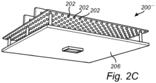
- Figs. 2A - 2C conceptually illustrating the controllable illumination assembly to be used in relation to the imaging device 102, also forming part of the optical inspection system 100.
- the illumination assembly 200 comprises a plurality of light emitting diodes (LEDs) 202 arranged to surround the image sensor 204 comprised with the imaging device 102.
- the LEDs are arranged in a matrix formation (dashed lines) surrounding the image sensor 204.
- the image sensor 204 is conceptually shown without an optical lens to be used together with the image sensor 204 in capturing images/video sequences of the object.
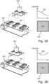
- the alternative illumination assembly 200' corresponds in function and form to the illumination assembly 200 as shown in Fig. 2A .
- the LEDs 202 are in this embodiment rather arranged in a circular (dashed lines) formation surrounding the image sensor 204. It may of course be possible to arrange the LEDs 202 differently, as compared to what is shown in any of Figs. 2A and 2B .
- a further alternative illumination assembly 200" is optionally provided with an optical diffuser member 206.
- the optical diffuser member 206 is placed adjacent to the LEDs 202, between the LEDs 202 and the object 104 to be illuminated.
- the optical diffuser member 206 may be used for "spreading" light emitted from the individual LEDs 202, thereby providing a more homogeneous beam of light as seen from the further alternative illumination assembly 200".
- such an implementation may be advantageous for improving the homogenous illumination of the object.
- FIG. 3A illustrating exemplary operations of the optical inspection system 100 when the imaging device 102 is dynamically repositioned in relation to the object 104.
- the imaging device 102 is shows to be positioned somewhat to the left of the object (as seen from a center of the object) in a direction of the conveyor 106.
- the illumination assembly 200 or equally 200'/200
- FIG. 3A show as a somewhat directional light, whereby an intensity level 302 as seen in relation to the illumination assembly 200 is allowed to be in comparison higher on the left hand side of the illumination assembly 200 as compared to the right hand side.
- individual control parameters for the LEDs of the illumination assembly 200 will control the LEDs 200 accordingly.
- FIG. 3B another example of position of the imaging device 102 in relation to the object 104 is presented. Specifically, in Fig. 3B the imaging device 102 is shows as being essentially above the object 104, thus essentially in line with the center of the object 104. In such a scenario it may for example (possibly dependent on the type of object) be possible to allow the illumination assembly 200 to illuminate the object using an alternative intensity level 304, whereby the intensity level for the LEDs 202 at the center of the illumination assembly 200 is decreased as compared to the LEDs 202 at the "edges" of the illumination assembly 200. As above, the individual control parameters for the LEDs of the illumination assembly 200 will control the LEDs 200 accordingly.
- the intensity levels 302, 304 provided in relation to Fig. 3A and 3B are exemplary, and may be formed differently, for example dependent on the type of object to be inspected, an external structure of the object, etc., as discussed above. Accordingly, in some embodiments e.g. the intensity level such as shown in Fig. 3A may be the opposite way around (i.e. higher towards the center of the object).
- the present disclosure relates an optical vision system 100 for automated inspection of an object 104 as well as to a method for operating such an optical vision system 100.
- the illumination assembly 200, 200', 200" is controlled, S1, to illuminate the object 104 with a predetermined illumination pattern based on a selected object type.
- the imaging device 102 will then acquire, S2, a first image or video sequence of the object 104.
- the control unit 108 comprised with the optical vision system 100 will then determine, S3, an illumination quality metric based on the acquired first image.
- the illumination quality metric is preferable adapted to determine a homogeneity of illumination at the object 104.
- the control unit 108 will determine if the illumination quality metric is below or above a predetermined threshold. In case the illumination quality metric is below the predetermined threshold, then the control unit 108 determines, S4, an adapted illumination pattern based on the illumination quality metric. In a possible embodiment the illumination pattern is adjusted dependent on a result of the determination of the homogeneity of illumination at the object 104. That is, the result of homogeneity calculation may be taken into account when determining the adapted illumination pattern. The control unit 108 will then individually control, S5, the LEDs 202 to illuminate the object 104 with the adapted illumination pattern.
- Advantages with the present disclosure includes the possibility of providing adequate illumination for different types of e.g. objects using the same type of illumination assembly, allowing an illumination pattern formed by such an illumination assembly may be adapted to match the object type.
- the present disclosure contemplates methods, systems and program products on any machine-readable media for accomplishing various operations.
- the embodiments of the present disclosure may be implemented using existing computer processors, or by a special purpose computer processor for an appropriate system, incorporated for this or another purpose, or by a hardwired system.
- Embodiments within the scope of the present disclosure include program products comprising machine-readable media for carrying or having machine-executable instructions or data structures stored thereon.
- Such machine-readable media can be any available media that can be accessed by a general purpose or special purpose computer or other machine with a processor.
- machine-readable media can comprise RAM, ROM, EPROM, EEPROM, CD-ROM or other optical disk storage, magnetic disk storage or other magnetic storage devices, or any other medium which can be used to carry or store desired program code in the form of machine-executable instructions or data structures and which can be accessed by a general purpose or special purpose computer or other machine with a processor.
- a network or another communications connection either hardwired, wireless, or a combination of hardwired or wireless
- any such connection is properly termed a machine-readable medium.
- Machine-executable instructions include, for example, instructions and data that cause a general-purpose computer, special purpose computer, or special purpose processing machines to perform a certain function or group of functions.
Landscapes
- Physics & Mathematics (AREA)
- General Physics & Mathematics (AREA)
- Engineering & Computer Science (AREA)
- General Health & Medical Sciences (AREA)
- Pathology (AREA)
- Health & Medical Sciences (AREA)
- Life Sciences & Earth Sciences (AREA)
- Chemical & Material Sciences (AREA)
- Analytical Chemistry (AREA)
- Biochemistry (AREA)
- Immunology (AREA)
- Quality & Reliability (AREA)
- Computer Vision & Pattern Recognition (AREA)
- Theoretical Computer Science (AREA)
- Textile Engineering (AREA)
- Multimedia (AREA)
- Signal Processing (AREA)
- Investigating Materials By The Use Of Optical Means Adapted For Particular Applications (AREA)
- Microscoopes, Condenser (AREA)
- Instruments For Viewing The Inside Of Hollow Bodies (AREA)
Claims (15)
- Optisches Bildverarbeitungssystem (100) zur automatisierten Inspektion eines Objektes (104), wobei das System Folgendes umfasst:- eine Bildgebungsvorrichtung (102), wobei die Bildgebungsvorrichtung Folgendes umfasst:- einen Bildsensor (204), der zum Aufnehmen eines Bildes des Objektes konfiguriert ist; und- eine steuerbare Beleuchtungsbaugruppe (200, 200', 200''), die zum Beleuchten des Objektes konfiguriert ist, wobei die Beleuchtungsbaugruppe mehrere individuell steuerbare Lichtquellen (202) umfasst, die derart positioniert sind, dass sie den Bildsensor umgeben, und- eine Steuereinheit (108) in elektrischer Kommunikation mit und konfiguriert zum Betreiben der Bildgebungsvorrichtung,wobei die Steuereinheit konfiguriert ist, Folgendes automatisch durchzuführen:- Steuern der Beleuchtungsbaugruppe zum Beleuchten des Objektes mit einem vorbestimmten Beleuchtungsmuster basierend auf einem ausgewählten Objekttyp;- Erfassen eines ersten Bildes des Objektes unter Verwendung des Bildsensors;- Bestimmen einer Beleuchtungsqualitätsmetrik basierend auf dem ersten Bild;- Bestimmen, wenn die Bestimmung der Beleuchtungsqualitätsmetrik angibt, dass die Beleuchtungsqualitätsmetrik unter einer vorbestimmten Schwelle liegt, eines angepassten Beleuchtungsmusters basierend auf der Beleuchtungsqualitätsmetrik, und- Steuern der Beleuchtungsbaugruppe zum Beleuchten des Objektes mit dem angepassten Beleuchtungsmuster,wobei die Steuereinheit (108) ferner zu Folgendem konfiguriert ist:- dynamisches Umpositionieren der Bildgebungsvorrichtung in Bezug auf das Objekt, und- Anpassen des Beleuchtungsmusters gemäß der Bestimmung des angepassten Beleuchtungsmusters, welches auch basierend auf einer relativen Position der Bildgebungsvorrichtung in Bezug auf das Objekt bestimmt wird.
- Optisches Bildverarbeitungssystem nach Anspruch 1, wobei das Bestimmen der Bildqualitätsmetrik das Bestimmen eines Grades der homogenen Lichtverteilung über ein ausgewähltes Sichtfeld innerhalb des aufgenommenen Bildes umfasst.
- Optisches Bildverarbeitungssystem nach einem der Ansprüche 1 und 2, wobei das Bestimmen des angepassten Beleuchtungsmusters das Bestimmen eines Grades der Übereinstimmung mit dem Lambertschen Kosinusgesetz in Bezug auf das Objekt und das durch die Beleuchtungsbaugruppe bereitgestellte Licht umfasst.
- Optisches Bildverarbeitungssystem nach Anspruch 3, wobei die Steuereinheit ferner zum Optimieren des Grades der Übereinstimmung mit dem Lambertschen Kosinusgesetz in Bezug auf das Objekt und das durch die Beleuchtungsbaugruppe bereitgestellte Licht konfiguriert ist.
- Optisches Bildverarbeitungssystem nach einem der vorhergehenden Ansprüche, wobei das Bestimmen des angepassten Beleuchtungsmusters das Bestimmen eines Grades der Übereinstimmung mit dem Abstandsgesetz in Bezug auf das Objekt und das durch die Beleuchtungsbaugruppe bereitgestellte Licht umfasst.
- Optisches Bildverarbeitungssystem nach Anspruch 5, wobei die Steuereinheit ferner zum Optimieren des Grades der Übereinstimmung mit dem Abstandsgesetz in Bezug auf das Objekt und das durch die Beleuchtungsbaugruppe bereitgestellte Licht konfiguriert ist.
- Optisches Bildverarbeitungssystem nach einem der vorhergehenden Ansprüche, wobei jede Lichtquelle der Beleuchtungsbaugruppe mindestens eine Leuchtdiode umfasst.
- Optisches Bildverarbeitungssystem nach Anspruch 7, wobei jede Leuchtdiode eine optische Linse umfasst.
- Optisches Bildverarbeitungssystem nach einem der vorhergehenden Ansprüche, wobei die Steuereinheit ferner zu Folgendem konfiguriert ist:- Erfassen eines zweiten Bildes des Objektes unter Verwendung des Bildsensors, und- Bestimmen eines Inspektionsparameters für das Objekt.
- Optisches Bildverarbeitungssystem nach einem der vorhergehenden Ansprüche, wobei das vorbestimmte Beleuchtungsmuster Steuerparameter zum individuellen Steuern der mehreren Lichtquellen der Beleuchtungsbaugruppe umfasst.
- Optisches Bildverarbeitungssystem nach Anspruch 10, wobei die Steuerparameter zum individuellen Steuern der mehreren Lichtquellen der Beleuchtungsbaugruppe für den spezifischen Typ des zu inspizierenden Objektes vorab simuliert werden.
- Verfahren zum Betrieb eines optischen Bildverarbeitungssystems (100) zur automatisierten Inspektion eines Objektes (104), wobei das System Folgendes umfasst:- eine Bildgebungsvorrichtung (102), wobei die Bildgebungsvorrichtung Folgendes umfasst:- einen Bildsensor (204), der zum Aufnehmen eines Bildes des Objektes konfiguriert ist; und- eine steuerbare Beleuchtungsbaugruppe (200, 200', 200''), die zum Beleuchten des Objektes konfiguriert ist, wobei die Beleuchtungsbaugruppe mehrere individuell steuerbare Lichtquellen (202) umfasst, die derart positioniert sind, dass sie den Bildsensor umgeben, und- eine Steuereinheit (108) in elektrischer Kommunikation mit und konfiguriert zum Betreiben der Bildgebungsvorrichtung,wobei das Verfahren folgende Schritte umfasst:- Steuern der Beleuchtungsbaugruppe zum Beleuchten des Objektes mit einem vorbestimmten Beleuchtungsmuster basierend auf einem ausgewählten Objekttyp;- Erfassen eines ersten Bildes des Objektes unter Verwendung des Bildsensors;- Bestimmen einer Beleuchtungsqualitätsmetrik basierend auf dem ersten Bild;- Bestimmen, wenn die Bestimmung der Beleuchtungsqualitätsmetrik angibt, dass die Beleuchtungsqualitätsmetrik unter einer vorbestimmten Schwelle liegt, eines angepassten Beleuchtungsmusters basierend auf der Beleuchtungsqualitätsmetrik, und- Steuern der Beleuchtungsbaugruppe zum Beleuchten des Objektes mit dem angepassten Beleuchtungsmuster,wobei das Verfahren ferner Folgende Schritte umfasst:- dynamisches Umpositionieren, unter Verwendung der Steuereinheit, der Bildgebungsvorrichtung in Bezug auf das Objekt, und- Anpassen, unter Verwendung der Steuereinheit, des Beleuchtungsmusters gemäß der Bestimmung des angepassten Beleuchtungsmusters, welches auch basierend auf einer relativen Position der Bildgebungsvorrichtung in Bezug auf das Objekt bestimmt wird.
- Verfahren nach Anspruch 12, wobei das Bestimmen der Bildqualitätsmetrik das Bestimmen eines Grades der homogenen Lichtverteilung über ein ausgewähltes Sichtfeld innerhalb des aufgenommenen Bildes umfasst.
- Verfahren nach Anspruch 12, wobei das Verfahren, vor dem Steuern der Beleuchtungsbaugruppe zum Beleuchten des Objektes mit dem vorbestimmten Beleuchtungsmuster, Folgendes umfasst:- Simulieren eines Beleuchtungsmusters zur Beleuchtung des Objektes;- Optimieren, in der Simulation, des Beleuchtungsmusters zum Maximieren eines Grades der homogenen Lichtverteilung des Objektes, und- Auswählen des vorbestimmten Beleuchtungsmusters.
- Computerprogrammprodukt, welches ein nichttransitorisches computerlesbares Medium mit darauf gespeicherten Computerprogrammmitteln zum Betrieb eines optischen Bildverarbeitungssystems (100) zur automatisierten Inspektion eines Objektes (104) umfasst, wobei das System Folgendes umfasst:- eine Bildgebungsvorrichtung (102), wobei die Bildgebungsvorrichtung Folgendes umfasst:- einen Bildsensor (204), der zum Aufnehmen eines Bildes des Objektes konfiguriert ist; und- eine steuerbare Beleuchtungsbaugruppe (200, 200', 200''), die zum Beleuchten des Objektes konfiguriert ist, wobei die Beleuchtungsbaugruppe mehrere individuell steuerbare Lichtquellen (202) umfasst, die derart positioniert sind, dass sie den Bildsensor umgeben, und- eine Steuereinheit (108) in elektrischer Kommunikation mit und konfiguriert zum Betreiben des Bildsensors und der Beleuchtungsbaugruppe,wobei das Computerprogrammprodukt Folgendes umfasst:- Code zum Steuern der Beleuchtungsbaugruppe zum Beleuchten des Objektes mit einem vorbestimmten Beleuchtungsmuster basierend auf einem ausgewählten Objekttyp;- Code zum Erfassen eines ersten Bildes des Objektes unter Verwendung des Bildsensors;- Code zum Bestimmen einer Beleuchtungsqualitätsmetrik basierend auf dem ersten Bild;- Code zum Bestimmen, wenn die Bestimmung der Beleuchtungsqualitätsmetrik angibt, dass die Beleuchtungsqualitätsmetrik unter einer vorbestimmten Schwelle liegt, eines angepassten Beleuchtungsmusters basierend auf der Beleuchtungsqualitätsmetrik, und- Code zum Steuern der Beleuchtungsbaugruppe zum Beleuchten des Objektes mit dem angepassten Beleuchtungsmuster,wobei das Computerprogrammprodukt ferner Folgendes umfasst:- Code zum dynamischen Umpositionieren, unter Verwendung der Steuereinheit, der Bildgebungsvorrichtung in Bezug auf das Objekt, und- Code zum Anpassen, unter Verwendung der Steuereinheit, des Beleuchtungsmusters gemäß der Bestimmung des angepassten Beleuchtungsmusters, welches auch basierend auf einer relativen Position der Bildgebungsvorrichtung in Bezug auf das Objekt bestimmt wird.
Applications Claiming Priority (2)
| Application Number | Priority Date | Filing Date | Title |
|---|---|---|---|
| SE1751327A SE541493C2 (en) | 2017-10-26 | 2017-10-26 | System and method for optical inspection of an object |
| PCT/SE2018/051068 WO2019083429A1 (en) | 2017-10-26 | 2018-10-19 | SYSTEM AND METHOD FOR OPTICAL INSPECTION OF AN OBJECT |
Publications (4)
| Publication Number | Publication Date |
|---|---|
| EP3701330A1 EP3701330A1 (de) | 2020-09-02 |
| EP3701330A4 EP3701330A4 (de) | 2021-06-16 |
| EP3701330C0 EP3701330C0 (de) | 2024-01-03 |
| EP3701330B1 true EP3701330B1 (de) | 2024-01-03 |
Family
ID=66246645
Family Applications (1)
| Application Number | Title | Priority Date | Filing Date |
|---|---|---|---|
| EP18871284.8A Active EP3701330B1 (de) | 2017-10-26 | 2018-10-19 | System und verfahren zur optischen inspektion eines objekts |
Country Status (5)
| Country | Link |
|---|---|
| US (1) | US11385184B2 (de) |
| EP (1) | EP3701330B1 (de) |
| CN (1) | CN111263914A (de) |
| SE (1) | SE541493C2 (de) |
| WO (1) | WO2019083429A1 (de) |
Families Citing this family (7)
| Publication number | Priority date | Publication date | Assignee | Title |
|---|---|---|---|---|
| KR102685226B1 (ko) * | 2017-08-28 | 2024-07-16 | 트리나미엑스 게엠베하 | 적어도 하나의 기하학적 정보를 판정하기 위한 측거기 |
| IT201900005536A1 (it) * | 2019-04-10 | 2020-10-10 | Doss Visual Solution S R L | Metodo di acquisizione immagini per una macchina di ispezione ottica |
| JP2022054938A (ja) * | 2020-09-28 | 2022-04-07 | 株式会社リコー | 検査装置、検査システム、検査方法 |
| CN113155845A (zh) * | 2021-04-09 | 2021-07-23 | 武汉精测电子集团股份有限公司 | 一种光源及其设置方法、光学检测方法及系统 |
| US12462228B2 (en) * | 2021-11-01 | 2025-11-04 | Green Panda Holdings Limited | Wireless communication device assessment system |
| US12247829B2 (en) * | 2023-01-31 | 2025-03-11 | Lawrence Livermore National Security, Llc | Optimal parameter selection for structured light metrology |
| US12549861B2 (en) * | 2023-05-15 | 2026-02-10 | General Electric Company | Part surface inspection and illumination system |
Family Cites Families (10)
| Publication number | Priority date | Publication date | Assignee | Title |
|---|---|---|---|---|
| DE29807926U1 (de) * | 1998-05-02 | 1999-09-09 | ibea Ingenieurbüro für Elektronik und Automation GmbH, 22525 Hamburg | Vorrichtung zur optischen Prüfung der Oberflächenbeschaffenheit von Gegenständen |
| US6850637B1 (en) * | 2000-06-28 | 2005-02-01 | Teradyne, Inc. | Lighting arrangement for automated optical inspection system |
| US6627863B2 (en) | 2000-12-15 | 2003-09-30 | Mitutoyo Corporation | System and methods to determine the settings of multiple light sources in a vision system |
| US7256833B2 (en) * | 2002-05-22 | 2007-08-14 | Avago Technologies Ecbu Ip (Singapore) Pte. Ltd. | Method and apparatus for automatically optimizing optical contrast in automated equipment |
| TWI377428B (en) * | 2008-10-20 | 2012-11-21 | Asia Optical Co Inc | Image capture apparatus with charged capacitor switching device for photoflash and switching method therefor |
| US10498933B2 (en) | 2011-11-22 | 2019-12-03 | Cognex Corporation | Camera system with exchangeable illumination assembly |
| JP5874398B2 (ja) * | 2012-01-05 | 2016-03-02 | オムロン株式会社 | 画像検査装置の検査領域設定方法 |
| TW201421183A (zh) | 2012-11-28 | 2014-06-01 | Univ Nat Taiwan Science Tech | 最佳視覺照明裝置及方法 |
| JP6373577B2 (ja) * | 2013-12-25 | 2018-08-15 | ザインエレクトロニクス株式会社 | 撮像制御装置 |
| WO2017080875A1 (en) * | 2015-11-10 | 2017-05-18 | Koninklijke Philips N.V. | Adaptive light source |
-
2017
- 2017-10-26 SE SE1751327A patent/SE541493C2/en unknown
-
2018
- 2018-10-19 EP EP18871284.8A patent/EP3701330B1/de active Active
- 2018-10-19 US US16/758,269 patent/US11385184B2/en active Active
- 2018-10-19 WO PCT/SE2018/051068 patent/WO2019083429A1/en not_active Ceased
- 2018-10-19 CN CN201880068983.9A patent/CN111263914A/zh active Pending
Also Published As
| Publication number | Publication date |
|---|---|
| EP3701330A4 (de) | 2021-06-16 |
| WO2019083429A1 (en) | 2019-05-02 |
| EP3701330C0 (de) | 2024-01-03 |
| US11385184B2 (en) | 2022-07-12 |
| CN111263914A (zh) | 2020-06-09 |
| SE1751327A1 (en) | 2019-04-27 |
| US20200340929A1 (en) | 2020-10-29 |
| SE541493C2 (en) | 2019-10-15 |
| EP3701330A1 (de) | 2020-09-02 |
Similar Documents
| Publication | Publication Date | Title |
|---|---|---|
| EP3701330B1 (de) | System und verfahren zur optischen inspektion eines objekts | |
| US10304176B2 (en) | Image inspection device | |
| US10416086B2 (en) | Image inspection device | |
| US8363929B2 (en) | Shape measurement apparatus and calibration method | |
| CN105122943B (zh) | 特性化光源和移动设备的方法 | |
| JP6362050B2 (ja) | 撮影装置、照明制御装置および照明制御方法 | |
| KR20190082111A (ko) | 적응적 확산 조명 시스템들 및 방법들 | |
| KR101878654B1 (ko) | 광 조사 장치 및 방법 | |
| JP6601264B2 (ja) | 照明条件設定装置、照明条件設定方法及び照明条件設定用コンピュータプログラム | |
| KR101361537B1 (ko) | 적외선패턴조사부를 구비하는 비전검사장치 | |
| CN110599450B (zh) | Led光源位置校正方法及系统 | |
| CN110100173A (zh) | 用于检测宝石中包含物的系统和方法 | |
| JP2018189558A (ja) | 画像検査装置 | |
| CN106599929B (zh) | 虚拟现实特征点筛选空间定位方法 | |
| US10616540B2 (en) | Lamp control | |
| US9448115B2 (en) | Apparatus and methods for extracting topographic information from inspected objects | |
| CN104809423B (zh) | 条形码识读设备 | |
| CN109414120B (zh) | 用于提供语义信息的装置以及操作其的方法 | |
| US9593825B2 (en) | Illumination system | |
| CN108885181A (zh) | 用于通过多方向照射检测表面上的缺陷的方法和相关装置 | |
| TWI889611B (zh) | 種蛋照蛋汰除裝置 | |
| US20220232155A1 (en) | Image processing device and image processing program | |
| WO2017029528A1 (en) | Framing-light projection | |
| JP2019109070A (ja) | 画像処理システム、画像処理プログラム、および画像処理方法 | |
| CN103443613A (zh) | 用于确定表面的反射率的方法和装置 |
Legal Events
| Date | Code | Title | Description |
|---|---|---|---|
| STAA | Information on the status of an ep patent application or granted ep patent |
Free format text: STATUS: THE INTERNATIONAL PUBLICATION HAS BEEN MADE |
|
| PUAI | Public reference made under article 153(3) epc to a published international application that has entered the european phase |
Free format text: ORIGINAL CODE: 0009012 |
|
| STAA | Information on the status of an ep patent application or granted ep patent |
Free format text: STATUS: REQUEST FOR EXAMINATION WAS MADE |
|
| 17P | Request for examination filed |
Effective date: 20200424 |
|
| AK | Designated contracting states |
Kind code of ref document: A1 Designated state(s): AL AT BE BG CH CY CZ DE DK EE ES FI FR GB GR HR HU IE IS IT LI LT LU LV MC MK MT NL NO PL PT RO RS SE SI SK SM TR |
|
| AX | Request for extension of the european patent |
Extension state: BA ME |
|
| DAV | Request for validation of the european patent (deleted) | ||
| DAX | Request for extension of the european patent (deleted) | ||
| A4 | Supplementary search report drawn up and despatched |
Effective date: 20210514 |
|
| RIC1 | Information provided on ipc code assigned before grant |
Ipc: G03B 15/05 20210101AFI20210508BHEP Ipc: G01N 21/88 20060101ALI20210508BHEP Ipc: G01N 21/84 20060101ALI20210508BHEP Ipc: G03B 15/03 20210101ALI20210508BHEP |
|
| GRAP | Despatch of communication of intention to grant a patent |
Free format text: ORIGINAL CODE: EPIDOSNIGR1 |
|
| STAA | Information on the status of an ep patent application or granted ep patent |
Free format text: STATUS: GRANT OF PATENT IS INTENDED |
|
| INTG | Intention to grant announced |
Effective date: 20230822 |
|
| GRAS | Grant fee paid |
Free format text: ORIGINAL CODE: EPIDOSNIGR3 |
|
| GRAA | (expected) grant |
Free format text: ORIGINAL CODE: 0009210 |
|
| STAA | Information on the status of an ep patent application or granted ep patent |
Free format text: STATUS: THE PATENT HAS BEEN GRANTED |
|
| AK | Designated contracting states |
Kind code of ref document: B1 Designated state(s): AL AT BE BG CH CY CZ DE DK EE ES FI FR GB GR HR HU IE IS IT LI LT LU LV MC MK MT NL NO PL PT RO RS SE SI SK SM TR |
|
| REG | Reference to a national code |
Ref country code: GB Ref legal event code: FG4D |
|
| REG | Reference to a national code |
Ref country code: CH Ref legal event code: EP |
|
| REG | Reference to a national code |
Ref country code: DE Ref legal event code: R096 Ref document number: 602018063751 Country of ref document: DE |
|
| REG | Reference to a national code |
Ref country code: IE Ref legal event code: FG4D |
|
| U01 | Request for unitary effect filed |
Effective date: 20240108 |
|
| U07 | Unitary effect registered |
Designated state(s): AT BE BG DE DK EE FI FR IT LT LU LV MT NL PT SE SI Effective date: 20240115 |
|
| PG25 | Lapsed in a contracting state [announced via postgrant information from national office to epo] |
Ref country code: ES Free format text: LAPSE BECAUSE OF FAILURE TO SUBMIT A TRANSLATION OF THE DESCRIPTION OR TO PAY THE FEE WITHIN THE PRESCRIBED TIME-LIMIT Effective date: 20240103 |
|
| PG25 | Lapsed in a contracting state [announced via postgrant information from national office to epo] |
Ref country code: ES Free format text: LAPSE BECAUSE OF FAILURE TO SUBMIT A TRANSLATION OF THE DESCRIPTION OR TO PAY THE FEE WITHIN THE PRESCRIBED TIME-LIMIT Effective date: 20240103 |
|
| PG25 | Lapsed in a contracting state [announced via postgrant information from national office to epo] |
Ref country code: IS Free format text: LAPSE BECAUSE OF FAILURE TO SUBMIT A TRANSLATION OF THE DESCRIPTION OR TO PAY THE FEE WITHIN THE PRESCRIBED TIME-LIMIT Effective date: 20240503 |
|
| PG25 | Lapsed in a contracting state [announced via postgrant information from national office to epo] |
Ref country code: GR Free format text: LAPSE BECAUSE OF FAILURE TO SUBMIT A TRANSLATION OF THE DESCRIPTION OR TO PAY THE FEE WITHIN THE PRESCRIBED TIME-LIMIT Effective date: 20240404 |
|
| PG25 | Lapsed in a contracting state [announced via postgrant information from national office to epo] |
Ref country code: RS Free format text: LAPSE BECAUSE OF FAILURE TO SUBMIT A TRANSLATION OF THE DESCRIPTION OR TO PAY THE FEE WITHIN THE PRESCRIBED TIME-LIMIT Effective date: 20240403 Ref country code: HR Free format text: LAPSE BECAUSE OF FAILURE TO SUBMIT A TRANSLATION OF THE DESCRIPTION OR TO PAY THE FEE WITHIN THE PRESCRIBED TIME-LIMIT Effective date: 20240103 |
|
| PG25 | Lapsed in a contracting state [announced via postgrant information from national office to epo] |
Ref country code: CZ Free format text: LAPSE BECAUSE OF FAILURE TO SUBMIT A TRANSLATION OF THE DESCRIPTION OR TO PAY THE FEE WITHIN THE PRESCRIBED TIME-LIMIT Effective date: 20240103 |
|
| PG25 | Lapsed in a contracting state [announced via postgrant information from national office to epo] |
Ref country code: RS Free format text: LAPSE BECAUSE OF FAILURE TO SUBMIT A TRANSLATION OF THE DESCRIPTION OR TO PAY THE FEE WITHIN THE PRESCRIBED TIME-LIMIT Effective date: 20240403 Ref country code: IS Free format text: LAPSE BECAUSE OF FAILURE TO SUBMIT A TRANSLATION OF THE DESCRIPTION OR TO PAY THE FEE WITHIN THE PRESCRIBED TIME-LIMIT Effective date: 20240503 Ref country code: HR Free format text: LAPSE BECAUSE OF FAILURE TO SUBMIT A TRANSLATION OF THE DESCRIPTION OR TO PAY THE FEE WITHIN THE PRESCRIBED TIME-LIMIT Effective date: 20240103 Ref country code: GR Free format text: LAPSE BECAUSE OF FAILURE TO SUBMIT A TRANSLATION OF THE DESCRIPTION OR TO PAY THE FEE WITHIN THE PRESCRIBED TIME-LIMIT Effective date: 20240404 Ref country code: CZ Free format text: LAPSE BECAUSE OF FAILURE TO SUBMIT A TRANSLATION OF THE DESCRIPTION OR TO PAY THE FEE WITHIN THE PRESCRIBED TIME-LIMIT Effective date: 20240103 |
|
| PG25 | Lapsed in a contracting state [announced via postgrant information from national office to epo] |
Ref country code: PL Free format text: LAPSE BECAUSE OF FAILURE TO SUBMIT A TRANSLATION OF THE DESCRIPTION OR TO PAY THE FEE WITHIN THE PRESCRIBED TIME-LIMIT Effective date: 20240103 |
|
| PG25 | Lapsed in a contracting state [announced via postgrant information from national office to epo] |
Ref country code: PL Free format text: LAPSE BECAUSE OF FAILURE TO SUBMIT A TRANSLATION OF THE DESCRIPTION OR TO PAY THE FEE WITHIN THE PRESCRIBED TIME-LIMIT Effective date: 20240103 |
|
| REG | Reference to a national code |
Ref country code: DE Ref legal event code: R097 Ref document number: 602018063751 Country of ref document: DE |
|
| PG25 | Lapsed in a contracting state [announced via postgrant information from national office to epo] |
Ref country code: SM Free format text: LAPSE BECAUSE OF FAILURE TO SUBMIT A TRANSLATION OF THE DESCRIPTION OR TO PAY THE FEE WITHIN THE PRESCRIBED TIME-LIMIT Effective date: 20240103 |
|
| PG25 | Lapsed in a contracting state [announced via postgrant information from national office to epo] |
Ref country code: SK Free format text: LAPSE BECAUSE OF FAILURE TO SUBMIT A TRANSLATION OF THE DESCRIPTION OR TO PAY THE FEE WITHIN THE PRESCRIBED TIME-LIMIT Effective date: 20240103 |
|
| PG25 | Lapsed in a contracting state [announced via postgrant information from national office to epo] |
Ref country code: SM Free format text: LAPSE BECAUSE OF FAILURE TO SUBMIT A TRANSLATION OF THE DESCRIPTION OR TO PAY THE FEE WITHIN THE PRESCRIBED TIME-LIMIT Effective date: 20240103 Ref country code: SK Free format text: LAPSE BECAUSE OF FAILURE TO SUBMIT A TRANSLATION OF THE DESCRIPTION OR TO PAY THE FEE WITHIN THE PRESCRIBED TIME-LIMIT Effective date: 20240103 Ref country code: RO Free format text: LAPSE BECAUSE OF FAILURE TO SUBMIT A TRANSLATION OF THE DESCRIPTION OR TO PAY THE FEE WITHIN THE PRESCRIBED TIME-LIMIT Effective date: 20240103 |
|
| PLBE | No opposition filed within time limit |
Free format text: ORIGINAL CODE: 0009261 |
|
| STAA | Information on the status of an ep patent application or granted ep patent |
Free format text: STATUS: NO OPPOSITION FILED WITHIN TIME LIMIT |
|
| U20 | Renewal fee for the european patent with unitary effect paid |
Year of fee payment: 7 Effective date: 20241015 |
|
| 26N | No opposition filed |
Effective date: 20241007 |
|
| REG | Reference to a national code |
Ref country code: CH Ref legal event code: PL |
|
| PG25 | Lapsed in a contracting state [announced via postgrant information from national office to epo] |
Ref country code: MC Free format text: LAPSE BECAUSE OF FAILURE TO SUBMIT A TRANSLATION OF THE DESCRIPTION OR TO PAY THE FEE WITHIN THE PRESCRIBED TIME-LIMIT Effective date: 20240103 |
|
| PG25 | Lapsed in a contracting state [announced via postgrant information from national office to epo] |
Ref country code: CH Free format text: LAPSE BECAUSE OF NON-PAYMENT OF DUE FEES Effective date: 20241031 |
|
| PG25 | Lapsed in a contracting state [announced via postgrant information from national office to epo] |
Ref country code: IE Free format text: LAPSE BECAUSE OF NON-PAYMENT OF DUE FEES Effective date: 20241019 |
|
| U20 | Renewal fee for the european patent with unitary effect paid |
Year of fee payment: 8 Effective date: 20251016 |
|
| PGFP | Annual fee paid to national office [announced via postgrant information from national office to epo] |
Ref country code: GB Payment date: 20251020 Year of fee payment: 8 |
|
| PGFP | Annual fee paid to national office [announced via postgrant information from national office to epo] |
Ref country code: NO Payment date: 20251023 Year of fee payment: 8 |
|
| PG25 | Lapsed in a contracting state [announced via postgrant information from national office to epo] |
Ref country code: CY Free format text: LAPSE BECAUSE OF FAILURE TO SUBMIT A TRANSLATION OF THE DESCRIPTION OR TO PAY THE FEE WITHIN THE PRESCRIBED TIME-LIMIT; INVALID AB INITIO Effective date: 20181019 |
|
| PG25 | Lapsed in a contracting state [announced via postgrant information from national office to epo] |
Ref country code: HU Free format text: LAPSE BECAUSE OF FAILURE TO SUBMIT A TRANSLATION OF THE DESCRIPTION OR TO PAY THE FEE WITHIN THE PRESCRIBED TIME-LIMIT; INVALID AB INITIO Effective date: 20181019 |