EP3701203B1 - Kühlelemente und diese enthaltende kühlanordnungen - Google Patents
Kühlelemente und diese enthaltende kühlanordnungen Download PDFInfo
- Publication number
- EP3701203B1 EP3701203B1 EP18793384.1A EP18793384A EP3701203B1 EP 3701203 B1 EP3701203 B1 EP 3701203B1 EP 18793384 A EP18793384 A EP 18793384A EP 3701203 B1 EP3701203 B1 EP 3701203B1
- Authority
- EP
- European Patent Office
- Prior art keywords
- heat
- cooling element
- heat sink
- cooling
- volume
- Prior art date
- Legal status (The legal status is an assumption and is not a legal conclusion. Google has not performed a legal analysis and makes no representation as to the accuracy of the status listed.)
- Active
Links
Images


Classifications
-
- C—CHEMISTRY; METALLURGY
- C09—DYES; PAINTS; POLISHES; NATURAL RESINS; ADHESIVES; COMPOSITIONS NOT OTHERWISE PROVIDED FOR; APPLICATIONS OF MATERIALS NOT OTHERWISE PROVIDED FOR
- C09K—MATERIALS FOR MISCELLANEOUS APPLICATIONS, NOT PROVIDED FOR ELSEWHERE
- C09K5/00—Heat-transfer, heat-exchange or heat-storage materials, e.g. refrigerants; Materials for the production of heat or cold by chemical reactions other than by combustion
- C09K5/02—Materials undergoing a change of physical state when used
- C09K5/06—Materials undergoing a change of physical state when used the change of state being from liquid to solid or vice versa
-
- A—HUMAN NECESSITIES
- A47—FURNITURE; DOMESTIC ARTICLES OR APPLIANCES; COFFEE MILLS; SPICE MILLS; SUCTION CLEANERS IN GENERAL
- A47J—KITCHEN EQUIPMENT; COFFEE MILLS; SPICE MILLS; APPARATUS FOR MAKING BEVERAGES
- A47J41/00—Thermally-insulated vessels, e.g. flasks, jugs, jars
- A47J41/0038—Thermally-insulated vessels, e.g. flasks, jugs, jars comprising additional heating or cooling means, i.e. use of thermal energy in addition to stored material
-
- B—PERFORMING OPERATIONS; TRANSPORTING
- B65—CONVEYING; PACKING; STORING; HANDLING THIN OR FILAMENTARY MATERIAL
- B65D—CONTAINERS FOR STORAGE OR TRANSPORT OF ARTICLES OR MATERIALS, e.g. BAGS, BARRELS, BOTTLES, BOXES, CANS, CARTONS, CRATES, DRUMS, JARS, TANKS, HOPPERS, FORWARDING CONTAINERS; ACCESSORIES, CLOSURES, OR FITTINGS THEREFOR; PACKAGING ELEMENTS; PACKAGES
- B65D81/00—Containers, packaging elements, or packages, for contents presenting particular transport or storage problems, or adapted to be used for non-packaging purposes after removal of contents
- B65D81/18—Containers, packaging elements, or packages, for contents presenting particular transport or storage problems, or adapted to be used for non-packaging purposes after removal of contents providing specific environment for contents, e.g. temperature above or below ambient
-
- F—MECHANICAL ENGINEERING; LIGHTING; HEATING; WEAPONS; BLASTING
- F25—REFRIGERATION OR COOLING; COMBINED HEATING AND REFRIGERATION SYSTEMS; HEAT PUMP SYSTEMS; MANUFACTURE OR STORAGE OF ICE; LIQUEFACTION SOLIDIFICATION OF GASES
- F25D—REFRIGERATORS; COLD ROOMS; ICE-BOXES; COOLING OR FREEZING APPARATUS NOT OTHERWISE PROVIDED FOR
- F25D3/00—Devices using other cold materials; Devices using cold-storage bodies
- F25D3/02—Devices using other cold materials; Devices using cold-storage bodies using ice, e.g. ice-boxes
- F25D3/06—Movable containers
- F25D3/08—Movable containers portable, i.e. adapted to be carried personally
Definitions
- This disclosure relates generally to cooling elements, and assemblies and containers comprising the cooling elements; particularly but not exclusively to portable cooling assemblies for cooling frozen or chilled items.
- EP 3 054 243 A1 discloses a beverage chiller including a first and second cylinders, each including a respective sidewall defined by respective inner and outer surfaces.
- the diameter of the second cylinder is less than a diameter of the first cylinder so as to fit within the first cylinder with the inner surface of the first cylinder confronting the outer surface of the second cylinder, to define a first reservoir between the first and second cylinders for receiving a beverage to be chilled.
- the second cylinder further defines a chamber for receiving a chilling medium.
- WO2006/123931A2 discloses a cooling element of the prior art.
- WO2008/072098A1 discloses a cooling element according to the preamble of claim 1.
- cooling elements and assemblies which may cool goods or maintain chilled or frozen goods in their chilled states.
- cooling or keeping cooled, chilled or frozen items such as consumable or perishable items, including, but not limited to food, drinks, pharmaceutical products, medical products, cosmetic products, healthcare products, and the like.
- the cooling elements and cooling assemblies may be environmentally friendly, and / or to be relatively simple to manufacture and use.
- a cooling element is provided as defined in claim 1.
- the cooling element of the invention is for cooling a body and is configured such that when the proximal side of the cooling element contacts a surface of the body in use, the heat conduction layer will conduct heat from the body and into the heat sink volume more rapidly than heat is conducted through the heat retardant layer and into the heat sink volume, from the distal side of the cooling element.
- a cooling assembly comprising one or more cooling element of the invention.
- a method of cooling a body including providing a cooling element according to the invention; reducing the temperature of the heat sink volume of the cooling element to less than the first temperature, and arranging the cooling element against a surface of the body, with the proximal side of the cooling element being in contact with the side surface of the body.
- the cooling element may be arranged within a cooling assembly according to the second aspect.
- the body to be cooled may be housed within a container, in which case the cooling element is suitably arranged between the body and a surface of the container housing the body.
- cooling is primarily intended to mean reducing the temperature of a body by a desired amount. However, in some embodiments, the term cooling may also mean retaining a previously cooled body at, or within, 5°C, preferably within 2°C, of that temperature.
- the cooling element may be sufficiently flexible to be capable of curving in a range of arcs, in response to being placed against a curved surface of the body.
- this may be achieved by the heat sink volume being formed of a plurality of heat sink elements, which may be arranged discontinuously alongside each other.
- the heat sink volume may comprise a plurality of elongate heat sink elements, arranged substantially parallel to each other (along their longitudinal axes); the heat sink elements may or may not contact each other.
- Such arrangements may permit the cooling element to be curved about an axis that is substantially parallel to the longitudinal axes of the heat sink elements, allowing the cooling element to be placed against curved surface, such as the side of a bottle or a beverage can, even when the first substance is frozen.
- the heat sink volume may comprise a plurality of heat sink elements arrange on supportive sheet, for example on the heat conduction layer or the heat retardant layer.
- the plurality of heat sink elements may be arranged in a geometric pattern, such as a series of polygonal shaped elements (for example, triangular, square, pentagonal, hexagonal or octagonal shaped elements) arranged in an regular array.
- the heat sink volume may comprise any number of heat sink elements according to the desired application.
- the heat sink volume may comprise at least about 2, or at least about 5, or at least about 10 heat sink elements
- the heat sink volume may comprise at most about 100, or at most about 50 heat sink elements.
- the heat sink volume may comprise from 2 to 100 heat sink elements, for example from 2 to 50 heat sink elements or from 5 to 15 heat sink elements.
- the heat sink volume may comprise a single heat sink element.
- the heat sink volume is the sum of the volumes of all the heat sink elements, in embodiments comprising a plurality of heat sink elements.
- the heat sink volume is sufficient to reduce the temperature of the body from an initial temperature to a desired temperature within a desired time period.
- the desired time period is around 10 minutes, or around 20 minutes or around 30 minutes.
- the desired time period may be from around 10 minutes to around 30 minutes.
- the initial temperature and the desired temperature will depend upon the particular application and the body to be cooled or retained chilled.
- the initial temperature may be around 15°C, around 20°C, around 25°C, around 30°C or around 40°C.
- the desired temperature may be around 30 °C , around 20°C, around 15°C, around 10°C, or around 5°C.
- the first substance of the heat sink volume may be frozen.
- the first substance of the heat sink volume may be partially frozen.
- the body to be cooled may be a fluid or solid material, or a mixture thereof. If the body is a fluid, it is preferably contained in any suitable vessel or container. A body comprising a solid material may be contained in a vessel or container or need not be.
- the heat sink volume may be determined based on a volume of the body to be cooled, and the amount of heat that is desired to be removed. While not wishing to be bound by a particular theory, the greater the heat sink volume, the greater the maximum quantity of heat that may be expected to be absorbed by the heat sink volume (all else being equal). It is expected that the greater the heat sink volume, the greater the volume of the body that can be cooled; and / or the more rapidly the body may be cooled; and / or the greater the temperature by which the body may be reduced.
- the heat sink volume and the heat conduction layer may be configured and arranged such that the area of the proximal boundary between them is sufficiently great such that a desired quantity of heat can be conducted from the body to the heat sink volume within a desired period of time.
- the area of the proximal boundary is the total combined area of all the proximal boundaries between all the respective heat sink elements and the heat conduction layer. While not wishing to be bound by a particular theory, the greater the area of the proximal boundary, the more rapidly heat is expected to be transferred from the heat conduction layer to the heat sink volume (all else being equal). The area of the proximal boundary may be expected to limit the rate of heat conduction from the heat conduction layer to the heat sink volume.
- the heat conduction layer is a sheet material.
- the heat retardant layer may comprise a sheet material.
- the heat conduction layer and the heat retardant layer each comprise or consist of a sheet, in which the heat conduction layer is attached to a proximal side of the heat sink element by means of adhesive material and the heat retardant layer is attached to a distal side of the heat sink element by means of adhesive material.
- the heat sink volume comprises or consists of one or more heat sink elements
- the heat conduction layer and the heat retardant layer each comprise or consist of a sheet
- the heat conduction layer is attached to respective proximal sides of each of a plurality of heat sink elements by means of adhesive material
- the heat retardant layer is attached to respective distal sides of each of a plurality of heat sink elements by means of adhesive material.
- the heat sink element or elements may be said to be sandwiched between the heat conduction layer and the heat retardant layer.
- the first temperature is less than 20°C, for example, less than 18°C, less than 15°C.
- the first temperature may be as low as 0°C.
- the first substance may comprise water in the liquid state, when at a temperature greater than the first temperature, or the solid state, when frozen as ice at a temperature less than the first temperature.
- the first substance may consist essentially of water in the liquid state when at a temperature greater than the first temperature, or the solid state, when frozen as ice at a temperature less than the first temperature.
- the first substance may be an aqueous solution, or may comprise or consist essentially of a substance other than water, such as certain gels.
- the first substance may comprise or consist essentially of a biodegradable (and / or compostable) gel or agar, such as may be derived from certain kinds of algae.
- the first substance may comprise a combination of water and an a gel or agar.
- the second substance may comprise or consist essentially of an aqueous solution; for example, a solution of sodium chloride in water.
- the content of salt in the second substance may be substantially at the saturation level when at the first temperature, or at a concentration substantially less than the saturation level.
- the second substance freezes at a second temperature.
- the second temperature may depend on the content of salt or other solute comprised therein.
- the second substance when in a liquid state (at a temperature greater than the second temperature) may establish wetting contact with the body to be cooled.
- the body to be cooled has a contact surface of glass, plastic, or metal comprising aluminium, tin, steel, or paper, or other materials comprise a wetting contact with the second substance suitably has the effect of the second substance establishing a good thermal contact with the body, thus promoting the rapid conduction of heat from the body towards the heat sink volume.
- the volume of the heat conduction layer may be substantially less than the heat sink volume, and / or the volume or the second substance may be substantially less than the volume of the first substance.
- the heat retardant layer may be substantially free of any liquid phase.
- the heat retardant layer may be substantially free of any liquid phase up to a temperature of 50°C, or 70°C or 100 °C.
- the heat retardant layer may be substantially dry up to at least this temperature.
- the heat retardant layer may be sufficiently thick, and have a sufficiently low thermal conductivity that a user can comfortable hold it in their bare hand in use, when the second substance in the heat sink is frozen.
- the porous material of the heat conduction layer, and / or the porous material of the heat sink volume, and / or the heat retardant layer may be biodegradable and / or compostable.
- the porous material of the heat conduction layer, and / or the porous material of the heat sink volume, and / or the heat retardant layer may comprise or consist essentially of at least one of paper, cardboard, hemp fibres, bamboo fibres, or wood-pulp material.
- the porous material of the heat conduction layer, and / or the porous material of the heat sink volume, and / or the heat retardant layer may comprise an enzyme or other material to promote faster degradation of the cooling element upon disposal.
- the mean thickness of heat conduction layer may be at least about 0.5 mm, or at least about 1 mm.
- the mean thickness of the heat conduction later may be at most about 5 mm, or at most about 3mm, or at most about 2 mm.
- the mean thickness of the heat conduction later may be from 0.5 to 5mm, or from 0.5 to 3mm, or from 1 to 2mm.
- the mean thickness of heat retardant layer may be at least about 1 mm, or at least about 2 mm.
- the mean thickness of heat retardant layer may beat most about 15 mm, or at most about 10 mm, or at most about 5 mm.
- the mean thickness of heat retardant layer may be from 1 to 15mm, or from 1 to 10mm or from 2 to 5mm.
- the pores of the heat conduction layer are substantially filled with the second substance.
- the pores of the heat conduction layer are partly filled with the second substance, and include air voids.
- the content of the second substance within the porous material may affect the rate at which heat can be conducted from the body to the heat sink volume; in other words, the rate at which heat can be conducted from the body may be determined by the amount of second substance within the pores, and, where present, the content of air or other substance within the pores.
- the pores of the porous material in the heat sink volume may be substantially filled with the first substance.
- the pores of the porous material in the heat sink volume may be partly filled with the first substance and include air voids.
- the porous material comprised in the heat sink volume, and / or in the heat conduction layer may have open porosity, or closed porosity, or a combination of open and closed porosity.
- a cooling element assembly may be provided in kit form, comprising the heat conduction layer, the one or more heat sink elements, and the heat retardant layer, in non-assembled form.
- the kit may include the porous material for the heat sink volume, substantially free of the first substance; and porous material for the heat conduction layer, substantially free of the second substance.
- the first and / or the second substance may be provided in separate containers as part of the kit, such that a user may impregnate the porous material for the heat sink volume with the first substance; and / or the user may impregnate the porous material for the heat conduction layer with the second substance in preparation for use.
- the body to be cooled may comprise a volume of a substance, such a liquid, gas, and / or solid, and the volume of the first substance may be sufficiently large to be capable of absorbing enough heat from the body to reduce the temperature of the body by at least 5°C, from an initial temperature of 20°C to 40°C.
- Some example methods of using the cooling element may include providing a cooling element such that the heat capacity of the heat sink volume is sufficiently great to reduce the temperature of the body by at least 5°C, from an initial temperature of around 20°C to 40°C.
- cooling elements comprising a range of different heat sink volumes may be available, and a cooling element may be selected dependent on the materials comprised in the body, and / or the volume of one or more materials comprised in the body, and / or the temperature of the body in use, such that the that sink volume can absorb a sufficient quantity of heat from the body to maintain the desired temperature of the body in use, for a desired period of time.
- the volume of the first substance may be sufficiently large to be capable of absorbing enough heat from a volume of water, or a volume of liquor comprising water and alcohol, to reduce the temperature of the water (or liquor) by at least about 5°C, from an initial temperature of about 20°C to about 30°C; in which the volume of the water (or the liquor) may be at least about 250 ml, or at least about 340 ml, or at least about 500 ml; and / or at most about 2,000 ml, or at most about 1,000 ml, or at most about 750 ml.
- the cooling element may be configured, and may comprise materials, such that the body can be cooled from about 24°C to about 15°C within a period of about 10 to 20 minutes; for example, within about 15 minutes.
- the container may be configured for accommodating more than one body, such as one or more bottle, and / or can.
- the container may comprise a carrier means, such as one or more handle.
- the cooling assembly may be provided in a sheet for wrapping around a body to be cooled.
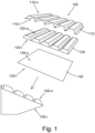
- example cooling elements 100 comprises a heat conduction layer 130, a plurality of elongate heat sink bars 120, and a heat retardant layer 110 (which may also be referred to as a thermal insulation layer).
- the heat conduction layer 130 consists essentially of a thin (for example, 1- 2 mm thick), substantially flat sheet of paper impregnated with a water-based solution (for example saline solution), a proximal (inner) side 130-i of which is intended to contact a body to be cooled (for example a bottle or can containing a beverage, not shown).
- the heat sink bars 120 may consist essentially of paper, or cardboard material, or other porous biodegradable (and / or compostable) material, impregnated with water, which water may be frozen or partially frozen when in use, or which water may be liquid water when in storage or transportation.
- each heat sink bar 120 has a substantially flat proximal (inner) side 120-i, which will contact a distal (outer) side 130-o of the heat conduction layer 130 when assembled, and an opposite distal (outer) side 120-o, which includes a flat surface area extending along the length of the heat sink bar 120.
- the distal (outer) sides 120-o of the heat sink bars 120 will contact a (proximal) inner side 110-i of the thermal barrier layer 110 when assembled for use.
- the thermal barrier layer 110 may be a substantially water-free (or dry) sheet of paper or carboard, having a corrugated form that is configured to accommodate the plurality of heat sink bars 120.
- the cooling element 100 When the cooling element 100 is assembled as in use, its distal (outermost) side will be at least partly defined by the distal (outer) side 110-o of the thermal barrier layer 110, and its proximal (innermost) side will be defined by the proximal (inner) side 130-i of the heat conduction layer 130.
- the innermost side of the cooling element 100 will contact a drinks container, such as a drink can or bottle (or other chilled product, in general) that is intended to be cooled (or to remain cooled), and the outermost side may be held by a user.
- the poor thermal conductivity of the heat retardant layer 110 will reduce the flux of heat from the ambient environment, including from the user's hand, to the heat sink bars 120, which may make it comfortable for the user to hold the chilled drink container, and reduce the rate at which the heat sink bars 120 heat towards the ambient temperature.
- the longer the heat sink bars 120 can be maintained below the ambient temperature the longer the cooling assembly 100 can function to chill the drink container (and consequently any beverage contained inside it).
- the heat conduction layer 130 comprises a porous matrix, such as fibrous material; for example, the porous matrix may comprise fibrous material such as paper or cardboard, which includes pores between the fibres.
- the pores are at least partly filled with an aqueous solution of sodium chloride (NaCl).
- NaCl sodium chloride
- the pores may include air bubbles, or unfilled voids, which may reduce the rate at which heat can be transported from the drink container to the heat sink bars 120, and which may be desired for reducing the rate of cooling of the drink container (or other body) and extending the period over which the drink container is maintained at temperatures below the ambient temperature.
- volume of unfilled pores that is, unfilled with aqueous solution
- volume of saline solution within the pores can be varied according the desired heat transport behaviour of the heat conduction layer 130 in use, depending on the kind of drink in a drink container, or the circumstances of use, for example.
- the temperature at which a saline solution will freeze will generally decrease as the dissolved salt content increases towards the saturation point.
- the freezing point of pure water is 0°C at one atmosphere of pressure, and the freezing point of saline solution having a NaCl content can be reduced by about 1 - 2°C.
- the impregnation of saline solution in the heat conduction layer 130 is understood to promote the transport of heat from the drink container, or other body to be cooled.
- the heat conduction layer 130 may be wrapped at least partly around, and against, a drink container (or other body) to be cooled.
- the saline solution should remain substantially unfrozen in use, heated by the heat being transported from the body, and may form a wetting contact with a surface of the drink container. Heat can diffuse from the body into the saline solution forming a good thermal contact with it, through the saline solution impregnated within the pores of the porous matrix of the heat conduction layer 130, and into the heat sink 120 (some saline solution may infiltrate into the heat sink elements to some extent).
- the heat sink bars 120 may comprise a porous matrix, such as fibrous material; for example, the porous matrix may comprise fibrous material such as paper or cardboard, which includes pores between the fibres.
- the pores may be impregnated with substantially pure water between the fibres.
- the water may be frozen or partly frozen, in use.
- the pores may contain saline solution, or some other aqueous solution, or emulsion; or the pores may contain a gel, or substantially non-aqueous medium.
- the porous matrix material of the heat sink bars 120, and / or the material with which the porous material is impregnated may be selected to enhance the ability of the heat sink bars 120 (or other configuration) to retain their shape as the ice melts, or the other impregnation medium liquifies, in use.
- the combined water content of the plurality of heat sink bars 120 may be of the order of 10 g, or 100 g; for example, the water content may be about 50 g to about 500 g.
- the shape of the heat sink volume may be configured according to the shape of the container, or other body, to be cooled; and / or the shape of the heat sink volume may be configured to be suitable for wrapping against surfaces having any of a range of shapes, such as curvatures.
- the heat sink volume is in the form of a plurality of bars, such that the relative disposition of neighbouring bars can be varied depending on the shape the drink container to be cooled.
- the heat sink volume 120 may comprise a single pre-shaped body, or a flexible sheet.
- the matrix material comprised in the heat sink bars 120 may be substantially the same, or different, kind of material that is comprised in the heat conduction layer 130.
- the thermal barrier sheet 110 may contain any of a wide range of materials that have a sufficiently low thermal conductivity, such that the risk of a user's hand becoming uncomfortably cold when they are holding the cooling element 100 in use; and / or such that the heat sink means 120 remains frozen for a sufficiently long period.
- the thermal barrier sheet 110 is formed of a thin sheet of paper or cardboard that is corrugated to conform the shapes of the outer sides 120-o of the heat sink bars 120.
- the type of material comprised in the thermal barrier layer 110 may be substantially the same, or different from, the porous matrix material comprised in the heat sink bars 120, and / or the matrix material comprised in the heat conduction layer 130.
- an example cooling element 100 may comprise a heat conduction layer 110, a plurality of heat sink bars 120 and a thermal barrier layer 130. These layers may be attached to each other by means of adhesive material, and may have the features and characteristics as described with reference to Fig. 1 .
- example cooling assemblies may comprise a carrier 200 for containing and carrying one or two (or more than two) drink cans 300, and a pair of cooling elements 100A, 100B.
- the carrier 200 may formed of cardboard and have a pair of ears that include through-holes as handles, to facilitate a user carrying the carrier 200, and drink cans 300 contained by it. While the carriers 200 in each of the examples have somewhat different configurations, both comprise a containment volume of sufficient size to accommodate two drink cans (for example, 330 ml capacity drink cans) and the pair of cooling elements 100A, 100A.
- Each of the cooling elements 100A, 100B may be as described with reference to Fig.
- each of the cooling elements 100A, 100B can be inserted between a respective drink can 300 and a respective end of the carrier 200, each having substantially the same semi-circular shape as the cylindrical side of the drink can 300.
- cooling elements 100A, 100B Prior to use, the cooling elements 100A, 100B will have been treated in a refrigerator or freezer to freeze the water or other medium impregnated into the porous matrix comprised in the heat sink bars 120. Each treated cooling element 100A, 100B can be inserted into the carrier 200, between a drink can 300 and a respective end of the containment volume of the carrier 200.
- each of the heat sink bars 120 includes a plurality of elongate cavities extending from one end of the heat sink bar 120 to the other.
- the presence of the cavities may have the aspect of reducing the amount of material within the cooling elements, and / or of achieving a desired cooling rate response.
- each of the heat sink bars 120 has four substantially flat longitudinal sides that extend between opposite ends, in which inner and outer sides are substantially parallel to each other, and connected to each other by tapered, non-parallel sides.
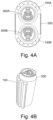
- an example cooling assembly may comprise a carrier 200 for containing and carrying a bottle 300, such as a wine bottle, and a pair of cooling elements 100A, 100B.
- the carrier 200 may formed of cardboard and have a pair of ears that include through-holes, to form handles and facilitate a user carrying the carrier, and potentially a wine bottle contained by it.
- the carrier 200 may comprise a containment volume of sufficient size to accommodate the bottle 300 (for example, a 750 ml capacity bottle) and the pair of inserts 100A, 100A.
- Each of the cooling elements 100A, 100B may be as described with reference to Figs.
- the heat sink bars 120 may have four substantially flat longitudinal sides that extend between opposite ends, each being substantially square, rectangular, or tapered when viewed in lateral cross-section (that is, in a plane perpendicular to the longitudinal axis of the heat-sink bar 120). As shown in Fig. 5D , each of the two cooling elements 100A, 100B can be inserted between opposite sides of the bottle 300 and a respective side of the carrier 200, each having substantially the same semi-circular shape as the cylindrical side of the bottle 300.
- the cardboard carrier 200 may be provided in compact form as shown in Fig. 5E , since it may be more efficient to pack and store the carrier 200 in a flat, folded form.
- a user may open the carrier 200 and place a bottle 300 (or in general some other body to be cooled) into the containment volume.
- the carrier 200 should be configured such that the containment volume is sufficiently wide to accommodate the bottle as well as at least a pair of cooling elements 100A, 100B between respective sides of the bottle 300 and the wall of the containment volume.
- Each cooling element 100A, 100B can be prepared by impregnating the porous matrix with water, and then placing them in a refrigerator at a temperature below the freezing point of water for a sufficiently long period for substantially all the water to freeze.
- the cooling element 100A, 100B can be bent into an arcuate form to match the curvature of the side of the bottle 300, and inserted between respective sides of the bottle 300 and the wall of the containment volume of the carrier 200, such that the proximal (inner) side 130-i of the heat conduction layer 130 is in contact with the respective side of the bottle 300.
- the heat sink volume 120 is in the form of a plurality of bars (six bars 120 in each cooling element 100, in this example) arranged substantially parallel to each other and connected by the heat conduction layer 130 on the proximal (inner) side 120-i and by the thermal barrier layer 110 on the distal (outer) side 120-o.
- This arrangement can allow the cooling element 100A, 100B to be bent sufficiently to match the curvature of the bottle 300, even when the heat sink bars 120 are frozen solid.
- wine contained within the bottle 300 may be cooled from about 24°C to about 15°C in approximately 15 minutes.
- the method of using the cooling assemblies for drink cans described with reference to Figs. 3A - 4C will be substantially the same as described with reference to Figs. 5A - 5E in connection with a wine bottle.
- the cardboard carriers 200 can be configured such that the same cooling elements 100A, 100B can be used in combination with a variety of drink containers, including cans and bottles; and the example cooling elements 100A, 100B may be bent into a range of curvatures, for use with various drink containers.
- the cooling elements 100A, 100B may be used with a range of drink cans and bottles.
- Certain example cooling elements may contain a relatively low content of water, and may have the aspect of promoting a sustainable environment and minimising the consumption of clean water, particularly in geographical regions in which water is relatively scarce. In various examples, it may be desirable for the amount of water, or other impregnated medium, contained within the heat sink, and / or within the heat conduction layer, to be relatively low, or to be minimised. In some examples, each cooling element may contain less than about 130 millilitres (ml) of water.
- Certain example cooling elements may have a relatively low content of salt within the heat conduction layer, and / or may comprise porous matrix material (comprised in the heat conduction member, and / or the heat sink means, and / or the thermal barrier layer) that is biodegradable (and / or compostable), and may have the aspect of being readily compostable, or recycled, and environmentally friendly.
- the cooling elements may be substantially entirely biodegradable (and / or compostable).
- Certain example cooling elements may be capable of being re-used one or more times; and in some examples, the carrier, and / or the heat sink means, and / or the thermal barrier layer, and / or the heat conduction layer may comprise or consist essentially of recycled cardboard (or other biodegradable and / or compostable material).
- Various example heat sink means may be impregnated, or impregnable, with water, and have the aspect of being readily frozen by means of a domestic refrigerator.
- Certain example cooling elements may comprise relatively few different kinds of material, and relatively few components having relatively simple shapes, and may have the aspect of being relatively straightforward to manufacture using simple equipment, potentially consuming relatively little energy in the process.
- 'wetting' refers to the ability of a liquid to maintain contact with the surface of a solid body, resulting from intermolecular interactions when the two are brought together. Wettability may be measured by a method involving placing a drop of the liquid onto the surface of the body, and determining the angle between the surface and a plane tangent to the surface of the drop, where the surface of the drop meets the surface of the body. The angle is included within the drop, and may be referred to as the 'contact angle'.
- a 'wetting contact' corresponds to a contact angle of less than 90° (in air).
- the phrase "consists essentially of” means “consists of, apart from a non-substantial content of practically unavoidable impurities”.
Landscapes
- Engineering & Computer Science (AREA)
- Physics & Mathematics (AREA)
- Thermal Sciences (AREA)
- Chemical & Material Sciences (AREA)
- Mechanical Engineering (AREA)
- Combustion & Propulsion (AREA)
- General Engineering & Computer Science (AREA)
- Food Science & Technology (AREA)
- Chemical Kinetics & Catalysis (AREA)
- Materials Engineering (AREA)
- Organic Chemistry (AREA)
- Table Equipment (AREA)
Claims (15)
- Kühlelement (100), umfassendeine Wärmeleitschicht (130), die an eine proximale Seite des Kühlelements angrenzt,eine wärmehemmende Schicht (110), die an eine distale Seite des Kühlelements angrenzt, undein Wärmesenke-Volumen (120), das zwischen der wärmeleitenden und der wärmehemmenden Schicht angeordnet ist und sich von einer proximalen Grenze (130-i) mit der wärmeleitenden Schicht zu einer distalen Grenze (110-0) mit der wärmehemmenden Schicht erstreckt;wobei das Wärmesenke-Volumen aus einem porösen Material besteht, dessen Poren im Wesentlichen mit einer ersten Substanz gefüllt sind; dadurch gekennzeichnet, dassdie Wärmeleitschicht (130) ein Flächenmaterial ist, das ein poröses Material umfasst, dessen Poren zumindest teilweise mit einer zweiten Substanz gefüllt sind, und das eine Außenfläche der proximalen Seite des Kühlelements bilden, die so konfiguriert ist, dass sie eine Oberfläche eines zu kühlenden Körpers berührt;wobei die erste und die zweite Substanz solche thermischen Eigenschaften haben, dass die erste Substanz sich bei einer ersten Temperatur von weniger als 20 °C verfestigt und die zweite Substanz bei der ersten Temperatur in flüssigem Zustand ist; unddie wärmehemmende Schicht (110) eine geringere mittlere Wärmeleitfähigkeit als die Wärmeleitschicht aufweist;und so konfiguriert, dass, wenn die äußere Oberfläche der proximalen Seite des Kühlelements die Oberfläche des Körpers berührt, die Wärmeleitschicht die Wärme schneller von dem Körper und in das Wärmesenke-Volumen (120) leitet, als die Wärme von der distalen Seite des Kühlelements durch die wärmehemmende Schicht und in das Volumen der Wärmesenke geleitet wird.
- Kühlelement nach Anspruch 1, wobei das Wärmesenke-Volumen (120) eine Vielzahl von Wärmesenke-Elementen umfasst.
- Kühlelement nach einem der vorhergehenden Ansprüche, bei dem das poröse Material des Wärmesenke-Volumens (120) ein biologisch abbaubares und/oder kompostierbares Material umfasst.
- Kühlelement nach einem der vorhergehenden Ansprüche, wobei das poröse Material der Wärmeleitschicht (130) ein biologisch abbaubares und/oder kompostierbares Material ist.
- Kühlelement nach einem der vorhergehenden Ansprüche, wobei die wärmehemmende Schicht (110) ein biologisch abbaubares und/oder kompostierbares Material ist.
- Kühlelement nach einem der Ansprüche 4 oder 5, wobei das poröse Material der Wärmeleitschicht und das poröse Material des Wärmesenke-Volumens sowie die wärmehemmende Schicht biologisch abbaubar und/oder kompostierbar sind.
- Kühlelement nach einem der Ansprüche 4 bis 6, wobei das biologisch abbaubare und/oder kompostierbare Material mindestens eines der folgenden Materialien umfasst: Papier, Pappe, Hanffasern, Bambusfasern oder Holzfaserstoff.
- Kühlelement nach einem der vorhergehenden Ansprüche, bei dem das Volumen der Wärmeleitschicht (130) kleiner ist als das Volumen des Wärmesenke-Volumens (120).
- Kühlelement nach einem der vorhergehenden Ansprüche, bei dem die erste Substanz Wasser umfasst.
- Kühlelement nach einem der vorhergehenden Ansprüche, bei dem die zweite Substanz eine Lösung von Natriumchlorid in Wasser umfasst.
- Kühlelement nach einem der vorhergehenden Ansprüche, bei dem die mittlere Dicke der Wärmeleitschicht (130) 0,5-3 mm beträgt.
- Kühlelement nach einem der vorhergehenden Ansprüche, bei dem die mittlere Dicke der wärmehemmenden Schicht (110) 1-15 mm beträgt.
- Kühlanordnung zum Kühlen eines Körpers, umfassend ein oder mehrere Kühlelemente (100) nach einem der vorhergehenden Ansprüche und einen Behälter zur Aufnahme des Körpers und des Kühlelements.
- Kühlanordnung nach Anspruch 13, die eine Vielzahl von Kühlelementen umfasst.
- Verfahren zum Kühlen eines Körpers, wobei das Verfahren beinhaltet: Bereitstellen einer Kühlanordnung nach Anspruch 13 oder 14; Verringern der Temperatur des Wärmesenke-Volumens auf weniger als die erste Temperatur; Anordnen des Kühlelements zwischen dem Körper und einer Oberfläche des Behälters, wobei der Körper in dem Behälter untergebracht ist; wobei die proximale Seite des Kühlelements in Kontakt mit dem Körper ist.
Applications Claiming Priority (2)
| Application Number | Priority Date | Filing Date | Title |
|---|---|---|---|
| GB1717363.4A GB2567690B (en) | 2017-10-23 | 2017-10-23 | Cooling elements and cooling assemblies comprising same |
| PCT/EP2018/078549 WO2019081337A1 (en) | 2017-10-23 | 2018-10-18 | Cooling elements and cooling assemblies comprising same |
Publications (3)
| Publication Number | Publication Date |
|---|---|
| EP3701203A1 EP3701203A1 (de) | 2020-09-02 |
| EP3701203C0 EP3701203C0 (de) | 2024-07-24 |
| EP3701203B1 true EP3701203B1 (de) | 2024-07-24 |
Family
ID=60481711
Family Applications (1)
| Application Number | Title | Priority Date | Filing Date |
|---|---|---|---|
| EP18793384.1A Active EP3701203B1 (de) | 2017-10-23 | 2018-10-18 | Kühlelemente und diese enthaltende kühlanordnungen |
Country Status (5)
| Country | Link |
|---|---|
| US (1) | US11745931B2 (de) |
| EP (1) | EP3701203B1 (de) |
| CN (1) | CN111527358B (de) |
| GB (1) | GB2567690B (de) |
| WO (1) | WO2019081337A1 (de) |
Families Citing this family (3)
| Publication number | Priority date | Publication date | Assignee | Title |
|---|---|---|---|---|
| US10046901B1 (en) * | 2017-02-16 | 2018-08-14 | Vericool, Inc. | Thermally insulating packaging |
| CN110858141B (zh) * | 2018-08-23 | 2023-07-28 | 西门子股份公司 | 分层架构软件中代码评估方法、装置及存储介质 |
| US11685570B2 (en) * | 2020-05-15 | 2023-06-27 | Acorn West LLC | Thermal regulating lay flat beverage container packaging |
Citations (1)
| Publication number | Priority date | Publication date | Assignee | Title |
|---|---|---|---|---|
| WO2008072098A1 (en) * | 2006-12-15 | 2008-06-19 | Kimberly-Clark Worldwide, Inc. | A self-activated cooling device |
Family Cites Families (18)
| Publication number | Priority date | Publication date | Assignee | Title |
|---|---|---|---|---|
| GB1185811A (en) * | 1966-02-22 | 1970-03-25 | Eric Ronald Paxman | Improvements in or relating to the Refrigeration of Containers |
| JPS6467579A (en) | 1987-09-08 | 1989-03-14 | Sakura Sogyo Kk | Heat accumulator and cooling method thereof |
| JPH0733100Y2 (ja) * | 1988-05-19 | 1995-07-31 | 三順 中嶋 | ジョッキ用保冷具 |
| US5269368A (en) * | 1991-08-05 | 1993-12-14 | Vacu Products B.V. | Rechargeable temperature regulating device for controlling the temperature of a beverage or other object |
| GB9320747D0 (en) * | 1993-10-08 | 1993-12-01 | Scholl Plc | A compress for use in the cold and/or hot treatment of an injury |
| US6266972B1 (en) * | 1998-12-07 | 2001-07-31 | Vesture Corporation | Modular freezer pallet and method for storing perishable items |
| US7055575B2 (en) * | 2002-10-18 | 2006-06-06 | Noel Thomas P | Thermally active convection apparatus |
| ATE280370T1 (de) | 2001-09-18 | 2004-11-15 | Schaefer Werke Gmbh | Kühlvorrichtung zur kontaktkühlung |
| FR2843190B1 (fr) | 2002-07-31 | 2005-01-28 | Daniel Cholet | Bloc accumulateur thermique recyclable a detection de fuite pour emballages isothermes |
| US7240514B2 (en) * | 2005-03-28 | 2007-07-10 | Gary Lonnie F | Reduced volume carrier for canned or bottled beverages |
| NL1029083C2 (nl) * | 2005-05-20 | 2006-11-21 | Breedveldt Beheer B V M | Inrichting voor het koelen van voorwerpen, in het bijzonder een koelmantel voor drankcontainers. |
| US8448809B2 (en) * | 2007-10-15 | 2013-05-28 | Millercoors, Llc | Thermal barrier liner for containers |
| WO2013123561A1 (en) * | 2012-02-22 | 2013-08-29 | Alfio Bucceri | Method of, and apparatus for, making frozen beverages, ice cream and other frozen confections |
| US10337784B2 (en) * | 2013-02-20 | 2019-07-02 | Doubleday Acquisitions Llc | Phase change material (PCM) belts |
| US10544977B2 (en) * | 2013-05-08 | 2020-01-28 | Susan Leslie | Portable cooling system |
| US20150096995A1 (en) * | 2013-10-03 | 2015-04-09 | Brent Eugene Cunningham | System for Maintaining Beverage Temperature |
| US9920983B1 (en) | 2015-02-09 | 2018-03-20 | Hyperbius, Inc. | Quick-chill beverage chiller having multiple reservoirs |
| GB2560825A (en) * | 2017-03-20 | 2018-09-26 | Havi Global Solutions Europe Ltd | Food packaging |
-
2017
- 2017-10-23 GB GB1717363.4A patent/GB2567690B/en active Active
-
2018
- 2018-10-18 US US15/733,027 patent/US11745931B2/en active Active
- 2018-10-18 CN CN201880069143.4A patent/CN111527358B/zh active Active
- 2018-10-18 WO PCT/EP2018/078549 patent/WO2019081337A1/en not_active Ceased
- 2018-10-18 EP EP18793384.1A patent/EP3701203B1/de active Active
Patent Citations (1)
| Publication number | Priority date | Publication date | Assignee | Title |
|---|---|---|---|---|
| WO2008072098A1 (en) * | 2006-12-15 | 2008-06-19 | Kimberly-Clark Worldwide, Inc. | A self-activated cooling device |
Also Published As
| Publication number | Publication date |
|---|---|
| GB2567690A (en) | 2019-04-24 |
| GB201717363D0 (en) | 2017-12-06 |
| US11745931B2 (en) | 2023-09-05 |
| WO2019081337A1 (en) | 2019-05-02 |
| EP3701203C0 (de) | 2024-07-24 |
| GB2567690B (en) | 2019-10-23 |
| CN111527358A (zh) | 2020-08-11 |
| EP3701203A1 (de) | 2020-09-02 |
| US20210221594A1 (en) | 2021-07-22 |
| CN111527358B (zh) | 2022-08-30 |
Similar Documents
| Publication | Publication Date | Title |
|---|---|---|
| EP3701203B1 (de) | Kühlelemente und diese enthaltende kühlanordnungen | |
| US4931333A (en) | Thermal packaging assembly | |
| US5609039A (en) | Cooling cartridge for plastic drinking bottles | |
| DK171177B1 (da) | Fremgangsmåde og beholder for lagring og distribution af fødevarer | |
| US6128915A (en) | Portable food and beverage cooling device | |
| US20090320517A1 (en) | Cooler and cooler accessory with integrated liquid dispenser | |
| GB2383122A (en) | A temperature regulator | |
| US20150182053A1 (en) | Beverage coaster | |
| US5875646A (en) | Device for cooling food and beverages especially for an infant | |
| US20080308563A1 (en) | Subcontainer temperature regulating mechanism | |
| US20210025660A1 (en) | System and method for active cooling of a substance | |
| US7228712B1 (en) | Synthetic ice and associated methods | |
| NL1029083C2 (nl) | Inrichting voor het koelen van voorwerpen, in het bijzonder een koelmantel voor drankcontainers. | |
| US20080276642A1 (en) | Cooler and cooler accessory with integrated liquid dispenser | |
| JP4735875B2 (ja) | 飲料容器 | |
| RU2186715C2 (ru) | Устройство для хранения продуктов при низких температурах | |
| BE1028814B1 (nl) | Gebruik van een eutectisch medium of een medium met laag smeltpunt voor het afkoelen en koud houden van biologische actieve materialen zoals vaccins op een zeer lage temperatuur, koelinrichting hiervoor, en werkwijze voor het produceren van houders omvattende dergelijk eutectisch medium of medium met laag smeltpunt | |
| RU2186304C1 (ru) | Устройство для хранения продуктов | |
| JP7083586B1 (ja) | 保冷剤ケース | |
| WO2010143958A2 (en) | Cooler for a glass, can, bottle or mug | |
| RU2198357C2 (ru) | Устройство для хранения продуктов | |
| JP2017214157A (ja) | 飲料容器 | |
| JP2016145085A (ja) | 飲料容器 | |
| JP2011121648A (ja) | 飲料容器 | |
| JP2015037975A (ja) | 飲料容器 |
Legal Events
| Date | Code | Title | Description |
|---|---|---|---|
| STAA | Information on the status of an ep patent application or granted ep patent |
Free format text: STATUS: UNKNOWN |
|
| STAA | Information on the status of an ep patent application or granted ep patent |
Free format text: STATUS: THE INTERNATIONAL PUBLICATION HAS BEEN MADE |
|
| PUAI | Public reference made under article 153(3) epc to a published international application that has entered the european phase |
Free format text: ORIGINAL CODE: 0009012 |
|
| STAA | Information on the status of an ep patent application or granted ep patent |
Free format text: STATUS: REQUEST FOR EXAMINATION WAS MADE |
|
| 17P | Request for examination filed |
Effective date: 20200427 |
|
| AK | Designated contracting states |
Kind code of ref document: A1 Designated state(s): AL AT BE BG CH CY CZ DE DK EE ES FI FR GB GR HR HU IE IS IT LI LT LU LV MC MK MT NL NO PL PT RO RS SE SI SK SM TR |
|
| AX | Request for extension of the european patent |
Extension state: BA ME |
|
| DAV | Request for validation of the european patent (deleted) | ||
| DAX | Request for extension of the european patent (deleted) | ||
| RAP1 | Party data changed (applicant data changed or rights of an application transferred) |
Owner name: GREEN CHILLY LIMITED |
|
| RIN1 | Information on inventor provided before grant (corrected) |
Inventor name: INGAM, PHILIP ROBERT Inventor name: MARSHALL-REES, STEPHEN |
|
| STAA | Information on the status of an ep patent application or granted ep patent |
Free format text: STATUS: EXAMINATION IS IN PROGRESS |
|
| 17Q | First examination report despatched |
Effective date: 20220927 |
|
| GRAP | Despatch of communication of intention to grant a patent |
Free format text: ORIGINAL CODE: EPIDOSNIGR1 |
|
| STAA | Information on the status of an ep patent application or granted ep patent |
Free format text: STATUS: GRANT OF PATENT IS INTENDED |
|
| INTG | Intention to grant announced |
Effective date: 20240307 |
|
| GRAS | Grant fee paid |
Free format text: ORIGINAL CODE: EPIDOSNIGR3 |
|
| GRAA | (expected) grant |
Free format text: ORIGINAL CODE: 0009210 |
|
| STAA | Information on the status of an ep patent application or granted ep patent |
Free format text: STATUS: THE PATENT HAS BEEN GRANTED |
|
| AK | Designated contracting states |
Kind code of ref document: B1 Designated state(s): AL AT BE BG CH CY CZ DE DK EE ES FI FR GB GR HR HU IE IS IT LI LT LU LV MC MK MT NL NO PL PT RO RS SE SI SK SM TR |
|
| REG | Reference to a national code |
Ref country code: GB Ref legal event code: FG4D |
|
| REG | Reference to a national code |
Ref country code: CH Ref legal event code: EP |
|
| REG | Reference to a national code |
Ref country code: IE Ref legal event code: FG4D Ref country code: DE Ref legal event code: R096 Ref document number: 602018072227 Country of ref document: DE |
|
| U01 | Request for unitary effect filed |
Effective date: 20240823 |
|
| U07 | Unitary effect registered |
Designated state(s): AT BE BG DE DK EE FI FR IT LT LU LV MT NL PT RO SE SI Effective date: 20240903 |
|
| U20 | Renewal fee for the european patent with unitary effect paid |
Year of fee payment: 7 Effective date: 20241009 |
|
| PG25 | Lapsed in a contracting state [announced via postgrant information from national office to epo] |
Ref country code: NO Free format text: LAPSE BECAUSE OF FAILURE TO SUBMIT A TRANSLATION OF THE DESCRIPTION OR TO PAY THE FEE WITHIN THE PRESCRIBED TIME-LIMIT Effective date: 20241024 |
|
| PG25 | Lapsed in a contracting state [announced via postgrant information from national office to epo] |
Ref country code: PL Free format text: LAPSE BECAUSE OF FAILURE TO SUBMIT A TRANSLATION OF THE DESCRIPTION OR TO PAY THE FEE WITHIN THE PRESCRIBED TIME-LIMIT Effective date: 20240724 Ref country code: GR Free format text: LAPSE BECAUSE OF FAILURE TO SUBMIT A TRANSLATION OF THE DESCRIPTION OR TO PAY THE FEE WITHIN THE PRESCRIBED TIME-LIMIT Effective date: 20241025 |
|
| U1N | Appointed representative for the unitary patent procedure changed after the registration of the unitary effect |
Representative=s name: STANNERS, DAVID RALPH; GB |
|
| PG25 | Lapsed in a contracting state [announced via postgrant information from national office to epo] |
Ref country code: IS Free format text: LAPSE BECAUSE OF FAILURE TO SUBMIT A TRANSLATION OF THE DESCRIPTION OR TO PAY THE FEE WITHIN THE PRESCRIBED TIME-LIMIT Effective date: 20241124 |
|
| PG25 | Lapsed in a contracting state [announced via postgrant information from national office to epo] |
Ref country code: HR Free format text: LAPSE BECAUSE OF FAILURE TO SUBMIT A TRANSLATION OF THE DESCRIPTION OR TO PAY THE FEE WITHIN THE PRESCRIBED TIME-LIMIT Effective date: 20240724 |
|
| PG25 | Lapsed in a contracting state [announced via postgrant information from national office to epo] |
Ref country code: RS Free format text: LAPSE BECAUSE OF FAILURE TO SUBMIT A TRANSLATION OF THE DESCRIPTION OR TO PAY THE FEE WITHIN THE PRESCRIBED TIME-LIMIT Effective date: 20241024 Ref country code: ES Free format text: LAPSE BECAUSE OF FAILURE TO SUBMIT A TRANSLATION OF THE DESCRIPTION OR TO PAY THE FEE WITHIN THE PRESCRIBED TIME-LIMIT Effective date: 20240724 |
|
| PG25 | Lapsed in a contracting state [announced via postgrant information from national office to epo] |
Ref country code: RS Free format text: LAPSE BECAUSE OF FAILURE TO SUBMIT A TRANSLATION OF THE DESCRIPTION OR TO PAY THE FEE WITHIN THE PRESCRIBED TIME-LIMIT Effective date: 20241024 Ref country code: PL Free format text: LAPSE BECAUSE OF FAILURE TO SUBMIT A TRANSLATION OF THE DESCRIPTION OR TO PAY THE FEE WITHIN THE PRESCRIBED TIME-LIMIT Effective date: 20240724 Ref country code: NO Free format text: LAPSE BECAUSE OF FAILURE TO SUBMIT A TRANSLATION OF THE DESCRIPTION OR TO PAY THE FEE WITHIN THE PRESCRIBED TIME-LIMIT Effective date: 20241024 Ref country code: IS Free format text: LAPSE BECAUSE OF FAILURE TO SUBMIT A TRANSLATION OF THE DESCRIPTION OR TO PAY THE FEE WITHIN THE PRESCRIBED TIME-LIMIT Effective date: 20241124 Ref country code: HR Free format text: LAPSE BECAUSE OF FAILURE TO SUBMIT A TRANSLATION OF THE DESCRIPTION OR TO PAY THE FEE WITHIN THE PRESCRIBED TIME-LIMIT Effective date: 20240724 Ref country code: GR Free format text: LAPSE BECAUSE OF FAILURE TO SUBMIT A TRANSLATION OF THE DESCRIPTION OR TO PAY THE FEE WITHIN THE PRESCRIBED TIME-LIMIT Effective date: 20241025 Ref country code: ES Free format text: LAPSE BECAUSE OF FAILURE TO SUBMIT A TRANSLATION OF THE DESCRIPTION OR TO PAY THE FEE WITHIN THE PRESCRIBED TIME-LIMIT Effective date: 20240724 |
|
| PG25 | Lapsed in a contracting state [announced via postgrant information from national office to epo] |
Ref country code: SM Free format text: LAPSE BECAUSE OF FAILURE TO SUBMIT A TRANSLATION OF THE DESCRIPTION OR TO PAY THE FEE WITHIN THE PRESCRIBED TIME-LIMIT Effective date: 20240724 |
|
| PG25 | Lapsed in a contracting state [announced via postgrant information from national office to epo] |
Ref country code: CZ Free format text: LAPSE BECAUSE OF FAILURE TO SUBMIT A TRANSLATION OF THE DESCRIPTION OR TO PAY THE FEE WITHIN THE PRESCRIBED TIME-LIMIT Effective date: 20240724 |
|
| PG25 | Lapsed in a contracting state [announced via postgrant information from national office to epo] |
Ref country code: SK Free format text: LAPSE BECAUSE OF FAILURE TO SUBMIT A TRANSLATION OF THE DESCRIPTION OR TO PAY THE FEE WITHIN THE PRESCRIBED TIME-LIMIT Effective date: 20240724 |
|
| PLBE | No opposition filed within time limit |
Free format text: ORIGINAL CODE: 0009261 |
|
| STAA | Information on the status of an ep patent application or granted ep patent |
Free format text: STATUS: NO OPPOSITION FILED WITHIN TIME LIMIT |
|
| REG | Reference to a national code |
Ref country code: CH Ref legal event code: PL |
|
| GBPC | Gb: european patent ceased through non-payment of renewal fee |
Effective date: 20241024 |
|
| 26N | No opposition filed |
Effective date: 20250425 |
|
| PG25 | Lapsed in a contracting state [announced via postgrant information from national office to epo] |
Ref country code: MC Free format text: LAPSE BECAUSE OF FAILURE TO SUBMIT A TRANSLATION OF THE DESCRIPTION OR TO PAY THE FEE WITHIN THE PRESCRIBED TIME-LIMIT Effective date: 20240724 |
|
| PG25 | Lapsed in a contracting state [announced via postgrant information from national office to epo] |
Ref country code: GB Free format text: LAPSE BECAUSE OF NON-PAYMENT OF DUE FEES Effective date: 20241024 |
|
| PG25 | Lapsed in a contracting state [announced via postgrant information from national office to epo] |
Ref country code: CH Free format text: LAPSE BECAUSE OF NON-PAYMENT OF DUE FEES Effective date: 20241031 |
|
| U20 | Renewal fee for the european patent with unitary effect paid |
Year of fee payment: 8 Effective date: 20250829 |
|
| PG25 | Lapsed in a contracting state [announced via postgrant information from national office to epo] |
Ref country code: IE Free format text: LAPSE BECAUSE OF NON-PAYMENT OF DUE FEES Effective date: 20241018 |
|
| PG25 | Lapsed in a contracting state [announced via postgrant information from national office to epo] |
Ref country code: CY Free format text: LAPSE BECAUSE OF FAILURE TO SUBMIT A TRANSLATION OF THE DESCRIPTION OR TO PAY THE FEE WITHIN THE PRESCRIBED TIME-LIMIT; INVALID AB INITIO Effective date: 20181018 |
|
| PG25 | Lapsed in a contracting state [announced via postgrant information from national office to epo] |
Ref country code: HU Free format text: LAPSE BECAUSE OF FAILURE TO SUBMIT A TRANSLATION OF THE DESCRIPTION OR TO PAY THE FEE WITHIN THE PRESCRIBED TIME-LIMIT; INVALID AB INITIO Effective date: 20181018 |