EP3700787B1 - Fluidbehälter mit einem sperrventil - Google Patents
Fluidbehälter mit einem sperrventil Download PDFInfo
- Publication number
- EP3700787B1 EP3700787B1 EP18796369.9A EP18796369A EP3700787B1 EP 3700787 B1 EP3700787 B1 EP 3700787B1 EP 18796369 A EP18796369 A EP 18796369A EP 3700787 B1 EP3700787 B1 EP 3700787B1
- Authority
- EP
- European Patent Office
- Prior art keywords
- valve
- receiving seat
- assembly
- shut
- connecting channel
- Prior art date
- Legal status (The legal status is an assumption and is not a legal conclusion. Google has not performed a legal analysis and makes no representation as to the accuracy of the status listed.)
- Active
Links
Images

Classifications
-
- B—PERFORMING OPERATIONS; TRANSPORTING
- B60—VEHICLES IN GENERAL
- B60T—VEHICLE BRAKE CONTROL SYSTEMS OR PARTS THEREOF; BRAKE CONTROL SYSTEMS OR PARTS THEREOF, IN GENERAL; ARRANGEMENT OF BRAKING ELEMENTS ON VEHICLES IN GENERAL; PORTABLE DEVICES FOR PREVENTING UNWANTED MOVEMENT OF VEHICLES; VEHICLE MODIFICATIONS TO FACILITATE COOLING OF BRAKES
- B60T17/00—Component parts, details, or accessories of power brake systems not covered by groups B60T8/00, B60T13/00 or B60T15/00, or presenting other characteristic features
- B60T17/04—Arrangements of piping, valves in the piping, e.g. cut-off valves, couplings or air hoses
- B60T17/043—Brake line couplings, air hoses and stopcocks
-
- B—PERFORMING OPERATIONS; TRANSPORTING
- B60—VEHICLES IN GENERAL
- B60T—VEHICLE BRAKE CONTROL SYSTEMS OR PARTS THEREOF; BRAKE CONTROL SYSTEMS OR PARTS THEREOF, IN GENERAL; ARRANGEMENT OF BRAKING ELEMENTS ON VEHICLES IN GENERAL; PORTABLE DEVICES FOR PREVENTING UNWANTED MOVEMENT OF VEHICLES; VEHICLE MODIFICATIONS TO FACILITATE COOLING OF BRAKES
- B60T11/00—Transmitting braking action from initiating means to ultimate brake actuator without power assistance or drive or where such assistance or drive is irrelevant
- B60T11/10—Transmitting braking action from initiating means to ultimate brake actuator without power assistance or drive or where such assistance or drive is irrelevant transmitting by fluid means, e.g. hydraulic
- B60T11/26—Reservoirs
-
- B—PERFORMING OPERATIONS; TRANSPORTING
- B60—VEHICLES IN GENERAL
- B60T—VEHICLE BRAKE CONTROL SYSTEMS OR PARTS THEREOF; BRAKE CONTROL SYSTEMS OR PARTS THEREOF, IN GENERAL; ARRANGEMENT OF BRAKING ELEMENTS ON VEHICLES IN GENERAL; PORTABLE DEVICES FOR PREVENTING UNWANTED MOVEMENT OF VEHICLES; VEHICLE MODIFICATIONS TO FACILITATE COOLING OF BRAKES
- B60T11/00—Transmitting braking action from initiating means to ultimate brake actuator without power assistance or drive or where such assistance or drive is irrelevant
- B60T11/10—Transmitting braking action from initiating means to ultimate brake actuator without power assistance or drive or where such assistance or drive is irrelevant transmitting by fluid means, e.g. hydraulic
- B60T11/28—Valves specially adapted therefor
- B60T11/32—Automatic cut-off valves for defective pipes
- B60T11/323—Automatic cut-off valves for defective pipes in hydraulic systems
-
- B—PERFORMING OPERATIONS; TRANSPORTING
- B60—VEHICLES IN GENERAL
- B60T—VEHICLE BRAKE CONTROL SYSTEMS OR PARTS THEREOF; BRAKE CONTROL SYSTEMS OR PARTS THEREOF, IN GENERAL; ARRANGEMENT OF BRAKING ELEMENTS ON VEHICLES IN GENERAL; PORTABLE DEVICES FOR PREVENTING UNWANTED MOVEMENT OF VEHICLES; VEHICLE MODIFICATIONS TO FACILITATE COOLING OF BRAKES
- B60T17/00—Component parts, details, or accessories of power brake systems not covered by groups B60T8/00, B60T13/00 or B60T15/00, or presenting other characteristic features
- B60T17/06—Applications or arrangements of reservoirs
-
- B—PERFORMING OPERATIONS; TRANSPORTING
- B60—VEHICLES IN GENERAL
- B60T—VEHICLE BRAKE CONTROL SYSTEMS OR PARTS THEREOF; BRAKE CONTROL SYSTEMS OR PARTS THEREOF, IN GENERAL; ARRANGEMENT OF BRAKING ELEMENTS ON VEHICLES IN GENERAL; PORTABLE DEVICES FOR PREVENTING UNWANTED MOVEMENT OF VEHICLES; VEHICLE MODIFICATIONS TO FACILITATE COOLING OF BRAKES
- B60T17/00—Component parts, details, or accessories of power brake systems not covered by groups B60T8/00, B60T13/00 or B60T15/00, or presenting other characteristic features
- B60T17/18—Safety devices; Monitoring
- B60T17/22—Devices for monitoring or checking brake systems; Signal devices
- B60T17/221—Procedure or apparatus for checking or keeping in a correct functioning condition of brake systems
- B60T17/222—Procedure or apparatus for checking or keeping in a correct functioning condition of brake systems by filling or bleeding of hydraulic systems
-
- B—PERFORMING OPERATIONS; TRANSPORTING
- B60—VEHICLES IN GENERAL
- B60T—VEHICLE BRAKE CONTROL SYSTEMS OR PARTS THEREOF; BRAKE CONTROL SYSTEMS OR PARTS THEREOF, IN GENERAL; ARRANGEMENT OF BRAKING ELEMENTS ON VEHICLES IN GENERAL; PORTABLE DEVICES FOR PREVENTING UNWANTED MOVEMENT OF VEHICLES; VEHICLE MODIFICATIONS TO FACILITATE COOLING OF BRAKES
- B60T11/00—Transmitting braking action from initiating means to ultimate brake actuator without power assistance or drive or where such assistance or drive is irrelevant
- B60T11/10—Transmitting braking action from initiating means to ultimate brake actuator without power assistance or drive or where such assistance or drive is irrelevant transmitting by fluid means, e.g. hydraulic
- B60T11/28—Valves specially adapted therefor
-
- B—PERFORMING OPERATIONS; TRANSPORTING
- B60—VEHICLES IN GENERAL
- B60Y—INDEXING SCHEME RELATING TO ASPECTS CROSS-CUTTING VEHICLE TECHNOLOGY
- B60Y2400/00—Special features of vehicle units
- B60Y2400/81—Braking systems
Definitions
- the invention relates to an assembly for generating brake pressure in a hydraulic motor vehicle brake system with a fluid reservoir, according to the preamble of the independent claims.
- Such generic fluid reservoirs have one or more, usually two, connecting pieces assigned to the individual brake circuits, each equipped with an internal hydraulic connection channel, which are inserted into corresponding receiving seats directly on the associated brake unit or a separate interface adapter.
- connecting pieces assigned to the individual brake circuits, each equipped with an internal hydraulic connection channel, which are inserted into corresponding receiving seats directly on the associated brake unit or a separate interface adapter.
- DE 10 2014 207 839 A1 For example, a check valve is known which is installed directly in the connecting channel.
- DE 10 2014 213 709 A1 Another generic shut-off valve is known, which is designed as a separate valve module for insertion into the connecting channel.
- shut-off valves Just like a DE 3912110 A1
- actuating element for actuating a valve closing body such shut-off valves have a shaft-like, extended valve closing body that protrudes outward from the connection piece, thus protruding from the fluid container, when the valve is closed.
- the valve closing body When inserted into the receiving seat, the valve closing body rests against the base of the receiving seat, is thereby forcibly pushed into the fluid container, and thus opens the valve.
- a disadvantage is that in extreme cases such a valve could also be actuated unintentionally, for example by bending, breaking off or otherwise damaging the valve closing body or by its unintentional support on some other object.
- the invention is therefore based on the object of offering an improved solution against unintentional emptying of the fluid container, which could be realized cost-effectively and, if possible, as a subsequent modification.
- the unit may be, for example and not by way of limitation, a brake master cylinder or a hydraulic brake booster, a hydraulic brake pressure modulation device, or any combination of the foregoing.
- the invention proposes providing the check valve as a separate component, which is positioned separately in the receiving seat prior to assembly of the fluid container.
- a particularly conical recess is provided in the bottom of the receiving seat, into which the support means designed as a ball is inserted.
- a separate fastening bore is formed in the base of the receiving seat and a fastening pin is formed on the support means, which engages in a fastening bore in a force-locking manner for fixing.
- the support means is rounded on the valve closing body side and preferably has a substantially point-shaped contact point with the valve closing body. This can reduce friction with the valve closing body and consequently its incorrect operation, for example due to tilting. At the same time, the flow resistance for the brake fluid flowing through during operation is also reduced and optimized.
- the fluid reservoir 1 has a connection piece 3 formed on its reservoir bottom, which is inserted into a receiving seat 4 of the unit 2, in this case a master brake cylinder, and is sealed against the inner surface of the receiving seat 4 by means of a shaped seal 15.
- the connecting piece 3 is essentially tubular with an internal connecting channel 5.
- a shut-off valve 7 is arranged in the connecting channel 5.
- the brake fluid flows from the reservoir interior into the unit 2 via the connecting channel 5 and a passage 19 provided in the receiving seat 4.
- the check valve 7 has a shaft-like, extended valve closing body 8 that is axially displaceable in the connecting channel 5. At its upper end, directed toward the container interior 6, a sealing element 17 is arranged on the valve closing body 8, which, in a closed state of the check valve 7 (not shown here), is pressed against a valve seat 18 by the valve spring 16, thus blocking the connecting channel 5.
- the lower end 20 of the valve closing body 8 directed towards the receiving seat 4 projects outwards beyond the outer axial edge 9 of the connecting piece 3 and rests against the bottom 11 of the receiving seat 4. As a result, the valve closing body 8 is pushed into the connecting piece 3 in the direction of the container interior 6 and the sealing element 17 is lifted from the valve seat 18.
- Fig.2 shows a further embodiment of the fluid container 1.
- the valve closing body 8 is designed to be so short that its lower end 20 directed towards the receiving seat 4 is located completely within the connecting channel 5 even when the shut-off valve 7 is closed and does not protrude outwards beyond the contour which is formed by the outer edge 9 of the connecting piece 3.
- a separate support means 10 is provided in the receiving seat 4.
- the support means 10 is designed as a projection integrally formed on the base 11 of the receiving seat 4 and extending axially toward the connecting piece 3.
- the projection is essentially conical with a rounded end, so that a substantially point-shaped contact point exists with the valve closing body 8.
- the support means 10 engages directly into the connecting channel 5 of the connecting piece 3 and thus displaces the valve closing body 8 shortened according to the invention in the direction of the container interior 6 and the sealing element 17 from the valve seat 18.
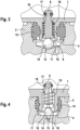
- Fig.3 shows a first embodiment of the fluid container 1 according to the invention.
- the support means 10 is provided as a ball that is inserted into the receiving seat 4.
- a recess 12 is provided in the base 10 of the receiving seat.
- the entire base 11 is designed in a conical, trough-shaped manner, whereby a ball inserted therein is forcibly self-centered solely by the effect of gravity.
- Fig.4 shows a second embodiment of the fluid container 1 according to the invention.
- the support means 10 is provided as a separate insert part, which, however, in contrast to the embodiment according to Fig.3 is fixed in the receiving seat 4.
- a fastening bore 13 is formed in the base 11 of the receiving seat 4, and a corresponding fastening pin 14 is provided on the support means 10, which is inserted into the fastening bore 13 in a force-fitting manner.
- a reverse principle as well as a positive connection, for example by means of a thread, or a material connection by means of adhesive bonding are possible and permissible at any time within the invention.
- the insert part is spherically rounded on the valve closing body side.
Landscapes
- Engineering & Computer Science (AREA)
- Transportation (AREA)
- Mechanical Engineering (AREA)
- Lift Valve (AREA)
- Check Valves (AREA)
- Transmission Of Braking Force In Braking Systems (AREA)
- Valves And Accessory Devices For Braking Systems (AREA)
Description
- Die Erfindung bezieht sich auf ein Aggregat zur Erzeugung von Bremsdruck in einer hydraulischen Kraftfahrzeugbremsanlage mit einem Fluidbehälter, nach dem Oberbegriff der unabhängigen Ansprüche.
- Derartige gattungsgemäße Fluidbehälter weisen einen oder mehrere, meistens zwei, den einzelnen Bremskreisen zugeordnete mit je einem internen hydraulischen Verbindungskanal ausgestattete Anschlussstutzen, welche in korrespondierende Aufnahmesitze unmittelbar am zugeordneten Bremsaggregat oder einem gesonderten Schnittstellenadapter eingesetzt werden. Insbesondere aus Sicherheitsgründen ergibt sich eine naheliegende Forderung, ein ungewolltes Entweichen der brennbaren Bremsflüssigkeit aus dem Fluidbehälter gerade dann zu verhindern, wenn die Anschlussstutzen sich nicht in den dafür vorgesehenen Aufnahmesitzen befinden. Dies kann beispielsweise bei Demontage des gefüllten Fluidbehälters im Servicefall oder einem Lösen des Fluidbehälters infolge eines ungewollten Ereignisses wie ein Crash der Fall sein.
- Hierzu ist es grundsätzlich bekannt, in den Verbindungskanälen der Anschlussstutzen Sperrventile einzusetzen.
- Aus
DE 10 2014 207 839 A1 ist beispielsweise ein Sperrventil bekannt, welches unmittelbar in dem Verbindungskanal aufgebaut ist. AusDE 10 2014 213 709 A1 ist ein weiteres gattungsgemäßes Sperrventil bekannt, welches als ein gesondertes Ventilmodul zum Einsetzten in den Verbindungskanal gestaltet ist. - Ebenso wie ein aus
DE 3912110 A1 bekanntes Betätigungselement zum Betätigen eines Ventil- Schließkörpers weisen derartige Sperrventile einen schaftartig verlängerten Ventilschließkörper auf, der beim geschlossenen Ventilzustand aus dem Anschlussstutzen, somit aus dem Fluidbehälter nach außen herausragt. Beim Einsetzen in den Aufnahmesitz stützt sich der Ventilschließkörper am Boden des Aufnahmesitzes ab, wird dadurch zwangsweise in den Fluidbehälter hineingeschoben und öffnet damit das Ventil. - Als nachteilig wird dabei angesehen, dass ein derartiges Ventil im Extremfall auch ungewollt betätigt werden könnte, beispielsweise durch ein Verbiegen, Abbrechen oder eine andersartige Beschädigung des Ventilschließkörpers oder dessen ungewollte Abstützung an irgendeinem anderen Gegenstand.
- Aus der nachveröffentlichten
EP 3418141 A1 ist es bekannt, im Boden des Aufnahmesitzes einen integrierten Vorsprung abzuformen, welcher beim Einsetzen des Behälters in den Verbindungskanal des Anschlussstutzens eingreift, wodurch das Ventilschließkörper verkürzt werden kann. Eine solche Lösung erfordert jedoch eine Änderung oder Neuherstellung von Gusswerkzeugen und wird daher als kostspielig angesehen, zudem ist sie nicht für eine Modifikation von bestehenden Bremsaggregaten geeignet. - Die Erfindung beruht daher auf der Aufgabe, eine verbesserte Lösung gegen ungewolltes Entleeren des Fluidbehälters anzubieten, welche kostengünstig und möglichst als eine nachträgliche Modifikation realisiert werden könnte.
- Die Aufgabe wird erfindungsgemäß durch ein hydraulisches Aggregat mit einem Fluidbehälter mit den Merkmalskombinationen nach den unabhängigen Ansprüchen 1 oder 2 gelöst. Unteransprüche geben weitere erfindungsgemäße Ausführungen und Weiterbildungen an.
- Das Aggregat kann beispielsweise und nicht einschränkend ein Hauptbremszylinder oder ein hydraulischer Bremskraftverstärker, eine hydraulische Bremsdruckmodulationsvorrichtung oder beliebige Kombination der Vorgenannten sein.
- Zur Lösung des Problems sieht die Erfindung vor, das Sperrventil als ein separates Bauteil vorzusehen, welches in dem Aufnahmesitz vor der Montage des Fluidbehälters gesondert angeordnet wird. Diese Lösung bietet insbesondere den Vorteil, dass bestehende Produkte durch eine einfache Nacharbeit oder leichte Modifikation an den verbesserten Fluidbehälter angepasst werden können.
- Gemäß einer ersten, besonders kostengünstigen und leicht modifizierbaren Ausführung wird im Boden des Aufnahmesitzes eine insbesondere konische Mulde vorgesehen, in die das als eine Kugel ausgebildete Stützmittel eingelegt ist.
- Gemäß einer zweiten erfindungsgemäßen, ebenso einfach nachträglich modifizierbaren Ausführung werden in dem Boden des Aufnahmesitzes eine gesonderte Befestigungsbohrung und am Stützmittel ein Befestigungsstift ausgebildet, welcher zur Fixierung kraftschlüssig in eine Befestigungsbohrung eingreift.
- Eine Weiterbildung der zweiten Ausführungsform sieht vor, dass das Stützmittel ventilschließkörperseitig verrundet ausgebildet ist und vorzugsweise eine im Wesentlichen punktförmige Kontaktstelle mit dem Ventilschließkörper aufweist. Damit kann die Reibung zum Ventilschließkörper und folglich dessen Fehlbetätigung beispielsweise durch Verkanten verringert werden. Gleichzeitig wird der Strömungswiderstand für die im Betrieb durchfließende Bremsflüssigkeit ebenso reduziert und optimiert.
- Weitere Merkmale, Vorteile und Anwendungsmöglichkeiten der Erfindung gehen aus der nachfolgenden Beschreibung mehrerer erfindungsgemäßer Ausführungen hervor. Hierbei zeigen in Schnittdarstellung:
-
Fig.1 Teilansicht eines bekannten gattungsgemäßen Fluidbehälters mit einer bekannten nicht erfindungsgemäßen Ausführung eines Sperrventils. -
Fig.2 Teilansicht einer Ausführungsform des Fluidbehälters mit dem Sperrventil und einem in dem Aufnahmesitz integrierten Stützmittel. -
Fig.3 Teilansicht einer ersten erfindungsgemäßen Ausführungsform des Fluidbehälters mit dem Sperrventil und einem in dem Aufnahmesitz einlegbaren Stützmittel. -
Fig.4 Teilansicht einer zweiten erfindungsgemäßen Ausführungsform des Fluidbehälters mit dem Sperrventil und einem in dem Aufnahmesitz befestigt eingesetzten Stützmittel. - Das Funktionsprinzip wird in
Fig.1 anhand eines als ein Bremsflüssigkeitsbehälter ausgebildeten Fluidbehälters 1 mit einem bekannten Sperrventil im eingebauten Zustand verdeutlicht. - Der Fluidbehälter 1 weist einen an seinem Behälterboden angeformten Anschlussstutzen 3, welcher in einen Aufnahmesitz 4 des Aggregats 2, in diesem Fall eines Hauptbremszylinders eingesetzt und mittels einer Formdichtung 15 gegen die Innenmantelfläche des Aufnahmesitzes 4 abgedichtet ist.
- Der Anschlussstutzen 3 ist im Wesentlichen rohrförmig mit einem inneren Verbindungskanal 5 ausgebildet. In dem Verbindungskanal 5 ist ein Sperrventil 7 angeordnet. Über den Verbindungskanal 5 und einen in dem Aufnahmesitz 4 vorgesehenen Durchlass 19 gelangt die Bremsflüssigkeit aus dem Behälterinnenraum in das Aggregat 2.
- Das Sperrventil 7 weist einen schaftartig verlängerten, in dem Verbindungskanal 5 axial verschiebbaren Ventilschließkörper 8 auf. An seinem oberen, zum Behälterinnenraum 6 gerichteten Ende ist am Ventilschließkörper 8 ein Dichtelement 17 angeordnet, welches in einem hier nicht gezeigten geschlossenen Zustand des Sperrventils 7 von der Ventilfeder 16 gegen einen Ventilsitz 18 gepresst wird und so den Verbindungskanal 5 sperrt.
- Das untere, zum Aufnahmesitz 4 gerichtete Ende 20 des Ventilschließkörpers 8 ragt über den äußeren axialen Rand 9 des Anschlussstutzens 3 nach Außen hinaus und stützt sich gegen den Boden 11 des Aufnahmesitzes 4. Dadurch wird der Ventilschließkörper 8 in den Anschlussstutzen 3 in Richtung Behälterinnenraum 6 hineingeschoben und das Dichtelement 17 vom Ventilsitz 18 gehoben.
-
Fig.2 zeigt eine weitere Ausführungsform des Fluidbehälters 1. Im Unterschied zu der vorstehend beschriebenen Ausführung ist der Ventilschließkörper 8 derart kurz ausgebildet, dass sein unteres, zum Aufnahmesitz 4 gerichtetes Ende 20 sich auch im geschlossenen Zustand des Sperrventils 7 vollständig innerhalb des Verbindungskanals 5 befindet und nicht über Kontur nach Außen hinausragt, welche durch den äußeren Rand 9 des Anschlussstutzens 3 gebildet ist. - Um den Ventilschließkörper 8 dennoch in Richtung Behälterinnenraum 6 zu versetzen und den Verbindungskanal 5 hydraulisch freizugeben, ist in dem Aufnahmesitz 4 ein gesondertes Stützmittel 10 vorgesehen.
- Bei der gezeigten Ausführung ist das Stützmittel 10 als ein am Boden 11 des Aufnahmesitzes 4 integrativ angeformter, axial in Richtung Anschlussstutzen 3 vorgestreckter Vorsprung ausgebildet. Zur Verbesserung des Strömungsverhaltens der Bremsflüssigkeit und gleichzeitigen Verringerung der Reibung mit dem Ventilschließkörper ist der Vorsprung im Wesentlichen konisch mit einem verrundeten Ende gestaltet, so dass zu dem Ventilschließkörper 8 eine im Wesentlichen punktförmige Kontaktstelle besteht.
- Im eingebauten Zustand greift das Stützmittel 10 unmittelbar in den Verbindungskanal 5 des Anschlussstutzens 3 hinein und versetzt so den erfindungsgemäß verkürzten Ventilschließkörper 8 in Richtung Behälterinnenraum 6 und das Dichtelement 17 vom Ventilsitz 18.
-
Fig.3 zeigt eine erste erfindungsgemäße Ausführungsform des Fluidbehälters 1. Im Unterschied zu der Ausführung nachFig.2 ist das Stützmittel 10 als eine Kugel vorgesehen, die in den Aufnahmesitz 4 hineingelegt ist. Um eine korrekte Positionierung der Kugel und deren Kontakt mit dem Ventilschließkörper 8 sicherzustellen ist in dem Boden 10 des Aufnahmesitzes eine Mulde 12 vorgesehen. Im gezeigten Beispiel ist der gesamte Boden 11 konisch muldenförmig gestaltet, wodurch eine darein eingelegte Kugel sich allein durch Schwerkrafteinwirkung zwangsweise selbstzentriert. -
Fig.4 zeigt eine zweite erfindungsgemäße Ausführungsform des Fluidbehälters 1. Im Unterschied zu der Ausführung nachFig.2 ist das Stützmittel 10 als ein gesondertes Einsatzteil vorgesehen, welches jedoch im Unterschied zu der Ausführung nachFig.3 im Aufnahmesitz 4 befestigt ist. - Hierfür ist im Boden 11 des Aufnahmesitzes 4 eine Befestigungsbohrung 13 ausgebildet und am Stützmittel 10 ein korrespondierender Befestigungsstift 14, welcher kraftschlüssig in die Befestigungsbohrung 13 eingesetzt ist. Ein Umkehrprinzip sowie eine formschlüssige Verbindung beispielsweise mittels Gewinde oder eine stoffschlüssige Verbindung mittels Verklebung sind innerhalb der Erfindung jederzeit möglich und zulässig.
- Zur Verbesserung des Strömungsverhaltens der Bremsflüssigkeit und gleichzeitigen Verringerung der Reibung mit dem Ventilschließkörper ist das Einsatzteil ventilschließkörperseitig kugelförmig verrundet ausgebildet.
-
- 1
- Fluidbehälter
- 2
- Aggregat
- 3
- Anschlussstutzen
- 4
- Aufnahmesitz
- 5
- Verbindungskanal
- 6
- Behälterinnenraum
- 7
- Sperrventil
- 8
- Ventilschließkörper
- 9
- Rand
- 10
- Stützmittel
- 11
- Boden
- 12
- Mulde
- 13
- Befestigungsbohrung
- 14
- Befestigungsstift
- 15
- Formdichtung
- 16
- Ventilfeder
- 17
- Dichtelement
- 18
- Ventilsitz
- 19
- Durchlass
- 20
- Ende
Claims (4)
- Aggregat zur Erzeugung von Bremsdruck in einer hydraulischen Kraftfahrzeugbremsanlage (2) mit einem Fluidbehälter (1) zur Versorgung desselben mit einer Bremsflüssigkeit, umfassend wenigstens einen Anschlussstutzen (3) zum Einsetzen in einen Aufnahmesitz (4) des Aggregats (2), in dem Anschlussstutzen (3) einen Verbindungskanal (5) zur hydraulischen Verbindung eines Behälterinnenraums (6) mit dem Aggregat (2) und einen in dem Verbindungskanal (5) angeordneten Sperrventil (7) zum Absperren des Verbindungskanals (5), wobei das Sperrventil (7) einen verschiebbaren Ventilschließkörper (8)aufweist, welcher das Sperrventil (7) beim Einsetzten des Anschlussstutzens (3) in den Aufnahmesitz (4) durch Krafteinwirkung zwangsweise in einen geöffneten Zustand und beim Entfernen des Anschlussstutzens (3) aus dem Aufnahmesitz (4) in einen geschlossenen Zustand versetzt, wobei der Ventilschließkörper (8) beim geschlossenen Zustand des Sperrventils (7) vollständig innerhalb einer durch einen äußeren Rand (9) des Anschlussstutzens (3) gebildeten Kontur in dem Fluidbehälter (1) aufgenommen ist, wobei das Aggregat (2) in dem Aufnahmesitz (4) ein Stützmittel (10) aufweist, welches im eingesetzten Zustand zumindest bereichsweise in den Verbindungskanal (5) eingreift und wobei der Ventilschließkörper (8) dazu eingerichtet ist, im eingesetzten Zustand durch das Stützmittel (10) in dem Aufnahmesitz (4) des Aggregats (2) in den Verbindungskanal (5) verschoben zu werden, wobei das Stützmittel (10) als ein separates Einsatzteil vorgesehen ist, dadurch gekennzeichnet, dass der Aufnahmesitz (4) einen Boden (11) mit einer Mulde (12) aufweist und das Stützmittel (10) als eine in die Mulde (12) eingelegte Kugel ausgebildet ist.
- Aggregat zur Erzeugung von Bremsdruck in einer hydraulischen Kraftfahrzeugbremsanlage (2) mit einem Fluidbehälter (1) zur Versorgung desselben mit einer Bremsflüssigkeit, umfassend wenigstens einen Anschlussstutzen (3) zum Einsetzen in einen Aufnahmesitz (4) des Aggregats (2), in dem Anschlussstutzen (3) einen Verbindungskanal (5) zur hydraulischen Verbindung eines Behälterinnenraums (6) mit dem Aggregat (2) und einen in dem Verbindungskanal (5) angeordneten Sperrventil (7) zum Absperren des Verbindungskanals (5), wobei das Sperrventil (7) einen verschiebbaren Ventilschließkörper (8) aufweist, welcher das Sperrventil (7) beim Einsetzten des Anschlussstutzens (3) in den Aufnahmesitz (4) durch Krafteinwirkung zwangsweise in einen geöffneten Zustand und beim Entfernen des Anschlussstutzens (3) aus den Aufnahmesitz (4) in einen geschlossenen Zustand versetzt, wobei der Ventilschließkörper (8) beim geschlossenen Zustand des Sperrventils (7) vollständig innerhalb einer durch einen äußeren Rand (9) des Anschlussstutzens (3) gebildeten Kontur in dem Fluidbehälter (1) aufgenommen ist, wobei das Aggregat(2) in dem Aufnahmesitz (4) ein Stützmittel (10) aufweist, welches im eingesetzten Zustand zumindest bereichsweise in den Verbindungskanal (5) eingreift und wobei der Ventilschließkörper (8) dazu eingerichtet ist, im eingesetzten Zustand durch das Stützmittel (10) in dem Aufnahmesitz (4) des Aggregats (2) in den Verbindungskanal (5) verschoben zu werden, wobei das Stützmittel (10) als ein separates Einsatzteil vorgesehen ist, welches im Aufnahmesitz (4) befestigt ist, dadurch gekennzeichnet, dass der Aufnahmesitz (4) einen Boden (11) mit einer darin ausgebildeten Befestigungsbohrung (13) aufweist und das Stützmittel (10) einen Befestigungsstift (14) zum Einsetzen in die Befestigungsbohrung (13) umfasst.
- Aggregat (2) nach Anspruch 2, dadurch gekennzeichnet, dass das Stützmittel (10) eine im Wesentlichen punktförmige Kontaktstelle mit dem Ventilschließkörper (8) aufweist.
- Aggregat (2) nach Anspruch 3, dadurch gekennzeichnet, dass das Stützmittel (10) zum Ventilschließkörper (8) hin verrundet ausgebildet ist.
Applications Claiming Priority (2)
| Application Number | Priority Date | Filing Date | Title |
|---|---|---|---|
| DE102017219030.2A DE102017219030A1 (de) | 2017-10-25 | 2017-10-25 | Fluidbehälter mit einem Sperrventil |
| PCT/EP2018/078042 WO2019081247A1 (de) | 2017-10-25 | 2018-10-15 | Fluidbehälter mit einem sperrventil |
Publications (2)
| Publication Number | Publication Date |
|---|---|
| EP3700787A1 EP3700787A1 (de) | 2020-09-02 |
| EP3700787B1 true EP3700787B1 (de) | 2025-07-02 |
Family
ID=64083052
Family Applications (1)
| Application Number | Title | Priority Date | Filing Date |
|---|---|---|---|
| EP18796369.9A Active EP3700787B1 (de) | 2017-10-25 | 2018-10-15 | Fluidbehälter mit einem sperrventil |
Country Status (7)
| Country | Link |
|---|---|
| US (1) | US11590948B2 (de) |
| EP (1) | EP3700787B1 (de) |
| JP (1) | JP6986150B2 (de) |
| KR (1) | KR102497101B1 (de) |
| CN (1) | CN111278698B (de) |
| DE (1) | DE102017219030A1 (de) |
| WO (1) | WO2019081247A1 (de) |
Families Citing this family (2)
| Publication number | Priority date | Publication date | Assignee | Title |
|---|---|---|---|---|
| EP3418141B1 (de) * | 2017-06-22 | 2022-07-27 | Ningbo Geely Automobile Research & Development Co. Ltd. | Behältereinheit für bremsflüssigkeit und system zur regelung des durchflusses von bremsflüssigkeit |
| CN116136337B (zh) * | 2023-03-08 | 2023-09-19 | 珠海三友环境技术有限公司 | 排水接头以及除湿机 |
Family Cites Families (32)
| Publication number | Priority date | Publication date | Assignee | Title |
|---|---|---|---|---|
| GB331700A (en) | 1929-07-12 | 1930-07-10 | Louis Coatalen | Hydraulic brakes |
| US2307220A (en) * | 1941-11-29 | 1943-01-05 | Willis B Hewitt | Drinking valve |
| US2782600A (en) | 1953-05-21 | 1957-02-26 | Orman E Crown | Hydraulic brake safety device |
| US3050345A (en) * | 1961-06-26 | 1962-08-21 | Zimmer Heinrich | Safety brake system |
| US3206933A (en) * | 1964-10-09 | 1965-09-21 | Gen Motors Corp | Sealed hydraulic fluid system |
| US3566844A (en) * | 1969-02-06 | 1971-03-02 | Fieldstone Corp | Drinking valve for lapping animals |
| US3879013A (en) * | 1972-10-27 | 1975-04-22 | Caterpillar Tractor Co | Check-type drain valve |
| SE386416B (sv) | 1974-11-08 | 1976-08-09 | E Oikarinen | Anordning for avluftning av bromssystem |
| CH607613A5 (de) * | 1976-05-26 | 1978-09-29 | Lpa Les Produits Associes | |
| JPS5814397Y2 (ja) | 1978-03-10 | 1983-03-22 | 藤倉電工株式会社 | 火災報知機用モ−タベルの鎚打子 |
| JPS56117321U (de) | 1980-02-12 | 1981-09-08 | ||
| JPS5814397U (ja) * | 1981-07-20 | 1983-01-28 | 日本電熱株式会社 | 水タンクの止水弁 |
| JPS5827635U (ja) * | 1981-08-07 | 1983-02-22 | 株式会社デンソー | カ−トリツジ式油タンク |
| IT210466Z2 (it) * | 1987-01-21 | 1988-12-30 | Iveco Fiat | Gruppo cilindrico maestro serbatoio dell olio per impianti idraulici di autoveicoli |
| SE460891B (sv) | 1988-04-26 | 1989-12-04 | Volvo Ab | Bromscylinder med loestagbar bromsvaetskebehaallare |
| DE3912110A1 (de) * | 1989-04-13 | 1990-10-18 | Teves Gmbh Alfred | Baugruppe, bestehend aus einem hauptbremszylinder und einem nachfuellbehaelter |
| KR930000667Y1 (ko) * | 1990-08-30 | 1993-02-19 | 금성기전 주식회사 | 자동 세차기의 차폭 검지장치 |
| FR2679853B1 (fr) | 1991-07-30 | 1993-10-22 | Bendix Europe Services Technique | Correcteur de freinage en fonction de la charge d'un vehicule. |
| DE10135793C1 (de) * | 2001-07-23 | 2003-04-17 | Lucas Automotive Gmbh | Hydraulikfluidbehälter für eine hydraulische Fahrzeugbremsanlage |
| FR2828463B1 (fr) * | 2001-08-08 | 2004-02-27 | Bosch Gmbh Robert | Dispositif de commande de frein a clapet pour vehicule automobile |
| ITFI20030240A1 (it) * | 2003-09-12 | 2005-03-13 | Formula Srl | Dispositivo per il collegamento di una pinza e di una pompa per freni idraulici |
| US7607591B2 (en) * | 2005-10-26 | 2009-10-27 | Hallmark Cards, Incorporated | Airbrush |
| WO2008047288A2 (en) * | 2006-10-19 | 2008-04-24 | Gary Kenneth Diamond | A valve |
| FR2941908B1 (fr) | 2009-02-06 | 2012-07-13 | Bosch Gmbh Robert | Dispositif de protection d'un reservoir de liquide de frein et reservoir equipe de tels dispositifs |
| JP5827635B2 (ja) | 2013-02-05 | 2015-12-02 | 京楽産業.株式会社 | 遊技機 |
| DE102013006870A1 (de) | 2013-04-19 | 2014-10-23 | Lucas Automotive Gmbh | Modulare Auslaufschutzeinrichtung |
| DE102014207839A1 (de) | 2013-04-26 | 2014-10-30 | Continental Teves Ag & Co. Ohg | Druckmittelbehälter mit Absperrvorrichtung. |
| JP5814397B2 (ja) | 2014-02-12 | 2015-11-17 | イリソ電子工業株式会社 | コネクタ |
| DE102014213709A1 (de) * | 2014-07-15 | 2016-01-21 | Continental Teves Ag & Co. Ohg | Bremsflüssigkeitsbehälter |
| CN205196994U (zh) * | 2015-10-23 | 2016-05-04 | 深圳市合元科技有限公司 | 用于电子烟雾化器的注液容器 |
| DE102015118963A1 (de) | 2015-11-05 | 2017-05-11 | Knorr-Bremse Systeme für Nutzfahrzeuge GmbH | Druckbegrenzungsventil |
| EP3418141B1 (de) * | 2017-06-22 | 2022-07-27 | Ningbo Geely Automobile Research & Development Co. Ltd. | Behältereinheit für bremsflüssigkeit und system zur regelung des durchflusses von bremsflüssigkeit |
-
2017
- 2017-10-25 DE DE102017219030.2A patent/DE102017219030A1/de active Pending
-
2018
- 2018-10-15 EP EP18796369.9A patent/EP3700787B1/de active Active
- 2018-10-15 WO PCT/EP2018/078042 patent/WO2019081247A1/de not_active Ceased
- 2018-10-15 JP JP2020523396A patent/JP6986150B2/ja active Active
- 2018-10-15 US US16/758,614 patent/US11590948B2/en active Active
- 2018-10-15 KR KR1020207011869A patent/KR102497101B1/ko active Active
- 2018-10-15 CN CN201880069501.1A patent/CN111278698B/zh active Active
Also Published As
| Publication number | Publication date |
|---|---|
| EP3700787A1 (de) | 2020-09-02 |
| KR102497101B1 (ko) | 2023-02-06 |
| CN111278698B (zh) | 2022-10-14 |
| US11590948B2 (en) | 2023-02-28 |
| BR112020007734A2 (pt) | 2020-10-13 |
| KR20200055100A (ko) | 2020-05-20 |
| JP6986150B2 (ja) | 2021-12-22 |
| US20210179048A1 (en) | 2021-06-17 |
| JP2021500267A (ja) | 2021-01-07 |
| CN111278698A (zh) | 2020-06-12 |
| WO2019081247A1 (de) | 2019-05-02 |
| DE102017219030A1 (de) | 2019-04-25 |
Similar Documents
| Publication | Publication Date | Title |
|---|---|---|
| EP2988978B1 (de) | Druckmittelbehälter mit absperrvorrichtung. | |
| DE10304640A1 (de) | Klemmvorrichtung für Lenksäule | |
| DE10232554B4 (de) | Magnetventil für Nutzfahrzeuge mit Luftfederung | |
| EP2489897A1 (de) | Scheibenbremse | |
| DE102018108830A1 (de) | System aus einem Anbauteil und einem Halteelement | |
| EP3678907B1 (de) | Fluidbehälter mit einer lösbaren verbindung mit einer fahrzeugkomponente | |
| DE102006003748B4 (de) | Scheibenbremse, insbesondere für ein Nutzfahrzeug | |
| DE102021004934A1 (de) | Fahrzeugtürbetätigungselement | |
| EP2477859B1 (de) | Behälter, insbesondere für hydraulische fahrzeugbremsanlagen | |
| EP1811142A2 (de) | Ölwanne, insbesondere für eine Brennkraftmaschine | |
| EP2444698B1 (de) | Scheibenbremse | |
| DE3912110A1 (de) | Baugruppe, bestehend aus einem hauptbremszylinder und einem nachfuellbehaelter | |
| EP3700787A1 (de) | Fluidbehälter mit einem sperrventil | |
| DE102006048107A1 (de) | Vorrichtung zur Verriegelung zweier gegeneinander verschwenkbarer Bauteile | |
| DE102007035874A1 (de) | Rohrverbindung | |
| DE102005029529B4 (de) | Verbindungsvorrichtung zur Befestigung von Bauteilen | |
| EP2396205B1 (de) | Baugruppe bestehend aus einem ausgleichsbehälter und einem hauptzylinder für eine hydraulische kraftfahrzeugbremsanlage | |
| EP2441986A1 (de) | Selbstverstärkende Scheibenbremse | |
| EP1939056B1 (de) | Entkopplungseinrichtung zur elastischen Verbindung zweier Teile miteinander | |
| DE102008000965A1 (de) | Getriebe für Verstellsysteme | |
| DE102006036277B4 (de) | Scheibenbremse, insbesondere für ein Nutzfahrzeug | |
| DE10257794B3 (de) | Kühlergitter eines Kraftfahrzeugs | |
| EP1143163A2 (de) | Schwimmsattel-Scheibenbremse für ein Kraftfahrzeug | |
| DE10041083B4 (de) | Entlastungsventil für Antiblockierbremssysteme mit integrierter Durchströmungsöffnung zur Flußsteuerung | |
| DE102024203727A1 (de) | Fluidbehälter mit einem Sperrventil |
Legal Events
| Date | Code | Title | Description |
|---|---|---|---|
| STAA | Information on the status of an ep patent application or granted ep patent |
Free format text: STATUS: UNKNOWN |
|
| STAA | Information on the status of an ep patent application or granted ep patent |
Free format text: STATUS: THE INTERNATIONAL PUBLICATION HAS BEEN MADE |
|
| PUAI | Public reference made under article 153(3) epc to a published international application that has entered the european phase |
Free format text: ORIGINAL CODE: 0009012 |
|
| STAA | Information on the status of an ep patent application or granted ep patent |
Free format text: STATUS: REQUEST FOR EXAMINATION WAS MADE |
|
| 17P | Request for examination filed |
Effective date: 20200525 |
|
| AK | Designated contracting states |
Kind code of ref document: A1 Designated state(s): AL AT BE BG CH CY CZ DE DK EE ES FI FR GB GR HR HU IE IS IT LI LT LU LV MC MK MT NL NO PL PT RO RS SE SI SK SM TR |
|
| AX | Request for extension of the european patent |
Extension state: BA ME |
|
| DAV | Request for validation of the european patent (deleted) | ||
| DAX | Request for extension of the european patent (deleted) | ||
| STAA | Information on the status of an ep patent application or granted ep patent |
Free format text: STATUS: EXAMINATION IS IN PROGRESS |
|
| 17Q | First examination report despatched |
Effective date: 20210317 |
|
| RAP1 | Party data changed (applicant data changed or rights of an application transferred) |
Owner name: CONTINENTAL AUTOMOTIVE TECHNOLOGIES GMBH |
|
| RAP3 | Party data changed (applicant data changed or rights of an application transferred) |
Owner name: CONTINENTAL AUTOMOTIVE TECHNOLOGIES GMBH |
|
| GRAJ | Information related to disapproval of communication of intention to grant by the applicant or resumption of examination proceedings by the epo deleted |
Free format text: ORIGINAL CODE: EPIDOSDIGR1 |
|
| GRAP | Despatch of communication of intention to grant a patent |
Free format text: ORIGINAL CODE: EPIDOSNIGR1 |
|
| GRAP | Despatch of communication of intention to grant a patent |
Free format text: ORIGINAL CODE: EPIDOSNIGR1 |
|
| STAA | Information on the status of an ep patent application or granted ep patent |
Free format text: STATUS: GRANT OF PATENT IS INTENDED |
|
| INTG | Intention to grant announced |
Effective date: 20250224 |
|
| GRAS | Grant fee paid |
Free format text: ORIGINAL CODE: EPIDOSNIGR3 |
|
| GRAA | (expected) grant |
Free format text: ORIGINAL CODE: 0009210 |
|
| STAA | Information on the status of an ep patent application or granted ep patent |
Free format text: STATUS: THE PATENT HAS BEEN GRANTED |
|
| AK | Designated contracting states |
Kind code of ref document: B1 Designated state(s): AL AT BE BG CH CY CZ DE DK EE ES FI FR GB GR HR HU IE IS IT LI LT LU LV MC MK MT NL NO PL PT RO RS SE SI SK SM TR |
|
| REG | Reference to a national code |
Ref country code: GB Ref legal event code: FG4D Free format text: NOT ENGLISH |
|
| REG | Reference to a national code |
Ref country code: CH Ref legal event code: EP |
|
| REG | Reference to a national code |
Ref country code: DE Ref legal event code: R096 Ref document number: 502018015928 Country of ref document: DE |
|
| REG | Reference to a national code |
Ref country code: IE Ref legal event code: FG4D Free format text: LANGUAGE OF EP DOCUMENT: GERMAN |
|
| REG | Reference to a national code |
Ref country code: CH Ref legal event code: W10 Free format text: ST27 STATUS EVENT CODE: U-0-0-W10-W00 (AS PROVIDED BY THE NATIONAL OFFICE) Effective date: 20251022 |
|
| REG | Reference to a national code |
Ref country code: NL Ref legal event code: MP Effective date: 20250702 |
|
| RAP4 | Party data changed (patent owner data changed or rights of a patent transferred) |
Owner name: AUMOVIO GERMANY GMBH |
|
| PG25 | Lapsed in a contracting state [announced via postgrant information from national office to epo] |
Ref country code: PT Free format text: LAPSE BECAUSE OF FAILURE TO SUBMIT A TRANSLATION OF THE DESCRIPTION OR TO PAY THE FEE WITHIN THE PRESCRIBED TIME-LIMIT Effective date: 20251103 |
|
| PG25 | Lapsed in a contracting state [announced via postgrant information from national office to epo] |
Ref country code: NL Free format text: LAPSE BECAUSE OF FAILURE TO SUBMIT A TRANSLATION OF THE DESCRIPTION OR TO PAY THE FEE WITHIN THE PRESCRIBED TIME-LIMIT Effective date: 20250702 |
|
| PG25 | Lapsed in a contracting state [announced via postgrant information from national office to epo] |
Ref country code: IS Free format text: LAPSE BECAUSE OF FAILURE TO SUBMIT A TRANSLATION OF THE DESCRIPTION OR TO PAY THE FEE WITHIN THE PRESCRIBED TIME-LIMIT Effective date: 20251102 |
|
| PGFP | Annual fee paid to national office [announced via postgrant information from national office to epo] |
Ref country code: DE Payment date: 20251031 Year of fee payment: 8 |
|
| PG25 | Lapsed in a contracting state [announced via postgrant information from national office to epo] |
Ref country code: NO Free format text: LAPSE BECAUSE OF FAILURE TO SUBMIT A TRANSLATION OF THE DESCRIPTION OR TO PAY THE FEE WITHIN THE PRESCRIBED TIME-LIMIT Effective date: 20251002 |
|
| REG | Reference to a national code |
Ref country code: LT Ref legal event code: MG9D |
|
| PG25 | Lapsed in a contracting state [announced via postgrant information from national office to epo] |
Ref country code: FI Free format text: LAPSE BECAUSE OF FAILURE TO SUBMIT A TRANSLATION OF THE DESCRIPTION OR TO PAY THE FEE WITHIN THE PRESCRIBED TIME-LIMIT Effective date: 20250702 |
|
| PG25 | Lapsed in a contracting state [announced via postgrant information from national office to epo] |
Ref country code: HR Free format text: LAPSE BECAUSE OF FAILURE TO SUBMIT A TRANSLATION OF THE DESCRIPTION OR TO PAY THE FEE WITHIN THE PRESCRIBED TIME-LIMIT Effective date: 20250702 |
|
| PG25 | Lapsed in a contracting state [announced via postgrant information from national office to epo] |
Ref country code: GR Free format text: LAPSE BECAUSE OF FAILURE TO SUBMIT A TRANSLATION OF THE DESCRIPTION OR TO PAY THE FEE WITHIN THE PRESCRIBED TIME-LIMIT Effective date: 20251003 |
|
| PG25 | Lapsed in a contracting state [announced via postgrant information from national office to epo] |
Ref country code: SE Free format text: LAPSE BECAUSE OF FAILURE TO SUBMIT A TRANSLATION OF THE DESCRIPTION OR TO PAY THE FEE WITHIN THE PRESCRIBED TIME-LIMIT Effective date: 20250702 Ref country code: CZ Free format text: LAPSE BECAUSE OF FAILURE TO SUBMIT A TRANSLATION OF THE DESCRIPTION OR TO PAY THE FEE WITHIN THE PRESCRIBED TIME-LIMIT Effective date: 20250702 |
|
| PG25 | Lapsed in a contracting state [announced via postgrant information from national office to epo] |
Ref country code: LV Free format text: LAPSE BECAUSE OF FAILURE TO SUBMIT A TRANSLATION OF THE DESCRIPTION OR TO PAY THE FEE WITHIN THE PRESCRIBED TIME-LIMIT Effective date: 20250702 |
|
| PG25 | Lapsed in a contracting state [announced via postgrant information from national office to epo] |
Ref country code: BG Free format text: LAPSE BECAUSE OF FAILURE TO SUBMIT A TRANSLATION OF THE DESCRIPTION OR TO PAY THE FEE WITHIN THE PRESCRIBED TIME-LIMIT Effective date: 20250702 Ref country code: PL Free format text: LAPSE BECAUSE OF FAILURE TO SUBMIT A TRANSLATION OF THE DESCRIPTION OR TO PAY THE FEE WITHIN THE PRESCRIBED TIME-LIMIT Effective date: 20250702 |
|
| REG | Reference to a national code |
Ref country code: DE Ref legal event code: R081 Ref document number: 502018015928 Country of ref document: DE Owner name: AUMOVIO GERMANY GMBH, DE Free format text: FORMER OWNER: CONTINENTAL AUTOMOTIVE TECHNOLOGIES GMBH, 30175 HANNOVER, DE |
|
| PG25 | Lapsed in a contracting state [announced via postgrant information from national office to epo] |
Ref country code: RS Free format text: LAPSE BECAUSE OF FAILURE TO SUBMIT A TRANSLATION OF THE DESCRIPTION OR TO PAY THE FEE WITHIN THE PRESCRIBED TIME-LIMIT Effective date: 20251002 |
|
| PG25 | Lapsed in a contracting state [announced via postgrant information from national office to epo] |
Ref country code: ES Free format text: LAPSE BECAUSE OF FAILURE TO SUBMIT A TRANSLATION OF THE DESCRIPTION OR TO PAY THE FEE WITHIN THE PRESCRIBED TIME-LIMIT Effective date: 20250702 |
|
| PG25 | Lapsed in a contracting state [announced via postgrant information from national office to epo] |
Ref country code: RO Free format text: LAPSE BECAUSE OF FAILURE TO SUBMIT A TRANSLATION OF THE DESCRIPTION OR TO PAY THE FEE WITHIN THE PRESCRIBED TIME-LIMIT Effective date: 20250702 |
|
| PG25 | Lapsed in a contracting state [announced via postgrant information from national office to epo] |
Ref country code: SM Free format text: LAPSE BECAUSE OF FAILURE TO SUBMIT A TRANSLATION OF THE DESCRIPTION OR TO PAY THE FEE WITHIN THE PRESCRIBED TIME-LIMIT Effective date: 20250702 |
|
| PG25 | Lapsed in a contracting state [announced via postgrant information from national office to epo] |
Ref country code: DK Free format text: LAPSE BECAUSE OF FAILURE TO SUBMIT A TRANSLATION OF THE DESCRIPTION OR TO PAY THE FEE WITHIN THE PRESCRIBED TIME-LIMIT Effective date: 20250702 |
|
| PG25 | Lapsed in a contracting state [announced via postgrant information from national office to epo] |
Ref country code: IT Free format text: LAPSE BECAUSE OF FAILURE TO SUBMIT A TRANSLATION OF THE DESCRIPTION OR TO PAY THE FEE WITHIN THE PRESCRIBED TIME-LIMIT Effective date: 20250702 |
|
| PG25 | Lapsed in a contracting state [announced via postgrant information from national office to epo] |
Ref country code: SK Free format text: LAPSE BECAUSE OF FAILURE TO SUBMIT A TRANSLATION OF THE DESCRIPTION OR TO PAY THE FEE WITHIN THE PRESCRIBED TIME-LIMIT Effective date: 20250702 Ref country code: EE Free format text: LAPSE BECAUSE OF FAILURE TO SUBMIT A TRANSLATION OF THE DESCRIPTION OR TO PAY THE FEE WITHIN THE PRESCRIBED TIME-LIMIT Effective date: 20250702 |
|
| PLBE | No opposition filed within time limit |
Free format text: ORIGINAL CODE: 0009261 |
|
| STAA | Information on the status of an ep patent application or granted ep patent |
Free format text: STATUS: NO OPPOSITION FILED WITHIN TIME LIMIT |