EP3700751B1 - Endbeschlag für industrielle maschinenwalzen - Google Patents
Endbeschlag für industrielle maschinenwalzen Download PDFInfo
- Publication number
- EP3700751B1 EP3700751B1 EP18765959.4A EP18765959A EP3700751B1 EP 3700751 B1 EP3700751 B1 EP 3700751B1 EP 18765959 A EP18765959 A EP 18765959A EP 3700751 B1 EP3700751 B1 EP 3700751B1
- Authority
- EP
- European Patent Office
- Prior art keywords
- end piece
- previous
- roll
- ring
- circumferential groove
- Prior art date
- Legal status (The legal status is an assumption and is not a legal conclusion. Google has not performed a legal analysis and makes no representation as to the accuracy of the status listed.)
- Active
Links
Images




Classifications
-
- B—PERFORMING OPERATIONS; TRANSPORTING
- B41—PRINTING; LINING MACHINES; TYPEWRITERS; STAMPS
- B41F—PRINTING MACHINES OR PRESSES
- B41F13/00—Common details of rotary presses or machines
- B41F13/08—Cylinders
-
- F—MECHANICAL ENGINEERING; LIGHTING; HEATING; WEAPONS; BLASTING
- F16—ENGINEERING ELEMENTS AND UNITS; GENERAL MEASURES FOR PRODUCING AND MAINTAINING EFFECTIVE FUNCTIONING OF MACHINES OR INSTALLATIONS; THERMAL INSULATION IN GENERAL
- F16C—SHAFTS; FLEXIBLE SHAFTS; ELEMENTS OR CRANKSHAFT MECHANISMS; ROTARY BODIES OTHER THAN GEARING ELEMENTS; BEARINGS
- F16C13/00—Rolls, drums, discs, or the like; Bearings or mountings therefor
-
- B—PERFORMING OPERATIONS; TRANSPORTING
- B41—PRINTING; LINING MACHINES; TYPEWRITERS; STAMPS
- B41F—PRINTING MACHINES OR PRESSES
- B41F13/00—Common details of rotary presses or machines
- B41F13/08—Cylinders
- B41F13/10—Forme cylinders
-
- B—PERFORMING OPERATIONS; TRANSPORTING
- B41—PRINTING; LINING MACHINES; TYPEWRITERS; STAMPS
- B41F—PRINTING MACHINES OR PRESSES
- B41F13/00—Common details of rotary presses or machines
- B41F13/08—Cylinders
- B41F13/18—Impression cylinders
-
- F—MECHANICAL ENGINEERING; LIGHTING; HEATING; WEAPONS; BLASTING
- F16—ENGINEERING ELEMENTS AND UNITS; GENERAL MEASURES FOR PRODUCING AND MAINTAINING EFFECTIVE FUNCTIONING OF MACHINES OR INSTALLATIONS; THERMAL INSULATION IN GENERAL
- F16C—SHAFTS; FLEXIBLE SHAFTS; ELEMENTS OR CRANKSHAFT MECHANISMS; ROTARY BODIES OTHER THAN GEARING ELEMENTS; BEARINGS
- F16C41/00—Other accessories, e.g. devices integrated in the bearing not relating to the bearing function as such
- F16C41/008—Identification means, e.g. markings, RFID-tags; Data transfer means
-
- F—MECHANICAL ENGINEERING; LIGHTING; HEATING; WEAPONS; BLASTING
- F16—ENGINEERING ELEMENTS AND UNITS; GENERAL MEASURES FOR PRODUCING AND MAINTAINING EFFECTIVE FUNCTIONING OF MACHINES OR INSTALLATIONS; THERMAL INSULATION IN GENERAL
- F16C—SHAFTS; FLEXIBLE SHAFTS; ELEMENTS OR CRANKSHAFT MECHANISMS; ROTARY BODIES OTHER THAN GEARING ELEMENTS; BEARINGS
- F16C2202/00—Solid materials defined by their properties
- F16C2202/30—Electric properties; Magnetic properties
- F16C2202/32—Conductivity
-
- F—MECHANICAL ENGINEERING; LIGHTING; HEATING; WEAPONS; BLASTING
- F16—ENGINEERING ELEMENTS AND UNITS; GENERAL MEASURES FOR PRODUCING AND MAINTAINING EFFECTIVE FUNCTIONING OF MACHINES OR INSTALLATIONS; THERMAL INSULATION IN GENERAL
- F16C—SHAFTS; FLEXIBLE SHAFTS; ELEMENTS OR CRANKSHAFT MECHANISMS; ROTARY BODIES OTHER THAN GEARING ELEMENTS; BEARINGS
- F16C2220/00—Shaping
- F16C2220/24—Shaping by built-up welding
-
- F—MECHANICAL ENGINEERING; LIGHTING; HEATING; WEAPONS; BLASTING
- F16—ENGINEERING ELEMENTS AND UNITS; GENERAL MEASURES FOR PRODUCING AND MAINTAINING EFFECTIVE FUNCTIONING OF MACHINES OR INSTALLATIONS; THERMAL INSULATION IN GENERAL
- F16C—SHAFTS; FLEXIBLE SHAFTS; ELEMENTS OR CRANKSHAFT MECHANISMS; ROTARY BODIES OTHER THAN GEARING ELEMENTS; BEARINGS
- F16C2220/00—Shaping
- F16C2220/60—Shaping by removing material, e.g. machining
-
- F—MECHANICAL ENGINEERING; LIGHTING; HEATING; WEAPONS; BLASTING
- F16—ENGINEERING ELEMENTS AND UNITS; GENERAL MEASURES FOR PRODUCING AND MAINTAINING EFFECTIVE FUNCTIONING OF MACHINES OR INSTALLATIONS; THERMAL INSULATION IN GENERAL
- F16C—SHAFTS; FLEXIBLE SHAFTS; ELEMENTS OR CRANKSHAFT MECHANISMS; ROTARY BODIES OTHER THAN GEARING ELEMENTS; BEARINGS
- F16C2324/00—Apparatus used in printing
- F16C2324/16—Printing machines
Definitions
- the present invention relates to a tip intended to constitute a spacer between two tubes, constituting a roller used in particular as a printing roller, in particular for flexography.
- the two tubes are an inner tube and an outer tube, the inner tube being either the roller rotating shaft or a tube separate from the rotating shaft.
- printing rollers made up of two substantially concentric cylindrical tubes, the inner tube, arranged on a shaft, constitutes a guide tube while the outer tube is used for printing.
- the two tubes must have a constant distance in order to guarantee a harmonious rotation of the roller, a tip is placed at each end or ribs are arranged longitudinally between the two tubes. It is also necessary that the roller is balanced in order to avoid any imbalance during the rotation, it may be necessary to add counterpoints inside the roller.
- the rollers are often large, for example a diameter of 75 to 1000 mm and a length of 500mm and 5000mm, and therefore very heavy, for example 10 to 500 kg.
- the two tubes are made integral by the gluing of the end pieces or by the longitudinal ribs, it is therefore not possible to replace the guide tube without destroying it. If end pieces are used, part of the end piece (the internal diameter) must be removed and the guide tube destroyed during extraction. It is then necessary to remove the glue, reposition a new tube and glue it, then put the nozzle back into operational condition by adding a new part.
- Flexographic printing rollers require an air circuit inside the roll.
- the air comes through the shaft in the center of the roller and must be directed towards nozzles, distributed over the surface of the outer tube.
- the nozzles are supplied with air through hoses placed outside the tube and connecting the nozzles to the spacer.
- the end pieces are used for direct conveying of the air from the inside diameter of the end piece to the outside diameter of the roller, by radial drilling of the end piece. It is thus necessary to provide an angular indexing of the end piece on the air supply on the one hand and on the channels of the outer tube.
- printing rollers comprising a shaft connected to two concentric tubes, a porous exterior and an interior with peripheral grooves open on its exterior surface.
- the two rollers are very closely spaced, connected to the shaft and together constitute the printing roller as such.
- the peripheral grooves together with the inner surface of the outer tube constitute ink supply ducts. Ink is supplied from the center to the periphery through passages in a cylinder head between channels machined on the surface of a disc and covered with a screw plate.
- This solution is not satisfactory because, on the one hand, the cylinder head is quite heavy and it does not guarantee a good seal especially if the fluid is under a certain pressure, and on the other hand, the constitution of the roller d printing by two concentric rollers further increases the weight of the assembly.
- This solution is also expensive and complex to produce, but it does not guarantee flatness of the printing surface due to the high deformability of the porous surface of the outer tube.
- the document FR-A-2 816 880 describes a tip according to the pream
- the object of the invention is to provide a tip which is both light and rigid, which allows easy disassembly of the inner tube, which can be mounted without indexing and in a fluid-tight manner such as air and which allows easy balancing.
- the invention also relates to a roller comprising said end piece.
- the end piece according to the invention is intended to constitute a spacer for a roller consisting of two concentric tubes of axis xx ', it comprises spokes connecting two inner and outer cylindrical parts, it is characterized in that a fluid circuit extending from the center to the periphery comprises a first circumferential groove disposed in the inner cylindrical part and a second circumferential groove disposed in the outer cylindrical part connected by at least one pipe.
- This end piece makes it possible to reduce the mass of the roll by 20 to 70%, preferably 20 to 50% and to facilitate the balancing of the roll by guaranteeing accessibility to the inside of the roll between the two tubes and to allow easy assembly without index thanks to the circumferential grooves.
- An end cap with spokes allows access to the inside of the roller when it is mounted and thus allows both a finer balancing than with solid end pieces which require drilling the outer tube and an invisibility of this balancing from the outside of the roll.
- the fluid is compressed air.
- the invention guarantees tightness to air under pressure.
- the end piece comprises a ring in the inner cylindrical part.
- This ring acts as stop for the inner tube and coaxiality of the axis with the outside. It is thus possible to dismantle the inner tube in a reversible manner, unlike the solutions where the inner tube is stuck which requires destruction of the end piece and / or of the tube.
- the ring could for example be made of stainless steel.
- the end piece is covered with a ring made of an electrically conductive non-metallic material.
- an antistatic criterion for example> 1Mohm on 100 volts, such as for example the composite.
- the non-metallic material prevents galvanic corrosion of the end piece if the latter is made of steel and allows material continuity with the outer tube when the latter is made of composite material.
- the use of an RFID chip in the cliché requires a non-metallic surface for its registration and its positioning on the printing roller.
- the pipe is placed between two spokes. The pipe then consists of a tube, for example cylindrical, which can be attached to the end piece.
- the end piece comprises two pipes.
- the distribution of the fluid in the roller is thus better balanced.
- the composite ring comprises an axial bore connected to the second circumferential groove.
- This drilling can be made at any location on the periphery of the composite ring, which makes it possible to drill the number of holes necessary to supply the outer tube with fluid or air. It is possible to have channels at inside the outer tube and therefore to supply these channels with fluid or air via the conduits connecting the center of the roller to the outer tube.
- the second circumferential groove is arranged in the composite ring.
- the second circumferential groove is thus located as close as possible to the outer tube.
- the first circumferential groove is arranged in a central ring of the inner cylindrical part.
- the first circumferential groove is thus placed as close as possible to the arrival of the fluid.
- the end piece is made of composite.
- the realization of a 100% composite end cap further reduces the weight of the roll.
- the spokes consist of fins. These fins can be produced for example by machining a part, by casting or composite molding.
- the shelves consist of a lattice.
- the spokes or the fins can be produced by 3D printing in composite material or not.
- the invention also relates to a roller consisting of two concentric tubes, outer and inner, of axis xx ', it is characterized in that it comprises at least one end piece with at least one of the preceding characteristics.
- the roller equipped with this type of end piece is thus lightened and waterproof.
- the inner tube may be formed by a drive shaft or a specific tube such as a guide tube.
- the tubes are made of composite materials.
- This material has the advantage of being particularly light.
- the outer tube is fixed to the end piece.
- the outer tube is for example glued to the end piece.
- the inner tube is mounted in a removable manner at the end piece.
- each end piece comprising a removable ring which acts as a stopper, it is possible to remove it and thus free the inner tube.
- the outer tube is partly porous.
- the outer printing tube must be able to allow air to pass, to do this it must comprise either one or more channels arranged in the composite material or be made of a partially porous composite.
- the conveying of the air inside the outer tube could for example be carried out according to the patent.
- FR 2 847 847 by leaving empty interstices of resin, this does not increase the mass, guarantees the tightness, the balancing and the homogeneity of the distribution over the length of said tube.
- the roller comprises a tip with an indexing key.
- This key allows, for example, the indexing of the images.
- Roll 1 shown figure 1 consists of two tubes 10 and 11 mounted concentrically.
- the outer tube 10 has a larger diameter than the inner tube 11.
- the roller 1 also comprises two end pieces 2 and 3 arranged on each side and ensuring a constant distance between the two tubes.
- the tubes 10 and 11 as well as the end pieces 2 and 3 are aligned along an axis xx 'when they are mounted.
- the outer tube 10 is traversed by one or more fluid or air distribution channels opening onto nozzles 100.
- the outer tube 10 may, for example, include a porous layer to distribute the air.
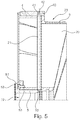
- End piece 2 in more detail at figures 2 and 3 comprises spokes 20 connecting two inner cylindrical parts 201 and outer 200 and arranged equidistantly and two pipes 21 placed symmetrically with respect to the axis xx '.
- the pipes 21 could be made of aluminum, for example.
- the end piece 2 is covered with a composite ring 4 placed and glued on the periphery of said end piece 2. It is open at its center with a hole 22 in which a central ring 5 is placed.
- the spokes 20 are notched and / or bevelled in order to reduce the weight of the end piece 2 as much as possible.
- the end piece 2 has a peripheral recess 23 allowing the positioning and gluing of the outer tube 10.
- the composite ring 4 is provided with a first circumferential groove 41 in its inner part and it is drilled at least one axial hole 40 directed along the axis xx 'and connected to the circumferential groove 41, on one side and to a channel. fluid or air disposed in the outer tube 10 of the other. It is also pierced with a radial nozzle 42.
- the first circumferential groove 40 is closed on three of its sides by the composite ring 4, it could only be closed on two sides, the third being closed by the outer tube 10, without departing from the scope of the invention. .
- the central ring 5 has a second circumferential groove 50 at one of its ends and directed outwards, the other end is provided with a peripheral shoulder 51 pierced with a hole 52 intended to receive a screw 53 for fixing said ring. 5.
- the second circumferential groove 50 is open in order to allow air to pass.
- the second nozzle 3, shown figures 4 and 6 comprises spokes 30 connecting two inner cylindrical parts 301 and outer 300 and arranged equidistantly and a second central ring 6.
- the end piece 3 is machined axially on the periphery to form a recess 31 to have a key 7.
- the bottom of the recess 31 can be peelable in order to allow the height adjustment of the key 7.
- the key 7 is fixed by two screws 7 to the second end piece 3. The key is used to index the clichés.
- the spokes 30 are notched and / or bevelled in order to reduce the weight of the second end piece 3 as much as possible.
- the second end piece 3 has a peripheral recess 32 allowing the positioning and gluing of the other end of the outer tube 10.
- the central ring 6 is connected to the second end piece 3 using screws 60.
- the end pieces 2 and 3 each have a removable ring 5 and 6 which allow the inner tube 11 to be blocked and to be able to be changed by unscrewing the screws 53 and 60 and removing the rings 5 and 6.
- Seals 8 are placed in circular grooves between the rings 5 and 6 and the ends of the inner tube 11 in order to guarantee the seal. We will now describe how the roller according to the invention is mounted.
- the end pieces 2 and 3 are glued to each end of the outer tube 10, the seals 8 are placed inside each end piece 2 and 3, the second ring 6 is positioned and screwed on the second end piece 3, the inner tube 11 is slipped into the end piece 2 and the outer tube 10 until it comes to a stop on the second ring 6 then the ring 5 is fixed on the end piece 2. It is possible to position the ring 5 first, then the inner tube 11 and the second ring 6.
- the first variant illustrated on figure 7 comprises spokes 20 and 30 pierced with holes 202 and 302 in the form of drops of water, other forms of holes could be envisaged. These holes are for example made by machining.
- the spokes 20, 30 are made in the form of a lattice.
- the spokes 20 and 30 of the first and second variants will preferably be produced by additive manufacturing such as 3D printing.
Landscapes
- Engineering & Computer Science (AREA)
- Mechanical Engineering (AREA)
- General Engineering & Computer Science (AREA)
- Rolls And Other Rotary Bodies (AREA)
Claims (18)
- Endstück (2), das dazu bestimmt ist, einen Abstandshalter für eine Walze zu bilden, die aus zwei konzentrischen Rohren (10, 11) mit der Achse xx' besteht und Speichen (20) umfasst, die einen inneren (201) und einen äußeren (200) zylindrischen Teil miteinander verbinden, dadurch gekennzeichnet, dass ein von der Mitte zum Umfang verlaufender Fluidkreislauf eine erste Umfangsnut (50), die in dem inneren zylindrischen Teil (201) angeordnet ist, und eine zweite Umfangsnut (41), die in dem äußeren zylindrischen Teil (200) angeordnet ist, die durch mindestens eine Leitung (22) verbunden sind, umfasst.
- Endstück (2) nach Anspruch 1, dadurch gekennzeichnet, dass das Fluid Druckluft ist.
- Endstück (2) nach Anspruch 1 oder 2, dadurch gekennzeichnet, dass es im inneren zylindrischen Teil (201) einen Ring (5) umfasst.
- Endstück (2) nach einem der vorhergehenden Ansprüche, dadurch gekennzeichnet, dass es mit einem Ring aus elektrisch leitfähigem, nicht-metallischem Material (4) überzogen ist, um einen Verbundring zu bilden.
- Endstück (2) nach einem der vorhergehenden Ansprüche, dadurch gekennzeichnet, dass die Leitung (22) zwischen zwei Speichen (20) angeordnet ist.
- Endstück (2) nach einem der vorhergehenden Ansprüche, dadurch gekennzeichnet, dass es zwei Leitungen (22) umfasst.
- Endstück (2) nach einem der Ansprüche 4 bis 6, dadurch gekennzeichnet, dass der Verbundring (4) eine mit der zweiten Umfangsnut (41) verbundene Axialbohrung (40) umfasst.
- Endstück (2) nach einem der Ansprüche 4 bis 6, dadurch gekennzeichnet, dass die zweite Umfangsnut (41) in dem Verbundring (4) angeordnet ist.
- Endstück (2) nach einem der vorhergehenden Ansprüche, dadurch gekennzeichnet, dass die erste Umfangsnut (50) in einem Mittelring (5) des inneren zylindrischen Teils (201) angeordnet ist.
- Endstück (2) nach einem der vorhergehenden Ansprüche, dadurch gekennzeichnet, dass es aus Verbundwerkstoff hergestellt ist.
- Endstück (2) nach einem der vorhergehenden Ansprüche, dadurch gekennzeichnet, dass die Speichen (20) aus Rippen gebildet sind.
- Endstück (2) nach einem der vorhergehenden Ansprüche, dadurch gekennzeichnet, dass die Speichen (20) aus Gittern gebildet sind.
- Walze (1), bestehend aus zwei konzentrischen Außenrohren (10) und Innenrohren (11) der Achse xx', dadurch gekennzeichnet, dass sie ein Endstück (2) nach einem der vorhergehenden Ansprüche umfasst.
- Walze (1) nach dem vorhergehenden Anspruch, dadurch gekennzeichnet, dass die Rohre (10, 11) aus Verbundwerkstoffen hergestellt sind.
- Walze (1) nach einem der Ansprüche 13 oder 14, dadurch gekennzeichnet, dass das Außenrohr (10) am Endstück (2) befestigt ist.
- Walze (1) nach einem der Ansprüche 13 bis 15, dadurch gekennzeichnet, dass das Innenrohr (11) lösbar am Endstück (2) befestigt ist.
- Walze (1) nach einem der Ansprüche 13 bis 16, dadurch gekennzeichnet, dass das Außenrohr (10) teilweise porös ist.
- Walze (1) nach einem der Ansprüche 13 bis 17, dadurch gekennzeichnet, dass sie ein Endstück (3) mit einem Indexierungsschlüssel (7) umfasst.
Priority Applications (1)
| Application Number | Priority Date | Filing Date | Title |
|---|---|---|---|
| PL18765959T PL3700751T3 (pl) | 2017-10-26 | 2018-08-16 | Końcówka do wałków maszyn przemysłowych |
Applications Claiming Priority (2)
| Application Number | Priority Date | Filing Date | Title |
|---|---|---|---|
| FR1760117A FR3072902B1 (fr) | 2017-10-26 | 2017-10-26 | Embout pour rouleaux de machine industrielle |
| PCT/FR2018/052069 WO2019081823A1 (fr) | 2017-10-26 | 2018-08-16 | Embout pour rouleaux de machine industrielle |
Publications (2)
| Publication Number | Publication Date |
|---|---|
| EP3700751A1 EP3700751A1 (de) | 2020-09-02 |
| EP3700751B1 true EP3700751B1 (de) | 2021-08-11 |
Family
ID=60627880
Family Applications (1)
| Application Number | Title | Priority Date | Filing Date |
|---|---|---|---|
| EP18765959.4A Active EP3700751B1 (de) | 2017-10-26 | 2018-08-16 | Endbeschlag für industrielle maschinenwalzen |
Country Status (6)
| Country | Link |
|---|---|
| US (1) | US11098753B2 (de) |
| EP (1) | EP3700751B1 (de) |
| ES (1) | ES2895970T3 (de) |
| FR (1) | FR3072902B1 (de) |
| PL (1) | PL3700751T3 (de) |
| WO (1) | WO2019081823A1 (de) |
Families Citing this family (1)
| Publication number | Priority date | Publication date | Assignee | Title |
|---|---|---|---|---|
| JP6404517B1 (ja) * | 2018-04-18 | 2018-10-10 | ライズテック株式会社 | 弾性ローラ |
Family Cites Families (19)
| Publication number | Priority date | Publication date | Assignee | Title |
|---|---|---|---|---|
| US3135319A (en) * | 1959-12-24 | 1964-06-02 | Emery B Richards | Leveling roll |
| SE322471B (de) * | 1966-04-28 | 1970-04-06 | Skandinaviska Apparatind | |
| JPS5030955A (de) * | 1973-04-27 | 1975-03-27 | ||
| US4050510A (en) * | 1973-04-27 | 1977-09-27 | Helmuth Theysohn | Calender heating roll |
| US4651643A (en) * | 1985-02-14 | 1987-03-24 | Sidney Katz | Adaptors for use with printing cylinder mandrels |
| DE3521424C1 (de) * | 1985-06-14 | 1986-06-12 | M.A.N.- Roland Druckmaschinen AG, 6050 Offenbach | Farbwalze fuer Druckmaschinen |
| DE9000980U1 (de) * | 1990-01-29 | 1990-05-10 | Schwäbische Hüttenwerke GmbH, 73433 Aalen | Walze für ein Glättwerk oder einen Kalander |
| DE4244812C2 (de) * | 1992-01-25 | 1998-05-28 | Escher Wyss Gmbh | Heiz- oder Kühlwalze |
| DE4300541A1 (de) * | 1993-01-12 | 1994-08-11 | Walzen Irle Gmbh | Temperierbare Walze |
| DE4404922C1 (de) * | 1994-02-16 | 1995-09-28 | Schwaebische Huettenwerke Gmbh | Peripher gebohrte Walze zur Wärmebehandlung von Bahnmaterial |
| US5451198A (en) * | 1994-09-12 | 1995-09-19 | Lancaster; Joseph L. | Roller with replaceable sleeve |
| US5507228A (en) * | 1994-10-03 | 1996-04-16 | Schulz; Werner | Printing cylinder |
| DE19513500C2 (de) * | 1995-04-10 | 1998-05-14 | Schwaebische Huettenwerke Gmbh | Walze mit einstellbarer Form |
| DE19707876C2 (de) * | 1997-02-27 | 2002-09-26 | Voith Paper Patent Gmbh | Walzenanordnung |
| US5904095A (en) * | 1997-03-19 | 1999-05-18 | Meca Of Green Bay, Inc. | Bridge mandrel for flexographic printing presses |
| DE19846677C5 (de) * | 1998-10-09 | 2011-02-10 | Windmöller & Hölscher Kg | Druckwalze mit austauschbarem äußeren Mantel |
| US6276271B1 (en) * | 2000-03-17 | 2001-08-21 | Day International, Inc. | Bridge mandrel for flexographic printing systems |
| US6394943B1 (en) * | 2000-05-19 | 2002-05-28 | Steven Cormier | Image transfer drum for document printer/copier |
| FR2847847B1 (fr) | 2002-11-29 | 2005-01-28 | Epsilon Composite Sarl | Procede de fabrication d'un tube en materiau composite de grande raideur, et tube obtenu |
-
2017
- 2017-10-26 FR FR1760117A patent/FR3072902B1/fr not_active Expired - Fee Related
-
2018
- 2018-08-16 EP EP18765959.4A patent/EP3700751B1/de active Active
- 2018-08-16 PL PL18765959T patent/PL3700751T3/pl unknown
- 2018-08-16 ES ES18765959T patent/ES2895970T3/es active Active
- 2018-08-16 WO PCT/FR2018/052069 patent/WO2019081823A1/fr not_active Ceased
- 2018-08-16 US US16/758,595 patent/US11098753B2/en active Active
Also Published As
| Publication number | Publication date |
|---|---|
| US11098753B2 (en) | 2021-08-24 |
| US20210180646A1 (en) | 2021-06-17 |
| FR3072902B1 (fr) | 2019-11-15 |
| EP3700751A1 (de) | 2020-09-02 |
| FR3072902A1 (fr) | 2019-05-03 |
| PL3700751T3 (pl) | 2022-01-03 |
| ES2895970T3 (es) | 2022-02-23 |
| WO2019081823A1 (fr) | 2019-05-02 |
Similar Documents
| Publication | Publication Date | Title |
|---|---|---|
| CA2913861C (fr) | Dispositif de fixation de deux pieces entre elles | |
| CH316237A (fr) | Palier fluide | |
| EP3785803B1 (de) | Ventil und system zur auftragung eines beschichtungsprodukts, das ein solches ventil umfasst | |
| FR2628024A1 (fr) | Ensemble a buse de coupe par un jet de fluide | |
| FR3023740A3 (fr) | Accessoire pour meche et ensemble a meche | |
| FR2829194A1 (fr) | Ilot de modules pneumatiques | |
| FR2945101A1 (fr) | Nourrice de distribution ou de collecte de fluide et installation de moulage comprenant une telle nourrice | |
| FR3072902B1 (fr) | Embout pour rouleaux de machine industrielle | |
| FR2898328A1 (fr) | Ensemble de fourche de bicyclette. | |
| FR2863188A1 (fr) | Mandrin | |
| FR2940379A1 (fr) | Douille a aiguilles a bague exterieure ayant une face cylindrique exterieure comportant un reseau d'elements en creux | |
| BE1010325A3 (fr) | Carottier. | |
| FR2813558A1 (fr) | Dispositif d'accrochage d'un rayon a la jante d'une roue de bicyclette | |
| FR2843071A1 (fr) | Perfectionnements aux machines d'impression | |
| EP1591714B1 (de) | Vorrichtung zum Schmieren eines Teils in einem Zusammenbau | |
| EP3017210B1 (de) | Bremsvorrichtung mit einem kolben mit vollständiger rückstossfunktion | |
| CH709853A1 (fr) | Pince de serrage. | |
| FR2492022A1 (fr) | Dispositif d'accouplement rigide monte sous pression de fluide | |
| FR2510228A1 (fr) | Systeme de connexion de raccords automatiques pour tuyaux a des dispositifs de distribution de fluides liquides ou gazeux | |
| EP1103694B1 (de) | Einziehungsmechanismus für Rolladenaufwickelrohr | |
| FR2799515A1 (fr) | Systeme a rattrapage de jeu pour fixer deux pieces l'une a l'autre au moyen d'un organe de fixation du type a vis | |
| FR2661852A1 (fr) | Dispositif de serrage oleopneumatique rotatif. | |
| EP1820979B1 (de) | Befestigungsvorrichtung für einen Zapfen auf einem Zylinder, und Zylinder mit einem Zapfen durch diese Vorrichtung befestigt | |
| FR3105339A1 (fr) | Assemblage comportant une canalisation et un regulateur de debit | |
| CN201006677Y (zh) | 可调整培林紧度的花鼓 |
Legal Events
| Date | Code | Title | Description |
|---|---|---|---|
| STAA | Information on the status of an ep patent application or granted ep patent |
Free format text: STATUS: UNKNOWN |
|
| STAA | Information on the status of an ep patent application or granted ep patent |
Free format text: STATUS: THE INTERNATIONAL PUBLICATION HAS BEEN MADE |
|
| PUAI | Public reference made under article 153(3) epc to a published international application that has entered the european phase |
Free format text: ORIGINAL CODE: 0009012 |
|
| STAA | Information on the status of an ep patent application or granted ep patent |
Free format text: STATUS: REQUEST FOR EXAMINATION WAS MADE |
|
| 17P | Request for examination filed |
Effective date: 20200417 |
|
| AK | Designated contracting states |
Kind code of ref document: A1 Designated state(s): AL AT BE BG CH CY CZ DE DK EE ES FI FR GB GR HR HU IE IS IT LI LT LU LV MC MK MT NL NO PL PT RO RS SE SI SK SM TR |
|
| AX | Request for extension of the european patent |
Extension state: BA ME |
|
| DAV | Request for validation of the european patent (deleted) | ||
| DAX | Request for extension of the european patent (deleted) | ||
| GRAP | Despatch of communication of intention to grant a patent |
Free format text: ORIGINAL CODE: EPIDOSNIGR1 |
|
| STAA | Information on the status of an ep patent application or granted ep patent |
Free format text: STATUS: GRANT OF PATENT IS INTENDED |
|
| INTG | Intention to grant announced |
Effective date: 20210421 |
|
| GRAS | Grant fee paid |
Free format text: ORIGINAL CODE: EPIDOSNIGR3 |
|
| GRAA | (expected) grant |
Free format text: ORIGINAL CODE: 0009210 |
|
| STAA | Information on the status of an ep patent application or granted ep patent |
Free format text: STATUS: THE PATENT HAS BEEN GRANTED |
|
| AK | Designated contracting states |
Kind code of ref document: B1 Designated state(s): AL AT BE BG CH CY CZ DE DK EE ES FI FR GB GR HR HU IE IS IT LI LT LU LV MC MK MT NL NO PL PT RO RS SE SI SK SM TR |
|
| REG | Reference to a national code |
Ref country code: CH Ref legal event code: EP |
|
| REG | Reference to a national code |
Ref country code: DE Ref legal event code: R096 Ref document number: 602018021742 Country of ref document: DE |
|
| REG | Reference to a national code |
Ref country code: IE Ref legal event code: FG4D Free format text: LANGUAGE OF EP DOCUMENT: FRENCH Ref country code: AT Ref legal event code: REF Ref document number: 1418983 Country of ref document: AT Kind code of ref document: T Effective date: 20210915 |
|
| REG | Reference to a national code |
Ref country code: RO Ref legal event code: EPE |
|
| REG | Reference to a national code |
Ref country code: NL Ref legal event code: FP |
|
| REG | Reference to a national code |
Ref country code: LT Ref legal event code: MG9D |
|
| REG | Reference to a national code |
Ref country code: AT Ref legal event code: MK05 Ref document number: 1418983 Country of ref document: AT Kind code of ref document: T Effective date: 20210811 |
|
| PG25 | Lapsed in a contracting state [announced via postgrant information from national office to epo] |
Ref country code: HR Free format text: LAPSE BECAUSE OF FAILURE TO SUBMIT A TRANSLATION OF THE DESCRIPTION OR TO PAY THE FEE WITHIN THE PRESCRIBED TIME-LIMIT Effective date: 20210811 Ref country code: FI Free format text: LAPSE BECAUSE OF FAILURE TO SUBMIT A TRANSLATION OF THE DESCRIPTION OR TO PAY THE FEE WITHIN THE PRESCRIBED TIME-LIMIT Effective date: 20210811 Ref country code: RS Free format text: LAPSE BECAUSE OF FAILURE TO SUBMIT A TRANSLATION OF THE DESCRIPTION OR TO PAY THE FEE WITHIN THE PRESCRIBED TIME-LIMIT Effective date: 20210811 Ref country code: SE Free format text: LAPSE BECAUSE OF FAILURE TO SUBMIT A TRANSLATION OF THE DESCRIPTION OR TO PAY THE FEE WITHIN THE PRESCRIBED TIME-LIMIT Effective date: 20210811 Ref country code: LT Free format text: LAPSE BECAUSE OF FAILURE TO SUBMIT A TRANSLATION OF THE DESCRIPTION OR TO PAY THE FEE WITHIN THE PRESCRIBED TIME-LIMIT Effective date: 20210811 Ref country code: BG Free format text: LAPSE BECAUSE OF FAILURE TO SUBMIT A TRANSLATION OF THE DESCRIPTION OR TO PAY THE FEE WITHIN THE PRESCRIBED TIME-LIMIT Effective date: 20211111 Ref country code: AT Free format text: LAPSE BECAUSE OF FAILURE TO SUBMIT A TRANSLATION OF THE DESCRIPTION OR TO PAY THE FEE WITHIN THE PRESCRIBED TIME-LIMIT Effective date: 20210811 Ref country code: PT Free format text: LAPSE BECAUSE OF FAILURE TO SUBMIT A TRANSLATION OF THE DESCRIPTION OR TO PAY THE FEE WITHIN THE PRESCRIBED TIME-LIMIT Effective date: 20211213 Ref country code: NO Free format text: LAPSE BECAUSE OF FAILURE TO SUBMIT A TRANSLATION OF THE DESCRIPTION OR TO PAY THE FEE WITHIN THE PRESCRIBED TIME-LIMIT Effective date: 20211111 |
|
| REG | Reference to a national code |
Ref country code: ES Ref legal event code: FG2A Ref document number: 2895970 Country of ref document: ES Kind code of ref document: T3 Effective date: 20220223 |
|
| PG25 | Lapsed in a contracting state [announced via postgrant information from national office to epo] |
Ref country code: LV Free format text: LAPSE BECAUSE OF FAILURE TO SUBMIT A TRANSLATION OF THE DESCRIPTION OR TO PAY THE FEE WITHIN THE PRESCRIBED TIME-LIMIT Effective date: 20210811 Ref country code: GR Free format text: LAPSE BECAUSE OF FAILURE TO SUBMIT A TRANSLATION OF THE DESCRIPTION OR TO PAY THE FEE WITHIN THE PRESCRIBED TIME-LIMIT Effective date: 20211112 |
|
| REG | Reference to a national code |
Ref country code: CH Ref legal event code: PL |
|
| REG | Reference to a national code |
Ref country code: BE Ref legal event code: MM Effective date: 20210831 |
|
| PG25 | Lapsed in a contracting state [announced via postgrant information from national office to epo] |
Ref country code: LI Free format text: LAPSE BECAUSE OF NON-PAYMENT OF DUE FEES Effective date: 20210831 Ref country code: DK Free format text: LAPSE BECAUSE OF FAILURE TO SUBMIT A TRANSLATION OF THE DESCRIPTION OR TO PAY THE FEE WITHIN THE PRESCRIBED TIME-LIMIT Effective date: 20210811 Ref country code: CH Free format text: LAPSE BECAUSE OF NON-PAYMENT OF DUE FEES Effective date: 20210831 |
|
| REG | Reference to a national code |
Ref country code: DE Ref legal event code: R097 Ref document number: 602018021742 Country of ref document: DE |
|
| PG25 | Lapsed in a contracting state [announced via postgrant information from national office to epo] |
Ref country code: SM Free format text: LAPSE BECAUSE OF FAILURE TO SUBMIT A TRANSLATION OF THE DESCRIPTION OR TO PAY THE FEE WITHIN THE PRESCRIBED TIME-LIMIT Effective date: 20210811 Ref country code: SK Free format text: LAPSE BECAUSE OF FAILURE TO SUBMIT A TRANSLATION OF THE DESCRIPTION OR TO PAY THE FEE WITHIN THE PRESCRIBED TIME-LIMIT Effective date: 20210811 Ref country code: MC Free format text: LAPSE BECAUSE OF FAILURE TO SUBMIT A TRANSLATION OF THE DESCRIPTION OR TO PAY THE FEE WITHIN THE PRESCRIBED TIME-LIMIT Effective date: 20210811 Ref country code: LU Free format text: LAPSE BECAUSE OF NON-PAYMENT OF DUE FEES Effective date: 20210816 Ref country code: EE Free format text: LAPSE BECAUSE OF FAILURE TO SUBMIT A TRANSLATION OF THE DESCRIPTION OR TO PAY THE FEE WITHIN THE PRESCRIBED TIME-LIMIT Effective date: 20210811 Ref country code: CZ Free format text: LAPSE BECAUSE OF FAILURE TO SUBMIT A TRANSLATION OF THE DESCRIPTION OR TO PAY THE FEE WITHIN THE PRESCRIBED TIME-LIMIT Effective date: 20210811 Ref country code: AL Free format text: LAPSE BECAUSE OF FAILURE TO SUBMIT A TRANSLATION OF THE DESCRIPTION OR TO PAY THE FEE WITHIN THE PRESCRIBED TIME-LIMIT Effective date: 20210811 |
|
| PLBE | No opposition filed within time limit |
Free format text: ORIGINAL CODE: 0009261 |
|
| STAA | Information on the status of an ep patent application or granted ep patent |
Free format text: STATUS: NO OPPOSITION FILED WITHIN TIME LIMIT |
|
| 26N | No opposition filed |
Effective date: 20220512 |
|
| PG25 | Lapsed in a contracting state [announced via postgrant information from national office to epo] |
Ref country code: IE Free format text: LAPSE BECAUSE OF NON-PAYMENT OF DUE FEES Effective date: 20210816 Ref country code: BE Free format text: LAPSE BECAUSE OF NON-PAYMENT OF DUE FEES Effective date: 20210831 |
|
| PG25 | Lapsed in a contracting state [announced via postgrant information from national office to epo] |
Ref country code: SI Free format text: LAPSE BECAUSE OF FAILURE TO SUBMIT A TRANSLATION OF THE DESCRIPTION OR TO PAY THE FEE WITHIN THE PRESCRIBED TIME-LIMIT Effective date: 20210811 |
|
| PGFP | Annual fee paid to national office [announced via postgrant information from national office to epo] |
Ref country code: NL Payment date: 20220822 Year of fee payment: 5 |
|
| PGFP | Annual fee paid to national office [announced via postgrant information from national office to epo] |
Ref country code: RO Payment date: 20220808 Year of fee payment: 5 Ref country code: GB Payment date: 20220824 Year of fee payment: 5 Ref country code: ES Payment date: 20220919 Year of fee payment: 5 |
|
| PGFP | Annual fee paid to national office [announced via postgrant information from national office to epo] |
Ref country code: PL Payment date: 20220808 Year of fee payment: 5 |
|
| P01 | Opt-out of the competence of the unified patent court (upc) registered |
Effective date: 20230516 |
|
| PG25 | Lapsed in a contracting state [announced via postgrant information from national office to epo] |
Ref country code: CY Free format text: LAPSE BECAUSE OF FAILURE TO SUBMIT A TRANSLATION OF THE DESCRIPTION OR TO PAY THE FEE WITHIN THE PRESCRIBED TIME-LIMIT Effective date: 20210811 |
|
| PG25 | Lapsed in a contracting state [announced via postgrant information from national office to epo] |
Ref country code: HU Free format text: LAPSE BECAUSE OF FAILURE TO SUBMIT A TRANSLATION OF THE DESCRIPTION OR TO PAY THE FEE WITHIN THE PRESCRIBED TIME-LIMIT; INVALID AB INITIO Effective date: 20180816 |
|
| REG | Reference to a national code |
Ref country code: NL Ref legal event code: MM Effective date: 20230901 |
|
| GBPC | Gb: european patent ceased through non-payment of renewal fee |
Effective date: 20230816 |
|
| PG25 | Lapsed in a contracting state [announced via postgrant information from national office to epo] |
Ref country code: RO Free format text: LAPSE BECAUSE OF NON-PAYMENT OF DUE FEES Effective date: 20230816 Ref country code: MK Free format text: LAPSE BECAUSE OF FAILURE TO SUBMIT A TRANSLATION OF THE DESCRIPTION OR TO PAY THE FEE WITHIN THE PRESCRIBED TIME-LIMIT Effective date: 20210811 |
|
| PG25 | Lapsed in a contracting state [announced via postgrant information from national office to epo] |
Ref country code: NL Free format text: LAPSE BECAUSE OF NON-PAYMENT OF DUE FEES Effective date: 20230901 |
|
| PG25 | Lapsed in a contracting state [announced via postgrant information from national office to epo] |
Ref country code: NL Free format text: LAPSE BECAUSE OF NON-PAYMENT OF DUE FEES Effective date: 20230901 |
|
| PG25 | Lapsed in a contracting state [announced via postgrant information from national office to epo] |
Ref country code: TR Free format text: LAPSE BECAUSE OF FAILURE TO SUBMIT A TRANSLATION OF THE DESCRIPTION OR TO PAY THE FEE WITHIN THE PRESCRIBED TIME-LIMIT Effective date: 20210811 |
|
| PG25 | Lapsed in a contracting state [announced via postgrant information from national office to epo] |
Ref country code: GB Free format text: LAPSE BECAUSE OF NON-PAYMENT OF DUE FEES Effective date: 20230816 |
|
| PG25 | Lapsed in a contracting state [announced via postgrant information from national office to epo] |
Ref country code: GB Free format text: LAPSE BECAUSE OF NON-PAYMENT OF DUE FEES Effective date: 20230816 |
|
| REG | Reference to a national code |
Ref country code: ES Ref legal event code: FD2A Effective date: 20240927 |
|
| PG25 | Lapsed in a contracting state [announced via postgrant information from national office to epo] |
Ref country code: MT Free format text: LAPSE BECAUSE OF FAILURE TO SUBMIT A TRANSLATION OF THE DESCRIPTION OR TO PAY THE FEE WITHIN THE PRESCRIBED TIME-LIMIT Effective date: 20210811 |
|
| PG25 | Lapsed in a contracting state [announced via postgrant information from national office to epo] |
Ref country code: ES Free format text: LAPSE BECAUSE OF NON-PAYMENT OF DUE FEES Effective date: 20230817 |
|
| PG25 | Lapsed in a contracting state [announced via postgrant information from national office to epo] |
Ref country code: ES Free format text: LAPSE BECAUSE OF NON-PAYMENT OF DUE FEES Effective date: 20230817 |
|
| PG25 | Lapsed in a contracting state [announced via postgrant information from national office to epo] |
Ref country code: PL Free format text: LAPSE BECAUSE OF NON-PAYMENT OF DUE FEES Effective date: 20230816 |
|
| PG25 | Lapsed in a contracting state [announced via postgrant information from national office to epo] |
Ref country code: PL Free format text: LAPSE BECAUSE OF NON-PAYMENT OF DUE FEES Effective date: 20230816 |
|
| PGFP | Annual fee paid to national office [announced via postgrant information from national office to epo] |
Ref country code: DE Payment date: 20250819 Year of fee payment: 8 |
|
| PGFP | Annual fee paid to national office [announced via postgrant information from national office to epo] |
Ref country code: IT Payment date: 20250829 Year of fee payment: 8 |
|
| PGFP | Annual fee paid to national office [announced via postgrant information from national office to epo] |
Ref country code: FR Payment date: 20250821 Year of fee payment: 8 |