EP3700720B1 - Greif- oder spannvorrichtung, zugehöriger funktionsmechanismus sowie zugehöriger baukasten - Google Patents
Greif- oder spannvorrichtung, zugehöriger funktionsmechanismus sowie zugehöriger baukasten Download PDFInfo
- Publication number
- EP3700720B1 EP3700720B1 EP18786311.3A EP18786311A EP3700720B1 EP 3700720 B1 EP3700720 B1 EP 3700720B1 EP 18786311 A EP18786311 A EP 18786311A EP 3700720 B1 EP3700720 B1 EP 3700720B1
- Authority
- EP
- European Patent Office
- Prior art keywords
- gripping
- coupling
- clamping device
- coupling member
- unit
- Prior art date
- Legal status (The legal status is an assumption and is not a legal conclusion. Google has not performed a legal analysis and makes no representation as to the accuracy of the status listed.)
- Active
Links
Images


Classifications
-
- B—PERFORMING OPERATIONS; TRANSPORTING
- B25—HAND TOOLS; PORTABLE POWER-DRIVEN TOOLS; MANIPULATORS
- B25J—MANIPULATORS; CHAMBERS PROVIDED WITH MANIPULATION DEVICES
- B25J15/00—Gripping heads and other end effectors
- B25J15/02—Gripping heads and other end effectors servo-actuated
- B25J15/0253—Gripping heads and other end effectors servo-actuated comprising parallel grippers
- B25J15/026—Gripping heads and other end effectors servo-actuated comprising parallel grippers actuated by gears
-
- B—PERFORMING OPERATIONS; TRANSPORTING
- B25—HAND TOOLS; PORTABLE POWER-DRIVEN TOOLS; MANIPULATORS
- B25B—TOOLS OR BENCH DEVICES NOT OTHERWISE PROVIDED FOR, FOR FASTENING, CONNECTING, DISENGAGING, OR HOLDING
- B25B1/00—Vices
- B25B1/02—Vices with sliding jaws
-
- B—PERFORMING OPERATIONS; TRANSPORTING
- B25—HAND TOOLS; PORTABLE POWER-DRIVEN TOOLS; MANIPULATORS
- B25B—TOOLS OR BENCH DEVICES NOT OTHERWISE PROVIDED FOR, FOR FASTENING, CONNECTING, DISENGAGING, OR HOLDING
- B25B1/00—Vices
- B25B1/06—Arrangements for positively actuating jaws
- B25B1/18—Arrangements for positively actuating jaws motor driven, e.g. with fluid drive, with or without provision for manual actuation
-
- B—PERFORMING OPERATIONS; TRANSPORTING
- B25—HAND TOOLS; PORTABLE POWER-DRIVEN TOOLS; MANIPULATORS
- B25B—TOOLS OR BENCH DEVICES NOT OTHERWISE PROVIDED FOR, FOR FASTENING, CONNECTING, DISENGAGING, OR HOLDING
- B25B5/00—Clamps
- B25B5/02—Clamps with sliding jaws
-
- B—PERFORMING OPERATIONS; TRANSPORTING
- B25—HAND TOOLS; PORTABLE POWER-DRIVEN TOOLS; MANIPULATORS
- B25B—TOOLS OR BENCH DEVICES NOT OTHERWISE PROVIDED FOR, FOR FASTENING, CONNECTING, DISENGAGING, OR HOLDING
- B25B5/00—Clamps
- B25B5/06—Arrangements for positively actuating jaws
- B25B5/061—Arrangements for positively actuating jaws with fluid drive
-
- B—PERFORMING OPERATIONS; TRANSPORTING
- B25—HAND TOOLS; PORTABLE POWER-DRIVEN TOOLS; MANIPULATORS
- B25B—TOOLS OR BENCH DEVICES NOT OTHERWISE PROVIDED FOR, FOR FASTENING, CONNECTING, DISENGAGING, OR HOLDING
- B25B5/00—Clamps
- B25B5/16—Details, e.g. jaws, jaw attachments
- B25B5/166—Slideways; Guiding and/or blocking means for jaws thereon
-
- B—PERFORMING OPERATIONS; TRANSPORTING
- B25—HAND TOOLS; PORTABLE POWER-DRIVEN TOOLS; MANIPULATORS
- B25J—MANIPULATORS; CHAMBERS PROVIDED WITH MANIPULATION DEVICES
- B25J19/00—Accessories fitted to manipulators, e.g. for monitoring, for viewing; Safety devices combined with or specially adapted for use in connection with manipulators
- B25J19/0004—Braking devices
Definitions
- the invention relates to a gripping or clamping device comprising a base housing, at least one base jaw, and preferably two base jaws movable toward and away from each other, wherein the at least one base jaw is coupled in motion to at least one working piston.
- the working piston is movable, in particular, within a working cylinder and defines a working pressure chamber, so that the base jaws are moved when pressure is applied to the working pressure chamber.
- the connecting section is formed by a cylindrical portion of the coupling link, which is completely located within the housing.
- a split bushing is provided around the cylindrical portion to secure the coupling link.
- a gripping or clamping device having the features of patent claim 1. Consequently, it is particularly provided that the free end of the coupling member forms the connecting section for coupling the movement of the coupling member to the functional mechanism, and that the base housing has an opening such that the connecting section is accessible from outside the base housing.
- the functional mechanism is provided for manipulating movement and/or for determining the position of the base jaw.
- the base housing has a receptacle for the coupling member such that the coupling member is arranged interchangeably on or in the base housing.
- the coupling member can be a drive member of a drive, a braking member of a braking unit, a locking member of a locking unit, a measuring member of a measuring unit, a Synchronization element of a synchronization unit or a control/regulation element of a control and/or regulation unit.
- the movement of the working pistons, and thus the movement of the base jaws can be manipulated and/or position-determined.
- This also includes the possibility of synchronizing and/or controlling the base jaw with other components via the functional mechanism.
- Manipulation can be achieved, in particular, by additional driving, additional braking, and/or by locking the coupling element, and thus the base jaws, by applying a corresponding force to the connecting section.
- Such a gripping or clamping device can therefore be used universally and, depending on the requirements placed on the device, can be provided with a suitable functional mechanism via the connecting section, thus allowing the gripping or clamping device to be used very flexibly. Because only a corresponding functional mechanism needs to be provided, the gripping or clamping device according to the invention can be used in a wide variety of applications with different functional mechanisms.
- the connecting section provides a drive profile for the rotary coupling of a rotary member on the functional mechanism side.
- the rotary member of the functional mechanism can then interact, in particular in a form-fitting manner, with the drive profile for the rotary coupling.
- the drive profile is arranged on the free end face of the coupling link or around the free end face of the coupling link.
- the rotary link can then be plugged onto the coupling link or inserted into it.
- the free end face of the connecting section is at least largely flush with the surface of the housing.
- each working piston having a coupling section, and wherein the coupling link that is movement-coupled to the two coupling sections is provided between the two coupling sections.
- the coupling link By providing the coupling link, a synchronous movement of the two base jaws can be achieved. Nevertheless, comparatively high gripping forces can be provided because both working pistons can be subjected to a working pressure. In addition, different gripping forces can also be achieved, for example if only one working piston is subjected to the working pressure.
- the movement coupling between the coupling member and the coupling section of the two working pistons can in particular This can be realized via a positive coupling, for example in the form of a pinion provided on the coupling element that interacts with teeth provided on the coupling section.
- a positive coupling for example in the form of a pinion provided on the coupling element that interacts with teeth provided on the coupling section.
- Another type of motion coupling is also conceivable, for example, a frictional or force-locking coupling, or a coupling that can achieve torque limitation.
- the connecting section provides a suitable drive profile, via which the respective functional mechanism can be coupled to the coupling element.
- the drive profile can be implemented, for example, as a pinion, an edged or round profile, for example, as a hexagon socket or hexalobular socket, as an external hexagon profile, a slotted or Phillips profile, or the like.
- the connecting section can be arranged within the housing or protrude from the housing.
- An arrangement within the housing has the advantage that such a gripping or clamping device can also be operated without a connected functional mechanism, and without requiring additional installation space.
- the connecting section can also protrude from the housing, so that the functional mechanism can be easily connected to the connecting section.
- the bearing bush can in particular comprise a shaft section of the coupling link.
- the bearing bushing which is attached to the base housing, for example, by means of screws, can be loosened and removed.
- the coupling link can also be designed such that, after removing the bearing bushing, it can be removed from the base housing along its axis of rotation.
- the coupling member may further comprise an active portion that interacts with the coupling portion and at least one shaft portion with the connecting portion.
- the active portion may, for example, comprise a toothing that interacts with a mating toothing provided on the coupling portion.
- the shaft portion may, for example, serve to pivotally support the coupling member, in particular to accommodate a bearing bush.
- the connecting portion is preferably arranged in the region of the free end of the shaft portion or in the region of the shaft portion that protrudes from the base housing.
- an elastic preload element is provided between the coupling section and a driver provided on the respective base jaw.
- the two working pistons preferably have one or two pressurizable working piston surfaces and each have a working piston rod, wherein the respective coupling section is provided on the respective working piston rod.
- the coupling sections provided on the working piston rods can be either integral with the working piston rod or be designed as a separate component. If the coupling sections are designed as separate components, it is advantageous if the respective working piston rod has a recess to accommodate the respective coupling section. This allows the coupling section to be arranged in a small installation space. Furthermore, forces can be transmitted reliably.
- the respective coupling sections can each have an active section that interacts with the coupling member and extends into an area between the coupling member and the coupling rod.
- the coupling rod can, for example, have a quarter-circle cross-section, on which the coupling section is arranged.
- the active section then preferably extends between the working piston rod and the coupling member, or its active section.
- a gripping or clamping unit which comprises a gripping or clamping device according to the invention and which comprises a functional mechanism which is coupled to the gripping or clamping device via the connecting section of the gripping or clamping device.
- the functional mechanism can preferably be arranged in a separate attachment housing, which can be attached to or secured to the base housing. This has the advantage that different functional mechanisms can be stored in different attachment housings, and that the appropriate functional mechanism can be used with the gripping or clamping device as needed.
- the clamping unit according to the invention can provide a drive unit, a braking unit, a fixing unit, a measuring unit, a synchronization unit and/or a regulating and/or control unit as a functional mechanism.
- a modular system comprising a gripping or clamping device according to the invention as well as various coupling elements with connecting sections for connecting different functional mechanisms and/or different functional mechanisms for arranging the gripping or clamping device according to the invention.
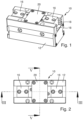
- a gripping device 10 is shown with a base housing 12 in which two working pistons 14 are arranged to be movable in a working cylinder 15, each working piston 14 being coupled in motion to a base jaw 16.
- the base housing 12 has multi-tooth guides 18 for guiding the base jaws 16.
- a cover plate 20 is attached to the base housing 12 in the central region between the base jaws 16.
- the two working pistons 14 can be moved parallel to one another along the axes 22.
- the working pistons 14 each further comprise a working piston rod 24, to which a coupling section 26 is fastened.
- the coupling sections 26 each have an active section 28 in the form of a linear toothing on the sides facing one another.
- the two coupling sections 26 interact via the toothing 28 with a coupling member 30, which has an active section 32 in the form of a pinion.
- the pinion 32 meshes with the linear toothing 28 of the coupling sections 26.
- the coupling member 30 is arranged to rotate about a rotation axis 34 and synchronizes the movement of the two working pistons 14 or their working piston rods 24 and thus the movement of the base jaws 16.
- the coupling member 30 has a connecting section 36 which is flush with the outside of the base housing 12 and is accessible from outside the base housing 12.
- the connecting section 36 is arranged on the free end face of the coupling member 30 and comprises a driving profile 37.
- the driving profile 37 can be designed as a hexagon socket or a hexagon socket, via which the coupling member 30 can be connected to a functional mechanism, as is shown, for example, in Figure 7 shown, can be connected.
- the base housing 12 further has an opening 41 such that the connection section 36 is accessible from outside the base housing 12.
- bearing bush 38 is provided, which is fastened to the base housing 12 by means of fastening screws 40 in a receptacle 39 provided in the opening 41. By loosening the screws 40, the bearing bush 38 and the coupling member 30 can be removed from the receptacle 39.
- a differently designed coupling member 30 with a correspondingly designed connecting section 36 can be used.
- the working piston rods 24 have a recess 42 within which the coupling sections 26 are arranged.
- Figure 5 shows that the active section 28 of the coupling sections 26 lies in a region between the respective working piston rod 24 and the pinion 32 of the coupling member 30. In this region, the working piston rods 24 have a quarter-circular cross-section.
- a driver 44 is provided on each of the base jaws 16, which is coupled in movement to the respective coupling section 26.
- the drivers 44 are Figure 6 shown fastening screws rigidly connected to the base jaws 16.
- an elastic element 46 is provided, with which the gripping force can be maintained or which provides a preload force when gripping a component.
- the working pressure chambers 50, 52 delimited by the working pistons 14 are alternately subjected to working pressure, whereby when the working pressure chambers 50 are pressurized, the base jaws 16 are moved towards one another and when the working pressure chambers 52 are pressurized, the base jaws 16 are moved away from one another.
- a drive unit can be used, for example, which drives the coupling member 30 and thus the base jaws 16 which are coupled in movement with the coupling member 30. It is also conceivable to provide a braking unit with which the movement of the coupling member 30, and thus the movement of the base jaws 16, is braked. It is also conceivable to provide a fixing unit with which the coupling member 30, and thus the base jaws 16, can be fixed in a position. It is also conceivable to provide a measuring unit with which the angle of rotation of the coupling member 30, and thus the position of the base jaws 16, can be measured.
- a synchronization unit with which the movement of the coupling member 30, and thus the movement of the base jaws 16, is synchronized with other functional components.
- a regulating and/or control unit can also be provided which, depending on the rotational position of the coupling member 30, a torque acting on the coupling member 30 and/or a force acting on the coupling member, controls other functional components accordingly.
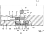
- a functional mechanism 60 is shown, which is housed in a housing 62.
- the housing 62 can be connected to the Figure 7
- the functional mechanism 60 is a positioning drive 64 with a fixing unit 66.
- the positioning drive 64 comprises a positioning cylinder 68 and a positioning piston 70 arranged therein so as to be movable.
- the positioning piston 70 limits a Positioning pressure chamber 72.
- a piston rod 74 is provided on the positioning piston 70, which has a toothed portion 76.
- the pressure-effective area of the positioning piston 70 is smaller than the pressure-effective area of the working pistons.
- a coupling member 30 which has a pinion 32 at its upper, free end, which is intended to be connected to the coupling sections 26 of the gripping device 10, as shown in the Figures 1 to 6 shown.
- the coupling member 30 also provides a wide pinion 78, which cooperates with the toothed portion 76 of the piston rod 74.
- the free end face of the connecting portion 36 protrudes above the surface of the housing (12).
- the locking unit 66 can be used to lock the coupling member 30 and thus also the base jaws 16.
- a flange section 80 designed as a brake disc is provided at the end of the coupling member 30 facing away from the pinion 78.
- the flange section 80 is axially displaceable in the axial direction on the coupling member 30 or on a cylinder section 82 provided for this purpose.
- the flange section 80 is rotationally coupled via a spring 84 provided on the cylinder section 82, which cooperates with a receiving groove 86 provided on the flange section 80.
- the flange section 80 is axially displaceable in a locking cylinder 88, wherein the flange section 80 defines a locking pressure chamber 90.
- a spring element 92 in the form of a disc spring is provided, which presses the flange section 82 against a clamping element 94 in the form of a brake disc and, when the pressure is released, fixing pressure chamber 90.
- An axial bearing 96 is provided on the side of the disc spring 92 facing away from the flange section 80.
- the flange section 80 When pressure is applied to the locking pressure chamber 90, the flange section 80 is loaded toward the disc spring 92, thereby compressing the disc spring 92. Due to the provision of the axial bearing 96, the flange section 80 can be easily rotated about the axis 34 even when the disc spring 92 is compressed. Consequently, when pressure is applied to the locking pressure chamber 90, the locking unit 66 is released, and the coupling member 30 can be rotated about its axis of rotation 34.
- the gripping device 10 works together with the functional mechanism 60 as follows: First, the base jaws 16 are moved into the gripping position by applying pressure to the positioning pressure chamber 72. The positioning force acting on the jaw 16 or on the top jaws provided on the base jaws 16 does not exceed a permissible limit force due to the selection of a correspondingly large pressure-effective area of the positioning piston 70.
- the limit force can be, for example, 140 Newtons.
- the corresponding working pressure chamber 50, 52 is pressurized with working pressure; due to the larger pressure-effective area of the pistons 14, the actual gripping force acts on the jaws 16, which can be many times higher than the positioning force.
- a switching of the working pressure from the positioning pressure chamber 72 to the working pressure chamber 50 or 52 can be carried out, for example, via a switching device, wherein sensors are provided which then cause a switchover when it is determined that the base jaws 16 reach their gripping positions.
- the locking unit 66 can release the base jaws 16, which is achieved by applying working pressure to the locking pressure chamber 90.
- the jaws 16 can be retracted by applying pressure to a pressure chamber opposite the positioning pressure chamber 72 or to a correspondingly provided spring element.
- a gripping unit By combining the gripping device 10 according to the Figures 1 to 6 and the positioning drive 64 provided in the attachment housing 62 with the fixing unit 66, a gripping unit can be provided which is suitable for human-machine collaboration.
Landscapes
- Engineering & Computer Science (AREA)
- Mechanical Engineering (AREA)
- Robotics (AREA)
- Manipulator (AREA)
- Braking Arrangements (AREA)
Description
- Die Erfindung betrifft eine Greif- oder Spannvorrichtung mit einem Grundgehäuse, mit wenigstens einer Grundbacke und mit vorzugsweise zwei aufeinander zu und voneinander weg verfahrbaren Grundbacken, wobei die wenigstens eine Grundbacke mit wenigstens einem Arbeitskolben bewegungsgekoppelt ist. Der Arbeitskolben ist dabei insbesondere in einem Arbeitszylinder verfahrbar und begrenzt einen Arbeitsdruckraum, so dass bei Druckbeaufschlagung des Arbeitsdruckraums die Grundbacken verfahren werden.
- Aus der
GB 2 147 268 A - Greif- oder Spannvorrichtungen ohne eine Brems- und/oder Festsetzeinheit sind beispielsweise bekannt aus der
DE 100 13 022 C2 oderDE 101 38 685 C1 . - Ferner ist aus der
DE 2011 084 177 A1 bekannt, ein Dämpfungselement zwischen dem Antrieb der Greifbacke und der Greifbacke vorzusehen. Aus derDE 10 2013 211 528 A1 ist bekannt, ein elastisches Federelement zur Greifkrafterhaltung vorzusehen. - Der
EP 2 581 170 A2 ist eine Greifvorrichtung mit einer Bremseinheit bekannt, wobei die Bremseinheit außerhalb eines Grundgehäuse angeordnet ist. Die Bremseinheit wird dabei auf einen Schaft, der über Ritzel mit Zahnstangen zusammenwirkt, wobei die Zahnstangen an einem verfahrbaren Zylinder angeordnet sind. - Der Erfindung liegt die Aufgabe zugrunde, eine Greif- oder Spanneinheit bereitzustellen, mit der auf einfache Art und Weise ein präzises und sicheres Greifen sowie ein universeller Einsatz möglich ist.
- Diese Aufgabe wird gelöst durch eine Greif- oder Spannvorrichtung mit den Merkmalen des Patentanspruchs 1. Folglich ist insbesondere vorgesehen, dass das freie Ende des Koppelglieds den Anschlussabschnitt zur Bewegungskopplung des Koppelglieds mit dem Funktionsmechanismus bildet und dass das Grundgehäuse eine Öffnung derart aufweist, dass der Anschlussabschnitt von außerhalb des Grundgehäuses zugänglich ist. Der Funktionsmechanismus ist dabei zur Bewegungsmanipulation und/oder zur Lagebestimmung der Grundbacke vorgesehen. Ferner ist vorgesehen, dass das Grundgehäuse eine Aufnahme für das Koppelglied derart aufweist, dass das Koppelglied austauschbar am oder im Grundgehäuse angeordnet ist. Dies hat den Vorteil, dass das Koppelglied, je nach vorzusehendem Funktionsmechanismus, unterschiedlich ausgebildet sein kann und auf einfache Art und Weise ausgetauscht werden kann. Es können folglich unterschiedliche Koppelglieder Verwendung finden. Denkbar ist, dass das Koppelglied ein Antriebsglied eines Antriebs, ein Bremsglied einer Bremseinheit, ein Festsetzglied einer Festsetzeinheit, ein Messglied einer Messeinheit, ein Synchronisationsglied einer Synchronisationseinheit oder ein Steuer-/Regelglied einer Steuer- und/oder Regeleinheit ist.
- Durch Vorsehen des Anschlussabschnitts kann folglich die Bewegung der Arbeitskolben, und damit die Bewegung der Grundbacken, insbesondere bewegungsmanipuliert und/oder lagebestimmt werden. Davon umfasst ist auch, dass Grundbacke über den Funktionsmechanismus mit anderen Komponenten synchronisiert und/oder geregelt oder angesteuert werden kann. Eine Manipulation kann insbesondere durch ein zusätzliches Antreiben, zusätzliches Abbremsen und/oder durch ein Festsetzen des Koppelgliedes, und damit der Grundbacken, über eine entsprechende Krafteinwirkung auf den Anschlussabschnitt erfolgen.
- Eine derartige Greif- oder Spannvorrichtung kann folglich universell eingesetzt werden und je nach an die Vorrichtung gestellten Anforderungen über den Anschlussabschnitt mit einem geeigneten Funktionsmechanismus versehen werden, wodurch die Greif- oder Spannvorrichtung sehr flexibel einsetzbar ist. Dadurch, dass lediglich ein entsprechender Funktionsmechanismus bereitgestellt werden muss, kann die erfindungsgemäße Greif- oder Spannvorrichtung in unterschiedlichsten Anwendungen mit unterschiedlichen Funktionsmechanismen zum Einsatz kommen.
- Ferner ist vorteilhaft, wenn der Anschlussabschnitt ein Mitnahmeprofil zur Drehkopplung eines funktionsmechanismusseitigen Drehglieds vorsieht. Das Drehglied des Funktionsmechanismus kann dann zur Drehkopplung insbesondere formschlüssig mit dem Mitnahmeprofil zusammenwirken.
- Dabei ist denkbar, dass das Mitnahmeprofil an der freien Stirnseite des Koppelglieds oder um die freie Stirnseite des Koppelglieds herum angeordnet ist. Das Drehglied kann dann insbesondere auf das Koppelglied aufgesteckt oder in dieses hineingesteckt werden.
- Um ein günstiges Zusammenwirken des Anschlussabschnitts mit dem Drehglied des Funktionsmechanismus zu ermöglichen, ist es vorteilhaft, wenn die freie Stirnseite des Anschlussabschnitts wenigstens weitgehend bündig mit der Oberfläche des Gehäuses abschließt.
- Ferner ist vorteilhaft, wenn zwei parallel zueinander verlagerbare Arbeitskolben vorgesehen sind, wobei jeder Arbeitskolben einen Koppelabschnitt aufweist, und wobei zwischen den beiden Koppelabschnitten das mit den beiden Koppelabschnitten bewegungsgekoppelte Koppelglied vorgesehen ist. Durch vorsehen des Koppelglieds kann eine synchrone Bewegung der beiden Grundbacken realisiert werden. Dennoch können vergleichsweise hohe Greifkräfte bereitgestellt werden, da beide Arbeitskolben mit einem Arbeitsdruck beaufschlagt werden können. Zudem können auch unterschiedliche Greifkräfte realisiert werden, beispielsweise dann, wenn nur ein Arbeitskolben mit dem Arbeitsdruck beaufschlagt wird. Durch Vorsehen des Koppelglieds zwischen den beiden Arbeitskolben kann eine Manipulation der Kolben zeitgleich und/oder eine Lagebestimmung beider Kolben, und damit beider Grundbacken über lediglich das eine Koppelglied erreicht werden.
- Die Bewegungskopplung zwischen dem Koppelglied und dem Koppelabschnitt der beiden Arbeitskolben kann insbesondere über eine formschlüssige Kopplung, beispielsweise in Form von einem am Koppelglied vorgesehenen Ritzel, das mit an dem Koppelabschnitt vorgesehenen Zähnen zusammenwirkt, realisiert sein. Denkbar ist auch eine andere Art der Bewegungskopplung, beispielsweise eine reibschlüssige bzw. kraftschlüssige Kopplung, oder eine Kopplung, mit der eine Momentenbegrenzung erreicht werden kann.
- Der Anschlussabschnitt sieht insbesondere ein geeignetes Mitnahmeprofil vor, über welches der jeweilige Funktionsmechanismus mit dem Koppelglied bewegungsgekoppelt werden kann. Das Mitnahmeprofil kann beispielsweise als Ritzel, als Kant- oder Rundprofil, beispielsweise als Innensechskant oder Innensechsrundprofil, als Außensechskantprofil, Schlitz- oder Kreuzschlitzprofil oder dergleichen realisiert sein.
- Gemäß der Erfindung kann vorgesehen sein, dass der Anschlussabschnitt innerhalb des Gehäuses angeordnet ist oder aus dem Gehäuse herausragt. Eine Anordnung innerhalb des Gehäuses hat den Vorteil, dass eine derartige Greif- oder Spanvorrichtung auch ohne angeschlossenen Funktionsmechanismus betrieben werden kann, und zwar ohne dass zusätzlich Bauraum beansprucht wird. Der Anschlussabschnitt kann allerdings auch aus dem Gehäuse herausragen, so dass an den Anschlussabschnitt der Funktionsmechanismus auf einfache Art und Weise angeschlossen werden kann.
- Es hat sich als vorteilhaft herausgestellt, wenn eine Lagerbuchse zur Lagerung des Koppelglieds vorgesehen ist, die zum Austausch des Koppelglieds lösbar am Gehäuse angeordnet ist. Die Lagerbuchse kann insbesondere einen Wellenabschnitt des Koppelglieds aufnehmen. Zum Austausch des Koppelglieds kann vorgesehen sein, dass die Lagerbuchse, die beispielsweise mittels Schrauben am Grundgehäuse befestigt ist, gelöst und entfernt wird. Das Koppelglied kann ferner so ausgebildet sein, dass es nach Entfernen der Lagerbuchse entlang seiner Drehachse aus dem Grundgehäuse heraus entnommen werden kann.
- Das Koppelglied kann ferner einen Wirkabschnitt, der mit dem Koppelabschnitt zusammenwirkt und wenigstens einen Wellenabschnitt mit dem Anschlussabschnitt aufweisen. Der Wirkabschnitt kann, wie bereits erwähnt, beispielsweise eine Verzahnung aufweisen, die mit einer an dem Koppelabschnitt vorgesehenen Gegenverzahnung zusammenwirkt. Der Wellenabschnitt kann beispielsweise zur Drehlagerung des Koppelglieds dienen, insbesondere zur Aufnahme einer Lagerbuchse. Der Anschlussabschnitt ist vorzugsweise im Bereich des freien Endes des Wellenabschnitts bzw. im Bereich des Wellenabschnitts, der aus dem Grundgehäuse herausragt, angeordnet.
- Zur Erreichung einer ausreichenden Vorspannkraft ist vorteilhaft, wenn zwischen dem Koppelabschnitt und einem an der jeweiligen Grundbacke vorgesehenen Mitnehmer ein elastisches Vorspannelement vorgesehen ist.
- Die beiden Arbeitskolben weisen vorzugsweise eine oder zwei druckbeaufschlagbare Arbeitskolbenflächen auf sowie jeweils eine Arbeitskolbenstange, wobei der jeweilige Koppelabschnitt an der jeweiligen Arbeitskolbenstange vorgesehen ist.
- Die an den Arbeitskolbenstangen vorgesehenen Koppelabschnitte können entweder einstückig mit der Arbeitskolbenstange oder als separates Bauteil ausgebildet sein. Für den Fall, dass die Koppelabschnitte als separates Bauteil ausgebildet sind, ist vorteilhaft, wenn die jeweilige Arbeitskolbenstange eine Aussparung zur Aufnahme des jeweiligen Koppelabschnitts aufweist. Hierdurch kann auf kleinem Bauraum eine Anordnung des Koppelabschnitts vorgesehen sein. Zudem können Kräfte auf sichere Art und Weise übertragen werden.
- Die jeweiligen Koppelabschnitte können dabei jeweils einen mit dem Koppelglied zusammenwirkenden Wirkabschnitt aufweisen, der sich in einen Bereich zwischen dem Koppelglied und der Koppelstange erstreckt. Die Koppelstange kann beispielsweise einen Viertelkreis-Querschnitt vorsehen, an welcher der Koppelabschnitt angeordnet ist. Zur sicheren Übertragung der Kräfte erstreckt sich dann der Wirkabschnitt vorzugsweise zwischen der Arbeitskolbenstange und dem Koppelglied, bzw. dessen Wirkabschnitt.
- Die eingangs genannte Aufgabe wird auch gelöst durch eine Greif- oder Spanneinheit, die eine erfindungsgemäße Greif- oder Spannvorrichtung umfasst und die einen Funktionsmechanismus umfasst, der über den Anschlussabschnitt der Greif- oder Spannvorrichtung mit dieser gekoppelt ist.
- Der Funktionsmechanismus kann dabei vorzugsweise in einem eigenen Ansatzgehäuse angeordnet sein, das an das Grundgehäuse angesetzt oder dort befestigt werden kann. Dies hat den Vorteil, dass verschiedene Funktionsmechanismen in verschiedenen Ansatzgehäusen vorgehalten werden können, und dass je nach Bedarfsfall der geeignete Funktionsmechanismus mit der Greif- oder Spannvorrichtung zum Einsatz kommen kann.
- Die erfindungsgemäße Spanneinheit kann als Funktionsmechanismus vorsehen eine Antriebseinheit, eine Bremseinheit, eine Festsetzeinheit, eine Messeinheit, eine Synchronisationseinheit und/oder eine Regel- und/oder Steuereinheit.
- Die eingangs genannte Aufgabe wird zudem gelöst durch ein Baukastensystem, das eine erfindungsgemäße Greif- oder Spannvorrichtung sowie unterschiedliche Koppelglieder mit Anschlussabschnitten zum Anschluss unterschiedlicher Funktionsmechanismen und/oder unterschiedliche Funktionsmechanismen zur Anordnung an die erfindungsgemäße Greif- oder Spannvorrichtung umfasst. Durch Vorhalten eines derartigen Baukastens können unterschiedliche Anforderungen durch die jeweilige Kombination von Greif- oder Spannvorrichtung und entsprechendem Funktionsmechanismus erfüllt werden.
- Weitere Einzelheiten und vorteilhafte Ausgestaltungen der Erfindung sind der nachfolgenden Beschreibung zu entnehmen, anhand derer Ausführungsbeispiele der Erfindung näher beschrieben und erläutert sind.
- Es zeigen:
- Figur 1
- eine perspektivische Ansicht einer erfindungsgemäßen Greifvorrichtung;
- Figur 2
- eine Draufsicht auf die Greifvorrichtung gemäß
Figur 1 ; - Figur 3
- einen Schnitt durch die Greifvorrichtung gemäß
Figur 2 entlang der Linie III; - Figur 4
- einen Schnitt entlang der Linie IV in
Figur 3 ; - Figur 5
- einen Schnitt entlang der Linie V in
Figur 2 ; - Figur 6
- einen Schnitt entlang der Linie VI in
Figur 4 ; und - Figur 7
- einen Längsschnitt durch einen Funktionsmechanismus für eine Greifvorrichtung gemäß den
Figuren 1 bis 6 . - In den
Figuren 1 bis 6 ist eine Greifvorrichtung 10 mit einem Grundgehäuse 12 gezeigt, in dem zwei Arbeitskolben 14 in jeweils einem Arbeitszylinder 15 verfahrbar angeordnet sind, wobei jeder Arbeitskolben 14 mit einer Grundbacke 16 bewegungsgekoppelt ist. Das Grundgehäuse 12 weist zur Führung der Grundbacken 16 Vielzahnführungen 18 auf. Im mittleren Bereich zwischen den Grundbacken 16 ist eine Abdeckplatte 20 am Grundgehäuse 12 befestigt. - Wie insbesondere aus dem Schnitt gemäß
Figur 4 hervorgeht, sind die beiden Arbeitskolben 14 entlang den Achsen 22 parallel zueinander verfahrbar. Die Arbeitskolben 14 umfassen ferner jeweils eine Arbeitskolbenstange 24, an der jeweils ein Koppelabschnitt 26 befestigt ist. Die Koppelabschnitte 26 weisen an den einander zugewandten Seiten jeweils einen Wirkabschnitt 28 in Form einer Linearverzahnung auf. Die beiden Koppelabschnitte 26 wirken über die Verzahnung 28 mit einem Koppelglied 30 zusammen, welches einen Wirkabschnitt 32 in Form eines Ritzels aufweist. Das Ritzel 32 kämmt dabei die Linearverzahnungen 28 der Koppelabschnitte 26. - Das Koppelglied 30 ist um eine Drehachse 34 drehbar angeordnet und synchronisiert die Bewegung der beiden Arbeitskolben 14 bzw. deren Arbeitskolbenstangen 24 und damit die Bewegung der Grundbacken 16.
- Wie insbesondere aus den
Figuren 3 und5 deutlich wird, weist das Koppelglied 30 einen Anschlussabschnitt 36 auf, der bündig mit der Außenseite des Grundgehäuses 12 verläuft und von außerhalb des Grundgehäuses 12 zugänglich ist. - Der Anschlussabschnitt 36 ist dabei an der freie Stirnseite des Koppelglieds 30 angeordnet und umfasst ein Mitnahmeprofil 37. Das Mitnahmeprofil 37 kann als Innensechskant oder Innensechsrund ausgebildet sein, über den das Koppelglied 30 mit einem Funktionsmechanismus, wie er beispielsweise in
Figur 7 dargestellt ist, verbunden werden kann. - Das Grundgehäuse 12 weist ferner eine Öffnung 41 derart auf, dass der Anschlussabschnitt 36 von außerhalb des Grundgehäuses 12 zugänglich ist.
- Zur geeigneten Drehlagerung des Koppelglieds 30 ist eine in den
Figuren 3 und5 deutlich zu erkennende Lagerbuchse 38 vorgesehen, die mittels Befestigungsschrauben 40 in einer in der Öffnung 41 vorgesehenen Aufnahme 39 am Grundgehäuse 12 befestigt ist. Durch Lösen der Schrauben 40 kann die Lagerbuchse 38 sowie das Koppelglied 30 aus der Aufnahme 39 entfernt werden. Je nach vorzusehendem Funktionsmechanismus kann ein anders ausgebildetes Koppelglied 30 mit einem entsprechend ausgebildeten Anschlussabschnitt 36 Verwendung finden. - Wie insbesondere aus den
Figuren 4 ,5 und 6 deutlich wird, weisen die Arbeitskolbenstangen 24 eine Ausnehmung 42 auf, innerhalb welcher die Koppelabschnitte 26 angeordnet sind.Figur 5 zeigt, dass der Wirkabschnitt 28 der Koppelabschnitte 26 in einem Bereich zwischen der jeweiligen Arbeitskolbenstange 24 und dem Ritzel 32 des Koppelglieds 30 liegt. In diesem Bereich weisen die Arbeitskolbenstangen 24 einen viertelkreisförmigen Querschnitt auf. - Wie insbesondere aus den
Figuren 3 und6 deutlich wird, ist an den Grundbacken 16 jeweils ein Mitnehmer 44 vorgesehen, der mit dem jeweiligen Koppelabschnitt 26 bewegungsgekoppelt ist. Die Mitnehmer 44 sind mittels der inFigur 6 gezeigten Befestigungsschrauben mit den Grundbacken 16 starr verbunden. Zwischen dem jeweiligen Mitnehmer 44 und dem zugehörigen Koppelabschnitt 26 ist ein elastisches Element 46 vorgesehen, mit dem die Greifkraft aufrechterhalten werden kann bzw. welches eine Vorspannkraft beim Greifen eines Bauteils bereitstellt. - Im Betrieb werden die von den Arbeitskolben 14 begrenzten Arbeitsdruckräume 50, 52 wechselseitig mit Arbeitsdruck beaufschlagt, wodurch bei einer Druckbeaufschlagung der Arbeitsdruckräume 50 die Grundbacken 16 aufeinander zu bewegt werden und bei einer Druckbeaufschlagung der Arbeitsdruckräume 52 die Grundbacken 16 voneinander weg verfahren werden.
- Als mit dem Abschlussabschnitt 36 zusammenwirkender Funktionsmechanismus kann beispielsweise eine Antriebseinheit Verwendung finden, die das Koppelglied 30, und damit die mit dem Koppelglied 30 bewegungsgekoppelten Grundbacken 16 antreibt. Ferner ist denkbar, eine Bremseinheit vorzusehen, mit der die Bewegung des Koppelglieds 30, und damit die Bewegung der Grundbacken 16 gebremst wird. Ferner ist denkbar, eine Festsetzeinheit vorzusehen, mit der das Koppelglied 30, und damit die Grundbacken 16 an einer Position festgesetzt werden können. Ferner ist denkbar, eine Messeinheit vorzusehen, mit der der Drehwinkel des Koppelglieds 30, und damit die Position der Grundbacken 16 gemessen werden kann. Auch denkbar ist, eine Synchronisationseinheit vorzusehen, mit der die Bewegung des Koppelglieds 30, und damit die Bewegung der Grundbacken 16 mit anderen Funktionskomponenten synchronisiert wird. Auch eine Regel- und/oder Steuereinheit kann vorgesehen sein, die in Abhängigkeit der Drehstellung des Koppelglieds 30 eines auf das Koppelglied 30 wirkenden Drehmoments und/oder einer auf das Koppelglied wirkenden Kraft andere Funktionskomponenten entsprechend ansteuert.
- In der
Figur 7 ist ein Funktionsmechanismus 60 gezeigt, der in einem Ansatzgehäuse 62 untergebracht ist. Das Ansatzgehäuse 62 kann dabei an das inFigur 7 gestrichelt gezeigte Grundgehäuse 12 der Greifvorrichtung 10 angeordnet werden. Bei dem Funktionsmechanismus 60 handelt es sich um einen Positionierantrieb 64 mit einer Festsetzeinheit 66. Durch Vorsehen eines solchen Funktionsmechanismus 60 kann eine sichere Zusammenarbeit der Greifvorrichtung 10, wie sie in denFiguren 1-6 gezeigt ist, mit einer menschlichen Person erfolgen, ohne dass von der Greifvorrichtung 10 eine Gefahr für die Person ausgeht. - Der Positionierantrieb 64 umfasst dabei einen Positionierzylinder 68 und einen darin verfahrbar angeordneten Positionierkolben 70. Der Positionierkolben 70 begrenzt einen Positionierdruckraum 72. Am Positionierkolben 70 ist eine Kolbenstange 74 vorgesehen, die einen Zahnabschnitt 76 aufweist. Die druckwirksame Fläche des Positionierkolbens 70 ist dabei kleiner als die druckwirksame Fläche der Arbeitskolben.
- In der
Figur 7 ist ein Koppelglied 30 gezeigt, dass an seinem oberen, freien Ende ein Ritzel 32 aufweist, das dazu vorgesehen ist, mit den Koppelabschnitten 26 der Greifvorrichtung 10, wie sie in denFiguren 1 bis 6 gezeigt ist, zusammenzuwirken. Das Koppelglied 30 sieht zudem ein weites Ritzel 78 vor, das mit dem Zahnabschnitt 76 der Kolbenstange 74 zusammenwirkt. Die freie Stirnseite des Anschlussabschnitts 36 über die Oberfläche des Gehäuses (12) herausragt. - Mit der Festsetzeinheit 66 können das Koppelglied 30 und damit auch die Grundbacken 16 festgesetzt werden. An dem dem Ritzel 78 abgewandten Ende des Koppelglieds 30 ist ein als Bremsscheibe ausgebildeter Flanschabschnitt 80 vorgesehen. Der Flanschabschnitt 80 ist in axialer Richtung auf dem Koppelglied 30, bzw. einem dafür vorgesehenen Zylinderabschnitt 82 axial verschiebbar. Der Flanschabschnitt 80 ist über eine am Zylinderabschnitt 82 vorgesehene Feder 84, die mit einer am Flanschabschnitt 80 vorgesehenen Aufnahmenut 86 zusammenwirkt, drehgekoppelt. Der Flanschabschnitt 80 ist in einem Festsetzzylinder 88 axial verlagerbar, wobei der Flanschabschnitt 80 einen Festsetzdruckraum 90 begrenzt. Auf der dem Festsetzdruckraum 90 abgewandten Seite ist ein Federelement 92 in Form einer Tellerfeder vorgesehen, welche den Flanschabschnitt 82 gegen ein Klemmelement 94 in Form einer Bremsscheibe drängt und bei Drucklosschaltung des Festsetzdruckraums 90 festsetzt. Auf der dem Flanschabschnitt 80 abgewandten Seite der Tellerfeder 92 ist ein Axiallager 96 vorgesehen.
- Bei Druckbeaufschlagung des Festsetzdruckraums 90 wird der Flanschabschnitt 80 hin zur Tellerfeder 92 beaufschlagt, wodurch die Tellerfeder 92 komprimiert wird. Aufgrund des Vorsehens des Axiallagers 96 ist der Flanschabschnitt 80 auch bei komprimierter Tellerfeder 92 um die Achse 34 leicht drehbar; bei Druckbeaufschlagung des Festsetzdruckraums 90 wird folglich die Festsetzeinheit 66 gelöst und das Koppelglied 30 kann um seine Drehachse 34 verdreht werden.
- Im Betrieb arbeitet die Greifvorrichtung 10 zusammen mit dem Funktionsmechanismus 60 wie folgt: Zunächst werden die Grundbacken 16 durch Druckbeaufschlagung des Positionierdruckraums 72 in die Greifposition bewegt, wobei die auf die Backe 16, bzw. auf an den Grundbacken 16 vorgesehene Aufsatzbacken wirkende Positionierkraft aufgrund der Wahl einer entsprechend großen druckwirksamen Fläche des Positionskolbens 70 eine zulässige Grenzkraft nicht überschreitet. Die Grenzkraft kann beispielsweise bei 140 Newton liegen. Mit Erreichen der Greifposition wird der entsprechende Arbeitsdruckraum 50, 52 mit Arbeitsdruck beaufschlagt; aufgrund der größeren druckwirksamen Fläche der Kolben 14 wirkt an den Backen 16 die eigentliche Greifkraft, die um ein Vielfaches höher sein kann als die Positionierkraft.
- Eine Umschaltung des Arbeitsdrucks vom Positionierdruckraum 72 hin zum Arbeitsdruckraum 50 bzw. 52 kann beispielsweise über eine Schalteinrichtung erfolgen, wobei Sensoren vorgesehen sein können, die dann ein Umschalten bewirken, wenn festgestellt wird, dass die Grundbacken 16 ihre Greifpositionen erreichen.
- Nachdem die Grundbacken 24 mit der Greifkraft beaufschlagt sind, wird das Koppelglied 30 mit der Festsetzeinheit 66 festgesetzt; der Festsetzdruckraum 90 wird also drucklos geschalten, wodurch die Tellerfeder 92 den Flanschabschnitt 80, und damit das Koppelglied 30 gegen das Klemmelement 94 drängt und damit festsetzt. Nach dem Festsetzen des Koppelglieds 30 erfolgt ein Drucklosschalten des Arbeitsdruckraums 50 bzw. 52. Aufgrund des Vorsehens der Vorspannelemente 46 kann auch dann eine ausreichend hohe Greifkraft zur Verfügung gestellt werden, wenn zwischen dem Flanschabschnitt 80 und den Grundbacken 16 ein gewisses mechanisches Spiel vorhanden ist.
- Zum Lösen der Greifkraft kann die Festsetzeinheit 66 die Grundbacken 16 freigeben, wobei dies durch Druckbeaufschlagung des Festsetzdruckraums 90 mit Arbeitsdruck erfolgt. Das Rückfahren der Backen 16 kann durch Druckbeaufschlagung eines dem Positionierdruckraum 72 gegenüberliegenden Druckraums oder eines entsprechend vorzusehenden Federelements erfolgen.
- Durch die Kombination der Greifvorrichtung 10 gemäß den
Figuren 1 bis 6 und des im Ansatzgehäuse 62 vorgesehenen Positionierantriebs 64 mit der Festsetzeinheit 66 kann eine Greifeinheit bereitgestellt werden, die für eine Mensch-Maschine-Kollaboration geeignet ist.
Claims (14)
- Greif- oder Spannvorrichtung (10) mit einem Grundgehäuse (12), mit zwei aufeinander zu und voneinander weg verfahrbaren Grundbacken (16), wobei die Grundbacken (16) mit zwei jeweils einen Arbeitsdruckraum (50, 52) begrenzende Arbeitskolben (14) bewegungsgekoppelt sind, wobei die Arbeitskolben (14) jeweils einen Koppelabschnitt (26) aufweisen, und wobei ein mit den Koppelabschnitten (26) bewegungsgekoppeltes, um eine Drehachse (22) drehbar angeordnetes Koppelglied (30) vorgesehen ist, wobei das Koppelglied (30) eine synchrone Bewegung der beiden Grundbacken (16) realisiert, wobei das Koppelglied (30) einen Anschlussabschnitt (36) zum Anschluss an einen Funktionsmechanismus (60) aufweist, wobei das freie Ende des Koppelglieds (30) den Anschlussabschnitt (36) zur Bewegungskopplung des Koppelglieds (30) mit dem Funktionsmechanismus bildet , wobei das Grundgehäuse (12) eine Öffnung (41) derart aufweist, dass der Anschlussabschnitt (36) von außerhalb des Grundgehäuses (12) zugänglich ist und wobei das Grundgehäuse (12) eine Aufnahme (39) für das Koppelglied (30) derart aufweist, dass das Koppelglied (30) austauschbar am oder im Grundgehäuse (12) angeordnet ist.
- Greif- oder Spannvorrichtung (10) nach Anspruch 1, dadurch gekennzeichnet, dass der Anschlussabschnitt (36) ein Mitnahmeprofil (37) zur Drehkopplung eines funktionsmechanismusseitigen Drehglieds vorsieht.
- Greif- oder Spannvorrichtung (10) nach Anspruch 2, dadurch gekennzeichnet, dass das Mitnahmeprofil (37) an der freien Stirnseite des Koppelglieds (30) angeordnet ist.
- Greif- oder Spannvorrichtung (10) nach Anspruch 2 oder 3, dadurch gekennzeichnet, dass das Mitnahmeprofil (37) um die freie Stirnseite des Koppelglieds (30) herum angeordnet ist.
- Greif- oder Spannvorrichtung (10) nach einem der vorhergehenden Ansprüche, dadurch gekennzeichnet, dass die freie Stirnseite des Anschlussabschnitts (36) wenigstens weitgehend bündig mit der Oberfläche des Gehäuses abschließt.
- Greif- oder Spannvorrichtung (10), nach einem der vorhergehenden Ansprüche, dadurch gekennzeichnet, dass zwei parallel zueinander verlagerbare Arbeitskolben (14) vorgesehen sind, dass jeder Arbeitskolben (14) einen Koppelabschnitt (26) aufweist, und dass zwischen den beiden Koppelabschnitten (26) das mit den beiden Koppelabschnitten (26) bewegungsgekoppelte Koppelglied (30) vorgesehen ist.
- Greif- oder Spannvorrichtung (10) nach einem der vorhergehenden Ansprüche, dadurch gekennzeichnet, dass der Anschlussabschnitt (36) innerhalb des Grundgehäuses (12) angeordnet ist oder durch die Öffnung (41) aus dem Grundgehäuse (12) herausragt.
- Greif- oder Spannvorrichtung (10) nach einem der vorhergehenden Ansprüche, dadurch gekennzeichnet, dass eine Lagerbuchse (38) zur Lagerung des Koppelglieds (30) vorgesehen ist, die zum Austauschen des Koppelglieds (30) lösbar am Grundgehäuse (12) angeordnet ist.
- Greif- oder Spannvorrichtung (10) nach einem der vorhergehenden Ansprüche, dadurch gekennzeichnet, dass das Koppelglied (30) einen Wirkabschnitt (32) aufweist, der mit dem Koppelabschnitt (26) zusammenwirkt, und wenigstens einen Wellenabschnitt mit dem Anschlussabschnitt (36).
- Greif- oder Spannvorrichtung (10) nach einem der vorhergehenden Ansprüche, dadurch gekennzeichnet, dass zwischen dem Koppelabschnitt (30) und einem an der jeweiligen Grundbacke (16) vorgesehenen Mitnehmer (44) ein elastisches Vorspannelement (46) vorgesehen ist.
- Greif- oder Spanneinheit umfassend eine Greif- oder Spannvorrichtung (10) nach einem der vorhergehenden Ansprüche und einen mit der Greif- oder Spannvorrichtung (10) über den Anschlussabschnitt (36) angeschlossen Funktionsmechanismus (60) zur Bewegungsmanipulation und/oder zur Lagebestimmung der Grundbacke (16).
- Greif- oder Spanneinheit nach dem vorhergehenden Anspruch, dadurch gekennzeichnet, dass der Funktionsmechanismus (60) innerhalb eines Ansatzgehäuses (62) angeordnet ist und dass das Ansatzgehäuse (62) am Grundgehäuse (12) angeordnet ist.
- Greif- oder Spanneinheit nach Anspruch 11 oder 12, dadurch gekennzeichnet, dass der Funktionsmechanismus (60) als Antriebeinheit, Bremseinheit, Festsetzeinheit, Messeinheit, Synchronisationseinheit und/oder Regel- und/oder Steuereinheit ausgebildet ist.
- Baukasten umfassend eine Greif- oder Spannvorrichtung (10) nach einem der Ansprüche 1 bis 13 und unterschiedliche Koppelglieder (30) mit Anschlussabschnitten (36) zum Anschluss unterschiedlicher Funktionsmechanismen (60) und/oder unterschiedliche Funktionsmechanismen (60) zur Anordnung an die Greif- oder Spannvorrichtung (10).
Applications Claiming Priority (2)
| Application Number | Priority Date | Filing Date | Title |
|---|---|---|---|
| DE102017124720.3A DE102017124720A1 (de) | 2017-10-23 | 2017-10-23 | Greif- oder Spannvorrichtung, zugehöriger Funktionsmechanismus sowie zugehöriger Baukasten |
| PCT/EP2018/077850 WO2019081228A1 (de) | 2017-10-23 | 2018-10-12 | Greif- oder spannvorrichtung, zugehöriger funktionsmechanismus sowie zugehöriger baukasten |
Publications (2)
| Publication Number | Publication Date |
|---|---|
| EP3700720A1 EP3700720A1 (de) | 2020-09-02 |
| EP3700720B1 true EP3700720B1 (de) | 2025-05-21 |
Family
ID=63857945
Family Applications (1)
| Application Number | Title | Priority Date | Filing Date |
|---|---|---|---|
| EP18786311.3A Active EP3700720B1 (de) | 2017-10-23 | 2018-10-12 | Greif- oder spannvorrichtung, zugehöriger funktionsmechanismus sowie zugehöriger baukasten |
Country Status (3)
| Country | Link |
|---|---|
| EP (1) | EP3700720B1 (de) |
| DE (2) | DE102017124720A1 (de) |
| WO (2) | WO2019081229A1 (de) |
Families Citing this family (4)
| Publication number | Priority date | Publication date | Assignee | Title |
|---|---|---|---|---|
| DE102019118672B3 (de) * | 2019-07-10 | 2020-11-12 | Schunk Gmbh & Co. Kg Spann- Und Greiftechnik | Greif- oder Spanneinheit mit Getriebeanordnung zur Aufrechterhaltung einer Greifkraft |
| DE102021108259A1 (de) | 2021-03-31 | 2022-10-06 | Schunk Gmbh & Co. Kg Spann- Und Greiftechnik | Festsetzeinrichtung einer Greif- oder Spannvorrichtung und Greif- oder Spannvorrichtung mit Festsetzeinrichtung |
| DE102021113158A1 (de) | 2021-05-20 | 2022-11-24 | Schunk Gmbh & Co. Kg Spann- Und Greiftechnik | Greif- oder Spannvorrichtung mit Antriebsmodul und Führungsmodul und Baukasten hierfür |
| DE102021113155A1 (de) | 2021-05-20 | 2022-11-24 | Schunk Gmbh & Co. Kg Spann- Und Greiftechnik | Greif- oder Spannvorrichtung mit Mittel zur Bereitstellung einer Synchronisationskraft |
Citations (1)
| Publication number | Priority date | Publication date | Assignee | Title |
|---|---|---|---|---|
| GB2147268A (en) * | 1983-10-01 | 1985-05-09 | Raymond John Bull | Gripping device |
Family Cites Families (9)
| Publication number | Priority date | Publication date | Assignee | Title |
|---|---|---|---|---|
| DE19958834C2 (de) * | 1999-11-29 | 2002-10-10 | Demag Cranes & Components Gmbh | Vorrichtung zum Greifen von Lasten, die insbesondere mittels eines Manipulators von oben oder seitlich zu greifen sind |
| DE10013022C2 (de) | 2000-03-17 | 2002-02-21 | Schunk Gmbh & Co Kg | Parallelgreifer |
| DE10138685C1 (de) | 2001-08-07 | 2003-04-03 | Schunk Gmbh & Co Kg | Greif- oder Spannvorrichtung |
| DE102005058312A1 (de) * | 2005-12-07 | 2007-06-14 | Dürr Ecoclean GmbH | Greifvorrichtung für einen Roboter oder einen Portallader |
| DE102011084177B4 (de) | 2011-10-07 | 2023-07-20 | Schunk Gmbh & Co. Kg Spann- Und Greiftechnik | Greif- oder Spannvorrichtung |
| DE202011106379U1 (de) * | 2011-10-07 | 2011-11-16 | Schunk Gmbh & Co. Kg Spann- Und Greiftechnik | Greif- oder Spannvorrichtung |
| US8905452B2 (en) * | 2011-10-13 | 2014-12-09 | Phd, Inc. | Gripper with force-multiplying mechanism |
| DE102013211528A1 (de) | 2013-06-19 | 2014-12-24 | Schunk Gmbh & Co. Kg Spann- Und Greiftechnik | Greif- oder Spannvorrichtung zum Greifen oder Spannen von Gegenständen und Verfahren hierfür |
| DE102016004924A1 (de) * | 2016-04-25 | 2017-10-26 | Günther Zimmer | Greifvorrichtung für das Innen- und Außengreifen von Werkstücken |
-
2017
- 2017-10-23 DE DE102017124720.3A patent/DE102017124720A1/de not_active Withdrawn
-
2018
- 2018-10-12 WO PCT/EP2018/077851 patent/WO2019081229A1/de not_active Ceased
- 2018-10-12 EP EP18786311.3A patent/EP3700720B1/de active Active
- 2018-10-12 DE DE112018004666.4T patent/DE112018004666A5/de not_active Withdrawn
- 2018-10-12 WO PCT/EP2018/077850 patent/WO2019081228A1/de not_active Ceased
Patent Citations (1)
| Publication number | Priority date | Publication date | Assignee | Title |
|---|---|---|---|---|
| GB2147268A (en) * | 1983-10-01 | 1985-05-09 | Raymond John Bull | Gripping device |
Also Published As
| Publication number | Publication date |
|---|---|
| EP3700720A1 (de) | 2020-09-02 |
| DE112018004666A5 (de) | 2020-06-04 |
| DE102017124720A1 (de) | 2019-04-25 |
| WO2019081228A1 (de) | 2019-05-02 |
| WO2019081229A1 (de) | 2019-05-02 |
Similar Documents
| Publication | Publication Date | Title |
|---|---|---|
| DE102017124713B3 (de) | Greif- oder Spanneinheit, insbesondere zur Verwendung in einer Mensch-Roboter-Kollaboration und Verfahren | |
| DE3411397C2 (de) | ||
| WO2019081228A1 (de) | Greif- oder spannvorrichtung, zugehöriger funktionsmechanismus sowie zugehöriger baukasten | |
| WO2022159996A1 (de) | Möbelantrieb | |
| AT508984B1 (de) | Zug-druck-stange | |
| EP2242619B1 (de) | Spannelement | |
| DE102019103917A1 (de) | Greif- oder Spannvorrichtung mit einer Brems und/oder Festsetzeinheit | |
| DE2621727A1 (de) | Presse mit veraenderbarem abstand eines stoessels von einem tisch und entlastbarem druckkissen | |
| EP1539415A1 (de) | Vorrichtung an schrottscheren oder dergleichen - zur verminderung der reibkr fte, die unter einwirkung des zerkleinerungsmate rials im laufe der schliessbewegung auftreten | |
| EP1563956A1 (de) | Antriebsvorrichtung | |
| DE102019118672B3 (de) | Greif- oder Spanneinheit mit Getriebeanordnung zur Aufrechterhaltung einer Greifkraft | |
| EP1743826A1 (de) | Lenkgetriebe für ein Fahrzeug | |
| EP0271880A2 (de) | Stativ mit einer Säule und einem über ein Gelenk damit verbundenen Ausleger | |
| DE102019110910B4 (de) | Türfeststeller | |
| EP2213887B1 (de) | Verbindungsvorrichtung | |
| DE102006003097B4 (de) | Betätigungs-Einrichtung für eine längenverstellbare Gasfeder | |
| DE10347643A1 (de) | Antriebseinheit für Spannvorrichtungen | |
| DE10249382A1 (de) | Gelenkband | |
| DE19709892C2 (de) | Spannvorrichtung für ein Spritzgießwerkzeug einer Spritzgießvorrichtung | |
| EP1226372A1 (de) | Möbelantrieb | |
| DE2458322A1 (de) | Stellantrieb fuer ventile o. dgl. | |
| EP4313488B1 (de) | Festsetzeinrichtung einer greif- oder spannvorrichtung | |
| WO2009146782A1 (de) | Ausstellvorrichtung für ein fenster, eine tür oder dergleichen | |
| EP0449803A1 (de) | Schwenkantrieb | |
| WO2014060435A1 (de) | Schwenkeinheit |
Legal Events
| Date | Code | Title | Description |
|---|---|---|---|
| STAA | Information on the status of an ep patent application or granted ep patent |
Free format text: STATUS: UNKNOWN |
|
| STAA | Information on the status of an ep patent application or granted ep patent |
Free format text: STATUS: THE INTERNATIONAL PUBLICATION HAS BEEN MADE |
|
| PUAI | Public reference made under article 153(3) epc to a published international application that has entered the european phase |
Free format text: ORIGINAL CODE: 0009012 |
|
| STAA | Information on the status of an ep patent application or granted ep patent |
Free format text: STATUS: REQUEST FOR EXAMINATION WAS MADE |
|
| 17P | Request for examination filed |
Effective date: 20200506 |
|
| AK | Designated contracting states |
Kind code of ref document: A1 Designated state(s): AL AT BE BG CH CY CZ DE DK EE ES FI FR GB GR HR HU IE IS IT LI LT LU LV MC MK MT NL NO PL PT RO RS SE SI SK SM TR |
|
| AX | Request for extension of the european patent |
Extension state: BA ME |
|
| DAV | Request for validation of the european patent (deleted) | ||
| DAX | Request for extension of the european patent (deleted) | ||
| STAA | Information on the status of an ep patent application or granted ep patent |
Free format text: STATUS: EXAMINATION IS IN PROGRESS |
|
| 17Q | First examination report despatched |
Effective date: 20230208 |
|
| P01 | Opt-out of the competence of the unified patent court (upc) registered |
Effective date: 20230628 |
|
| RAP3 | Party data changed (applicant data changed or rights of an application transferred) |
Owner name: SCHUNK SE & CO. KG SPANNTECHNIK GREIFTECHNIK AUTOMATISIERUNGSTECHNIK |
|
| GRAP | Despatch of communication of intention to grant a patent |
Free format text: ORIGINAL CODE: EPIDOSNIGR1 |
|
| STAA | Information on the status of an ep patent application or granted ep patent |
Free format text: STATUS: GRANT OF PATENT IS INTENDED |
|
| RIC1 | Information provided on ipc code assigned before grant |
Ipc: B25J 19/00 20060101ALI20241128BHEP Ipc: B25J 15/02 20060101AFI20241128BHEP |
|
| INTG | Intention to grant announced |
Effective date: 20241216 |
|
| RIN1 | Information on inventor provided before grant (corrected) |
Inventor name: DRAB, MICHAEL Inventor name: FELLHAUER, BRUNO |
|
| GRAS | Grant fee paid |
Free format text: ORIGINAL CODE: EPIDOSNIGR3 |
|
| GRAA | (expected) grant |
Free format text: ORIGINAL CODE: 0009210 |
|
| STAA | Information on the status of an ep patent application or granted ep patent |
Free format text: STATUS: THE PATENT HAS BEEN GRANTED |
|
| AK | Designated contracting states |
Kind code of ref document: B1 Designated state(s): AL AT BE BG CH CY CZ DE DK EE ES FI FR GB GR HR HU IE IS IT LI LT LU LV MC MK MT NL NO PL PT RO RS SE SI SK SM TR |
|
| REG | Reference to a national code |
Ref country code: GB Ref legal event code: FG4D Free format text: NOT ENGLISH |
|
| REG | Reference to a national code |
Ref country code: CH Ref legal event code: EP |
|
| REG | Reference to a national code |
Ref country code: DE Ref legal event code: R096 Ref document number: 502018015832 Country of ref document: DE |
|
| REG | Reference to a national code |
Ref country code: IE Ref legal event code: FG4D Free format text: LANGUAGE OF EP DOCUMENT: GERMAN |
|
| REG | Reference to a national code |
Ref country code: NL Ref legal event code: MP Effective date: 20250521 |
|
| PG25 | Lapsed in a contracting state [announced via postgrant information from national office to epo] |
Ref country code: PT Free format text: LAPSE BECAUSE OF FAILURE TO SUBMIT A TRANSLATION OF THE DESCRIPTION OR TO PAY THE FEE WITHIN THE PRESCRIBED TIME-LIMIT Effective date: 20250922 Ref country code: ES Free format text: LAPSE BECAUSE OF FAILURE TO SUBMIT A TRANSLATION OF THE DESCRIPTION OR TO PAY THE FEE WITHIN THE PRESCRIBED TIME-LIMIT Effective date: 20250521 Ref country code: FI Free format text: LAPSE BECAUSE OF FAILURE TO SUBMIT A TRANSLATION OF THE DESCRIPTION OR TO PAY THE FEE WITHIN THE PRESCRIBED TIME-LIMIT Effective date: 20250521 |
|
| REG | Reference to a national code |
Ref country code: LT Ref legal event code: MG9D |
|
| PG25 | Lapsed in a contracting state [announced via postgrant information from national office to epo] |
Ref country code: NO Free format text: LAPSE BECAUSE OF FAILURE TO SUBMIT A TRANSLATION OF THE DESCRIPTION OR TO PAY THE FEE WITHIN THE PRESCRIBED TIME-LIMIT Effective date: 20250821 Ref country code: GR Free format text: LAPSE BECAUSE OF FAILURE TO SUBMIT A TRANSLATION OF THE DESCRIPTION OR TO PAY THE FEE WITHIN THE PRESCRIBED TIME-LIMIT Effective date: 20250822 |
|
| PG25 | Lapsed in a contracting state [announced via postgrant information from national office to epo] |
Ref country code: NL Free format text: LAPSE BECAUSE OF FAILURE TO SUBMIT A TRANSLATION OF THE DESCRIPTION OR TO PAY THE FEE WITHIN THE PRESCRIBED TIME-LIMIT Effective date: 20250521 Ref country code: PL Free format text: LAPSE BECAUSE OF FAILURE TO SUBMIT A TRANSLATION OF THE DESCRIPTION OR TO PAY THE FEE WITHIN THE PRESCRIBED TIME-LIMIT Effective date: 20250521 |
|
| PG25 | Lapsed in a contracting state [announced via postgrant information from national office to epo] |
Ref country code: BG Free format text: LAPSE BECAUSE OF FAILURE TO SUBMIT A TRANSLATION OF THE DESCRIPTION OR TO PAY THE FEE WITHIN THE PRESCRIBED TIME-LIMIT Effective date: 20250521 |
|
| PG25 | Lapsed in a contracting state [announced via postgrant information from national office to epo] |
Ref country code: HR Free format text: LAPSE BECAUSE OF FAILURE TO SUBMIT A TRANSLATION OF THE DESCRIPTION OR TO PAY THE FEE WITHIN THE PRESCRIBED TIME-LIMIT Effective date: 20250521 |
|
| PG25 | Lapsed in a contracting state [announced via postgrant information from national office to epo] |
Ref country code: RS Free format text: LAPSE BECAUSE OF FAILURE TO SUBMIT A TRANSLATION OF THE DESCRIPTION OR TO PAY THE FEE WITHIN THE PRESCRIBED TIME-LIMIT Effective date: 20250821 |
|
| PG25 | Lapsed in a contracting state [announced via postgrant information from national office to epo] |
Ref country code: IS Free format text: LAPSE BECAUSE OF FAILURE TO SUBMIT A TRANSLATION OF THE DESCRIPTION OR TO PAY THE FEE WITHIN THE PRESCRIBED TIME-LIMIT Effective date: 20250921 |
|
| PG25 | Lapsed in a contracting state [announced via postgrant information from national office to epo] |
Ref country code: LV Free format text: LAPSE BECAUSE OF FAILURE TO SUBMIT A TRANSLATION OF THE DESCRIPTION OR TO PAY THE FEE WITHIN THE PRESCRIBED TIME-LIMIT Effective date: 20250521 |
|
| REG | Reference to a national code |
Ref country code: CH Ref legal event code: U11 Free format text: ST27 STATUS EVENT CODE: U-0-0-U10-U11 (AS PROVIDED BY THE NATIONAL OFFICE) Effective date: 20251101 |
|
| PGFP | Annual fee paid to national office [announced via postgrant information from national office to epo] |
Ref country code: DE Payment date: 20251021 Year of fee payment: 8 |
|
| PG25 | Lapsed in a contracting state [announced via postgrant information from national office to epo] |
Ref country code: DK Free format text: LAPSE BECAUSE OF FAILURE TO SUBMIT A TRANSLATION OF THE DESCRIPTION OR TO PAY THE FEE WITHIN THE PRESCRIBED TIME-LIMIT Effective date: 20250521 Ref country code: SM Free format text: LAPSE BECAUSE OF FAILURE TO SUBMIT A TRANSLATION OF THE DESCRIPTION OR TO PAY THE FEE WITHIN THE PRESCRIBED TIME-LIMIT Effective date: 20250521 |
|
| PGFP | Annual fee paid to national office [announced via postgrant information from national office to epo] |
Ref country code: FR Payment date: 20251030 Year of fee payment: 8 |
|
| PGFP | Annual fee paid to national office [announced via postgrant information from national office to epo] |
Ref country code: CH Payment date: 20251101 Year of fee payment: 8 |
|
| PG25 | Lapsed in a contracting state [announced via postgrant information from national office to epo] |
Ref country code: CZ Free format text: LAPSE BECAUSE OF FAILURE TO SUBMIT A TRANSLATION OF THE DESCRIPTION OR TO PAY THE FEE WITHIN THE PRESCRIBED TIME-LIMIT Effective date: 20250521 |
|
| PG25 | Lapsed in a contracting state [announced via postgrant information from national office to epo] |
Ref country code: EE Free format text: LAPSE BECAUSE OF FAILURE TO SUBMIT A TRANSLATION OF THE DESCRIPTION OR TO PAY THE FEE WITHIN THE PRESCRIBED TIME-LIMIT Effective date: 20250521 |
|
| PG25 | Lapsed in a contracting state [announced via postgrant information from national office to epo] |
Ref country code: SK Free format text: LAPSE BECAUSE OF FAILURE TO SUBMIT A TRANSLATION OF THE DESCRIPTION OR TO PAY THE FEE WITHIN THE PRESCRIBED TIME-LIMIT Effective date: 20250521 Ref country code: RO Free format text: LAPSE BECAUSE OF FAILURE TO SUBMIT A TRANSLATION OF THE DESCRIPTION OR TO PAY THE FEE WITHIN THE PRESCRIBED TIME-LIMIT Effective date: 20250521 |
|
| PG25 | Lapsed in a contracting state [announced via postgrant information from national office to epo] |
Ref country code: IT Free format text: LAPSE BECAUSE OF FAILURE TO SUBMIT A TRANSLATION OF THE DESCRIPTION OR TO PAY THE FEE WITHIN THE PRESCRIBED TIME-LIMIT Effective date: 20250521 |
|
| REG | Reference to a national code |
Ref country code: DE Ref legal event code: R097 Ref document number: 502018015832 Country of ref document: DE |
|
| PLBE | No opposition filed within time limit |
Free format text: ORIGINAL CODE: 0009261 |
|
| STAA | Information on the status of an ep patent application or granted ep patent |
Free format text: STATUS: NO OPPOSITION FILED WITHIN TIME LIMIT |
|
| REG | Reference to a national code |
Ref country code: CH Ref legal event code: L10 Free format text: ST27 STATUS EVENT CODE: U-0-0-L10-L00 (AS PROVIDED BY THE NATIONAL OFFICE) Effective date: 20260402 |
|
| 26N | No opposition filed |
Effective date: 20260224 |