EP3700138B1 - Monitoring lin nodes - Google Patents
Monitoring lin nodes Download PDFInfo
- Publication number
- EP3700138B1 EP3700138B1 EP19158878.9A EP19158878A EP3700138B1 EP 3700138 B1 EP3700138 B1 EP 3700138B1 EP 19158878 A EP19158878 A EP 19158878A EP 3700138 B1 EP3700138 B1 EP 3700138B1
- Authority
- EP
- European Patent Office
- Prior art keywords
- lin
- data
- dominant
- monitoring device
- bus
- Prior art date
- Legal status (The legal status is an assumption and is not a legal conclusion. Google has not performed a legal analysis and makes no representation as to the accuracy of the status listed.)
- Active
Links
- 238000012544 monitoring process Methods 0.000 title claims description 9
- 238000012806 monitoring device Methods 0.000 claims description 103
- 238000000034 method Methods 0.000 claims description 23
- 238000004590 computer program Methods 0.000 claims description 10
- 238000012545 processing Methods 0.000 claims description 9
- YMXREWKKROWOSO-VOTSOKGWSA-N methyl (e)-3-(2-hydroxyphenyl)prop-2-enoate Chemical compound COC(=O)\C=C\C1=CC=CC=C1O YMXREWKKROWOSO-VOTSOKGWSA-N 0.000 claims description 6
- 230000004044 response Effects 0.000 description 35
- 230000005540 biological transmission Effects 0.000 description 17
- 238000004458 analytical method Methods 0.000 description 14
- 238000004891 communication Methods 0.000 description 14
- 230000006399 behavior Effects 0.000 description 9
- 238000003860 storage Methods 0.000 description 7
- 230000007704 transition Effects 0.000 description 6
- 230000009471 action Effects 0.000 description 5
- 238000001514 detection method Methods 0.000 description 5
- 238000010586 diagram Methods 0.000 description 3
- 238000013461 design Methods 0.000 description 2
- 230000007246 mechanism Effects 0.000 description 2
- 208000024891 symptom Diseases 0.000 description 2
- 230000001960 triggered effect Effects 0.000 description 2
- JLYXXMFPNIAWKQ-UHFFFAOYSA-N γ Benzene hexachloride Chemical compound ClC1C(Cl)C(Cl)C(Cl)C(Cl)C1Cl JLYXXMFPNIAWKQ-UHFFFAOYSA-N 0.000 description 2
- 239000004606 Fillers/Extenders Substances 0.000 description 1
- 230000032683 aging Effects 0.000 description 1
- 230000008901 benefit Effects 0.000 description 1
- 239000002131 composite material Substances 0.000 description 1
- 230000001934 delay Effects 0.000 description 1
- 230000001419 dependent effect Effects 0.000 description 1
- 238000009826 distribution Methods 0.000 description 1
- 230000007613 environmental effect Effects 0.000 description 1
- 238000011835 investigation Methods 0.000 description 1
- 238000004519 manufacturing process Methods 0.000 description 1
- 238000013507 mapping Methods 0.000 description 1
- 238000005259 measurement Methods 0.000 description 1
- 238000003012 network analysis Methods 0.000 description 1
- 230000008520 organization Effects 0.000 description 1
- 230000002093 peripheral effect Effects 0.000 description 1
- 230000008569 process Effects 0.000 description 1
- 238000012502 risk assessment Methods 0.000 description 1
- 238000005070 sampling Methods 0.000 description 1
- 239000004065 semiconductor Substances 0.000 description 1
- 238000000926 separation method Methods 0.000 description 1
- 230000011664 signaling Effects 0.000 description 1
- 238000004088 simulation Methods 0.000 description 1
- 238000012360 testing method Methods 0.000 description 1
- 238000012546 transfer Methods 0.000 description 1
- 238000012795 verification Methods 0.000 description 1
Images


Classifications
-
- H—ELECTRICITY
- H04—ELECTRIC COMMUNICATION TECHNIQUE
- H04L—TRANSMISSION OF DIGITAL INFORMATION, e.g. TELEGRAPHIC COMMUNICATION
- H04L12/00—Data switching networks
- H04L12/28—Data switching networks characterised by path configuration, e.g. LAN [Local Area Networks] or WAN [Wide Area Networks]
- H04L12/40—Bus networks
- H04L12/407—Bus networks with decentralised control
- H04L12/413—Bus networks with decentralised control with random access, e.g. carrier-sense multiple-access with collision detection (CSMA-CD)
- H04L12/4135—Bus networks with decentralised control with random access, e.g. carrier-sense multiple-access with collision detection (CSMA-CD) using bit-wise arbitration
-
- H—ELECTRICITY
- H04—ELECTRIC COMMUNICATION TECHNIQUE
- H04L—TRANSMISSION OF DIGITAL INFORMATION, e.g. TELEGRAPHIC COMMUNICATION
- H04L12/00—Data switching networks
- H04L12/28—Data switching networks characterised by path configuration, e.g. LAN [Local Area Networks] or WAN [Wide Area Networks]
- H04L12/40—Bus networks
- H04L12/403—Bus networks with centralised control, e.g. polling
-
- H—ELECTRICITY
- H04—ELECTRIC COMMUNICATION TECHNIQUE
- H04L—TRANSMISSION OF DIGITAL INFORMATION, e.g. TELEGRAPHIC COMMUNICATION
- H04L12/00—Data switching networks
- H04L12/28—Data switching networks characterised by path configuration, e.g. LAN [Local Area Networks] or WAN [Wide Area Networks]
- H04L12/40—Bus networks
- H04L12/40006—Architecture of a communication node
-
- H—ELECTRICITY
- H04—ELECTRIC COMMUNICATION TECHNIQUE
- H04L—TRANSMISSION OF DIGITAL INFORMATION, e.g. TELEGRAPHIC COMMUNICATION
- H04L1/00—Arrangements for detecting or preventing errors in the information received
- H04L1/0078—Avoidance of errors by organising the transmitted data in a format specifically designed to deal with errors, e.g. location
- H04L1/0083—Formatting with frames or packets; Protocol or part of protocol for error control
-
- H—ELECTRICITY
- H04—ELECTRIC COMMUNICATION TECHNIQUE
- H04L—TRANSMISSION OF DIGITAL INFORMATION, e.g. TELEGRAPHIC COMMUNICATION
- H04L12/00—Data switching networks
- H04L12/28—Data switching networks characterised by path configuration, e.g. LAN [Local Area Networks] or WAN [Wide Area Networks]
- H04L12/40—Bus networks
- H04L12/40006—Architecture of a communication node
- H04L12/40013—Details regarding a bus controller
-
- H—ELECTRICITY
- H04—ELECTRIC COMMUNICATION TECHNIQUE
- H04L—TRANSMISSION OF DIGITAL INFORMATION, e.g. TELEGRAPHIC COMMUNICATION
- H04L12/00—Data switching networks
- H04L12/28—Data switching networks characterised by path configuration, e.g. LAN [Local Area Networks] or WAN [Wide Area Networks]
- H04L12/40—Bus networks
- H04L12/40169—Flexible bus arrangements
-
- H—ELECTRICITY
- H04—ELECTRIC COMMUNICATION TECHNIQUE
- H04L—TRANSMISSION OF DIGITAL INFORMATION, e.g. TELEGRAPHIC COMMUNICATION
- H04L12/00—Data switching networks
- H04L12/28—Data switching networks characterised by path configuration, e.g. LAN [Local Area Networks] or WAN [Wide Area Networks]
- H04L12/40—Bus networks
- H04L2012/40208—Bus networks characterized by the use of a particular bus standard
- H04L2012/40234—Local Interconnect Network LIN
-
- H—ELECTRICITY
- H04—ELECTRIC COMMUNICATION TECHNIQUE
- H04L—TRANSMISSION OF DIGITAL INFORMATION, e.g. TELEGRAPHIC COMMUNICATION
- H04L12/00—Data switching networks
- H04L12/28—Data switching networks characterised by path configuration, e.g. LAN [Local Area Networks] or WAN [Wide Area Networks]
- H04L12/40—Bus networks
- H04L2012/40267—Bus for use in transportation systems
- H04L2012/40273—Bus for use in transportation systems the transportation system being a vehicle
Definitions
- the present disclosure relates to a method of monitoring Local Interconnect Network (LIN) nodes and a monitoring device performing the method.
- LIN Local Interconnect Network
- LIN Local Interconnect Network
- ISO International Standards Organization
- ISO 17987 the LIN protocol used in automotive is defined by ISO standard ISO 17987, consisting of several sub specifications addressing different parts; for example the LIN datalink layer is defined by ISO 17987-3 and LIN physical layer is defined by ISO 17987-4.
- An important capability in design, verification and fault tracing of LIN communication are tools that can be used to analyse all communication protocol details. In particular tools that aid analysis of communication faults and errors. However, it is not only faults that can be of importance but rather finding the origin of a certain communication event. Analysing both expected and unexpected events can provide enhanced understanding of a LIN network. It may also be used as an early warning of any potential problem that may occur later on. Gathering the information, for instance the type of event and origin, for expected and unexpected events may be based on sampling the network communication for an amount of time or in certain operational modes. From that information a risk analysis can be made which can aid in addressing or dismissing further investigation towards certain parts of a LIN network.
- An important aspect of unexpected or even expected communication behaviours is to determine the root cause or origin. Having the capability to precisely determine the origin (e.g. a particular LIN ECU in a network of ECUs) of an unwanted behaviour can be especially valuable as this can reduce the total effort needed to find the root cause and make corrective actions.
- Another desired capability is to characterise an expected behaviour where some margin exist between actual behaviour and requirements or where requirements are loosely defined (e.g. accumulated count of error flags).
- Reducing the total analysis effort usually mean that time and cost for detecting an unexpected behaviour, determining the origin of it, making corrective actions, and finally verifying the problem as solved, can be significantly reduced. Reducing time for resolving problems are often critical in the automotive industry.
- a LIN node - in the form of e.g. an ECU - may determine that a received frame is corrupted if the checksum for the received frame does not match with a checksum calculated by the LIN node.
- LIN faults maybe hardware or software (e.g. bugs, damaged components or even system design flaws) or environmental, such as EMI disturbance.
- EMI disturbance e.g. bugs, damaged components or even system design flaws
- problems can also vary over time in the same vehicle making them very hard to identify, reproduce, plan and implement corrective actions and verify those actions. It can be particularly difficult to identify and associate customer perceivable symptoms with a root cause in the electrical system. There may also be symptoms not noticeable by a customer but still being important or even making the vehicle not compliant to critical requirements.
- US 2013/0094353 discloses a CAN node comprises an RXD dominant time out (DTO) circuit.
- the RXD DTO circuit includes: a) an RXD dominant transition detector coupled to an output of the RXD comparator; b) a timer triggered by the RXD dominant transition detector detecting a dominant RXD transition; c) an RXD dominant timer comparator that is coupled to an output of the timer which compares an output of the timer to a selected value; d) an internal RXD dominant signal is changed to an RXD DTO recessive signal after a selected time interval has lapsed and can include a fault output to signal this fault condition.
- One objective of the present invention is to solve, or at least mitigate, this problem in the art and thus to provide an improved method of monitoring a plurality of LIN nodes in the form of for instance ECUs of a motor vehicle.
- the monitoring device is configured to receive data over a plurality of LIN buses.
- the dominant data bits are routed over the remaining LIN buses at a voltage level interpreted by LIN nodes connected to the buses as being dominant, but which voltage level is configured such that the dominant data routed over the remaining buses by the monitoring device does not overwrite dominant data sent by one or more of the LIN nodes connected to the remaining buses.
- FIG. 1 illustrates three LIN nodes 11, 12, 13 being connected to a LIN bus 14.
- a LIN bus is a master-slave serial communication bus. All LIN nodes (embodied in the form of e.g. ECUs) in a LIN network 10 are connected to the LIN bus. Normally one of the LIN nodes is a LIN master and the remaining LIN nodes are LIN slaves.
- each LIN node 11, 12, 13 has a bus interface circuit; a LIN transceiver 15, 16, 17.
- Each LIN node also has a LIN protocol controller 18, 19, 20 which handles protocol bit stream reception and transmission on data link layer according to ISO 17897.
- a microcontroller 21, 22, 23 is connected to the respective LIN protocol controller (or frame processor) 18, 19, 20.
- the LIN controllers may optionally be a part of the microcontrollers.
- the LIN protocol uses a serial bit stream with values 0 and 1, or also known as dominant and recessive bits that make up LIN frames and other protocol symbols transmitted on the LIN bus 14. All LIN nodes 11, 12, 13 are capable of transmitting frame responses to a frame header.
- the LIN protocol controller 18, 19, 20 is handling the reception and transmission of LIN frames.
- the transmitted bit values 0 and 1 from the LIN protocol controller are converted in the LIN transceiver 15, 16, 17 in each LIN node into two voltage levels on the LIN bus 14, which is referred to as recessive and dominant state. That is, the recessive state is caused by recessive data being sent over the bus, while the dominant state is caused by dominant data being sent over the bus.
- These states relate to two voltage ranges on the LIN bus 14. For reception it is the reverse; the LIN transceiver 15, 16, 17 converts the two voltage levels on the LIN bus 14 into suitable levels to the LIN protocol controller 18, 19, 20.
- Each LIN node 11, 12, 13 can drive the LIN bus 14 into a series of recessive/dominant states, enabling a communication network according to ISO 17897.
- the LIN protocol data link layer defines how sharing of the network is performed, according to a time-division multiple access (TDMA) operation driven by a LIN master.
- TDMA time-division multiple access
- a LIN database is used, among other things, for associating LIN frame identifiers to each LIN node. It can be used as a base for implementation of the frame transmission and reception in each LIN node, as well as being used for analysis of the communication or runtime operation of the LIN nodes by connecting an optional LIN analysis tool.
- the LIN database may be seen as a lookup table; the identifier is input and the LIN node name is obtained as a result.
- a LIN identifier has a unique characteristic in that it points to a certain LIN node as being the transmitter of a frame response for a certain frame. Further, the LIN database normally implies that any given identifier is only associated to one LIN node as being the transmitter of a frame response.
- event LIN event
- protocol event should be interpreted broadly. That is; as an occurrence of a LIN protocol procedure or mechanism defined in LIN datalink layer protocol ISO 17987-3 or physical layer 17987-4. Examples are frame header transmission, frame response transmission or network start up/wakeup. Additional examples of events are procedures that are not defined in LIN data link layer protocol 17987-3, and can constitute for instance misbehaviour or misuse of the LIN protocol, as well as misbehaviour preventing shutdown of the LIN network, or wakeup the LIN network.
- Figure 2 illustrates on a left-hand side stipulated voltage ranges on the LIN bus for recessive and dominant data transferred over the bus, according to standards ISO 17987-4- and 17987-7.
- the voltage ranges defined by ISO 17987-4 result in no margins around the 40% and 60% levels, between transmitter voltages and receiver voltages, and may in some examples not be preferred.
- a slightly modified voltage range as shown on a right-hand side is typically utilized.
- the LIN bus interconnection of LIN nodes corresponds to a "wired-AND" mechanism. Recessive bits (logic 1) are overwritten by dominant bits (logic 0). In recessive state, a dominant bit from any one or more LIN nodes result in a dominant bus state. As long as no LIN node is sending a dominant bit, the bus is in the recessive state.
- V BUS expected LIN bus voltage
- the transmitter allowed voltage is in intervals 251 and 241 for recessive and dominant state while the receiver must accept intervals 252 and 242 as recessive and dominant state respectively.
- the voltage of V BUS is given as a percentage of the supply voltage V SUP of the LIN nodes.
- the supply voltage V SUP may vary for different systems, vehicles and operational modes of a vehicle.
- the voltage V BUS in dominant state must be between 0 and 40% of the supply voltage V SUP of the LIN nodes on the transmitting LIN node output as well as on the receiving LIN node input.
- the actual dominant data voltage falls anywhere within this range but is more or less fixed, with slight variation over temperature and loading from bus termination components and impedance of the LIN cable.
- the V BUS dominant voltage may vary from ECU to ECU within the range between 0 and 40% of the supply voltage V SUP .
- the variation is due to several reasons like transceiver hardware production tolerances, different transceiver brands, temperature, ageing, shifts in ground reference levels, and so on. These many reasons are partly why the allowed range from 0 to A% of voltage V SUP exists, to give a robust and tolerant system even with large differences in voltage levels on the same LIN network.
- a receiving ECU being compliant with ISO 17897-4- and 17897-7 must accept a voltage V BUS from 0 to 40% of V SUP as dominant.
- V BUS is in the range from 60% to 100% of V SUP .
- the resulting state is undefined but normally there is a recessive-to-dominant and dominant-to-recessive state transition with hysteresis implemented.
- dominant transmit is in practice commonly selected to be from 0 to A% of V SUP , i.e. within the range denoted 248, where the value A is appropriately selected depending on the application and may in some examples be around 5-15% of V BUS .
- Figure 3 illustrates a monitoring device 200 according to an embodiment being configured to monitor LIN nodes 100, 110, 120 being connected to LIN buses 105, 115, 125 connected between the monitoring device 200 and the respective LIN node 100, 110, 120.
- At least two LIN buses are connected to the monitoring device 200, where at least one LIN node is connected to each LIN bus. However, a greater number of LIN nodes may be connected to each LIN bus. Further, the monitoring device 200 is configured to transfer signals carried over any one of the LIN buses to the remaining LIN buses. Thus, signals transferred over the first LIN bus 105 is carried over the second LIN bus 115 and the third LIN bus 125, signals transferred over the second LIN bus 115 is carried over the first LIN bus 105 and the third LIN bus 125, and so on.
- LIN nodes may be connected to a bus. If a certain LIN node is to be monitored, then that LIN node should be the only node connected to a bus. However, it may be envisaged that a group of LIN nodes is to be monitored in a scenario where it is not necessary to distinguish between individual LIN nodes in the group. For instance, it may be desirable to analyse a group of LIN nodes originating from the same manufacturer. If so, the group of LIN nodes can all be connected to the same LIN bus.
- the LIN nodes 100, 110, 120 comprise a LIN transceiver 101, 111, 121, a LIN protocol controller 102, 112, 122 and a microcontroller (not shown in Figure 3 ).
- a LIN transceiver and a LIN protocol controller is required for any device configured to be connected to a LIN bus.
- a LIN controller is part of a micro-controller.
- the LIN controller is not part of a micro-controller but is a separate part in a LIN node.
- the monitoring device 200 comprises a LIN transceiver 201, 211, 221 connecting to the respective LIN bus 105, 115, 125.
- the monitoring device 200 comprises a signal router 202 configured to route the LIN signals transmitted over any LIN bus to the remaining LIN buses. For instance, any LIN signal transmitted by first LIN node 100 is received by the first LIN transceiver 201 and then routed via the signal router 202 to the second LIN transceiver 211 and the second LIN node 110 as well as to the third LIN transceiver 221 and the third LIN node 120. While the monitoring device 200 is illustrated as a hardware device in Figure 3 , it may also be envisaged that the device can be implemented as a simulation model for simulating behaviour of LIN nodes in the form of e.g. ECUs.
- the routing of signals by the signal router 202 is performed since the LIN nodes 100, 110, 120 under test should display the same behaviour as if they were connected to a single LIN bus as shown in Figure 1 . In other words, all of the LIN buses 105, 115, 125 should be exposed to the same data.
- One or more of the LIN nodes 100, 110, 120 may be triggered to perform a selected action resulting in signals occurring on the LIN buses, i.e. LIN data being sent from one of the LIN nodes 100 via the bus 105 to the monitoring device 200 is routed to the remaining LIN nodes 110, 120 over the respective bus 115, 125.
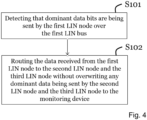
- FIG. 4 showing a flowchart illustrating a method of the monitoring device 200 of monitoring the plurality of LIN buses 105, 115, 125 according to an embodiment.
- the monitoring device 200 monitors, for each of the LIN nodes 100, 110, 120, any event occurring on the LIN buses 105, 115, 125. That is, any data sent via the LIN bus of each LIN node is monitored by the monitoring device 200.
- the first LIN node 100 sends data over the first LIN bus 105 to the first LIN transceiver 201 of the monitoring device 200.
- the monitoring device 200 receives the LIN data via the first LIN transceiver 201, performs a detection process in step S101 (to be described in detail below) and routes in step S102 the LIN data via signal RXD' over path 204 to the signal router 202 and further on via a) signal TXD' over path 213 to the second LIN transceiver 211 over the second LIN bus 115 to the second LIN node 110, and b) signal TXD' over path 223 to the third LIN transceiver 221 over the third LIN bus 125 to the third LIN node 120.
- the LIN nodes 100, 110, 120 are analysed in a non-intrusive manner.
- the LIN nodes 100, 110, 120 are no longer electrically directly connected to each other on a physical layer, but remains connected on a datalink layer.
- the monitoring device 200 may be implemented from scratch in the manner illustrated in Figure 3 , while for an existing vehicle implementing the prior art LIN bus of Figure 1 , the bus would have to be "broken up" such that the monitoring device 200 can be connected as shown in Figure 3 .
- the monitoring device 200 does not affect the LIN network in a manner such that the behaviour of the LIN nodes changes; the LIN nodes 100, 110, 120 will act as if they are connected to a single LIN bus.
- the event detection device 200 may simultaneously send data, for instance originating from the second LIN node 110, to the first LIN node 100 via TXD' wire 203.
- each LIN bus 105, 115, 125 may be driven dominant by both the LIN nodes (in this example the first LIN node 100) and also by the monitoring device 200 at the same time, since the monitoring device 200 routes data received over any one of the LIN buses to the remaining LIN buses.
- Driving a LIN bus dominant from the LIN node side and from the monitoring device side suggests a potential problem, in that the monitoring device 200 cannot determine why the LIN bus 105 is dominant. That is, whether it is because the first LIN data 100 is transmitting dominant data bits or because the monitoring device 200 itself is transmitting dominant data bits.
- the monitoring device 200 may latch up and never release the dominant state to which it has driven the LIN bus 105.
- the latch up problem would occur as soon as at least two LIN nodes out of LIN nodes 100, 110, 120 transmit dominant data bits, thereby causing a dominant state, at the same time.
- the monitoring device 200 detects if any dominant data bits are being sent by any LIN node, 100, 110,120 over the respective LIN bus 105, 115, 125. In this particular example, the monitoring device 200 detects that dominant data is being sent over the first LIN bus 105 by the first LIN node 100.
- the first LIN node 100 is the one sending the dominant data bits
- these dominant bits are routed in step S102 to the second LIN node 110 and the third LIN node 120, in a manner such that the routed dominant bits do not overwrite any dominant bits transferred by the second LIN node 110 and the third LIN node 120 over the LIN buses 115, 125.
- any dominant data received by the monitoring device 200 over any LIN bus 105, 115, 125 is routed to the LIN nodes 100, 110, 120 connected to the remaining LIN buses 105, 115, 125.
- dominant data received from the first LIN node 100 over the first LIN bus 105 is routed to the second LIN node 110 over the second LIN bus 115 and to the third LIN node 120 over the third LIN bus 125.
- any dominant data simultaneously received by the monitoring device 200 for instance from the second LIN node 110 over the second LIN bus 115 is routed to the first LIN node 100 over the first LIN bus 105 and to the third LIN node 120 over the third LIN bus 125, in a manner such that the dominant data received from the first LIN node 100 to not overwrite the dominant data received from the second LIN node 110, and vice versa.
- the dominant data bit detection is performed as will be described in the following.
- the voltage diagram on the left-hand side is identical to that previously illustrated on the right-hand side in Figure 2 .
- the LIN nodes 100, 110, 120 are all configured to output data where a voltage V BUS between the LIN bus 14 and ground potential is in a range from 0 to A% of V SUP , where A is a value lower than 40% of V SUP .
- the voltage diagram on the right-hand side illustrates voltage levels which the monitoring device 200 is configured to comply with according to an embodiment.
- the monitoring device 200 is configured to output dominant data bits to the LIN nodes at a voltage level not exceeding a maximum receive voltage level stipulated by the LIN standard for dominant data bits, i.e. not exceeding 40% of V SUP , but not overlapping with the voltage level with which the LIN nodes are configured to output dominant data bits, i.e. at least B% of V SUP. . That is, the dominant data bits are outputted by the monitoring device 200 at a voltage level falling into range 244, where the range 244 does not overlap with the range 248. However, the range 244 is configured to overlap with range 242, such that the LIN nodes will perceive a voltage in range 244 as dominant data being sent by the monitoring device 200.
- the monitoring device 200 is configured to receive dominant data at a voltage level at least being in the range 248 with which the LIN nodes 100, 110, 120 are configured to output dominant data, i.e. in the range from 0 to A% of V SUP , even though dominant receive range of the monitoring device 200 may be configured to be in range 245, i.e. from 0 to just below B% of V SUP .
- the dominant transmit range 244 should not overlap with the dominant receive range 245, since that would cause a latch-up on the LIN bus.
- range 246 should at least overlap with range 251, but preferably also with range 252 (but not with range 248), even though the range 246 could extend over the voltage span illustrated in Figure 5 . Further, the monitoring device 200 should interpret its own dominant transmit data voltage range 244 as recessive receive, implying that range 246 overlaps with range 244.
- the boundary range between ranges 245 and 246 is denoted 247.
- the monitoring device 200 will advantageously detect a dominate state driven by any of the LIN nodes 100, 110, 120 in case the voltage on the buses 105, 115, 125 is from 0 to A% of V SUP , since range 248 overlaps with range 245, while the monitoring device 200 uses a voltage in the range 244 (which does not overlap with the range 248) to transmit dominant bits, i.e. to cause a dominant state on the LIN bus 14. That is, the LIN nodes 100, 110, 120 output dominant data at a voltage level between 0 and A % of V SUP while the monitoring device 200 outputs dominant data at a voltage level between B and 40% of V SUP , where B should exceed A.
- the receiver dominant detection voltage range of the monitoring device 200 (defined by voltage interval 245) is configured not to overlap its transmitter dominant voltage interval 244. Further, the V BUS voltage where transition recessive-to-dominant and transition dominant-to-recessive occur and is provided by transceiver 201, 211, 221 output signals RXD, lies between voltage intervals 245 and 246 (i.e. the boundary range 247).
- Figure 6 showing a flowchart illustrating a method of the monitoring device 200 of monitoring the plurality of LIN buses 105, 115, 125 according to the embodiment discussed with reference to Figure 5 .
- the monitoring device 200 detects that the voltage of the data sent over the first LIN bus 105 from the first LIN node 100 is in the range from 0 to A% of V SUP in step S101, the correspondingly dominant data received from the first LIN node 100 is routed to the second LIN node 110 and the third LIN node 120 over the second and third LIN bus 115, 125 at a voltage level between B% and 40% of V SUP , where B > A in step S102a.
- this avoids overwriting any dominant data simultaneously being written to the second LIN bus 115 by the second LIN node 110 and/or to the third LIN bus 125 by the third LIN node 120, since the outputted LIN node dominant data always is at a lower voltage level than the outputted monitoring device dominant data, i.e. there is no overlap between ranges 244 and 248.
- the LIN transceiver for a LIN master and LIN slave is internally arranged with a pull-up resistor which will passively pull-up the bus voltage V SUP to be well above 60%, when all LIN nodes are driving at a recessive state.
- a LIN node driving dominant state will actively by means of e.g. a transistor actively drive the voltage to a lower voltage level.
- the LIN node that have the capability to actively drive, or pull down, the bus voltage to the lowest voltage V SUP will be the LIN node determining the resulting bus voltage V SUP .
- the monitoring device 200 is not sending dominant data over the first LIN bus 105, thereby indicating that dominant data is not being sent by the second LIN node 110 and/or by the third LIN node 120 - recessive data is received from the first LIN node 100, which is routed in step S102b from the first LIN node to the second LIN node and the third LIN node at a voltage level between 60% and 100% of V SUP .
- any one of the other LIN nodes 110, 120 would transmit dominant data, that particular dominant data would be routed to the first LIN node 100 and the third LIN node 120, and any recessive data from the first LIN node 100 would thus be overwritten.
- Figure 7 illustrates a further embodiment, where the signal router 202 of the monitoring device 200 encodes data received from the respective LIN node.
- data received from the first LIN node 100 via the first LIN transceiver 201 with signal RXD' over path 204 is combined in a first encoder 216 with data received from the third LIN node via the third LIN transceiver 221 with signal RXD' over path 224.
- the output of the first encoder is 0.
- the signal router 202 will output dominant data, i.e.
- the second LIN transceiver 211 converts to a voltage in the range from B% to 40% of V SUP and outputs to the second LIN node 110 as soon as any one or both of the first LIN node 100 and the third LIN node 120 outputs dominant bits (i.e. a 0 represented by a voltage in the range B% to 40% of V SUP ).
- a second encoder 206 receives data from the second LIN node 110 and the third LIN node 120 and outputs a 0 to the first LIN node 100 if any one or both of the second LIN node 110 and the third LIN node 120 transmits a 0, i.e. a dominant bit, while a third encoder 226 receives data from the first LIN node 100 and the second LIN node 110 and outputs a 0 to the third LIN node 120 if any one or both of the first LIN node 100 and the second LIN node 110 transmits a 0.
- the encoders will output a dominant bit in the form of a 0, which the associated LIN transceivers transmits to the remaining LIN nodes in the form of a voltage in the range from B% to 40% of V SUP .
- the monitoring device 200 monitors any data transmitted by the LIN nodes 100, 110, 120 via the respective signal RXD' over paths 204, 214, 224.
- the signal router 202 comprises a fourth encoder 205, where data received from the first LIN node 100 via the first LIN transceiver 201 with the signal RXD' over path 204 is combined with data received from the second LIN node 110 via the second LIN transceiver 211 with the signal RXD' over path 214 and with data received from the third LIN node 120 via the third LIN transceiver 221 with the signal RXD' over path 224.
- the fourth encoder will output a dominant bit in the form of a 0 over wire 210a.
- the signal RXD" sent over path 210a is routed to a LIN protocol handling device 230, as will be discussed in the following.
- Figure 8a illustrates the LIN protocol handling device 230 according to an embodiment, which functionally comprises a LIN protocol controller 231, or frame processor, which LIN protocol handling device 230 utilizes the signal RXD" carried over path 210a.
- Figure 8b shows the LIN protocol handling device 230 utilizing an alternative signal RXD′′′ carried over path 210b according to an embodiment.
- Path 210b serves the same purpose as the signal path 210a; to provide a combined signal where data being carried over the LIN buses 105, 115, 125 is routed to the LIN protocol handling device 230. Since the monitoring device 200 routes data from the second LIN bus 115 and the third LIN bus 125 to the first LIN bus 105, the data on the first LIN bus 105 (or that on any bus) represent combined data from the first, second and third LIN nodes 100, 110, 120.
- a transceiver 215 is connected to LIN bus 105 and the RXD wire 210b. The transceiver 215 has the same voltage ranges for reception as the LIN Nodes 100,110,120, which are according to ISO 17987.
- the transceiver 215 only uses its receiver part while the transmitter part is not used and therefore the transmitter input TXD signal is permanently tied to a recessive state.
- the transceiver 215 is instead a bus line receiver and there is no transmitter or TXD signal provided.
- the signal 210b or alternatively the signal 210a output from the fourth encoder 205 which combines signals from all the LIN nodes 100, 110, 120 is supplied to the LIN protocol controller 231.
- the LIN protocol controller 231 monitors all events from each LIN node as one composite signal 210a (or 210b), which signal 210a (or 210b) represents what each LIN node 100, 110, 120 actually is seeing on the respective LIN bus 105, 115, 125 (corresponding to the data being transferred over the LIN bus 14 of Figure 1 ), in this particular example the data sent by the first LIN node 100 as previously discussed.
- the LIN protocol controller 231 is capable of interpreting the data received with signal 210a or 210b in the context of a LIN frame.
- the LIN protocol controller 231 maps the data received with signal 210a or 210b into a LIN frame (or a plurality of LIN frames).
- the LIN protocol controller 231 has no TXD path back to any of the transceivers 201, 211, 221 or 215, or encoder 205. This is intentional since it must not affect the data that it shall monitor.
- the transceivers 201, 211, 221 does not support being set to standby mode and continuously pass all symbols like frames headers, frame response and wakeup signals and any dominant state not recognized as a valid LIN protocol symbol to LIN protocol controller 231.
- the LIN protocol controller 231 is configured to recognize wakeup signals according to ISO 17987-3.
- any one of LIN nodes 100, 110, 120 can be a LIN master, and the remaining LIN nodes can be LIN slaves.
- the monitoring device 200 advantageously handles the LIN master being connected to any of the LIN buses 105,115,125. If more than one LIN master would be connected, e.g. the first LIN node 100 being a LIN master and the second LIN node 110 also being a LIN master, this unusual system configuration could be identified by the LIN monitoring device 200.
- the LIN protocol controller 231 is in an embodiment capable of encoding the data received over paths 210a or 210b into LIN frame headers and LIN frame responses as specified in the LIN standard. Examples of such LIN frames will be given hereinbelow. These LIN frames may be provided for display to an operator of the monitoring device 200 via path 231a.
- the LIN protocol controller 231 is in an embodiment capable of mapping events indicated by the LIN protocol controller to specific LIN nodes, and providing this information via paths 232a, 232b, 232c such as for instance "LIN frame header received from the first LIN node” via path 232a, "LIN frame response received from the second LIN node” via path 232b, etc. Any LIN frame format may be used.
- TXD signals 103, 113, 123 from the LIN nodes 100, 110, 120.
- Those TXD signals are not available to the monitoring device 200.
- their waveforms are recreated by the transceivers 201, 211, 221 in the monitoring device 200 as signals 204, 214, 224 and are shown for illustrational purposes.
- Figure 9 illustrates LIN frame header transmission performed by the first LIN node 100 and LIN frame response transmitted by the second LIN node 110, and no transmission by the third LIN node 120.
- a LIN frame 301 consists of a so called frame header and a frame response.
- a BREAK field is used to activate all LIN slaves (i.e. the second LIN node 110 and the third LIN node 120) to listen to the following parts of the header transmitted by a LIN master (i.e. the first LIN node 100 in this case).
- the BREAK field acts as a start-of-frame indicator.
- the header further includes a SYNC field used by the slave nodes for clock synchronization.
- the IDENTIFER defines a specific message address. Thereafter, the frame response part of the LIN frame commences, which is sent by any one of the slave nodes or the master node, the message response consisting of N bytes of DATA and a CHECKSUM field.
- the corresponding LIN node is identified as being the LIN node transmitting the LIN frame header 302, 304, 306 comprising the data transported with signals 210a or 210b. While both the RXD' signal carried over path 214 for the second LIN node 110 and the RXD' signal carried over path 224 for the third LIN node 120 is 1 (i.e. recessive), the RXD' signal carried over path 204 for the first LIN node 100 is indeed 0. Thus, the first node 100 must be the source of the data received over paths 210a, 210b, in this case a LIN master.
- the first LIN node 100 drives the bus into a dominant state resulting in a V BUS in the range 248 (cf. Figure 5 ).
- the monitoring device 200 will thus conclude that it is the first LIN node 100 that sends the dominant data bit over the first LIN bus 105, and as a result route that dominant bit to the second and the third LIN node 110, 120 via paths 213, 223, respectively, over the second and third LIN bus 115, 125 at a V BUS in the range 244.
- the LIN protocol controller 231 will then encode the data sent by the first LIN node 100 and received over path 210a or 210b into a LIN frame headers until all headers fields BREAK, SYNC and IDENTIFIER are encountered..
- LIN bus combination signal 210a or 210b indicates dominant data being transmitted over the LIN buses, and the LIN protocol controller 231 detects from paths 214, 224 only the second node 110 transmitting dominant data thereby successfully completing the LIN frame transmission, indicated with 305.
- the second LIN node 110 drive the bus into a dominant state resulting in a V BUS in the range 248.
- the monitoring device 200 will route a dominant bit to the first LIN node 100 via path 203 over the first LIN bus 105 at a V BUS in the range 244.
- Figure 10 illustrates frame transmission similar to Figure 9 , but in this case it is the first LIN node 100 that transmits both LIN frame header and LIN frame response.
- the first LIN node 100 is a LIN master, as the frame header is transmitted by the first LIN node 100.
- the identification as regards which LIN node is transmitting the frame header is the same is that of Figure 9 .
- the first LIN node 100 drives the bus into a dominant state resulting in a V BUS in the range 248 (cf. Figure 5 ).
- the monitoring device 200 will thus conclude that it is the first LIN node 100 that sends the dominant data bit over the first LIN bus 105, and as a result route that dominant bit to the second and the third LIN node 110, 120 via paths 213, 223, respectively, over the second and third LIN bus 115, 125 at a V BUS in the range 244.
- the LIN protocol controller 231 will then encode the data sent by the first LIN node 100 and received over path 210a or 210b into a LIN frame header until all headers fields BREAK, SYNC and IDENTIFIER are encountered.
- LIN bus combination signal 210a or 210b indicates dominant data being transmitted over the LIN buses, and the LIN protocol controller 231 detects from paths 214, 224 only the second node 110 transmitting dominant data thereby successfully completing the LIN frame transmission, indicated with 313.
- the first LIN node 100 drive the bus into a dominant state resulting in a V BUS in the range 248.
- the monitoring device 200 will route a dominant bit to the second LIN node 110 via path 213 over the second LIN bus 115 at a V BUS in the range 244.
- Figure 11 illustrates a slightly more complex scenario in the form of a LIN frame header transmission performed by the first LIN node 100 and frame response transmitted by the first LIN 100 and the second LIN node 110, resulting in an invalid frame response.
- a frame response is expected to be transmitted by only one LIN node. Again, up until the frame header of the LIN frame is encountered, the behaviour is the same as that described with reference to Figures 9 and 10 .
- the first LIN node 100 is identified as being the LIN node transmission the LIN frame header.
- both the first LIN node 100 and the second LIN node 110 start to transmit a frame response.
- the byte fields of the frame responses are exactly aligned in time so they are transmitted synchronously.
- the byte fields of the first LIN node 100 and second LIN node 110 could be transmitted with slightly different delays relative to each other which would result in invalid byte fields DATA1 trough CHECKSUM.
- any LIN node and also the LIN protocol controller 231 receiving this LIN frame will interpret the CHECKSUM as being incorrect for the DATA 1 trough DATA N fields.
- the LIN protocol handling device will receive the DATA 1 trough CHECKSUM fields from the combined RXD signal 201a or 210b.
- the frame response byte fields DATA 1 trough CHECKSUM will appear as valid byte fields if judged only by the V BUS bus voltages, and not considering the validity of the CHECKSUM, on all buses 105,115,125.
- Figure 12 shows a monitoring device 200 according to an embodiment comprising the signal router 202 and the LIN protocol controller 231 previously discussed.
- the monitoring device 200 further comprises a memory 240 where all or a selected part of measurements being performed can be stored and analysed. For instance, statistics may be provided to an operator. Further, individual signals e.g. carried over paths 204, 214, 224, 210a, or 210b, may be stored for analysis by an operator or a computer.
- the monitoring device 200 may be provided with a display 300 where any signal or detected events in the monitoring device 200 may be displayed.
- the LIN frames over path 231a and events over path(s) 232 are provided for display to an operator of the monitoring device 200.
- the monitoring device 200 comprises one or more processing units 250 in which the functionality of the monitoring device 200 may be implemented. Typically, all functionality of the monitoring device 200 (except for the display 300) may be carried out by such processing unit(s) 250, such as that of the transceivers 201, 211, 221, the signal router 202, the LIN protocol controller 231, etc.
- the steps of the method of the monitoring device 200 for monitoring a plurality of LIN buses may thus in practice be performed by the processing unit 250 embodied in the form of one or more microprocessors arranged to execute a computer program 260 downloaded to a suitable storage medium 270 associated with the microprocessor, such as a Random Access Memory (RAM), a Flash memory or a hard disk drive.
- the processing unit 250 is arranged to cause the monitoring device 200 to carry out the method according to embodiments when the appropriate computer program 260 comprising computer-executable instructions is downloaded to the storage medium 270, being e.g. a non-transitory storage medium, and executed by the processing unit 250.
- the storage medium 252 may also be a computer program product comprising the computer program 260.
- the computer program 260 may be transferred to the storage medium 270 by means of a suitable computer program product, such as a Digital Versatile Disc (DVD) or a memory stick.
- a suitable computer program product such as a Digital Versatile Disc (DVD) or a memory stick.
- the computer program 260 may be downloaded to the storage medium 270 over a network.
- the processing unit 250 may alternatively be embodied in the form of a digital signal processor (DSP), an application specific integrated circuit (ASIC), a field-programmable gate array (FPGA), a complex programmable logic device (CPLD), etc.
- the LIN transceivers of 201, 211, 221 are Integrated Circuit (IC) packaged devices with a transmitter (bus driver) and a receiver (bus line receiver) in the same IC package.
- the transceivers may be constructed by a plurality of passive components and by linear or digital semiconductor components.
- the LIN transceivers of 201, 211,221 can have at least two configurations of the bus driver output voltage and bus comparator input thresholds, where one selected configurations of a plurality of configuration is in operation.
- one configuration can be according to Figure 2
- another configuration can be according to right side of Figure 5 .
- a configuration selection input in one example in the form of digital selection input pin, in another example there is a serial peripheral interface (SPI) bus.
- SPI serial peripheral interface
- At least two LIN buses of 105, 115, 125, and at least two transceivers of 201, 211, 221, and the signal router 202 is part of a LIN bus repeater or LIN bus extender.
- two of LIN buses 105, 115, 125 and two of transceivers 201, 211, 221 are used with a simplified signal router 202.
- the signal router does not need to have encoder 206, 216, 226.
- Encoder 205 is an encoder with two inputs, one being RXD' output 204 of a first transceiver and one being RXD' output 214 of a second transceiver.
- the signal routing is simplified compared to Figure 7 ;
- RXD' output 204 of a first transceiver is directly connected to a TXD' input 213 of a second transceiver, and connected directly to a LIN protocol handling device 230.
- RXD' output 214 of a second transceiver is directly connected to a TXD' 203 of a first transceiver, and connected directly to a LIN protocol handling device 230.
- At least LIN buses 105, 115, 125, and at least transceivers of 201, 211, 221, and the signal router 202 are part of a LIN active star coupler.
- monitoring device 200 is part of a digital storage oscilloscope with serial bus protocol decoding.
- Example of other embodiments are other one-wire or single ended bus systems than LIN, where at least two bus states exist and using transceivers with other transmitted bus voltage levels and receiving thresholds, and other data link layer protocols and other protocol specific events.
Priority Applications (3)
| Application Number | Priority Date | Filing Date | Title |
|---|---|---|---|
| EP19158878.9A EP3700138B1 (en) | 2019-02-22 | 2019-02-22 | Monitoring lin nodes |
| US16/792,550 US11283646B2 (en) | 2019-02-22 | 2020-02-17 | Monitoring local interconnect network (LIN) nodes |
| CN202010101109.XA CN111614531B (zh) | 2019-02-22 | 2020-02-19 | 用于监视lin节点的方法、介质、监视设备 |
Applications Claiming Priority (1)
| Application Number | Priority Date | Filing Date | Title |
|---|---|---|---|
| EP19158878.9A EP3700138B1 (en) | 2019-02-22 | 2019-02-22 | Monitoring lin nodes |
Publications (2)
| Publication Number | Publication Date |
|---|---|
| EP3700138A1 EP3700138A1 (en) | 2020-08-26 |
| EP3700138B1 true EP3700138B1 (en) | 2023-08-02 |
Family
ID=65598436
Family Applications (1)
| Application Number | Title | Priority Date | Filing Date |
|---|---|---|---|
| EP19158878.9A Active EP3700138B1 (en) | 2019-02-22 | 2019-02-22 | Monitoring lin nodes |
Country Status (3)
| Country | Link |
|---|---|
| US (1) | US11283646B2 (zh) |
| EP (1) | EP3700138B1 (zh) |
| CN (1) | CN111614531B (zh) |
Families Citing this family (3)
| Publication number | Priority date | Publication date | Assignee | Title |
|---|---|---|---|---|
| US11277297B2 (en) * | 2019-10-08 | 2022-03-15 | Honeywell International Inc. | Method and apparatus for multiple physical layer interfaces within a single connector |
| US20230318788A1 (en) * | 2022-04-01 | 2023-10-05 | AyDeeKay LLC dba Indie Semiconductor | Single-Thread Detection of Valid Synchronization Headers |
| CN115378911B (zh) * | 2022-10-24 | 2023-01-03 | 上海泰矽微电子有限公司 | 一种lin总线自动寻址系统及实现方法 |
Family Cites Families (11)
| Publication number | Priority date | Publication date | Assignee | Title |
|---|---|---|---|---|
| EP2064823A2 (en) * | 2006-09-06 | 2009-06-03 | Nxp B.V. | Cluster coupler unit and method for synchronizing a plurality of clusters in a time-triggered network |
| CN101690019B (zh) * | 2007-07-06 | 2014-01-08 | 默勒有限公司 | 通过开放式现场总线控制总线联网的设备的系统和方法 |
| EP2339790A1 (en) * | 2009-12-28 | 2011-06-29 | Nxp B.V. | Definition of wakeup bus messages for partial networking |
| DE102011007766A1 (de) | 2011-04-20 | 2012-10-25 | Robert Bosch Gmbh | Verfahren und Vorrichtung zur seriellen Datenübertragung mit umschaltbarer Datencodierung |
| US9276765B2 (en) * | 2011-10-13 | 2016-03-01 | Texas Instruments Incorporated | Apparatus and system for an active star/stub/ring controller area network physical layer transceiver |
| US9778677B2 (en) * | 2012-12-05 | 2017-10-03 | Infineon Technologies Ag | Bit-timing symmetrization |
| DE102012224024A1 (de) | 2012-12-20 | 2014-06-26 | Robert Bosch Gmbh | Datenübertragung unter Nutzung eines Protokollausnahmezustands |
| JP5811141B2 (ja) * | 2013-05-30 | 2015-11-11 | 株式会社デンソー | 通信システム |
| JP6126980B2 (ja) | 2013-12-12 | 2017-05-10 | 日立オートモティブシステムズ株式会社 | ネットワーク装置およびネットワークシステム |
| JP6594732B2 (ja) | 2015-01-20 | 2019-10-23 | パナソニック インテレクチュアル プロパティ コーポレーション オブ アメリカ | 不正フレーム対処方法、不正検知電子制御ユニット及び車載ネットワークシステム |
| EP3258652B1 (en) * | 2016-06-14 | 2019-11-27 | Melexis Technologies NV | Local interconnect network bus architecture |
-
2019
- 2019-02-22 EP EP19158878.9A patent/EP3700138B1/en active Active
-
2020
- 2020-02-17 US US16/792,550 patent/US11283646B2/en active Active
- 2020-02-19 CN CN202010101109.XA patent/CN111614531B/zh active Active
Also Published As
| Publication number | Publication date |
|---|---|
| EP3700138A1 (en) | 2020-08-26 |
| US20200274734A1 (en) | 2020-08-27 |
| CN111614531A (zh) | 2020-09-01 |
| CN111614531B (zh) | 2022-03-01 |
| US11283646B2 (en) | 2022-03-22 |
Similar Documents
| Publication | Publication Date | Title |
|---|---|---|
| EP3700137B1 (en) | Monitoring can nodes | |
| US8213321B2 (en) | Controller area network condition monitoring and bus health on in-vehicle communications networks | |
| US11283646B2 (en) | Monitoring local interconnect network (LIN) nodes | |
| CN105700510B (zh) | Can通信系统的错误分散检测方法及can通信系统 | |
| EP3809638A1 (en) | Detecting manipulation of data on a can bus | |
| US20220239576A1 (en) | Error detection test device for a subscriber station of a serial bus system and method for testing mechanisms for detecting errors in a communication in a serial bus system | |
| US11463198B2 (en) | Security module for a serial communications device | |
| CN107959599A (zh) | 一种Bus_Off故障测试系统及测试方法 | |
| US9678919B2 (en) | Collision detection in EIA-485 bus systems | |
| CN107097646B (zh) | 对报警显示进行处理的方法 | |
| CN106324420B (zh) | 一种显示故障检测方法 | |
| CN112249088B (zh) | 双显示系统互诊断与数据同步的方法、双显示系统和列车 | |
| CN207652457U (zh) | 一种Bus_Off故障测试系统 | |
| US11671280B2 (en) | Network node with diagnostic signalling mode | |
| US11036664B2 (en) | Method for determining the transmission speed of a communication module in adapting a connected communication module to a bus and a device for said method | |
| JP6633157B1 (ja) | 検査システム | |
| US10515039B2 (en) | Vehicle USB hub system | |
| Novak et al. | Automated testing of electronic control units compatibility in vehicle CAN networks | |
| CN110557298A (zh) | 用于测试系统的方法和系统 | |
| US20230231739A1 (en) | Inspection apparatus and inspection method | |
| Laufenberg et al. | CAN Simulation Framework-From Classic CAN to CAN XL | |
| CN117406693A (zh) | 车载系统的故障检测方法和装置、存储介质及电子设备 | |
| CN115167340A (zh) | 车载控制器的总线故障响应测试系统及方法 | |
| Anusha et al. | Development of automatic test script generation (ATSG) tool for active safety software validation | |
| CN117271246A (zh) | 一种i2c设备调试方法 |
Legal Events
| Date | Code | Title | Description |
|---|---|---|---|
| PUAI | Public reference made under article 153(3) epc to a published international application that has entered the european phase |
Free format text: ORIGINAL CODE: 0009012 |
|
| STAA | Information on the status of an ep patent application or granted ep patent |
Free format text: STATUS: THE APPLICATION HAS BEEN PUBLISHED |
|
| AK | Designated contracting states |
Kind code of ref document: A1 Designated state(s): AL AT BE BG CH CY CZ DE DK EE ES FI FR GB GR HR HU IE IS IT LI LT LU LV MC MK MT NL NO PL PT RO RS SE SI SK SM TR |
|
| AX | Request for extension of the european patent |
Extension state: BA ME |
|
| STAA | Information on the status of an ep patent application or granted ep patent |
Free format text: STATUS: REQUEST FOR EXAMINATION WAS MADE |
|
| 17P | Request for examination filed |
Effective date: 20210226 |
|
| RBV | Designated contracting states (corrected) |
Designated state(s): AL AT BE BG CH CY CZ DE DK EE ES FI FR GB GR HR HU IE IS IT LI LT LU LV MC MK MT NL NO PL PT RO RS SE SI SK SM TR |
|
| STAA | Information on the status of an ep patent application or granted ep patent |
Free format text: STATUS: EXAMINATION IS IN PROGRESS |
|
| 17Q | First examination report despatched |
Effective date: 20210615 |
|
| REG | Reference to a national code |
Ref country code: DE Ref legal event code: R079 Ref document number: 602019033847 Country of ref document: DE Free format text: PREVIOUS MAIN CLASS: H04L0012260000 Ipc: H04L0012403000 Ref country code: DE Ref legal event code: R079 Free format text: PREVIOUS MAIN CLASS: H04L0012260000 |
|
| GRAP | Despatch of communication of intention to grant a patent |
Free format text: ORIGINAL CODE: EPIDOSNIGR1 |
|
| STAA | Information on the status of an ep patent application or granted ep patent |
Free format text: STATUS: GRANT OF PATENT IS INTENDED |
|
| RIC1 | Information provided on ipc code assigned before grant |
Ipc: H04L 12/46 20060101ALI20230403BHEP Ipc: H04L 12/403 20060101AFI20230403BHEP |
|
| INTG | Intention to grant announced |
Effective date: 20230420 |
|
| RIN1 | Information on inventor provided before grant (corrected) |
Inventor name: ANTONSSON, ANDERS |
|
| GRAS | Grant fee paid |
Free format text: ORIGINAL CODE: EPIDOSNIGR3 |
|
| GRAA | (expected) grant |
Free format text: ORIGINAL CODE: 0009210 |
|
| STAA | Information on the status of an ep patent application or granted ep patent |
Free format text: STATUS: THE PATENT HAS BEEN GRANTED |
|
| AK | Designated contracting states |
Kind code of ref document: B1 Designated state(s): AL AT BE BG CH CY CZ DE DK EE ES FI FR GB GR HR HU IE IS IT LI LT LU LV MC MK MT NL NO PL PT RO RS SE SI SK SM TR |
|
| REG | Reference to a national code |
Ref country code: GB Ref legal event code: FG4D |
|
| REG | Reference to a national code |
Ref country code: CH Ref legal event code: EP |
|
| P01 | Opt-out of the competence of the unified patent court (upc) registered |
Effective date: 20230710 |
|
| REG | Reference to a national code |
Ref country code: DE Ref legal event code: R096 Ref document number: 602019033847 Country of ref document: DE |
|
| REG | Reference to a national code |
Ref country code: IE Ref legal event code: FG4D |
|
| REG | Reference to a national code |
Ref country code: LT Ref legal event code: MG9D |
|
| REG | Reference to a national code |
Ref country code: NL Ref legal event code: MP Effective date: 20230802 |
|
| REG | Reference to a national code |
Ref country code: AT Ref legal event code: MK05 Ref document number: 1596090 Country of ref document: AT Kind code of ref document: T Effective date: 20230802 |
|
| PG25 | Lapsed in a contracting state [announced via postgrant information from national office to epo] |
Ref country code: GR Free format text: LAPSE BECAUSE OF FAILURE TO SUBMIT A TRANSLATION OF THE DESCRIPTION OR TO PAY THE FEE WITHIN THE PRESCRIBED TIME-LIMIT Effective date: 20231103 |
|
| PG25 | Lapsed in a contracting state [announced via postgrant information from national office to epo] |
Ref country code: IS Free format text: LAPSE BECAUSE OF FAILURE TO SUBMIT A TRANSLATION OF THE DESCRIPTION OR TO PAY THE FEE WITHIN THE PRESCRIBED TIME-LIMIT Effective date: 20231202 |
|
| PG25 | Lapsed in a contracting state [announced via postgrant information from national office to epo] |
Ref country code: SE Free format text: LAPSE BECAUSE OF FAILURE TO SUBMIT A TRANSLATION OF THE DESCRIPTION OR TO PAY THE FEE WITHIN THE PRESCRIBED TIME-LIMIT Effective date: 20230802 Ref country code: RS Free format text: LAPSE BECAUSE OF FAILURE TO SUBMIT A TRANSLATION OF THE DESCRIPTION OR TO PAY THE FEE WITHIN THE PRESCRIBED TIME-LIMIT Effective date: 20230802 Ref country code: PT Free format text: LAPSE BECAUSE OF FAILURE TO SUBMIT A TRANSLATION OF THE DESCRIPTION OR TO PAY THE FEE WITHIN THE PRESCRIBED TIME-LIMIT Effective date: 20231204 Ref country code: NO Free format text: LAPSE BECAUSE OF FAILURE TO SUBMIT A TRANSLATION OF THE DESCRIPTION OR TO PAY THE FEE WITHIN THE PRESCRIBED TIME-LIMIT Effective date: 20231102 Ref country code: NL Free format text: LAPSE BECAUSE OF FAILURE TO SUBMIT A TRANSLATION OF THE DESCRIPTION OR TO PAY THE FEE WITHIN THE PRESCRIBED TIME-LIMIT Effective date: 20230802 Ref country code: LV Free format text: LAPSE BECAUSE OF FAILURE TO SUBMIT A TRANSLATION OF THE DESCRIPTION OR TO PAY THE FEE WITHIN THE PRESCRIBED TIME-LIMIT Effective date: 20230802 Ref country code: LT Free format text: LAPSE BECAUSE OF FAILURE TO SUBMIT A TRANSLATION OF THE DESCRIPTION OR TO PAY THE FEE WITHIN THE PRESCRIBED TIME-LIMIT Effective date: 20230802 Ref country code: IS Free format text: LAPSE BECAUSE OF FAILURE TO SUBMIT A TRANSLATION OF THE DESCRIPTION OR TO PAY THE FEE WITHIN THE PRESCRIBED TIME-LIMIT Effective date: 20231202 Ref country code: HR Free format text: LAPSE BECAUSE OF FAILURE TO SUBMIT A TRANSLATION OF THE DESCRIPTION OR TO PAY THE FEE WITHIN THE PRESCRIBED TIME-LIMIT Effective date: 20230802 Ref country code: GR Free format text: LAPSE BECAUSE OF FAILURE TO SUBMIT A TRANSLATION OF THE DESCRIPTION OR TO PAY THE FEE WITHIN THE PRESCRIBED TIME-LIMIT Effective date: 20231103 Ref country code: FI Free format text: LAPSE BECAUSE OF FAILURE TO SUBMIT A TRANSLATION OF THE DESCRIPTION OR TO PAY THE FEE WITHIN THE PRESCRIBED TIME-LIMIT Effective date: 20230802 Ref country code: AT Free format text: LAPSE BECAUSE OF FAILURE TO SUBMIT A TRANSLATION OF THE DESCRIPTION OR TO PAY THE FEE WITHIN THE PRESCRIBED TIME-LIMIT Effective date: 20230802 |
|
| PG25 | Lapsed in a contracting state [announced via postgrant information from national office to epo] |
Ref country code: PL Free format text: LAPSE BECAUSE OF FAILURE TO SUBMIT A TRANSLATION OF THE DESCRIPTION OR TO PAY THE FEE WITHIN THE PRESCRIBED TIME-LIMIT Effective date: 20230802 |
|
| PG25 | Lapsed in a contracting state [announced via postgrant information from national office to epo] |
Ref country code: ES Free format text: LAPSE BECAUSE OF FAILURE TO SUBMIT A TRANSLATION OF THE DESCRIPTION OR TO PAY THE FEE WITHIN THE PRESCRIBED TIME-LIMIT Effective date: 20230802 |
|
| PG25 | Lapsed in a contracting state [announced via postgrant information from national office to epo] |
Ref country code: SM Free format text: LAPSE BECAUSE OF FAILURE TO SUBMIT A TRANSLATION OF THE DESCRIPTION OR TO PAY THE FEE WITHIN THE PRESCRIBED TIME-LIMIT Effective date: 20230802 Ref country code: RO Free format text: LAPSE BECAUSE OF FAILURE TO SUBMIT A TRANSLATION OF THE DESCRIPTION OR TO PAY THE FEE WITHIN THE PRESCRIBED TIME-LIMIT Effective date: 20230802 Ref country code: ES Free format text: LAPSE BECAUSE OF FAILURE TO SUBMIT A TRANSLATION OF THE DESCRIPTION OR TO PAY THE FEE WITHIN THE PRESCRIBED TIME-LIMIT Effective date: 20230802 Ref country code: EE Free format text: LAPSE BECAUSE OF FAILURE TO SUBMIT A TRANSLATION OF THE DESCRIPTION OR TO PAY THE FEE WITHIN THE PRESCRIBED TIME-LIMIT Effective date: 20230802 Ref country code: DK Free format text: LAPSE BECAUSE OF FAILURE TO SUBMIT A TRANSLATION OF THE DESCRIPTION OR TO PAY THE FEE WITHIN THE PRESCRIBED TIME-LIMIT Effective date: 20230802 Ref country code: CZ Free format text: LAPSE BECAUSE OF FAILURE TO SUBMIT A TRANSLATION OF THE DESCRIPTION OR TO PAY THE FEE WITHIN THE PRESCRIBED TIME-LIMIT Effective date: 20230802 Ref country code: SK Free format text: LAPSE BECAUSE OF FAILURE TO SUBMIT A TRANSLATION OF THE DESCRIPTION OR TO PAY THE FEE WITHIN THE PRESCRIBED TIME-LIMIT Effective date: 20230802 |
|
| PGFP | Annual fee paid to national office [announced via postgrant information from national office to epo] |
Ref country code: DE Payment date: 20240123 Year of fee payment: 6 Ref country code: GB Payment date: 20240123 Year of fee payment: 6 |