EP3699542B1 - Véhicule furtif avec système d'arme integré à déploiement rapide - Google Patents
Véhicule furtif avec système d'arme integré à déploiement rapide Download PDFInfo
- Publication number
- EP3699542B1 EP3699542B1 EP19158468.9A EP19158468A EP3699542B1 EP 3699542 B1 EP3699542 B1 EP 3699542B1 EP 19158468 A EP19158468 A EP 19158468A EP 3699542 B1 EP3699542 B1 EP 3699542B1
- Authority
- EP
- European Patent Office
- Prior art keywords
- vehicle
- weapon system
- weapon
- recess
- roof
- Prior art date
- Legal status (The legal status is an assumption and is not a legal conclusion. Google has not performed a legal analysis and makes no representation as to the accuracy of the status listed.)
- Active
Links
Images



Classifications
-
- F—MECHANICAL ENGINEERING; LIGHTING; HEATING; WEAPONS; BLASTING
- F41—WEAPONS
- F41A—FUNCTIONAL FEATURES OR DETAILS COMMON TO BOTH SMALLARMS AND ORDNANCE, e.g. CANNONS; MOUNTINGS FOR SMALLARMS OR ORDNANCE
- F41A23/00—Gun mountings, e.g. on vehicles; Disposition of guns on vehicles
- F41A23/20—Gun mountings, e.g. on vehicles; Disposition of guns on vehicles for disappearing guns
-
- F—MECHANICAL ENGINEERING; LIGHTING; HEATING; WEAPONS; BLASTING
- F41—WEAPONS
- F41A—FUNCTIONAL FEATURES OR DETAILS COMMON TO BOTH SMALLARMS AND ORDNANCE, e.g. CANNONS; MOUNTINGS FOR SMALLARMS OR ORDNANCE
- F41A23/00—Gun mountings, e.g. on vehicles; Disposition of guns on vehicles
- F41A23/34—Gun mountings, e.g. on vehicles; Disposition of guns on vehicles on wheeled or endless-track vehicles
-
- F—MECHANICAL ENGINEERING; LIGHTING; HEATING; WEAPONS; BLASTING
- F41—WEAPONS
- F41H—ARMOUR; ARMOURED TURRETS; ARMOURED OR ARMED VEHICLES; MEANS OF ATTACK OR DEFENCE, e.g. CAMOUFLAGE, IN GENERAL
- F41H7/00—Armoured or armed vehicles
- F41H7/02—Land vehicles with enclosing armour, e.g. tanks
Definitions
- the present invention emerges from the technological field of the integration of weapon systems of limited space, for example weapon systems of different calibers on a light (armored) vehicle, said calibers covering the range of small and medium calibers.
- the present invention relates more particularly to a vehicle comprising a retractable weapon system, the weapon system being entirely concealed in the roof of the vehicle when it is in the retracted position, and able to deploy rapidly when it is put into operation. surgery.
- the term “stealth vehicle” is understood to mean a military vehicle capable of approaching as close as possible to the enemy without being spotted.
- US 6,009,791 A discloses an armored vehicle comprising a retractable mechanized platform, on which is placed a weapon.
- the weapon is located inside the vehicle when the platform is in a lowered position and is located above the roof of the vehicle when the platform is in a raised position.
- This platform does not offer speed implementation or compactness in its use and is not intended for small arms.
- US 4,667,565 A describes a rapid response and anti-terrorism vehicle comprising a hatch-type opening provided in the roof to deploy an automatic weapon, as well as a structure fixed to the vehicle floor with a pivoting frame.
- a weapon support ring is pivotally attached to the pivoting frame so that the assembly is horizontal and positioned in the roof opening when the frame is pivoted to the firing position.
- the weapon's withdrawal system is bulky and is not intended for small arms.
- the document EP 0411 993 B1 describes a light armored vehicle comprising a deployable light anti-aircraft gun mount on its roof.
- the gun is thus foldable on the roof of the vehicle, but it is not camouflaged.
- the apparent weapon also causes the reduction of aerodynamics as a drawback and obliges the driver to limit the speed of the vehicle. In addition, the shooter must be outside the cockpit to use the weapon.
- the document EP 0 612 969 B1 discloses an all-terrain vehicle having an apparatus mounted on the cargo area and overlooking the driver's cab, in particular for anti-aircraft defense.
- the apparatus is arranged on a platform held on a frame firmly anchored to the cargo area so as to be able to pivot about a pivoting shaft extending transversely to the longitudinal axis of the vehicle, from a position of use. approximately horizontal lying substantially parallel to the cargo area below the roof contour to an approximately vertical transport position extending along the rear wall of the driver's cab, and vice versa. This is again a cumbersome and complex solution.
- the document GB 1 522 042 A discloses an installation for launching a missile from an armored vehicle comprising an enclosure which can be maintained at a pressure greater than the external pressure, comprising a housing, at least one launch pad mounted on a mobile support, means for moving the support between a firing position outside the housing and a retracted position in which the support and the (or each) ramp are inside the housing, the housing being provided with a first opening for the passage of the ramp through, the first opening being able to be closed by a hatch in the retracted position of the support, and means for controlling the orientation of the movable support in azimuth and in elevation, characterized in that the box constitutes an assembly to be installed at the 'interior of the vehicle enclosure with the first opening coplanar with an upper wall of the enclosure and with the mobile support substantially movable vertically and in that it is provided with a second loading opening to communicate with the interior of the enclosure and reclosable by a hatch, the hatches of the first and second openings being airtight so that the
- the Carmor company markets a tactical, buggy-style armored fighting vehicle called "Mantis" TM which has a retractable weapon system on its rear platform, but not camouflaged.
- the object of the present invention is to overcome the drawbacks of the state of the art.
- the present invention aims to provide an armored land vehicle according to claim 1 with a retractable weapon system, the weapon system being entirely concealed in the upper part of the vehicle casing when it is in the retracted position so that the armament is not visible to a person outside the vehicle.
- the objective is that the vehicle can then be confused with a standard vehicle possibly of the civilian type, and keep an optimal aerodynamics allowing it normal or even high travel speeds.
- the present invention aims to provide a compact retractable weapon system, which can be reloaded from inside the vehicle so that no operation forces the crew to exit the vehicle.
- the present invention also aims to allow rapid and easy placement of the weapon system from the storage or rest position to the operational deployed position.
- the automated mechanism used must be able to be operational quickly, typically in less than 5 seconds.
- the present invention also aims to provide a vehicle whose roof is sealed to the external environment when the weapon system is folded into the passenger compartment.
- the present invention also aims to avoid providing a door such as a hatch in the roof of the vehicle for the deployment of a weapon and therefore to maintain the integrity of the protection provided by the vehicle.
- the present invention relates to a generally armored vehicle with a retractable weapon system, the vehicle being designed so that the weapon system is entirely concealed in the upper part of the vehicle casing when it is in the retracted position so that the weapon is not visible to a person outside the vehicle.
- the weapon system 4 comprises at least one weapon with an ammunition caliber of up to 25-30 mm or a grenade launcher (caliber 40 mm).
- the vehicle 1 with the weapon system 4 in the retracted position is shown in the figures. figures 1, 2 , 5 , 7 and 8 . Furthermore, the vehicle with the weapon system 4 in the deployed position is shown in the figures 3, 4 , 6 , 9 and 10 .
- the vehicle 1 comprises a roof 2 and has a recess 3 at the level of the roof 2 as shown in the figures. figures 5 and 6 .
- This recess 3 advantageously comprises a platform or a base making it possible to accommodate the weapon system 4.
- An automatic mechanism 8, such as for example a jack, makes it possible to ensure the displacement of the weapon system 4 between two positions. The first position corresponds to that where the weapon system 4 is retracted and folded into the recess 3 of the roof. The second position corresponds to that where the weapon system 4 is deployed out of the recess 3 of the roof 2 and is ready to fire.
- the automatic mechanism 8 allows rapid and easy positioning of the weapon system 4 in the deployed position so as to be operational typically in less than 5 seconds.
- a possibly armored protective cap 5 covers the recess 3 when the weapon system 4 is in the first position, namely the retracted position.
- the roof 2 is completely closed on the recess 3 comprising the weapon and is therefore no longer visible.
- the recess 3 is adjusted or reported exactly to the dimensions of the weapon system 4, as illustrated by the figures 8 to 10 .
- the surface of the cover 5 is therefore substantially identical to the surface of the recess in the roof 2, said surface of the recess being considered at the external level and in the extension of the roof.
- the weapon system 4 therefore fits perfectly into the recess 3 of the roof, and the cover 5 is adjusted to the dimensions of the weapon so as to have the smallest possible attached surface.
- the cap 5 and the recess 3 therefore have optimized dimensions and geometries, depending on the dimensions of the weapon.
- the armor of the recess 3 is advantageously limited to the crew survival cell and / or to the weapon reloading area.
- the cap 5 is secured to the weapon system 4, as shown in the figures 5 and 6 , so that it moves with the weapon system as it moves from one position to another.
- the generally armored fairing 5 exactly covers the recess 3 when the weapon system 4 is in the first retracted position, ensuring the continuity of the surface of the roof 2 and is raised with the weapon system 4 when the latter is in the second position deployed, providing protection against projectiles that may possibly come from above.
- this armored cap 5 can also take the form of a shell completely surrounding the weapon, as also illustrated by the figures 9 and 10 .
- the weapon system 4 can be articulated using articulated arms or a pantograph (not shown). In this way, when it is deployed, it may end up off-center with respect to the recess 3 provided in the roof, as illustrated on the figure. figure 4 .
- the weapon system 4 comprises an integrated optic 11, for example disposed laterally with respect to the weapon.
- a sealed space 6 is advantageously created between the recess of the roof and the armored cover, to close the roof on the weapon system 4. Still advantageously, seals ensure the tightness of the sealed space 6 when the weapon system (4) is in the first position.
- the vehicle 1 can also include one or two ammunition supply rails ("feeders", not shown) located under the recess 3 of the vehicle in order to be able to feed the weapon system from inside the vehicle 1.
- the weapon system is installed on a weapon support 9, the weapon system 4 being connected via said weapon support 9 to a shaft or bearing 10.
- the weapon support 9 can therefore rotate 360 ° around a vertical axis.
- the vehicle further advantageously comprises an internal hatch 7 made under the roof 2 of the vehicle, at the level of the recess 3 in order to have access to the weapon system from inside the vehicle 1.
- the entire mechanism itself can be integrated into a revolving basket comprising the retractable weapon and its mount, the on-board electronics as well as the feeders.
- the weapon system is entirely concealed in the recess of the roof when it is in the retracted position, so that such a system is unsuspected by a person outside the vehicle.
- the vehicle has the appearance of a standard vehicle, ideally of the civilian type such as a buggy, a 4x4, an SUV, etc. without armament.
- the weapon is protected by the armored cap when it is retracted into the recess in the roof.
- the operating time is considerably reduced, of the order of a few seconds, and preferably, the weapon system is operational in less than 5 seconds.
- automatic stationing is secure, easy and requires only one man.
- the retractable weapon system of the vehicle of the invention is advantageously compact and can be recharged from inside the vehicle.
- the weapon is accessible from inside the vehicle thanks to the internal hatch.
- the present invention aims to provide a vehicle whose roof is sealed to the external environment when the weapon system is folded into the passenger compartment.
- the vehicle maintains its aerodynamics and the weapon system is not annoying when it is not deployed, which allows to drive at normal to high speeds when the weapon is folded in the cockpit.
Landscapes
- Engineering & Computer Science (AREA)
- General Engineering & Computer Science (AREA)
- Aiming, Guidance, Guns With A Light Source, Armor, Camouflage, And Targets (AREA)
- Body Structure For Vehicles (AREA)
- Fittings On The Vehicle Exterior For Carrying Loads, And Devices For Holding Or Mounting Articles (AREA)
Description
- La présente invention ressort du domaine technologique de l'intégration de systèmes d'arme d'encombrement limité, par exemple des systèmes d'arme de différents calibres sur un véhicule (blindé) léger, lesdits calibres couvrant la gamme des petits et moyens calibres.
- La présente invention se rapporte plus particulièrement à un véhicule comprenant un système d'arme escamotable, le système d'arme étant entièrement dissimulé dans le toit du véhicule lorsqu'il est en position rétractée, et apte à se déployer rapidement lors de sa mise en opération.
- Dans le contexte de la présente invention, on entend par véhicule furtif un véhicule militaire capable de s'approcher au plus près de l'ennemi sans être repéré.
- On connaît des systèmes d'armes escamotables agencés sur des véhicules militaires qui ont la propriété d'être des systèmes volumineux et encombrants, qui ne permettent pas une mise en service rapide.
- Le document
US 6,009,791 A divulgue un véhicule blindé comprenant une plateforme rétractable mécanisée, sur laquelle est placée une arme. L'arme est située à l'intérieur du véhicule quand la plateforme est dans une position abaissée et est localisée au-dessus du toit du véhicule quand la plateforme est dans une position surélevée. Cette plateforme n'offre ni rapidité de mise en œuvre ni compacité dans son utilisation et n'est pas destinée aux armes de petits calibres. - Le document
US 4,667,565 A décrit un véhicule d'intervention rapide et antiterroriste comprenant une ouverture de type trappe prévue dans le toit pour déployer une arme automatique, ainsi qu'une structure fixée au plancher du véhicule avec un cadre pivotant. Un anneau de support d'arme est fixé de manière pivotante au cadre pivotant de sorte que l'ensemble soit horizontal et positionné dans l'ouverture du toit lorsque le cadre est pivoté vers la position de tir. Dans ce document, le système de repli de l'arme est encombrant et n'est pas destiné aux armes de petits calibres. - Le document
EP 0411 993 B1 décrit un véhicule blindé léger comprenant un affût déployable de canon anti-aérien léger sur son toit. Le canon est ainsi repliable sur le toit du véhicule, mais il n'est pas camouflé. L'arme apparente engendre également comme inconvénient la diminution de l'aérodynamisme et oblige le conducteur à limiter la vitesse du véhicule. De plus, le tireur doit être en dehors de l'habitacle pour utiliser l'arme. - Le document
EP 0 612 969 B1 divulgue un véhicule tout-terrain ayant un appareil monté sur la zone de cargaison et surplombant la cabine de conduite, en particulier pour la défense anti-aérienne. L'appareil est disposé sur une plateforme maintenue sur un cadre solidement ancré à la zone de cargaison de manière à pouvoir pivoter autour d'un arbre pivotant s'étendant transversalement par rapport à l'axe longitudinal du véhicule, depuis une position d'utilisation approximativement horizontale située sensiblement parallèlement à la zone de chargement en dessous du contour du toit jusqu'à une position de transport approximativement verticale s'étendant le long de la paroi arrière de la cabine du conducteur, et vice versa. Il s'agit à nouveau d'une solution encombrante et complexe. - Le document
GB 1 522 042 A - La société Carmor (Israël) commercialise un véhicule de combat blindé tactique, de style buggy, appelé « Mantis »™ qui dispose sur sa plateforme arrière d'un système d'arme rétractable mais non camouflé.
- A l'heure actuelle il existe de nombreuses applications sur véhicules terrestres plus ou moins lourds de type 4X4, buggy, etc. qui présentent un système d'arme visible et généralement amovible manuellement, par exemple du type système d'arme téléopéré (RWS pour remote weapon system). Ces systèmes permettent d'offrir au tireur une protection dans le véhicule.
- Cependant, ces systèmes d'armes ou tourelleaux, téléopérés ou non, présentent, outre le fait d'être apparents, le désavantage d'offrir une prise au vent ou encore de s'encrasser (sable) et de ne pas pouvoir être rechargés par l'intérieur du véhicule. De plus, ces systèmes contribuent à élever le centre de gravité du véhicule et peuvent éventuellement créer un balourd ou un déséquilibre de l'ensemble.
- La présente invention a pour but de pallier les inconvénients de l'état de la technique.
- La présente invention vise à réaliser un véhicule terrestre blindé selon la revendication 1 avec système d'arme escamotable, le système d'arme étant entièrement dissimulé dans la partie supérieure de l'enveloppe du véhicule lorsqu'il est en position rétractée afin que l'armement ne soit pas visible pour une personne située à l'extérieur du véhicule. L'objectif est que le véhicule puisse alors être confondu avec un véhicule standard éventuellement de type civil, et garder un aérodynamisme optimal lui permettant des vitesses de déplacement normales, voire élevées.
- En outre, la présente invention a pour but de réaliser un système d'arme escamotable compact, qui peut être rechargé par l'intérieur du véhicule de sorte qu'aucune opération n'oblige l'équipage à sortir du véhicule.
- La présente invention vise également à permettre un placement rapide et aisé du système d'arme de la position de stockage ou de repos à la position déployée opérationnelle. Le mécanisme automatisé utilisé doit permettre d'être opérationnel rapidement, typiquement en moins de 5 secondes.
- La présente invention vise encore à réaliser un véhicule dont la toiture est étanche à l'environnement extérieur lorsque le système arme est replié dans l'habitacle.
- La présente invention vise encore à éviter de ménager une porte telle qu'une écoutille dans le toit du véhicule pour le déploiement d'une arme et donc de conserver l'intégrité de la protection assurée par le véhicule.
-
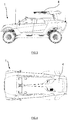
- La
figure 1 représente schématiquement une vue de profil du véhicule avec le système d'arme en position rétractée. - La
figure 2 représente schématiquement une vue du dessus du véhicule avec le système d'arme en position rétractée. - La
figure 3 représente schématiquement une vue de profil du véhicule avec le système d'arme en position déployée opérationnelle. - La
figure 4 représente schématiquement une vue du dessus du véhicule avec le système d'arme en position déployée opérationnelle. - La
figure 5 représente schématiquement une vue en coupe du toit du véhicule avec le système d'arme en position rétractée. - La
figure 6 représente schématiquement une vue en coupe du toit du véhicule avec le système d'arme en position déployée. - Les
figures 7 et 8 représentent schématiquement des vues en trois dimensions du toit du véhicule avec le système d'arme en position rétractée. - Les
figures 9 et 10 représentent schématiquement des vues en trois dimensions du toit du véhicule avec le système d'arme en position déployée opérationnelle. -
- (1) Véhicule
- (2) toit du véhicule
- (3) renfoncement dans le toit du véhicule
- (4) système d'arme
- (5) coiffe blindée
- (6) espace étanche contenant le système d'arme
- (7) trappe interne d'accès au système d'arme
- (8) mécanisme rétractable de déplacement du système d'arme
- (9) support d'arme
- (10) arbre du support d'arme
- (11) optique intégrée
- La présente invention se rapporte à un véhicule terrestre blindé comprenant :
- un toit délimité par une ouverture contenant un renfoncement ;
- un système d'arme escamotable pouvant être déployé automatiquement entre une première position escamotée située à l'intérieur du véhicule dans le renfoncement du toit et une deuxième position déployée et opérationnelle située à l'extérieur du véhicule ;
- un mécanisme automatique apte à assurer, en utilisation, le déplacement du système d'arme entre les deux positions précitées ;
- une coiffe blindée solidaire du système d'armes permettant de recouvrir le renfoncement en effectuant une jonction entre un contour externe de ladite coiffe et une périphérie de l'ouverture du toit selon un emboîtement parfait et dans le prolongement de la surface du toit (2), lorsque le système d'arme se trouve dans la première position escamotée ;
- Selon des modes de réalisation particuliers de l'invention, le véhicule comporte en outre au moins une des caractéristiques suivantes ou une combinaison appropriée de celles-ci :
- la coiffe blindée recouvre entièrement le renfoncement dans la partie supérieure de l'enveloppe du véhicule ;
- la fermeture du renfoncement par la coiffe crée un espace étanche contenant le système d'arme, l'étanchéité est assurée au niveau de l'espace étanche par au moins un joint ;
- la coiffe recouvre uniquement la partie supérieure du système d'arme ou constitue une coque de protection entourant complètement au moins une partie du système d'arme ;
- le mécanisme automatique assurant, en utilisation, le déplacement du système d'arme comprend au moins un vérin ;
- le véhicule comprend également un rail d'alimentation en munitions situé sous le renfoncement du toit du véhicule afin de pouvoir alimenter le système d'arme depuis l'intérieur du véhicule ;
- le système d'arme est installé sur un support d'arme, ledit support d'arme étant monté de manière pivotante avec le système d'arme par l'intermédiaire d'un roulement ;
- le support d'arme est monté pivotant à 360° autour d'un axe vertical ;
- le véhicule comprend également une trappe interne réalisée sous le renfoncement du toit du véhicule, afin de permettre un accès au système d'arme depuis l'intérieur du véhicule ;
- le véhicule blindé est un véhicule militaire furtif, tactique, léger, ayant une apparence externe de type 4x4, SUV ou buggy.
- La présente invention se rapporte à un véhicule généralement blindé avec système d'arme escamotable, le véhicule étant conçu pour que le système d'arme soit entièrement dissimulé dans la partie supérieure de l'enveloppe du véhicule lorsqu'il est en position rétractée de sorte que l'armement ne soit pas visible pour une personne située à l'extérieur du véhicule. En particulier, le système d'arme 4 comprend au moins une arme avec un calibre de munition allant jusqu'à 25-30 mm ou un lance-grenades (calibre 40 mm) .
- Selon une forme d'exécution de l'invention, le véhicule 1 avec le système d'arme 4 en position escamotée est représenté sur les
figures 1, 2 ,5 ,7 et 8 . Par ailleurs, le véhicule avec le système d'arme 4 en position déployée est représenté sur lesfigures 3, 4 ,6 ,9 et 10 . - Le véhicule 1 selon l'invention comprend un toit 2 et présente un renfoncement 3 au niveau du toit 2 tel que représenté sur les
figures 5 et 6 . Ce renfoncement 3 comprend avantageusement une plateforme ou un socle permettant d'accueillir le système d'arme 4. Un mécanisme automatique 8, tel que par exemple un vérin, permet d'assurer le déplacement du système d'arme 4 entre deux positions. La première position correspond à celle où le système d'arme 4 est escamoté et replié dans le renfoncement 3 du toit. La seconde position correspond à celle où le système d'arme 4 est déployé hors du renfoncement 3 du toit 2 et est prêt à tirer. Le mécanisme automatique 8 permet une mise en place rapide et aisée du système d'arme 4 en position déployée de manière à être opérationnel typiquement en moins de 5 secondes. - Tel qu'illustré aux
figures 5 et 6 , une coiffe de protection éventuellement blindée 5 recouvre le renfoncement 3 lorsque le système d'arme 4 est dans la première position, à savoir la position escamotée. De cette manière, le toit 2 est totalement refermé sur le renfoncement 3 comprenant l'arme et n'est donc plus visible. Afin d'optimiser le système et pour qu'il soit le plus discret possible, le renfoncement 3 est ajusté ou rapporté exactement aux dimensions du système d'arme 4, tel qu'illustré par lesfigures 8 à 10 . La surface de la coiffe 5 est donc sensiblement identique à la surface du renfoncement dans le toit 2, ladite surface du renfoncement étant considérée au niveau externe et dans le prolongement du toit. Le système d'arme 4 s'emboîte donc parfaitement dans le renfoncement 3 du toit, et la coiffe 5 est ajustée aux dimensions de l'arme de manière à avoir la surface rapportée la plus petite possible. La coiffe 5 et le renfoncement 3 ont donc des dimensions et géométries optimisées, en fonction des dimensions de l'arme. Le blindage du renfoncement 3 est avantageusement limité à la cellule de survie de l'équipage et/ou à la zone de rechargement de l'arme. - La coiffe 5 est solidarisée au système d'arme 4, tel que représenté sur les
figures 5 et 6 , de manière à ce qu'elle se déplace avec le système d'arme lorsqu'il passe d'une position à l'autre. La coiffe généralement blindée 5 recouvre exactement le renfoncement 3 lorsque le système d'arme 4 est en première position escamotée, assurant la continuité de la surface du toit 2 et est soulevée avec le système d'arme 4 lorsque celui-ci est en seconde position déployée, assurant une protection vis-à-vis de projectiles pouvant éventuellement venir du dessus. Selon une forme d'exécution, cette coiffe blindée 5 peut également prendre la forme d'une coque entourant complètement l'arme, tel qu'illustré également par lesfigures 9 et 10 . - Selon une forme d'exécution particulière, le système d'arme 4 peut être articulé à l'aide de bras articulés ou d'un pantographe (non représenté). De cette manière, lorsqu'il est déployé, il peut se retrouver désaxé par rapport au renfoncement 3 prévu dans le toit, tel qu'illustré sur la
figure 4 . - Avantageusement, le système d'arme 4 comprend une optique intégrée 11, par exemple disposée latéralement par rapport à l'arme.
- Lorsque la coiffe 5 recouvre le renfoncement 3 alors que le système d'arme est dans la première position, un espace étanche 6 est avantageusement créé entre le renfoncement du toit et la coiffe blindée, pour refermer le toit sur le système d'arme 4. Toujours avantageusement, des joints d'étanchéité assurent l'étanchéité de l'espace étanche 6 lorsque système d'arme (4) est en première position.
- Avantageusement, le véhicule 1 peut comprendre également un ou deux rails d'alimentation en munitions (« feeders », non représenté) situé sous le renfoncement 3 du véhicule afin de pouvoir alimenter le système d'arme depuis l'intérieur du véhicule 1. Le système d'arme est installé sur un support d'arme 9, le système d'arme 4 étant connecté par l'intermédiaire dudit support d'arme 9 à un arbre ou roulement 10. Le support d'arme 9 peut donc pivoter à 360° autour d'un axe vertical.
- Le véhicule comprend en outre avantageusement une trappe interne 7 réalisée sous le toit 2 du véhicule, au niveau du renfoncement 3 afin d'avoir accès au système d'arme depuis l'intérieur du véhicule 1.
- Enfin, l'ensemble du mécanisme lui-même peut être intégré à un panier tournant comprenant l'arme et son affût rétractables, l'électronique embarquée ainsi que les feeders.
- Le système d'arme est entièrement dissimulé dans le renfoncement de la toiture lorsqu'il est en position escamotée, afin qu'un tel système soit insoupçonné par une personne se trouvant à l'extérieur du véhicule. De ce fait, le véhicule a l'allure d'un véhicule standard, idéalement de type civil comme un buggy, un 4x4, un SUV, etc. sans armement. D'autre part, l'arme est protégée par la coiffe blindée lorsqu'elle est escamotée dans le renfoncement du toit.
- Le temps d'opération est considérablement réduit, de l'ordre de quelques secondes, et préférentiellement, le système d'arme est opérationnel en moins de 5 secondes. En plus d'être rapide, la mise en station automatique est sécurisée, aisée et ne nécessitant qu'un seul homme.
- Le système d'arme escamotable du véhicule de l'invention est avantageusement compact et peut être rechargé par l'intérieur du véhicule. D'autre part, l'arme est accessible par l'intérieur du véhicule grâce à la trappe interne.
- De plus, la présente invention vise à réaliser un véhicule dont la toiture est étanche à l'environnement extérieur lorsque le système arme est repliée dans l'habitacle. Par ailleurs, le véhicule garde son aérodynamisme et le système d'arme n'est pas gênant quand il n'est pas déployé, ce qui permet de rouler à des vitesses normales à élevées quand l'arme est repliée dans l'habitacle.
Claims (10)
- Véhicule terrestre blindé (1) comprenant- un toit (2) délimité par une ouverture contenant un renfoncement (3) ;- un système d'arme escamotable (4) pouvant être déployé automatiquement entre une première position escamotée située à l'intérieur du véhicule dans le renfoncement (3) du toit (2) et une deuxième position déployée et opérationnelle située à l'extérieur du véhicule ;- un mécanisme automatique (8) apte à assurer, en utilisation, le déplacement du système d'arme (4) entre les deux positions précitées ;- une coiffe blindée (5) solidaire du système d'arme (4) permettant de recouvrir le renfoncement (3) en effectuant une jonction entre un contour externe de ladite coiffe (5) et une périphérie de l'ouverture du toit (2) selon un emboîtement parfait et dans le prolongement de la surface du toit (2), lorsque le système d'arme (4) se trouve dans la première position escamotée ;caractérisé en ce que le système d'arme (4) comprend au moins une arme de calibre allant jusqu'à 40mm et en ce que l'ouverture contenant le renfoncement (3) est ajustée ou rapportée aux dimensions du système d'arme (4) avec sa coiffe (5), ladite coiffe (5) étant ajustée aux dimensions de l'arme de manière à avoir la surface rapportée la plus petite possible.
- Véhicule (1) selon la revendication 1, caractérisé en ce que la coiffe blindée (5) recouvre entièrement le renfoncement (3) dans la partie supérieure de l'enveloppe du véhicule (1).
- Véhicule (1) selon la revendication 2, caractérisé en ce que la fermeture du renfoncement (3) par la coiffe (5) crée un espace étanche (6) contenant le système d'arme (4), l'étanchéité est assurée au niveau de l'espace étanche (6) par au moins un joint.
- Véhicule (1) selon la revendication 1, caractérisé en ce que la coiffe (5) recouvre uniquement la partie supérieure du système d'arme (4) ou constitue une coque de protection entourant complètement au moins une partie du système d'arme (4).
- Véhicule (1) selon l'une des revendications précédentes, caractérisé en ce que le mécanisme automatique (8) assurant, en utilisation, le déplacement du système d'arme (4) comprend au moins un vérin.
- Véhicule (1) selon l'une des revendications précédentes, caractérisé en ce qu'il comprend également un rail d'alimentation en munitions situé sous le renfoncement (3) du toit (2) du véhicule afin de pouvoir alimenter le système d'arme (4) depuis l'intérieur du véhicule (1).
- Véhicule (1) selon l'une des revendications précédentes, caractérisé en ce que le système d'arme (4) est installé sur un support d'arme (9), ledit support d'arme (9) étant monté de manière pivotante avec le système d'arme (4) par l'intermédiaire d'un roulement (10).
- Véhicule (1) selon la revendication 7, caractérisé en ce que le support d'arme (9) est monté pivotant à 360° autour d'un axe vertical.
- Véhicule (1) selon l'une des revendications précédentes, caractérisé en ce qu'il comprend également une trappe interne (7) réalisée sous le renfoncement (3) du toit (2) du véhicule, afin de permettre un accès au système d'arme (4) depuis l'intérieur du véhicule (1).
- Véhicule selon l'une des revendications précédentes, caractérisé en ce que le véhicule blindé est un véhicule militaire furtif, tactique, léger, ayant une apparence externe de type 4x4, SUV ou buggy.
Priority Applications (12)
| Application Number | Priority Date | Filing Date | Title |
|---|---|---|---|
| PL19158468T PL3699542T3 (pl) | 2019-02-21 | 2019-02-21 | Pojazd niewykrywalny ze zintegrowanym systemem szybkiego rozłożenia uzbrojenia w pozycji gotowości do użycia |
| ES19158468T ES2904307T3 (es) | 2019-02-21 | 2019-02-21 | Vehículo furtivo con sistema de arma integrado de despliegue rápido |
| EP19158468.9A EP3699542B1 (fr) | 2019-02-21 | 2019-02-21 | Véhicule furtif avec système d'arme integré à déploiement rapide |
| BR112021016444-8A BR112021016444B1 (pt) | 2019-02-21 | 2020-02-07 | Veículo terrestre blindado |
| CA3121847A CA3121847A1 (fr) | 2019-02-21 | 2020-02-07 | Vehicule furtif avec systeme d'arme integre a deploiement rapide |
| PCT/EP2020/053156 WO2020169368A1 (fr) | 2019-02-21 | 2020-02-07 | Vehicule furtif avec système d'arme integre a deploiement rapide |
| SG11202104443SA SG11202104443SA (en) | 2019-02-21 | 2020-02-07 | Stealth vehicle with rapid deployment integrated weapon system |
| CN202080005906.6A CN112955709A (zh) | 2019-02-21 | 2020-02-07 | 具有快速部署一体武器系统的隐形车辆 |
| KR1020217026543A KR102835198B1 (ko) | 2019-02-21 | 2020-02-07 | 신속 전개식 통합 무기 시스템을 갖는 스텔스 차량 |
| US17/419,304 US11940236B2 (en) | 2019-02-21 | 2020-02-07 | Stealth vehicle with integrated fast deployment weapon system |
| IL285720A IL285720B2 (en) | 2019-02-21 | 2020-02-07 | Stealth vehicle with integrated weapons system for rapid deployment |
| ZA2021/06899A ZA202106899B (en) | 2019-02-21 | 2021-09-17 | Stealth vehicle with rapid deployment integrated weapon system |
Applications Claiming Priority (1)
| Application Number | Priority Date | Filing Date | Title |
|---|---|---|---|
| EP19158468.9A EP3699542B1 (fr) | 2019-02-21 | 2019-02-21 | Véhicule furtif avec système d'arme integré à déploiement rapide |
Publications (2)
| Publication Number | Publication Date |
|---|---|
| EP3699542A1 EP3699542A1 (fr) | 2020-08-26 |
| EP3699542B1 true EP3699542B1 (fr) | 2021-11-10 |
Family
ID=65520105
Family Applications (1)
| Application Number | Title | Priority Date | Filing Date |
|---|---|---|---|
| EP19158468.9A Active EP3699542B1 (fr) | 2019-02-21 | 2019-02-21 | Véhicule furtif avec système d'arme integré à déploiement rapide |
Country Status (11)
| Country | Link |
|---|---|
| US (1) | US11940236B2 (fr) |
| EP (1) | EP3699542B1 (fr) |
| KR (1) | KR102835198B1 (fr) |
| CN (1) | CN112955709A (fr) |
| CA (1) | CA3121847A1 (fr) |
| ES (1) | ES2904307T3 (fr) |
| IL (1) | IL285720B2 (fr) |
| PL (1) | PL3699542T3 (fr) |
| SG (1) | SG11202104443SA (fr) |
| WO (1) | WO2020169368A1 (fr) |
| ZA (1) | ZA202106899B (fr) |
Families Citing this family (1)
| Publication number | Priority date | Publication date | Assignee | Title |
|---|---|---|---|---|
| CN118009808A (zh) * | 2024-02-07 | 2024-05-10 | 西安现代控制技术研究所 | 一种车载武器一键展开中随机起停方法 |
Family Cites Families (22)
| Publication number | Priority date | Publication date | Assignee | Title |
|---|---|---|---|---|
| US1093504A (en) * | 1913-06-24 | 1914-04-14 | Karl Voeller | Gun adapted preferably for use in submarine boats. |
| US2559714A (en) * | 1946-06-27 | 1951-07-10 | United Shoe Machinery Corp | Gun turret |
| DE1299541B (de) * | 1964-05-06 | 1969-07-17 | Bofors Ab | Abschussvorrichtung fuer unter dem Deck eines Fahrzeugs gespeicherte Raketen |
| DE1259737B (de) * | 1964-11-06 | 1968-01-25 | Boelkow Gmbh | Abschuss- und Ladevorrichtung fuer rueckstossgetriebene Flugkoerper, die aus richtbaren Wechselmagazinen einzeln nacheinander oder gleichzeitig gestartet werden koennen |
| FR2301797A1 (fr) * | 1975-02-18 | 1976-09-17 | Creusot Loire | Installation de lancement de missiles |
| GB1560881A (en) * | 1976-05-14 | 1980-02-13 | British Aircraft Corp Ltd | Aircraft weapon mountings |
| FR2390702A1 (fr) * | 1977-05-13 | 1978-12-08 | Realisa Indles Et | Vehicule blinde lance-missiles |
| US4282794A (en) * | 1979-04-30 | 1981-08-11 | Miller Avy L | Self-propelled off-road vehicle |
| US4523793A (en) * | 1982-09-30 | 1985-06-18 | Keystone Engineering Company | High-performance low-torque anti-friction bearing assembly |
| IT1159550B (it) * | 1982-12-30 | 1987-02-25 | Guadagnin Carrozzeria Pullman | Autoveicolo da difesa attiva |
| US4667565A (en) | 1984-12-14 | 1987-05-26 | Tetradyne Corporation | Rapid response patrol and antiterrorist vehicle |
| FR2650385B1 (fr) | 1989-07-31 | 1994-09-09 | Hispano Suiza Sa | Affut antiaerien leger deployable |
| DE4305616A1 (de) | 1993-02-24 | 1994-08-25 | Atlas Elektronik Gmbh | Geländegängiges Fahrzeug |
| US6009791A (en) | 1998-06-05 | 2000-01-04 | Medlin; Richard C. | Armored vehicle with a retractable weapon platform system |
| FR2832792B1 (fr) * | 2001-11-29 | 2004-07-16 | Giat Ind Sa | Systeme d'obsersation et/ou de tir |
| US6907812B1 (en) * | 2003-01-21 | 2005-06-21 | United Defense Lp | Pop-up weapon system |
| US7013790B2 (en) * | 2003-09-02 | 2006-03-21 | Ibis Tek, Llc | System and method for deploying a weapon from a stealth position |
| ATE464530T1 (de) * | 2007-10-23 | 2010-04-15 | Onuk Tasit Sanayi Ltd Sirketi | Zusammenklappbare rampe für raketenwerfer |
| FR2936305B1 (fr) * | 2008-09-24 | 2010-10-22 | Nexter Systems | Tourelleau escamotable manuellement |
| ITTO20110455A1 (it) * | 2011-05-25 | 2012-11-26 | Oto Melara Spa | Assieme di torretta e arma a bassa riflessione radar. |
| US8978534B2 (en) * | 2012-08-23 | 2015-03-17 | Emmanuel Daniel Martn Jacq | Autonomous unmanned tower military mobile intermodal container and method of using the same |
| DE202018103226U1 (de) * | 2018-06-08 | 2018-10-11 | Rheinmetall Landsysteme Gmbh | Zusatzsystemanordnung für ein Fahrzeug |
-
2019
- 2019-02-21 PL PL19158468T patent/PL3699542T3/pl unknown
- 2019-02-21 ES ES19158468T patent/ES2904307T3/es active Active
- 2019-02-21 EP EP19158468.9A patent/EP3699542B1/fr active Active
-
2020
- 2020-02-07 US US17/419,304 patent/US11940236B2/en active Active
- 2020-02-07 CA CA3121847A patent/CA3121847A1/fr active Pending
- 2020-02-07 CN CN202080005906.6A patent/CN112955709A/zh active Pending
- 2020-02-07 SG SG11202104443SA patent/SG11202104443SA/en unknown
- 2020-02-07 WO PCT/EP2020/053156 patent/WO2020169368A1/fr not_active Ceased
- 2020-02-07 KR KR1020217026543A patent/KR102835198B1/ko active Active
- 2020-02-07 IL IL285720A patent/IL285720B2/en unknown
-
2021
- 2021-09-17 ZA ZA2021/06899A patent/ZA202106899B/en unknown
Also Published As
| Publication number | Publication date |
|---|---|
| WO2020169368A1 (fr) | 2020-08-27 |
| EP3699542A1 (fr) | 2020-08-26 |
| ZA202106899B (en) | 2023-11-29 |
| ES2904307T3 (es) | 2022-04-04 |
| SG11202104443SA (en) | 2021-06-29 |
| IL285720B1 (en) | 2024-12-01 |
| PL3699542T3 (pl) | 2022-02-07 |
| KR20220001510A (ko) | 2022-01-05 |
| CN112955709A (zh) | 2021-06-11 |
| KR102835198B1 (ko) | 2025-07-17 |
| US11940236B2 (en) | 2024-03-26 |
| CA3121847A1 (fr) | 2020-08-27 |
| IL285720A (en) | 2021-10-31 |
| BR112021016444A2 (pt) | 2021-11-09 |
| IL285720B2 (en) | 2025-04-01 |
| US20220074696A1 (en) | 2022-03-10 |
Similar Documents
| Publication | Publication Date | Title |
|---|---|---|
| EP2169341B1 (fr) | Tourelleau escamotable manuellement | |
| FR2712386A1 (fr) | Système lance-fumigènes d'un véhicule blindé. | |
| EP2071268B1 (fr) | Tourelleau escamotable | |
| WO2020169368A1 (fr) | Vehicule furtif avec système d'arme integre a deploiement rapide | |
| FR2563901A1 (fr) | Panneau d'ecoutille pour vehicule de combat | |
| CA1048830A (fr) | Installation de lancement de missiles | |
| EP2669617A1 (fr) | Tourelle modulaire pour véhicule blindé et char de combat | |
| EP4042088B1 (fr) | Conteneur logistique destiné à être équipé d'au moins un moyen de protection | |
| FR2934041A1 (fr) | Systeme d'armes, notamment pour missiles, destine a etre integre dans une plate-forme de combat et plate-forme de combat correspondante | |
| FR2990503A1 (fr) | Dispositif de montage d'une tourelle sur un vehicule blinde et vehicule equipe d'une tourelle fixee avec un tel dispositif de montage | |
| EP1714105B1 (fr) | Dispositif securise d'emport et de tir de cartouches telles que des cartouches de leurrage | |
| EP3887749B1 (fr) | Tourelle avec toit de protection escamotable | |
| EP2163843B1 (fr) | Tourelleau escamotable | |
| FR2549218A1 (fr) | Vehicule blinde equipe d'un mortier | |
| EP2956738B1 (fr) | Systeme d'arme leger | |
| FR3061768B1 (fr) | Dispositif d'evacuation de douilles | |
| EP3201557B1 (fr) | Trappe d'acces pour tourelle non habitee de vehicule blinde | |
| FR3022338A1 (fr) | Tourelleau comportant un magasin a munitions | |
| BE1020527A3 (fr) | Tourelle modulaire pour vehicule blinde et char de combat. | |
| BR112021016444B1 (pt) | Veículo terrestre blindado | |
| FR2898968A1 (fr) | Amelioration de la protection des vehicules blindes | |
| FR2943126A1 (fr) | Vehicule blinde equipe d'une tourelle et tourelle pour un tel vehicule | |
| FR2906359A1 (fr) | Projectile stabilise mis en oeuvre sur trajectoire, notamment leurre. | |
| FR3013824A1 (fr) | Dispositif d'assaut pour intervention dans des aeronefs civils ou des immeubles, et ensemble elevateur correspondant |
Legal Events
| Date | Code | Title | Description |
|---|---|---|---|
| PUAI | Public reference made under article 153(3) epc to a published international application that has entered the european phase |
Free format text: ORIGINAL CODE: 0009012 |
|
| STAA | Information on the status of an ep patent application or granted ep patent |
Free format text: STATUS: THE APPLICATION HAS BEEN PUBLISHED |
|
| AK | Designated contracting states |
Kind code of ref document: A1 Designated state(s): AL AT BE BG CH CY CZ DE DK EE ES FI FR GB GR HR HU IE IS IT LI LT LU LV MC MK MT NL NO PL PT RO RS SE SI SK SM TR |
|
| AX | Request for extension of the european patent |
Extension state: BA ME |
|
| STAA | Information on the status of an ep patent application or granted ep patent |
Free format text: STATUS: REQUEST FOR EXAMINATION WAS MADE |
|
| 17P | Request for examination filed |
Effective date: 20210111 |
|
| RBV | Designated contracting states (corrected) |
Designated state(s): AL AT BE BG CH CY CZ DE DK EE ES FI FR GB GR HR HU IE IS IT LI LT LU LV MC MK MT NL NO PL PT RO RS SE SI SK SM TR |
|
| GRAP | Despatch of communication of intention to grant a patent |
Free format text: ORIGINAL CODE: EPIDOSNIGR1 |
|
| STAA | Information on the status of an ep patent application or granted ep patent |
Free format text: STATUS: GRANT OF PATENT IS INTENDED |
|
| INTG | Intention to grant announced |
Effective date: 20210520 |
|
| RAP3 | Party data changed (applicant data changed or rights of an application transferred) |
Owner name: JOHN COCKERILL DEFENSE S.A. |
|
| GRAS | Grant fee paid |
Free format text: ORIGINAL CODE: EPIDOSNIGR3 |
|
| GRAA | (expected) grant |
Free format text: ORIGINAL CODE: 0009210 |
|
| STAA | Information on the status of an ep patent application or granted ep patent |
Free format text: STATUS: THE PATENT HAS BEEN GRANTED |
|
| AK | Designated contracting states |
Kind code of ref document: B1 Designated state(s): AL AT BE BG CH CY CZ DE DK EE ES FI FR GB GR HR HU IE IS IT LI LT LU LV MC MK MT NL NO PL PT RO RS SE SI SK SM TR |
|
| REG | Reference to a national code |
Ref country code: GB Ref legal event code: FG4D Free format text: NOT ENGLISH |
|
| REG | Reference to a national code |
Ref country code: AT Ref legal event code: REF Ref document number: 1446455 Country of ref document: AT Kind code of ref document: T Effective date: 20211115 Ref country code: CH Ref legal event code: EP |
|
| REG | Reference to a national code |
Ref country code: DE Ref legal event code: R096 Ref document number: 602019009040 Country of ref document: DE |
|
| REG | Reference to a national code |
Ref country code: IE Ref legal event code: FG4D Free format text: LANGUAGE OF EP DOCUMENT: FRENCH |
|
| REG | Reference to a national code |
Ref country code: SE Ref legal event code: TRGR |
|
| REG | Reference to a national code |
Ref country code: LT Ref legal event code: MG9D |
|
| REG | Reference to a national code |
Ref country code: NL Ref legal event code: MP Effective date: 20211110 |
|
| REG | Reference to a national code |
Ref country code: NO Ref legal event code: T2 Effective date: 20211110 |
|
| REG | Reference to a national code |
Ref country code: ES Ref legal event code: FG2A Ref document number: 2904307 Country of ref document: ES Kind code of ref document: T3 Effective date: 20220404 |
|
| REG | Reference to a national code |
Ref country code: AT Ref legal event code: MK05 Ref document number: 1446455 Country of ref document: AT Kind code of ref document: T Effective date: 20211110 |
|
| PG25 | Lapsed in a contracting state [announced via postgrant information from national office to epo] |
Ref country code: RS Free format text: LAPSE BECAUSE OF FAILURE TO SUBMIT A TRANSLATION OF THE DESCRIPTION OR TO PAY THE FEE WITHIN THE PRESCRIBED TIME-LIMIT Effective date: 20211110 Ref country code: LT Free format text: LAPSE BECAUSE OF FAILURE TO SUBMIT A TRANSLATION OF THE DESCRIPTION OR TO PAY THE FEE WITHIN THE PRESCRIBED TIME-LIMIT Effective date: 20211110 Ref country code: FI Free format text: LAPSE BECAUSE OF FAILURE TO SUBMIT A TRANSLATION OF THE DESCRIPTION OR TO PAY THE FEE WITHIN THE PRESCRIBED TIME-LIMIT Effective date: 20211110 Ref country code: AT Free format text: LAPSE BECAUSE OF FAILURE TO SUBMIT A TRANSLATION OF THE DESCRIPTION OR TO PAY THE FEE WITHIN THE PRESCRIBED TIME-LIMIT Effective date: 20211110 |
|
| PG25 | Lapsed in a contracting state [announced via postgrant information from national office to epo] |
Ref country code: IS Free format text: LAPSE BECAUSE OF FAILURE TO SUBMIT A TRANSLATION OF THE DESCRIPTION OR TO PAY THE FEE WITHIN THE PRESCRIBED TIME-LIMIT Effective date: 20220310 Ref country code: PT Free format text: LAPSE BECAUSE OF FAILURE TO SUBMIT A TRANSLATION OF THE DESCRIPTION OR TO PAY THE FEE WITHIN THE PRESCRIBED TIME-LIMIT Effective date: 20220310 Ref country code: NL Free format text: LAPSE BECAUSE OF FAILURE TO SUBMIT A TRANSLATION OF THE DESCRIPTION OR TO PAY THE FEE WITHIN THE PRESCRIBED TIME-LIMIT Effective date: 20211110 Ref country code: LV Free format text: LAPSE BECAUSE OF FAILURE TO SUBMIT A TRANSLATION OF THE DESCRIPTION OR TO PAY THE FEE WITHIN THE PRESCRIBED TIME-LIMIT Effective date: 20211110 Ref country code: HR Free format text: LAPSE BECAUSE OF FAILURE TO SUBMIT A TRANSLATION OF THE DESCRIPTION OR TO PAY THE FEE WITHIN THE PRESCRIBED TIME-LIMIT Effective date: 20211110 Ref country code: GR Free format text: LAPSE BECAUSE OF FAILURE TO SUBMIT A TRANSLATION OF THE DESCRIPTION OR TO PAY THE FEE WITHIN THE PRESCRIBED TIME-LIMIT Effective date: 20220211 |
|
| PG25 | Lapsed in a contracting state [announced via postgrant information from national office to epo] |
Ref country code: SM Free format text: LAPSE BECAUSE OF FAILURE TO SUBMIT A TRANSLATION OF THE DESCRIPTION OR TO PAY THE FEE WITHIN THE PRESCRIBED TIME-LIMIT Effective date: 20211110 Ref country code: SK Free format text: LAPSE BECAUSE OF FAILURE TO SUBMIT A TRANSLATION OF THE DESCRIPTION OR TO PAY THE FEE WITHIN THE PRESCRIBED TIME-LIMIT Effective date: 20211110 Ref country code: RO Free format text: LAPSE BECAUSE OF FAILURE TO SUBMIT A TRANSLATION OF THE DESCRIPTION OR TO PAY THE FEE WITHIN THE PRESCRIBED TIME-LIMIT Effective date: 20211110 Ref country code: EE Free format text: LAPSE BECAUSE OF FAILURE TO SUBMIT A TRANSLATION OF THE DESCRIPTION OR TO PAY THE FEE WITHIN THE PRESCRIBED TIME-LIMIT Effective date: 20211110 Ref country code: DK Free format text: LAPSE BECAUSE OF FAILURE TO SUBMIT A TRANSLATION OF THE DESCRIPTION OR TO PAY THE FEE WITHIN THE PRESCRIBED TIME-LIMIT Effective date: 20211110 Ref country code: CZ Free format text: LAPSE BECAUSE OF FAILURE TO SUBMIT A TRANSLATION OF THE DESCRIPTION OR TO PAY THE FEE WITHIN THE PRESCRIBED TIME-LIMIT Effective date: 20211110 |
|
| REG | Reference to a national code |
Ref country code: DE Ref legal event code: R097 Ref document number: 602019009040 Country of ref document: DE |
|
| PLBE | No opposition filed within time limit |
Free format text: ORIGINAL CODE: 0009261 |
|
| STAA | Information on the status of an ep patent application or granted ep patent |
Free format text: STATUS: NO OPPOSITION FILED WITHIN TIME LIMIT |
|
| PG25 | Lapsed in a contracting state [announced via postgrant information from national office to epo] |
Ref country code: MC Free format text: LAPSE BECAUSE OF FAILURE TO SUBMIT A TRANSLATION OF THE DESCRIPTION OR TO PAY THE FEE WITHIN THE PRESCRIBED TIME-LIMIT Effective date: 20211110 |
|
| 26N | No opposition filed |
Effective date: 20220811 |
|
| PG25 | Lapsed in a contracting state [announced via postgrant information from national office to epo] |
Ref country code: LU Free format text: LAPSE BECAUSE OF NON-PAYMENT OF DUE FEES Effective date: 20220221 Ref country code: AL Free format text: LAPSE BECAUSE OF FAILURE TO SUBMIT A TRANSLATION OF THE DESCRIPTION OR TO PAY THE FEE WITHIN THE PRESCRIBED TIME-LIMIT Effective date: 20211110 |
|
| PG25 | Lapsed in a contracting state [announced via postgrant information from national office to epo] |
Ref country code: SI Free format text: LAPSE BECAUSE OF FAILURE TO SUBMIT A TRANSLATION OF THE DESCRIPTION OR TO PAY THE FEE WITHIN THE PRESCRIBED TIME-LIMIT Effective date: 20211110 |
|
| PG25 | Lapsed in a contracting state [announced via postgrant information from national office to epo] |
Ref country code: IE Free format text: LAPSE BECAUSE OF NON-PAYMENT OF DUE FEES Effective date: 20220221 |
|
| PG25 | Lapsed in a contracting state [announced via postgrant information from national office to epo] |
Ref country code: MK Free format text: LAPSE BECAUSE OF FAILURE TO SUBMIT A TRANSLATION OF THE DESCRIPTION OR TO PAY THE FEE WITHIN THE PRESCRIBED TIME-LIMIT Effective date: 20211110 Ref country code: CY Free format text: LAPSE BECAUSE OF FAILURE TO SUBMIT A TRANSLATION OF THE DESCRIPTION OR TO PAY THE FEE WITHIN THE PRESCRIBED TIME-LIMIT Effective date: 20211110 |
|
| PG25 | Lapsed in a contracting state [announced via postgrant information from national office to epo] |
Ref country code: HU Free format text: LAPSE BECAUSE OF FAILURE TO SUBMIT A TRANSLATION OF THE DESCRIPTION OR TO PAY THE FEE WITHIN THE PRESCRIBED TIME-LIMIT; INVALID AB INITIO Effective date: 20190221 |
|
| PG25 | Lapsed in a contracting state [announced via postgrant information from national office to epo] |
Ref country code: MT Free format text: LAPSE BECAUSE OF FAILURE TO SUBMIT A TRANSLATION OF THE DESCRIPTION OR TO PAY THE FEE WITHIN THE PRESCRIBED TIME-LIMIT Effective date: 20211110 |
|
| REG | Reference to a national code |
Ref country code: CH Ref legal event code: U11 Free format text: ST27 STATUS EVENT CODE: U-0-0-U10-U11 (AS PROVIDED BY THE NATIONAL OFFICE) Effective date: 20260301 |
|
| PGFP | Annual fee paid to national office [announced via postgrant information from national office to epo] |
Ref country code: SE Payment date: 20260218 Year of fee payment: 8 |
|
| PGFP | Annual fee paid to national office [announced via postgrant information from national office to epo] |
Ref country code: GB Payment date: 20260219 Year of fee payment: 8 |
|
| PGFP | Annual fee paid to national office [announced via postgrant information from national office to epo] |
Ref country code: ES Payment date: 20260319 Year of fee payment: 8 |
|
| PGFP | Annual fee paid to national office [announced via postgrant information from national office to epo] |
Ref country code: NO Payment date: 20260217 Year of fee payment: 8 Ref country code: DE Payment date: 20260217 Year of fee payment: 8 |
|
| PGFP | Annual fee paid to national office [announced via postgrant information from national office to epo] |
Ref country code: BE Payment date: 20260218 Year of fee payment: 8 Ref country code: IT Payment date: 20260227 Year of fee payment: 8 |
|
| PGFP | Annual fee paid to national office [announced via postgrant information from national office to epo] |
Ref country code: FR Payment date: 20260219 Year of fee payment: 8 |
|
| PGFP | Annual fee paid to national office [announced via postgrant information from national office to epo] |
Ref country code: TR Payment date: 20260213 Year of fee payment: 8 |
|
| PGFP | Annual fee paid to national office [announced via postgrant information from national office to epo] |
Ref country code: CH Payment date: 20260301 Year of fee payment: 8 |
|
| PGFP | Annual fee paid to national office [announced via postgrant information from national office to epo] |
Ref country code: PL Payment date: 20260212 Year of fee payment: 8 |
|
| PGFP | Annual fee paid to national office [announced via postgrant information from national office to epo] |
Ref country code: BG Payment date: 20260213 Year of fee payment: 8 |