EP3699496A1 - Dunstabzugshaube mit leuchtmodul - Google Patents
Dunstabzugshaube mit leuchtmodul Download PDFInfo
- Publication number
- EP3699496A1 EP3699496A1 EP20153759.4A EP20153759A EP3699496A1 EP 3699496 A1 EP3699496 A1 EP 3699496A1 EP 20153759 A EP20153759 A EP 20153759A EP 3699496 A1 EP3699496 A1 EP 3699496A1
- Authority
- EP
- European Patent Office
- Prior art keywords
- extractor hood
- light module
- light
- hood
- extractor
- Prior art date
- Legal status (The legal status is an assumption and is not a legal conclusion. Google has not performed a legal analysis and makes no representation as to the accuracy of the status listed.)
- Granted
Links
Images

Classifications
-
- F—MECHANICAL ENGINEERING; LIGHTING; HEATING; WEAPONS; BLASTING
- F24—HEATING; RANGES; VENTILATING
- F24C—DOMESTIC STOVES OR RANGES ; DETAILS OF DOMESTIC STOVES OR RANGES, OF GENERAL APPLICATION
- F24C15/00—Details
- F24C15/20—Removing cooking fumes
- F24C15/2064—Removing cooking fumes illumination for cooking hood
-
- A—HUMAN NECESSITIES
- A01—AGRICULTURE; FORESTRY; ANIMAL HUSBANDRY; HUNTING; TRAPPING; FISHING
- A01G—HORTICULTURE; CULTIVATION OF VEGETABLES, FLOWERS, RICE, FRUIT, VINES, HOPS OR SEAWEED; FORESTRY; WATERING
- A01G7/00—Botany in general
- A01G7/04—Electric or magnetic or acoustic treatment of plants for promoting growth
- A01G7/045—Electric or magnetic or acoustic treatment of plants for promoting growth with electric lighting
Definitions
- the invention relates to an extractor hood with a light module.
- the object of the present invention is therefore to create an extractor hood in which a further function can be performed by the extractor hood in addition to illuminating the hob for a cooking process and extracting vapors and vapors.
- the object is therefore achieved according to the invention by an extractor hood with at least one light module.
- the extractor hood is characterized in that the light module has at least one light source and the light module emits light in a limited wavelength range.
- a component is referred to as a light module which has at least one light source and via which light can be emitted.
- the light module can have fastening devices, control devices and / or a mains connection.
- the light module can be combined with a lighting device that is provided on the extractor hood to illuminate the hob, or it can be separate from this lighting device.
- the light module emits light in a limited wavelength range.
- a wavelength range that is smaller than the wavelength range of visible light, which is in the range from 400 nm to 700 nm, is referred to as a limited wavelength range.
- a number of advantages can be achieved by emitting light in a wavelength range that is smaller than the visible range or spectrum.
- the light can be used for purposes that go beyond just illuminating a work area.
- a specific wavelength can be output that is beneficial for the growth of plants or photosynthesis, for example.
- the daylight spectrum covers these wavelength ranges, but emits very broadband in the entire visible range. Therefore, the reproduction of the daylight spectrum with a lamp is inefficient and not suitable for promoting the growth of plants.
- the wavelength range can, on the other hand, be set in such a way that it specifically contributes to the growth of the plants.
- the limited wavelength range can be set using optical elements in the light module.
- filters can be used.
- a light source is preferably used which emits light only in the limited wavelength range or ranges. This simplifies the construction of the light module and thus the extractor hood.
- the light source is an LED (Light Emitting Diode).
- LEDs are suitable for emitting light only in a certain wavelength range.
- the space required for this type of light source is small.
- the heat development during the operation of such a light source is low, so that special cooling in the light module can be dispensed with. This further simplifies the construction of the light module and thus the extractor hood.
- the at least one light module emits light in a wavelength range of 630-660 nm, 400-520 nm and / or 700-750 nm. Each of these areas can be emitted from its own light source.
- several LEDs can be provided in the light module, each of these LEDs emitting light in one of the wavelength ranges mentioned. These LEDs can be provided separately in the light module or be combined in an LED package.
- the preferred wavelength ranges are particularly suitable for promoting the growth of plants, since the absorption spectrum of, for example, chlorophyll, in particular, lies in these ranges.
- the light is preferably output only in these wavelength ranges and not in intermediate wavelength ranges. In this way, an energy saving is achieved compared to a light source, the light in a broader area, which includes the narrower areas mentioned.
- the at least one light module is connected to the control of the extractor hood.
- the control of the extractor hood can in particular be a control unit, by means of which the fan of the extractor hood and, if necessary, further lighting devices of the extractor hood are controlled.
- the connection of the light module according to the present invention to the control of the extractor hood can be wired or wireless.
- the light module can be controlled and, in particular, activated or deactivated via the connection. Since the light module is connected to the control of the extractor hood, the structure of the light module is further simplified. In particular, it is not necessary, for example, to provide a dedicated control unit for the light module and instead the control unit of the extractor hood can be modified accordingly to give the user the option of activating or deactivating the light module via the control unit.
- the light module can also be connected to the power supply of the extractor hood. This is advantageous because, particularly in kitchens, the sockets are usually already occupied by kitchen appliances.
- the at least one light module is integrated into the extractor hood.
- a Luminous module referred to which is at least partially introduced into a recess of the extractor hood.
- the recess can serve to accommodate a housing of the light module.
- the at least one light module can be attached to the extractor hood.
- the attachment can represent a detachable attachment.
- the light module can be pushed into a recess provided for this purpose on the extractor hood and locked in place.
- the light module can be attached to the outside of the extractor hood.
- the light module can be held on the extractor hood by means of magnets.
- One advantage of integrating the light module into the extractor hood or of attaching the light module to the extractor hood is, in particular, that light can be emitted in the vicinity of the extractor hood.
- the plants that are to be supplied with this light can thus stand near the hob and can thus be easily reached by the user during the cooking process.
- the at least one light module is a separate component from the extractor hood.
- a separate component is a component that is not designed to be attached to the extractor hood. This separate component can therefore be placed in the kitchen independently of the extractor hood.
- the light module is preferably connected at least to the control of the extractor hood. This can simplify the structure of the light module.
- the light module is on the extractor hood at a height above the viewing hood.
- the light module can be integrated into a chimney of the extractor hood, for example, and emit light to the front or to at least one side.
- a plant that is placed on the top of the viewing hood for example a box viewing hood, can supply light in the desired wavelength from the light module.
- the light module can be attached to the chimney or placed on the viewing hood. Even in these embodiments in which the light module is not in the An extractor hood is integrated, a plant that is placed on the viewing hood can be supplied with light in the desired wavelength.
- At least one light module is located on the underside of the extractor hood.
- the light module can be integrated in the extractor hood or attached to the extractor hood. The arrangement of the light module on the underside enables plants that are behind or next to the hob to be reliably illuminated with the desired light.
- At least one light module is pivotably attached to the extractor hood.
- the light module can be integrated in the extractor hood or attached to the extractor hood. Thanks to the pivoting attachment, the alignment of the light module can be adapted to the current position of a plant.
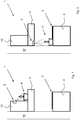
- FIG. 1 a first embodiment of the extractor hood 1 according to the invention is shown.
- the extractor hood 1 is a so-called box hood in the embodiment shown.
- the extractor hood 1 consists of a chimney 10 and a viewing hood 11 arranged below the chimney 10.
- the extractor hood 1 is mounted on the rear side on a wall W and the viewing hood 11 projects beyond the chimney 10 to the front.
- a hob 3 is shown below the extractor hood 1.
- the hob 3 is arranged in the top of a kitchen cabinet 4.
- a light module 2 is integrated in the extractor hood 1.
- the light module 2 is integrated into the front of the chimney 10 in such a way that it can emit light via the front of the chimney 10.
- the light module 2 is preferably designed or integrated in the extractor hood 1 in such a way that it can emit light obliquely downwards.
- the light emitted by the light module can thus be directed onto the upper side of the viewing hood 11 in the area that protrudes forward beyond the chimney 10. Is how in Figure 1 If a plant, for example herbs, is placed on the top of the viewing hood 11, the light from the light module 2 reaches the plant.
- the light module 2 can be designed so that it emits light in the wavelength range of 630-660nm, 400-520nm and 700-750nm, respectively.
- one or more light sources (not shown), in particular LEDs, can be accommodated in the light module 2.
- the second embodiment shown in Figure 2 is shown differs from the first embodiment in the arrangement of the light module 2 in the extractor hood 1.
- the light module 2 is also integrated in the extractor hood 1.
- the light module 2 is incorporated into the underside of the extractor hood 1.
- the light module 2 can be introduced into the underside of the viewing hood 11 behind a suction opening (not shown) of the extractor hood 1.
- the light module 2 is arranged and aligned in such a way that it emits light downwards.
- a plant P which is placed on the kitchen cabinet 4 behind the hob 3, for example, can be captured by the light and thus illuminated.
- the third embodiment of the extractor hood 1 shown in Figure 3 differs from the first and second embodiment on the one hand in that two light modules 2 are provided in the third embodiment.
- the light modules 2 in the third embodiment are not integrated into the extractor hood 1, but attached to it from the outside.
- the light module 2 is a separate component to the extractor hood 1. In the state shown, this component is attached to the wall W below the extractor hood 1. The component can, however, also be placed on the kitchen cabinet 4, for example.
- a light module which has growth-promoting LED (s), i.e. LED (s) by means of which plant growth can be promoted, and which irradiates a defined area with it.
- growth-promoting LED i.e. LED (s)
- the light module it is desirable to emit radiation only in the wavelengths in which plants absorb the energy. In this way, with the same power that is required to operate the light module, more "usable" light can be made available than with conventional lights, since light in the wavelengths between approx. 520 and 600 nm is not relevant for the growth of plants.
- LED chips and packages which can also be referred to as packages, are preferably used, which take on an equivalent function of lights that are used in greenhouses, for example, and thereby enable significantly smaller installation spaces and lower power requirements.
- the light module is preferably an LED-based component for use with extractor hoods.
- a defined area is irradiated in which a plant or for example a herb garden can be placed.
- the irradiation takes place mainly in the wavelengths 630-660nm, 400-520nm and 740nm.
- the light module is preferably designed in such a way that it can be configured for different areas of application using a modular system, that is to say can be used with different extractor hoods.
- the light module can be integrated into the extractor hood.
- the extractor hood can offer a defined storage space for the herb garden, for example.
- the component can be integrated into the chimney, which can also be referred to as a duct, of a classic box hood.
- the irradiation can be designed to irradiate a defined area on the kitchen worktop.
- the light module can be positioned on the underside of the extractor hood, for example.
- a light module can be used which is a structurally separate component from the extractor hood.
- the light module can preferably be controlled via the extractor hood.
- the present invention offers a number of advantages.
- another function is integrated into an existing device, namely the extractor hood.
- No additional device is required here, so there is no additional space requirement in the kitchen.
- the user can take the herbs required for the hotplates directly from a herb garden that is on, under or next to the hood.
Landscapes
- Engineering & Computer Science (AREA)
- Chemical & Material Sciences (AREA)
- Combustion & Propulsion (AREA)
- Mechanical Engineering (AREA)
- General Engineering & Computer Science (AREA)
- Non-Portable Lighting Devices Or Systems Thereof (AREA)
- Cultivation Of Plants (AREA)
- Led Device Packages (AREA)
Abstract
Description
- Die Erfindung betrifft eine Dunstabzugshaube mit Leuchtmodul.
- Bei Dunstabzugshauben ist es bekannt ein oder mehrere Leuchtmodule vorzusehen, um die Umgebung der Dunstabzugshaube, insbesondere den Raum unterhalb der Dunstabzugshaube, in dem sich in der Regel das Kochfeld befindet, auszuleuchten.
- Ein Nachteil liegt darin, dass dieses Licht nicht oder nur unzureichend für weitere Zwecke verwendet werden kann.
- Aufgabe der vorliegenden Erfindung ist es daher eine Dunstabzugshaube zu schaffen, bei der zusätzlich zum Ausleuchten des Kochfeldes für einen Kochvorgang und dem Absaugen von Dünsten und Wrasen eine weitere Funktion durch die Dunstabzugshaube ausgeführt werden kann.
- Die Aufgabe wird daher erfindungsgemäß gelöst durch eine Dunstabzugshaube mit mindestens einem Leuchtmodul. Die Dunstabzugshaube ist dadurch gekennzeichnet, dass das Leuchtmodul mindestens eine Lichtquelle aufweist und das Leuchtmodul Licht in einem begrenzten Wellenlängenbereich ausgibt.
- Als Leuchtmodul wird eine Komponente bezeichnet, die mindestens eine Lichtquelle aufweist und über die Licht ausgegeben werden kann. Das Leuchtmodul kann zusätzlich zu der Lichtquelle Befestigungsvorrichtungen, Steuervorrichtungen und/oder einen Netzanschluss aufweisen. Das Leuchtmodul kann mit einer Beleuchtungsvorrichtung, die an der Dunstabzugshaube zum Ausleuchten des Kochfeldes vorgesehen ist, kombiniert sein oder separat zu dieser Beleuchtungsvorrichtung vorliegen.
- Das Leuchtmodul gibt erfindungsgemäß Licht in einem begrenzten Wellenlängenbereich aus. Als begrenzter Wellenlängenbereich wird hierbei ein Wellenlängenbereich bezeichnet, der kleiner ist als der Wellenlängenbereich des sichtbaren Lichts, der in dem Bereich von 400nm bis 700nm liegt.
- Indem Licht in einem im Vergleich zu dem sichtbaren Bereich oder Spektrum geringeren Wellenlängenbereich von dem Leuchtmodul ausgegeben wird, kann eine Reihe von Vorteilen erzielt werden. Insbesondere kann das Licht zu Zwecken verwendet werden, die über das reine Ausleuchten eines Arbeitsbereiches hinausgehen. Insbesondere kann eine gezielte Wellenlänge ausgegeben werden, die beispielsweise für das Wachstum von Pflanzen oder die Photosynthese förderlich ist. Viele Benutzer verwenden zum Kochen gerne frische Kräuter und Gewürze. Diese werden in Töpfen oder anderen Gefäßen in der Küche aufbewahrt. Pflanzen werden in der Regel auf die Fensterbank gestellt, da diese Licht einer bestimmten Wellenlänge benötigen, um zu wachsen. Herkömmliche Dunsthaubenleuchten emittieren nicht in diesen Wellenlängenbereichen. Das Tageslichtspektrum deckt diese Wellenlängenbereiche ab, strahlt jedoch sehr breitbandig im kompletten sichtbaren Bereich. Daher ist das Nachbilden des Tageslichtspektrums mit einer Leuchte ineffizient und nicht geeignet um das Wachstum der Pflanzen zu fördern. Indem bei dem erfindungsgemäßen Leuchtmodul Licht in einem begrenzten Wellenlängenbereich ausgegeben wird, kann hingegen der Wellenlängenbereich so eingestellt sein, dass dieser gezielt zum Wachstum der Pflanzen beiträgt.
- Das Einstellen des begrenzten Wellenlängenbereiches kann durch optische Elemente in dem Leuchtmodul erfolgen. Beispielsweise können Filter eingesetzt werden.
- Vorzugsweise wird aber eine Lichtquelle verwendet, die Licht nur in dem oder den begrenzten Wellenlängenbereichen ausgibt. Hierdurch wird der Aufbau des Leuchtmoduls und damit der Dunstabzugshaube vereinfacht.
- Gemäß einer bevorzugten Ausführungsform stellt die Lichtquelle eine LED (Light Emitting Diode) dar. Diese Ausführungsform weist eine Reihe von Vorteilen auf. Insbesondere sind LEDs dazu geeignet Licht nur in einem bestimmten Wellenlängenbereich auszugeben. Zudem ist der Platzbedarf für diese Art von Lichtquellen gering. Schließlich ist die Wärmeentwicklung beim Betrieb einer solchen Lichtquelle gering, wodurch auf eine spezielle Kühlung in dem Leuchtmodul verzichtet werden kann. Hierdurch vereinfacht sich der Aufbau des Leuchtmoduls und damit der Dunstabzugshaube weiter.
- Gemäß einer bevorzugten Ausführungsform gibt das mindestens eine Leuchtmodul Licht in einem Wellenlängenbereich von 630-660nm, 400-520nm und / oder 700-750nm aus. Jeder dieser Bereiche kann von einer eigenen Lichtquelle ausgegeben werden. Insbesondere können mehrere LEDs in dem Leuchtmodul vorgesehen sein, wobei jede dieser LEDs Licht in einem der genannten Wellenlängenbereichen ausgibt. Diese LEDs können in dem Leuchtmodul separat vorgesehen sein oder in einem LED-Paket oder Package zusammengefasst sein. Die bevorzugten Wellenlängenbereiche sind insbesondere zur Wachstumsförderung von Pflanzen geeignet, da in diesen Bereichen insbesondere das Absorptionsspektrum von beispielsweise Chlorophyll liegt. Auch bei dieser Ausführungsform des Leuchtmoduls wird das Licht vorzugsweise nur in diesen Wellenlängenbereichen und nicht in dazwischenliegenden Wellenbereichen ausgegeben. Hierdurch wird eine Energieeinsparung gegenüber einer Lichtquelle, die Licht in einem breiteren Bereich, der die genannten engeren Bereiche einschließt, erzielt.
- Gemäß einer Ausführungsform ist das mindestens eine Leuchtmodul mit der Steuerung der Dunstabzugshaube verbunden. Die Steuerung der Dunstabzugshaube kann insbesondere einer Steuereinheit sein, mittels derer der Lüfter der Dunstabzugshaube und gegebenenfalls weitere Beleuchtungsvorrichtungen der Dunstabzugshaube angesteuert werden. Die Verbindung des Leuchtmoduls gemäß der vorliegenden Erfindung mit der Steuerung der Dunstabzugshaube kann kabelgebunden oder drahtlos sein. Über die Verbindung kann das Leuchtmodul angesteuert und insbesondere aktiviert oder deaktiviert werden. Indem das Leuchtmodul mit der Steuerung der Dunstabzugshaube verbunden ist, ist der Aufbau des Leuchtmoduls weiter vereinfacht. Insbesondere ist beispielsweise das Vorsehen einer eigenen Bedieneinheit für das Leuchtmodul nicht notwendig und stattdessen kann die Bedieneinheit der Dunstabzugshaube entsprechend modifiziert werden, um dem Benutzer die Möglichkeit zu geben, das Leuchtmodul über die Bedieneinheit zu Aktivieren oder zu Deaktivieren.
- Zusätzlich kann das Leuchtmodul auch mit der Stromversorgung der Dunstabzugshaube verbunden sein. Dies ist vorteilhaft, da insbesondere in Küchen die Steckdosen in der Regel bereits durch Küchengeräte besetzt sind.
- Gemäß einer Ausführungsform ist das mindestens eine Leuchtmodul in die Dunstabzugshaube integriert. Als in die Dunstabzugshaube integriert wird ein Leuchtmodul bezeichnet, das in einer Aussparung der Dunstabzugshaube zumindest teilweise eingebracht ist. Insbesondere kann die Aussparung zur Aufnahme eines Gehäuses des Leuchtmoduls dienen.
- Zusätzlich oder alternativ kann das mindestens eine Leuchtmodul an der Dunstabzugshaube befestigt sein. Hierbei kann die Befestigung eine lösbare Befestigung darstellen. Beispielsweise kann das Leuchtmodul in eine dafür vorgesehen Aussparung an der Dunstabzugshaube eingeschoben und verrastet werden. Alternativ kann das Leuchtmodul an der Außenseite der Dunstabzugshaube befestigt werden. Beispielsweise kann das Leuchtmodul mittels Magneten an der Dunstabzugshaube gehalten werden.
- Ein Vorteil des Integrierens des Leuchtmoduls in die Dunstabzugshaube oder der Befestigung des Leuchtmoduls an der Dunstabzugshaube ist insbesondere, dass Licht in der Nähe der Dunstabzugshaube ausgegeben werden kann. Die Pflanzen, die mit diesem Licht versorgt werden sollen, können somit in der Nähe des Kochfeldes stehen und somit vom Benutzer während des Kochvorgangs auf einfache Weise erreicht werden.
- Erfindungsgemäß ist es auch möglich, dass das mindestens eine Leuchtmodul eine zu der Dunstabzugshaube separate Komponente darstellt. Als separate Komponente wird eine Komponente bezeichnet, die nicht zur Befestigung an der Dunstabzugshaube ausgelegt ist. Diese separate Komponente kann daher unabhängig von der Dunstabzugshaube in der Küche platziert werden. Bei dieser Ausführungsform ist aber das Leuchtmodul vorzugsweise zumindest mit der Steuerung der Dunstabzugshaube verbunden. Hierdurch kann der Aufbau des Leuchtmoduls vereinfacht sein.
- Gemäß einer Ausführungsform liegt das Leuchtmodul an der Dunstabzugshaube in einer Höhe oberhalb der Sichthaube. Bei dieser Ausführungsform kann das Leuchtmodul beispielsweise in einen Kamin der Dunstabzugshaube integriert sein und Licht nach vorne oder zu zumindest einer Seite abgeben. Hierdurch kann eine Pflanze, die auf der Oberseite der Sichthaube, beispielsweise einer Box-Sichthaube abgestellt wird von dem Leuchtmodul mit Licht in der gewünschten Wellenlänge versorgen. Alternativ kann das Leuchtmodul an dem Kamin befestigt werden oder auf die Sichthaube gestellt werden. Auch bei diesen Ausführungsformen, bei denen das Leuchtmodul nicht in die Dunstabzugshaube integriert ist, kann eine Pflanze, die auf der Sichthaube abgestellt ist, mit Licht in der gewünschten Wellenlänge versorgt werden.
- Gemäß einer weiteren Ausführungsform liegt mindestens ein Leuchtmodul an der Unterseite der Dunstabzugshaube. Auch bei dieser Ausführungsform kann das Leuchtmodul in der Dunstabzugshaube integriert sein oder an der Dunstabzugshaube befestigt sein. Durch die Anordnung des Leuchtmoduls an der Unterseite können Pflanzen, die hinter oder neben dem Kochfeld stehen zuverlässig mit dem gewünschten Licht beleuchtet werden.
- Gemäß einer Ausführungsform ist mindestens ein Leuchtmodul schwenkbar an der Dunstabzugshaube befestigt. Auch bei dieser Ausführungsform kann das Leuchtmodul in der Dunstabzugshaube integriert sein oder an der Dunstabzugshaube befestigt sein. Durch die schwenkbare Befestigung kann die Ausrichtung des Leuchtmoduls der aktuellen Position einer Pflanze angepasst werden.
- Die vorliegende Erfindung wird im Folgenden erneut unter Bezugnahme auf die beiliegenden Figuren beschrieben. Es zeigen:
-
Figur 1 : eine schematische Darstellung einer ersten Ausführungsform der erfindungsgemäßen Dunstabzugshaube; -
Figur 2 : eine schematische Darstellung einer zweiten Ausführungsform der erfindungsgemäßen Dunstabzugshaube; -
Figur 3 : eine schematische Darstellung einer dritten Ausführungsform der erfindungsgemäßen Dunstabzugshaube; und -
Figur 4 : eine schematische Darstellung einer vierten Ausführungsform der erfindungsgemäßen Dunstabzugshaube. - In
Figur 1 ist eine erste Ausführungsform der erfindungsgemäßen Dunstabzugshaube 1 gezeigt. Die Dunstabzugshaube 1 stellt in der dargestellten Ausführungsform eine sogenannte Box-Haube dar. Die Dunstabzugshaube 1 besteht aus einem Kamin 10 und einer unterhalb des Kamins 10 angeordneten Sichthaube 11. Die Dunstabzugshaube 1 ist an der Rückseite an einer Wand W montiert und die Sichthaube 11 überragt den Kamin 10 nach vorne. - Unterhalb der Dunstabzugshaube 1 ist ein Kochfeld 3 gezeigt. Das Kochfeld 3 ist in der Oberseite eines Küchenschrankes 4 angeordnet.
- Bei der ersten Ausführungsform ist in der Dunstabzugshaube 1 ein Leuchtmodul 2 integriert. Das Leuchtmodul 2 ist in der Vorderseite des Kamins 10 so integriert, dass dieses Licht über die Vorderseite des Kamins 10 abgeben kann. Vorzugsweise bei dieser Ausführungsform ist das Leuchtmodul 2 so ausgelegt oder so in der Dunstabzugshaube 1 integrierte, dass dieses Licht schräg nach unten abgeben kann. Wie in der
Figur 1 gezeigt, kann somit das von dem Leuchtmodul abgegebene Licht auf die Oberseite der Sichthaube 11 in dem Bereich gerichtet werden, der über den Kamin 10 nach vorne übersteht. Ist, wie inFigur 1 angedeutet auf der Oberseite der Sichthaube 11 eine Pflanze, beispielsweise Kräuter, platziert, so erreicht das Licht des Leuchtmoduls 2 die Pflanze. Das Leuchtmodul 2 kann so ausgelegt sein, dass dieses beispielsweise Licht im Wellenlängenbereich von jeweils 630-660nm, 400-520nm und 700- 750nm abgibt. Hierzu können in dem Leuchtmodul 2 eine oder mehrere Lichtquellen (nicht gezeigt), insbesondere LEDs, aufgenommen sein. - Die zweite Ausführungsform, die in
Figur 2 gezeigt ist, unterscheidet sich von der ersten Ausführungsform durch die Anordnung des Leuchtmoduls 2 in der Dunstabzugshaube 1. Auch bei der zweiten Ausführungsform ist das Leuchtmodul 2 in der Dunstabzugshaube 1 integriert. Allerdings ist das Leuchtmodul 2 in die Unterseite der Dunstabzugshaube 1 eingebracht. Beispielsweise kann das Leuchtmodul 2 hinter einer Ansaugöffnung (nicht gezeigt) der Dunstabzugshaube 1 in die Unterseite der Sichthaube 11 eingebracht sein. Das Leuchtmodul 2 ist dabei so angeordnet und ausgerichtet, dass dieses Licht nach unten abgibt. Hierdurch kann eine Pflanze P, die beispielsweise hinter dem Kochfeld 3 auf dem Küchenschrank 4 platziert wird, von dem Licht erfasst und damit beleuchtet werden. - Die dritte Ausführungsform der Dunstabzugshaube 1, die in
Figur 3 gezeigt ist, unterscheidet sich von der ersten und zweiten Ausführungsform zum einen dadurch, dass bei der dritten Ausführungsform zwei Leuchtmodule 2 vorgesehen sind. Zum anderen sind die Leuchtmodule 2 bei der dritten Ausführungsform nicht in die Dunstabzugshaube 1 integriert, sondern an dieser von außen befestigt. - In der vierten Ausführungsform, die in
Figur 4 gezeigt ist, ist das Leuchtmodul 2 eine zu der Dunstabzugshaube 1 separate Komponente. In dem gezeigten Zustand ist diese Komponente an der Wand W unterhalb der Dunstabzugshaube 1 befestigt. Die Komponente kann allerdings beispielsweise auch auf den Küchenschrank 4 gestellt werden. - Bei der erfindungsgemäßen Dunstabzugshaube wird vorzugsweise ein Leuchtmodul verwendet, das wachstumsfördernde LED (s), das heißt LED(s) mittels derer das Pflanzenwachstum gefördert werden kann, aufweist und das einen definierten Bereich damit bestrahlt.
- Herkömmliche Leuchten, die in Dunsthauben verwendet werden, beispielsweise Glühbirnen, emittieren nahezu über dem gesamten Bereich der sichtbaren Wellenlänge. Ziel dieser herkömmlichen Leuchten, ist es dass die Farbe nahe der "Black Body Curve" zwischen -2500K und 5000 K im CIE Diagramm liegt, um ein weißes Licht zu erzeugen.
- Bei dem erfindungsgemäßen Leuchtmodul ist es gewünscht möglichst nur in den Wellenlängen abzustrahlen, in denen Pflanzen die Energie absorbieren. Hierdurch kann man mit der gleichen Leistung, die zum Betreiben des Leuchtmoduls erforderlich ist, mehr "nutzbares" Licht zur Verfügung stellen als bei herkömmlichen Leuchten, da Licht in den Wellenlängen zwischen ca. 520 und 600 nm für das Wachstum der Pflanzen nicht relevant ist.
- Bei der vorliegenden Erfindung werden vorzugsweise LED-Chips und Pakete, die auch als Packages bezeichnet werden können, verwendet, die eine gleichwertige Funktion von Leuchten, die beispielsweise in Gewächshäusern verwendet werden, übernehmen und dabei wesentlich kleinere Bauräume und einen geringeren Leistungsbedarf ermöglichen.
- Bei der vorliegenden Erfindung handelt es sich bei dem Leuchtmodul vorzugsweise um eine LED-basierte Komponente zur Verwendung mit Dunstabzugshauben. Mit dieser Komponente wird ein definierter Bereich bestrahlt, in dem eine Pflanze oder beispielsweise ein Kräutergarten platziert werden kann. Die Bestrahlung erfolgt hierbei hauptsächlich in den Wellenlängen 630-660nm, 400-520nm sowie 740nm.
- Das Leuchtmodul ist vorzugsweise so ausgelegt, dass es durch ein Baukastensystem auf unterschiedliche Anwendungsbereiche, konfiguriert werden kann, das heißt mit unterschiedlichen Dunstabzugshauben verwendet werden kann.
- Beispielsweise kann das Leuchtmodul in die Dunstabzugshaube integriert werden. Die Dunstabzugshaube kann dabei einen definierten Ablageplatz für beispielsweise den Kräutergarten bieten. Beispielsweise kann die Komponente in dem Kamin, der auch als Kanal bezeichnet werden kann einer klassischen Box-Haube integriert werden.
- Alternativ oder zusätzlich kann die Bestrahlung auf eine Bestrahlung einer definierten Fläche auf der Arbeitsplatte der Küche ausgelegt werden. Hierzu kann das Leuchtmodul beispielsweise an der Unterseite der Dunstabzugshaube positioniert werden.
- Weiterhin kann alternativ oder zusätzlich ein Leuchtmodul verwendet werden, das eine baulich von der Dunstabzugshaube separate Komponente darstellt. Bei dieser Ausführungsform kann das Leuchtmodul aber vorzugsweise über die Dunstabzugshaube angesteuert werden.
- Die vorliegende Erfindung bietet eine Reihe von Vorteilen. Zum einen ist für den Benutzer neben der Lüfter- und normalen Beleuchtungsfunktion der Dunstabzugshaube eine weitere Funktion in ein vorhandenes Gerät, nämlich die Dunstabzugshaube, integriert. Hierbei wird kein Zusatzgerät benötigt und somit entsteht kein zusätzlicher Platzbedarf in der Küche. Zudem kann der Benutzer die an den Kochstellen benötigten Kräuter direkt aus einem Kräutergarten entnehmen, der auf, unter oder neben der Haube steht.
-
- 1
- Dunstabzugshaube
- 10
- Kamin
- 11
- Sichthaube
- 2
- Leuchtmodul
- 3
- Kochfeld
- 4
- Küchenschrank
- P
- Pflanze
- W
- Wand
Claims (10)
- Dunstabzugshaube mit mindestens einem Leuchtmodul (2), dadurch gekennzeichnet, dass das Leuchtmodul (2) mindestens eine Lichtquelle aufweist und das Leuchtmodul (2) Licht in einem begrenzten Wellenlängenbereich ausgibt.
- Dunstabzugshaube nach Anspruch 1, dadurch gekennzeichnet, dass die Lichtquelle eine LED darstellt.
- Dunstabzugshaube nach einem der Ansprüche 1 oder 2, dadurch gekennzeichnet, dass das mindestens eine Leuchtmodul (2) Licht in einem Wellenlängenbereich von 630-660nm, 400-520nm und/oder 700- 750nm ausgibt.
- Dunstabzugshaube nach einem der Ansprüche 1 bis 3, dadurch gekennzeichnet, dass das mindestens eine Leuchtmodul (2) mit der Steuerung der Dunstabzugshaube (1) verbunden ist.
- Dunstabzugshaube nach einem der Ansprüche 1 bis 4, dadurch gekennzeichnet, dass das mindestens eine Leuchtmodul (2) in die Dunstabzugshaube (2) integriert ist.
- Dunstabzugshaube nach einem der Ansprüche 1 bis 5, dadurch gekennzeichnet, dass mindestens eine Leuchtmodul (2) an der Dunstabzugshaube (1) befestigt ist.
- Dunstabzugshaube nach einem der Ansprüche 1 bis 4, dadurch gekennzeichnet, dass das mindestens eine Leuchtmodul (2) eine zu der Dunstabzugshaube (1) separate Komponente darstellt.
- Dunstabzugshaube nach einem der Ansprüche 1 bis 7, dadurch gekennzeichnet, dass die Dunstabzugshaube (1) eine Sichthaube (11) aufweist und mindestens ein Leuchtmodul (2) an der Dunstabzugshaube (1) in einer Höhe oberhalb der Sichthaube (11) liegt.
- Dunstabzugshaube nach einem der Ansprüche 1 bis 8, dadurch gekennzeichnet, dass mindestens ein Leuchtmodul (2) an der Unterseite der Dunstabzugshaube (1) liegt.
- Dunstabzugshaube nach einem der Ansprüche 1 bis 9, dadurch gekennzeichnet, dass mindestens ein Leuchtmodul (2) schwenkbar an der Dunstabzugshaube (1) befestigt ist.
Applications Claiming Priority (1)
| Application Number | Priority Date | Filing Date | Title |
|---|---|---|---|
| DE102019202421.1A DE102019202421A1 (de) | 2019-02-22 | 2019-02-22 | Dunstabzugshaube mit Leuchtmodul |
Publications (2)
| Publication Number | Publication Date |
|---|---|
| EP3699496A1 true EP3699496A1 (de) | 2020-08-26 |
| EP3699496B1 EP3699496B1 (de) | 2023-08-02 |
Family
ID=69326354
Family Applications (1)
| Application Number | Title | Priority Date | Filing Date |
|---|---|---|---|
| EP20153759.4A Active EP3699496B1 (de) | 2019-02-22 | 2020-01-27 | Dunstabzugshaube mit leuchtmodul |
Country Status (2)
| Country | Link |
|---|---|
| EP (1) | EP3699496B1 (de) |
| DE (1) | DE102019202421A1 (de) |
Citations (3)
| Publication number | Priority date | Publication date | Assignee | Title |
|---|---|---|---|---|
| DE102005060359A1 (de) * | 2005-12-16 | 2007-06-21 | BSH Bosch und Siemens Hausgeräte GmbH | Haushaltsgerät für Küche |
| DE202009013432U1 (de) * | 2009-10-05 | 2010-03-11 | Homeier Küchentechnik GmbH | Luftreinigungseinrichtung |
| EP2905544A1 (de) * | 2014-02-10 | 2015-08-12 | Electrolux Appliances Aktiebolag | Küchenabzugshaube für Phototherapie mit einer Lichtquelle mit hoher Lichtintensität |
-
2019
- 2019-02-22 DE DE102019202421.1A patent/DE102019202421A1/de not_active Withdrawn
-
2020
- 2020-01-27 EP EP20153759.4A patent/EP3699496B1/de active Active
Patent Citations (3)
| Publication number | Priority date | Publication date | Assignee | Title |
|---|---|---|---|---|
| DE102005060359A1 (de) * | 2005-12-16 | 2007-06-21 | BSH Bosch und Siemens Hausgeräte GmbH | Haushaltsgerät für Küche |
| DE202009013432U1 (de) * | 2009-10-05 | 2010-03-11 | Homeier Küchentechnik GmbH | Luftreinigungseinrichtung |
| EP2905544A1 (de) * | 2014-02-10 | 2015-08-12 | Electrolux Appliances Aktiebolag | Küchenabzugshaube für Phototherapie mit einer Lichtquelle mit hoher Lichtintensität |
Also Published As
| Publication number | Publication date |
|---|---|
| EP3699496B1 (de) | 2023-08-02 |
| DE102019202421A1 (de) | 2020-08-27 |
Similar Documents
| Publication | Publication Date | Title |
|---|---|---|
| AT16807U1 (de) | Beleuchtungsanordnung | |
| EP1963749A1 (de) | Haushaltsgerät für küche | |
| EP3296644B1 (de) | Küchengerät mit kochfeld und dunstabzugsvorrichtung | |
| EP2857754B1 (de) | Haushaltsgerät | |
| DE102012218002B4 (de) | Gargerät und Verfahren zum Betreiben eines Gargeräts | |
| DE102015102303A1 (de) | Haushaltgerätesystem und Verfahren zum Betreiben | |
| DE202021104434U1 (de) | Operative Beleuchtungsvorrichtung | |
| EP2932932B1 (de) | Medizinische Leuchte | |
| EP3699496B1 (de) | Dunstabzugshaube mit leuchtmodul | |
| DE102015101099B4 (de) | Dunstabzugshaube | |
| DE102011114993A1 (de) | Laborabzug und insbesondere Sicherheitswerkbank mit LED-Beleuchtung | |
| EP3138386B1 (de) | Pflanzen-aufzuchtschrank | |
| WO2019086281A1 (de) | Gargerät mit einer beleuchtungsvorrichtung zur erzeugung eines gehäuseexternen brennpunkts | |
| DE102010063750B4 (de) | Dunstabzugshaube mit Leuchtmodul | |
| CH700022B1 (de) | Stehleuchte. | |
| EP3396242B1 (de) | Lichtstrahler sowie lichstrahlersystem und arbeitsplatzmöbel mit einem solchen | |
| DE102020122209A1 (de) | Operationsleuchte | |
| DE102022100499B4 (de) | Dunstabzugshaube | |
| EP3703501B1 (de) | Gargerät mit einer beleuchtungsvorrichtung zum abstrahlen von lichtstrahlen | |
| WO2018206240A1 (de) | Beleuchtungsvorrichtung für haushaltsgerät und haushaltsgerät | |
| DE202021101450U1 (de) | Stehleuchte mit UV-Lichtquelle | |
| DE102009026514A1 (de) | Dunstabzugsvorrichtung | |
| DE102015225859A1 (de) | Gargerät | |
| EP2937634B1 (de) | Dunstabzughaube mit Auszugelement und Beleuchtungseinheit | |
| DE202021103900U1 (de) | Beleuchtungsvorrichtung zur Desinfektion von Luft mit ultraviolettem Licht und zur Umgebungsbeleuchtung |
Legal Events
| Date | Code | Title | Description |
|---|---|---|---|
| PUAI | Public reference made under article 153(3) epc to a published international application that has entered the european phase |
Free format text: ORIGINAL CODE: 0009012 |
|
| STAA | Information on the status of an ep patent application or granted ep patent |
Free format text: STATUS: THE APPLICATION HAS BEEN PUBLISHED |
|
| AK | Designated contracting states |
Kind code of ref document: A1 Designated state(s): AL AT BE BG CH CY CZ DE DK EE ES FI FR GB GR HR HU IE IS IT LI LT LU LV MC MK MT NL NO PL PT RO RS SE SI SK SM TR |
|
| AX | Request for extension of the european patent |
Extension state: BA ME |
|
| STAA | Information on the status of an ep patent application or granted ep patent |
Free format text: STATUS: REQUEST FOR EXAMINATION WAS MADE |
|
| 17P | Request for examination filed |
Effective date: 20210226 |
|
| RBV | Designated contracting states (corrected) |
Designated state(s): AL AT BE BG CH CY CZ DE DK EE ES FI FR GB GR HR HU IE IS IT LI LT LU LV MC MK MT NL NO PL PT RO RS SE SI SK SM TR |
|
| GRAP | Despatch of communication of intention to grant a patent |
Free format text: ORIGINAL CODE: EPIDOSNIGR1 |
|
| STAA | Information on the status of an ep patent application or granted ep patent |
Free format text: STATUS: GRANT OF PATENT IS INTENDED |
|
| RIC1 | Information provided on ipc code assigned before grant |
Ipc: A01G 7/04 20060101ALI20230223BHEP Ipc: F24C 15/20 20060101AFI20230223BHEP |
|
| INTG | Intention to grant announced |
Effective date: 20230321 |
|
| GRAS | Grant fee paid |
Free format text: ORIGINAL CODE: EPIDOSNIGR3 |
|
| GRAA | (expected) grant |
Free format text: ORIGINAL CODE: 0009210 |
|
| STAA | Information on the status of an ep patent application or granted ep patent |
Free format text: STATUS: THE PATENT HAS BEEN GRANTED |
|
| AK | Designated contracting states |
Kind code of ref document: B1 Designated state(s): AL AT BE BG CH CY CZ DE DK EE ES FI FR GB GR HR HU IE IS IT LI LT LU LV MC MK MT NL NO PL PT RO RS SE SI SK SM TR |
|
| REG | Reference to a national code |
Ref country code: GB Ref legal event code: FG4D Free format text: NOT ENGLISH |
|
| REG | Reference to a national code |
Ref country code: CH Ref legal event code: EP |
|
| REG | Reference to a national code |
Ref country code: DE Ref legal event code: R096 Ref document number: 502020004429 Country of ref document: DE |
|
| REG | Reference to a national code |
Ref country code: IE Ref legal event code: FG4D Free format text: LANGUAGE OF EP DOCUMENT: GERMAN |
|
| REG | Reference to a national code |
Ref country code: LT Ref legal event code: MG9D |
|
| REG | Reference to a national code |
Ref country code: NL Ref legal event code: MP Effective date: 20230802 |
|
| PG25 | Lapsed in a contracting state [announced via postgrant information from national office to epo] |
Ref country code: GR Free format text: LAPSE BECAUSE OF FAILURE TO SUBMIT A TRANSLATION OF THE DESCRIPTION OR TO PAY THE FEE WITHIN THE PRESCRIBED TIME-LIMIT Effective date: 20231103 |
|
| PG25 | Lapsed in a contracting state [announced via postgrant information from national office to epo] |
Ref country code: IS Free format text: LAPSE BECAUSE OF FAILURE TO SUBMIT A TRANSLATION OF THE DESCRIPTION OR TO PAY THE FEE WITHIN THE PRESCRIBED TIME-LIMIT Effective date: 20231202 |
|
| PG25 | Lapsed in a contracting state [announced via postgrant information from national office to epo] |
Ref country code: SE Free format text: LAPSE BECAUSE OF FAILURE TO SUBMIT A TRANSLATION OF THE DESCRIPTION OR TO PAY THE FEE WITHIN THE PRESCRIBED TIME-LIMIT Effective date: 20230802 Ref country code: RS Free format text: LAPSE BECAUSE OF FAILURE TO SUBMIT A TRANSLATION OF THE DESCRIPTION OR TO PAY THE FEE WITHIN THE PRESCRIBED TIME-LIMIT Effective date: 20230802 Ref country code: PT Free format text: LAPSE BECAUSE OF FAILURE TO SUBMIT A TRANSLATION OF THE DESCRIPTION OR TO PAY THE FEE WITHIN THE PRESCRIBED TIME-LIMIT Effective date: 20231204 Ref country code: NO Free format text: LAPSE BECAUSE OF FAILURE TO SUBMIT A TRANSLATION OF THE DESCRIPTION OR TO PAY THE FEE WITHIN THE PRESCRIBED TIME-LIMIT Effective date: 20231102 Ref country code: NL Free format text: LAPSE BECAUSE OF FAILURE TO SUBMIT A TRANSLATION OF THE DESCRIPTION OR TO PAY THE FEE WITHIN THE PRESCRIBED TIME-LIMIT Effective date: 20230802 Ref country code: LV Free format text: LAPSE BECAUSE OF FAILURE TO SUBMIT A TRANSLATION OF THE DESCRIPTION OR TO PAY THE FEE WITHIN THE PRESCRIBED TIME-LIMIT Effective date: 20230802 Ref country code: LT Free format text: LAPSE BECAUSE OF FAILURE TO SUBMIT A TRANSLATION OF THE DESCRIPTION OR TO PAY THE FEE WITHIN THE PRESCRIBED TIME-LIMIT Effective date: 20230802 Ref country code: IS Free format text: LAPSE BECAUSE OF FAILURE TO SUBMIT A TRANSLATION OF THE DESCRIPTION OR TO PAY THE FEE WITHIN THE PRESCRIBED TIME-LIMIT Effective date: 20231202 Ref country code: HR Free format text: LAPSE BECAUSE OF FAILURE TO SUBMIT A TRANSLATION OF THE DESCRIPTION OR TO PAY THE FEE WITHIN THE PRESCRIBED TIME-LIMIT Effective date: 20230802 Ref country code: GR Free format text: LAPSE BECAUSE OF FAILURE TO SUBMIT A TRANSLATION OF THE DESCRIPTION OR TO PAY THE FEE WITHIN THE PRESCRIBED TIME-LIMIT Effective date: 20231103 Ref country code: FI Free format text: LAPSE BECAUSE OF FAILURE TO SUBMIT A TRANSLATION OF THE DESCRIPTION OR TO PAY THE FEE WITHIN THE PRESCRIBED TIME-LIMIT Effective date: 20230802 |
|
| PG25 | Lapsed in a contracting state [announced via postgrant information from national office to epo] |
Ref country code: PL Free format text: LAPSE BECAUSE OF FAILURE TO SUBMIT A TRANSLATION OF THE DESCRIPTION OR TO PAY THE FEE WITHIN THE PRESCRIBED TIME-LIMIT Effective date: 20230802 |
|
| PG25 | Lapsed in a contracting state [announced via postgrant information from national office to epo] |
Ref country code: ES Free format text: LAPSE BECAUSE OF FAILURE TO SUBMIT A TRANSLATION OF THE DESCRIPTION OR TO PAY THE FEE WITHIN THE PRESCRIBED TIME-LIMIT Effective date: 20230802 |
|
| PG25 | Lapsed in a contracting state [announced via postgrant information from national office to epo] |
Ref country code: SM Free format text: LAPSE BECAUSE OF FAILURE TO SUBMIT A TRANSLATION OF THE DESCRIPTION OR TO PAY THE FEE WITHIN THE PRESCRIBED TIME-LIMIT Effective date: 20230802 Ref country code: RO Free format text: LAPSE BECAUSE OF FAILURE TO SUBMIT A TRANSLATION OF THE DESCRIPTION OR TO PAY THE FEE WITHIN THE PRESCRIBED TIME-LIMIT Effective date: 20230802 Ref country code: ES Free format text: LAPSE BECAUSE OF FAILURE TO SUBMIT A TRANSLATION OF THE DESCRIPTION OR TO PAY THE FEE WITHIN THE PRESCRIBED TIME-LIMIT Effective date: 20230802 Ref country code: EE Free format text: LAPSE BECAUSE OF FAILURE TO SUBMIT A TRANSLATION OF THE DESCRIPTION OR TO PAY THE FEE WITHIN THE PRESCRIBED TIME-LIMIT Effective date: 20230802 Ref country code: DK Free format text: LAPSE BECAUSE OF FAILURE TO SUBMIT A TRANSLATION OF THE DESCRIPTION OR TO PAY THE FEE WITHIN THE PRESCRIBED TIME-LIMIT Effective date: 20230802 Ref country code: CZ Free format text: LAPSE BECAUSE OF FAILURE TO SUBMIT A TRANSLATION OF THE DESCRIPTION OR TO PAY THE FEE WITHIN THE PRESCRIBED TIME-LIMIT Effective date: 20230802 Ref country code: SK Free format text: LAPSE BECAUSE OF FAILURE TO SUBMIT A TRANSLATION OF THE DESCRIPTION OR TO PAY THE FEE WITHIN THE PRESCRIBED TIME-LIMIT Effective date: 20230802 |
|
| REG | Reference to a national code |
Ref country code: DE Ref legal event code: R097 Ref document number: 502020004429 Country of ref document: DE |
|
| PG25 | Lapsed in a contracting state [announced via postgrant information from national office to epo] |
Ref country code: IT Free format text: LAPSE BECAUSE OF FAILURE TO SUBMIT A TRANSLATION OF THE DESCRIPTION OR TO PAY THE FEE WITHIN THE PRESCRIBED TIME-LIMIT Effective date: 20230802 |
|
| PLBE | No opposition filed within time limit |
Free format text: ORIGINAL CODE: 0009261 |
|
| STAA | Information on the status of an ep patent application or granted ep patent |
Free format text: STATUS: NO OPPOSITION FILED WITHIN TIME LIMIT |
|
| 26N | No opposition filed |
Effective date: 20240503 |
|
| PG25 | Lapsed in a contracting state [announced via postgrant information from national office to epo] |
Ref country code: SI Free format text: LAPSE BECAUSE OF FAILURE TO SUBMIT A TRANSLATION OF THE DESCRIPTION OR TO PAY THE FEE WITHIN THE PRESCRIBED TIME-LIMIT Effective date: 20230802 |
|
| PG25 | Lapsed in a contracting state [announced via postgrant information from national office to epo] |
Ref country code: MC Free format text: LAPSE BECAUSE OF FAILURE TO SUBMIT A TRANSLATION OF THE DESCRIPTION OR TO PAY THE FEE WITHIN THE PRESCRIBED TIME-LIMIT Effective date: 20230802 |
|
| PG25 | Lapsed in a contracting state [announced via postgrant information from national office to epo] |
Ref country code: MC Free format text: LAPSE BECAUSE OF FAILURE TO SUBMIT A TRANSLATION OF THE DESCRIPTION OR TO PAY THE FEE WITHIN THE PRESCRIBED TIME-LIMIT Effective date: 20230802 |
|
| REG | Reference to a national code |
Ref country code: CH Ref legal event code: PL |
|
| PG25 | Lapsed in a contracting state [announced via postgrant information from national office to epo] |
Ref country code: LU Free format text: LAPSE BECAUSE OF NON-PAYMENT OF DUE FEES Effective date: 20240127 |
|
| GBPC | Gb: european patent ceased through non-payment of renewal fee |
Effective date: 20240127 |
|
| PG25 | Lapsed in a contracting state [announced via postgrant information from national office to epo] |
Ref country code: LU Free format text: LAPSE BECAUSE OF NON-PAYMENT OF DUE FEES Effective date: 20240127 |
|
| PG25 | Lapsed in a contracting state [announced via postgrant information from national office to epo] |
Ref country code: GB Free format text: LAPSE BECAUSE OF NON-PAYMENT OF DUE FEES Effective date: 20240127 |
|
| PG25 | Lapsed in a contracting state [announced via postgrant information from national office to epo] |
Ref country code: BE Free format text: LAPSE BECAUSE OF NON-PAYMENT OF DUE FEES Effective date: 20240131 |
|
| PG25 | Lapsed in a contracting state [announced via postgrant information from national office to epo] |
Ref country code: FR Free format text: LAPSE BECAUSE OF NON-PAYMENT OF DUE FEES Effective date: 20240131 |
|
| PG25 | Lapsed in a contracting state [announced via postgrant information from national office to epo] |
Ref country code: CH Free format text: LAPSE BECAUSE OF NON-PAYMENT OF DUE FEES Effective date: 20240131 |
|
| PG25 | Lapsed in a contracting state [announced via postgrant information from national office to epo] |
Ref country code: GB Free format text: LAPSE BECAUSE OF NON-PAYMENT OF DUE FEES Effective date: 20240127 Ref country code: FR Free format text: LAPSE BECAUSE OF NON-PAYMENT OF DUE FEES Effective date: 20240131 Ref country code: CH Free format text: LAPSE BECAUSE OF NON-PAYMENT OF DUE FEES Effective date: 20240131 Ref country code: BE Free format text: LAPSE BECAUSE OF NON-PAYMENT OF DUE FEES Effective date: 20240131 |
|
| REG | Reference to a national code |
Ref country code: BE Ref legal event code: MM Effective date: 20240131 |
|
| PG25 | Lapsed in a contracting state [announced via postgrant information from national office to epo] |
Ref country code: BG Free format text: LAPSE BECAUSE OF FAILURE TO SUBMIT A TRANSLATION OF THE DESCRIPTION OR TO PAY THE FEE WITHIN THE PRESCRIBED TIME-LIMIT Effective date: 20230802 |
|
| PG25 | Lapsed in a contracting state [announced via postgrant information from national office to epo] |
Ref country code: BG Free format text: LAPSE BECAUSE OF FAILURE TO SUBMIT A TRANSLATION OF THE DESCRIPTION OR TO PAY THE FEE WITHIN THE PRESCRIBED TIME-LIMIT Effective date: 20230802 |
|
| PG25 | Lapsed in a contracting state [announced via postgrant information from national office to epo] |
Ref country code: IE Free format text: LAPSE BECAUSE OF NON-PAYMENT OF DUE FEES Effective date: 20240127 |
|
| PG25 | Lapsed in a contracting state [announced via postgrant information from national office to epo] |
Ref country code: IE Free format text: LAPSE BECAUSE OF NON-PAYMENT OF DUE FEES Effective date: 20240127 |
|
| PGFP | Annual fee paid to national office [announced via postgrant information from national office to epo] |
Ref country code: AT Payment date: 20250417 Year of fee payment: 5 |
|
| PG25 | Lapsed in a contracting state [announced via postgrant information from national office to epo] |
Ref country code: CY Free format text: LAPSE BECAUSE OF FAILURE TO SUBMIT A TRANSLATION OF THE DESCRIPTION OR TO PAY THE FEE WITHIN THE PRESCRIBED TIME-LIMIT; INVALID AB INITIO Effective date: 20200127 |
|
| PG25 | Lapsed in a contracting state [announced via postgrant information from national office to epo] |
Ref country code: HU Free format text: LAPSE BECAUSE OF FAILURE TO SUBMIT A TRANSLATION OF THE DESCRIPTION OR TO PAY THE FEE WITHIN THE PRESCRIBED TIME-LIMIT; INVALID AB INITIO Effective date: 20200127 |
|
| PG25 | Lapsed in a contracting state [announced via postgrant information from national office to epo] |
Ref country code: TR Free format text: LAPSE BECAUSE OF FAILURE TO SUBMIT A TRANSLATION OF THE DESCRIPTION OR TO PAY THE FEE WITHIN THE PRESCRIBED TIME-LIMIT Effective date: 20230802 |
|
| REG | Reference to a national code |
Ref country code: AT Ref legal event code: MM01 Ref document number: 1595158 Country of ref document: AT Kind code of ref document: T Effective date: 20250127 |
|
| PGFP | Annual fee paid to national office [announced via postgrant information from national office to epo] |
Ref country code: DE Payment date: 20260131 Year of fee payment: 7 |
|
| PG25 | Lapsed in a contracting state [announced via postgrant information from national office to epo] |
Ref country code: AT Free format text: LAPSE BECAUSE OF NON-PAYMENT OF DUE FEES Effective date: 20250127 |