EP3698983B1 - Tire - Google Patents
Tire Download PDFInfo
- Publication number
- EP3698983B1 EP3698983B1 EP18867986.4A EP18867986A EP3698983B1 EP 3698983 B1 EP3698983 B1 EP 3698983B1 EP 18867986 A EP18867986 A EP 18867986A EP 3698983 B1 EP3698983 B1 EP 3698983B1
- Authority
- EP
- European Patent Office
- Prior art keywords
- tire
- central
- width direction
- block land
- outer side
- Prior art date
- Legal status (The legal status is an assumption and is not a legal conclusion. Google has not performed a legal analysis and makes no representation as to the accuracy of the status listed.)
- Active
Links
Images

Classifications
-
- B—PERFORMING OPERATIONS; TRANSPORTING
- B60—VEHICLES IN GENERAL
- B60C—VEHICLE TYRES; TYRE INFLATION; TYRE CHANGING; CONNECTING VALVES TO INFLATABLE ELASTIC BODIES IN GENERAL; DEVICES OR ARRANGEMENTS RELATED TO TYRES
- B60C11/00—Tyre tread bands; Tread patterns; Anti-skid inserts
- B60C11/03—Tread patterns
- B60C11/0306—Patterns comprising block rows or discontinuous ribs
-
- B—PERFORMING OPERATIONS; TRANSPORTING
- B60—VEHICLES IN GENERAL
- B60C—VEHICLE TYRES; TYRE INFLATION; TYRE CHANGING; CONNECTING VALVES TO INFLATABLE ELASTIC BODIES IN GENERAL; DEVICES OR ARRANGEMENTS RELATED TO TYRES
- B60C11/00—Tyre tread bands; Tread patterns; Anti-skid inserts
- B60C11/03—Tread patterns
- B60C11/0304—Asymmetric patterns
-
- B—PERFORMING OPERATIONS; TRANSPORTING
- B60—VEHICLES IN GENERAL
- B60C—VEHICLE TYRES; TYRE INFLATION; TYRE CHANGING; CONNECTING VALVES TO INFLATABLE ELASTIC BODIES IN GENERAL; DEVICES OR ARRANGEMENTS RELATED TO TYRES
- B60C11/00—Tyre tread bands; Tread patterns; Anti-skid inserts
- B60C11/03—Tread patterns
- B60C2011/0337—Tread patterns characterised by particular design features of the pattern
- B60C2011/0339—Grooves
- B60C2011/0341—Circumferential grooves
- B60C2011/0344—Circumferential grooves provided at the equatorial plane
-
- B—PERFORMING OPERATIONS; TRANSPORTING
- B60—VEHICLES IN GENERAL
- B60C—VEHICLE TYRES; TYRE INFLATION; TYRE CHANGING; CONNECTING VALVES TO INFLATABLE ELASTIC BODIES IN GENERAL; DEVICES OR ARRANGEMENTS RELATED TO TYRES
- B60C11/00—Tyre tread bands; Tread patterns; Anti-skid inserts
- B60C11/03—Tread patterns
- B60C2011/0337—Tread patterns characterised by particular design features of the pattern
- B60C2011/0339—Grooves
- B60C2011/0341—Circumferential grooves
- B60C2011/0346—Circumferential grooves with zigzag shape
-
- B—PERFORMING OPERATIONS; TRANSPORTING
- B60—VEHICLES IN GENERAL
- B60C—VEHICLE TYRES; TYRE INFLATION; TYRE CHANGING; CONNECTING VALVES TO INFLATABLE ELASTIC BODIES IN GENERAL; DEVICES OR ARRANGEMENTS RELATED TO TYRES
- B60C11/00—Tyre tread bands; Tread patterns; Anti-skid inserts
- B60C11/03—Tread patterns
- B60C2011/0337—Tread patterns characterised by particular design features of the pattern
- B60C2011/0339—Grooves
- B60C2011/0341—Circumferential grooves
- B60C2011/0348—Narrow grooves, i.e. having a width of less than 4 mm
-
- B—PERFORMING OPERATIONS; TRANSPORTING
- B60—VEHICLES IN GENERAL
- B60C—VEHICLE TYRES; TYRE INFLATION; TYRE CHANGING; CONNECTING VALVES TO INFLATABLE ELASTIC BODIES IN GENERAL; DEVICES OR ARRANGEMENTS RELATED TO TYRES
- B60C11/00—Tyre tread bands; Tread patterns; Anti-skid inserts
- B60C11/03—Tread patterns
- B60C2011/0337—Tread patterns characterised by particular design features of the pattern
- B60C2011/0339—Grooves
- B60C2011/0358—Lateral grooves, i.e. having an angle of 45 to 90 degees to the equatorial plane
-
- B—PERFORMING OPERATIONS; TRANSPORTING
- B60—VEHICLES IN GENERAL
- B60C—VEHICLE TYRES; TYRE INFLATION; TYRE CHANGING; CONNECTING VALVES TO INFLATABLE ELASTIC BODIES IN GENERAL; DEVICES OR ARRANGEMENTS RELATED TO TYRES
- B60C11/00—Tyre tread bands; Tread patterns; Anti-skid inserts
- B60C11/03—Tread patterns
- B60C2011/0337—Tread patterns characterised by particular design features of the pattern
- B60C2011/0339—Grooves
- B60C2011/0381—Blind or isolated grooves
-
- B—PERFORMING OPERATIONS; TRANSPORTING
- B60—VEHICLES IN GENERAL
- B60C—VEHICLE TYRES; TYRE INFLATION; TYRE CHANGING; CONNECTING VALVES TO INFLATABLE ELASTIC BODIES IN GENERAL; DEVICES OR ARRANGEMENTS RELATED TO TYRES
- B60C11/00—Tyre tread bands; Tread patterns; Anti-skid inserts
- B60C11/03—Tread patterns
- B60C2011/0337—Tread patterns characterised by particular design features of the pattern
- B60C2011/0339—Grooves
- B60C2011/0381—Blind or isolated grooves
- B60C2011/0383—Blind or isolated grooves at the centre of the tread
Definitions
- the present invention relates to a tire in which two block land portion rows, which are formed from numerous block land portions, are disposed at the central portion of the tread.
- Such a structure is a tire in which plural block land portion rows that are formed from numerous block land portions are sectioned and formed due to plural circumferential direction grooves, which extend in the tire circumferential direction, and plural lateral grooves, which communicate two adjacent circumferential direction grooves, being disposed at the tread portion.
- the block land portions that structure these are disposed so as to be offset from one another in the tire circumferential direction.
- the directions of extending of groove portions that are between block land portions that are adjacent in the tire width direction are inclined with respect to the tire width direction and the tire circumferential direction.
- the distance between block land portions that are adjacent in the tire width direction is shorter than the distance between block land portions that are adjacent in the tire circumferential direction.
- the tire width direction cross-sectional length of the block land portion is at least partially enlarged from both the tire circumferential direction end portions of the block land portion toward the central portion of the block land portion. Due thereto, traction on wet road surfaces is improved while the wear resistance is maintained.
- the present invention is based on the above-described knowledge, and an object thereof is to provide a tire that enables easy improvement of the on-snow performance.
- the present invention provides a tire as claimed in claim 1.
- the amount of expansion deformation, toward the tire width direction outer side, of the block land portion is a maximum at maximum position A at which the tire width direction distance of the block land portion (the block width) is a maximum.
- each block land portion is pentagonal or hexagonal, and the side walls of the lateral grooves structure the tire circumferential direction side walls of the block land portions. Therefore, the tire width direction distance of the block land portion (the block width) decreases continuously from the maximum position A toward the tire circumferential direction both ends.
- the amount of expansion deformation, toward the tire width direction outer sides, of the block land portion in a case in which the effects of the tire width direction distance of the block land portion (the block width) are ignored, is substantially zero at the two adjacent vertices that are at the tire width direction outer side portion of the block land portion.
- the amount of expansion deformation increases while moving away from these vertices in the tire circumferential direction, and is a maximum at intermediate point B of these two adjacent vertices.
- the amount of expansion deformation of the block land portion toward the tire width direction outer side is the combined amount of the above-described two types of expansion deformation amounts.
- these two types of expansion deformation amounts gradually decrease while moving away from the maximum position A and the intermediate point B, as described above. Therefore, the combined amount between the maximum position A and the intermediate point B is greater than the combined amount at further toward both the tire circumferential direction sides than the maximum position A and the intermediate point B.
- the plural outer side cutouts which extend toward the tire width direction outer side and which end midway along the outer side land portions, are formed at the tire width direction inner-side side walls of the outer side land portions, and at least portions of the tire width direction inner side openings of these outer side cutouts are positioned between the maximum positions A and the intermediate points B. Due thereto, the snow, which has been pushed into the central circumferential grooves, is reliably pushed into the outer side cutouts by the expansion deformation of the block land portions, and the density of the snow is increased, and columns of snow (snow columns) that are packed into these outer side cutouts are formed.
- snow columns are sheared at the time when the outer side cutouts leave the ground-contact region (at the time of kick-out), but the shearing resistance at this time acts on the tire as a large gripping force, and the on-snow performance of the tire can easily be improved.
- Embodiment 1 of the invention is described hereinafter on the basis of the drawings.
- 11 is a normal pneumatic tire that is mounted to a passenger vehicle, a truck/bus or the like.
- This tire 11 has a tread 12 that is formed from a vulcanized rubber and contacts the road surface at the radial direction outer end thereof.
- This central narrow groove 13 is bent in a zigzag shape (a triangular wave shape) whose amplitude from the tire equator S is the same.
- the groove width of the central narrow groove 13 is preferably set within a range of 1.0 to 5.0 mm, and is more preferably set within a range of 1.5 to 3.5 mm.
- Two central circumferential grooves 16, 17, which serve as main grooves and extend continuously along the tire equator S without interruption in the tire circumferential direction, are respectively formed and located at positions that are equidistant from the tire equator S at both the tire width direction outer sides (the both tread end D sides) of the central narrow groove 13.
- These two central circumferential grooves 16, 17 are bent in zigzag shapes (triangular wave shapes) of the same wavelengths as the central narrow groove 13.
- the groove widths of these central circumferential grooves 16, 17 are made to be wider than the groove width of the central narrow groove 13, and are preferably set to within a range of 3.0 to 10.0 mm, and more preferably set within a range of 4.0 to 8.0 mm.
- These central circumferential grooves 16, 17 and the central narrow groove 13 may be disposed so as to be offset by about 1/3 of a pitch in the tire circumferential direction.
- Plural lateral grooves 19 that extend in the tire width direction are formed in a central land portion 18 that is demarcated between the central narrow groove 13 and the central circumferential groove 16 and that extends in the tire circumferential direction.
- the aforementioned tire width direction includes the direction orthogonal to the tire equator S, and includes directions that are inclined by angles of less than 45° with respect to that orthogonal direction.
- These lateral grooves 19, 21 are disposed so as to be spaced apart at a uniform distance in the tire circumferential direction.
- the tire width direction inner ends of the lateral grooves 19 open at the largest amplitude portions that veer toward the central circumferential groove 16 side of the central narrow groove 13.
- the tire width direction outer ends of the lateral grooves 19 open at the largest amplitude portions that veer toward the central narrow groove 13 side of the central circumferential groove 16.
- the tire width direction inner ends of the lateral grooves 21 open at the largest amplitude portions that veer toward the central circumferential groove 17 side of the central narrow groove 13.
- the tire width direction outer ends of the lateral grooves 21 open at the largest amplitude portions that veer toward the central narrow groove 13 side of the central circumferential groove 17. If, in this way, the one central narrow groove 13 is formed in the tread 12, and the two central circumferential grooves 16, 17 are formed at both the tire width direction outer sides of the central narrow groove 13, and, on the other hand, the plural lateral grooves 19 that communicate the central narrow groove 13 and the central circumferential groove 16 and the plural lateral grooves 21 that communicate the central narrow groove 13 and the central circumferential groove 17 are formed in the central land portions 18, 20 that are between the central narrow groove 13 and the central circumferential grooves 16, 17 respectively, numerous block land portions 22, 23 that are spaced apart in the tire circumferential direction are respectively demarcated in the central land portions 18, 20.
- the above-described central narrow groove 13 and central circumferential grooves 16, 17 are bent in zigzag shapes, and the lateral grooves 19, 21 are both inclined in the same directions and at the same angles with respect to the tire width direction. Therefore, the block land portions 22, 23 assume deformed hexagonal shapes, and side walls 19a, 21a of the lateral grooves 19, 21 structure the tire circumferential direction side walls of these block land portions 22, 23.
- the block land portions are pentagonal, and the block land portion rows are structured from the numerous pentagonal block land portions.
- inner side cutouts 29, which extend rectilinearly toward outer-side side walls 23b in the tire width direction of the block land portions 23, are formed in inner-side side walls 23a in the tire width direction, which are exposed to the central narrow groove 13, of the respective block land portions 23, at the tire circumferential central portions thereof, and here, in vicinities of the vertices where the inner-side side walls 23a intersect at obtuse angles, in order to improve the drainage characteristics while suppressing a deterioration in the wear resistance.
- tire width direction distances L of the respective block land portions 22, 23 are relatively small values at the positions of the inner side cutouts 28, 29.
- the shapes of these inner side cutouts 28, 29 may be curved or zigzagged, and not rectilinear.
- outer-side side walls 22b, 23b of the above-described block land portions 22, 23 that assume hexagonal shapes are structured from long side-wall portions 22c, 23c, whose circumferential direction lengths are long, and short side-wall portions 22d, 23d, having circumferential direction lengths that are shorter than those of the long side-wall portions 22c, 23c.
- the points of intersection between these long side-wall portions 22c, 23c and short side-wall portions 22d, 23d are one vertices Pa among the six vertices that the block land portions 22, 23 have.
- Outer side circumferential grooves 32, 33 that extend continuously in the tire circumferential direction are formed further toward the tire width direction outer sides that the central circumferential grooves 16, 17, respectively.
- These outer side circumferential grooves 32, 33 are bent in zigzag shapes of the same wavelength.
- first outer side land portions 34 and first outer side land portions 36 which serve as outer side land portions and extend in the tire circumferential direction, are respectively provided further toward the tire width direction outer sides than the two central circumferential grooves 16, 17, and, in detail, between the central circumferential groove 16 and the outer side circumferential groove 32, and between the central circumferential groove 17 and the outer side circumferential groove 33.
- Plural lateral grooves 35, 37 that extend in the tire width direction are formed in the first outer side land portions 34, 36 respectively.
- the central circumferential groove 16 and the outer side circumferential groove 32 are communicated with one another by the lateral grooves 35.
- the central circumferential groove 17 and the outer side circumferential groove 33 are communicated with one another by the lateral grooves 37.
- the lateral grooves 35, 37 are spaced apart from one another at equal distances in the tire circumferential direction, and here, at the same pitch as the lateral grooves 19, 21.
- first outer side blocks 38, 39 that are spaced apart at a uniform distance in the tire circumferential direction are demarcated in the first outer side land portions 34, 36 respectively, by the central circumferential grooves 16, 17, the outer side circumferential grooves 32, 33 and the lateral grooves 35, 37.
- These numerous first outer side blocks 38, 39 on the whole structure two first outer side block rows 40, 41 that are sectioned and formed between the central circumferential groove 16 and the outer side circumferential groove 32, and between the central circumferential groove 17 and the outer side circumferential groove 33, respectively.
- Second outer side land portions 44, 45 that extend in the tire circumferential direction are respectively demarcated between the outer side circumferential grooves 32, 33 and the tread ends D, D.
- Plural lateral grooves 46, 47 that extend in the tire width direction are formed in the second outer side land portions 44, 45 respectively.
- the tire width direction inner ends of these lateral grooves 46, 47 communicate with the outer side circumferential grooves 32, 33, and the tire width direction outer ends thereof open at the tread ends D, D.
- the lateral grooves 46, 47 are spaced apart from one another at a uniform distance in the tire circumferential direction, and here, at the same pitch as the lateral grooves 19, 21.
- numerous second outer side blocks 48, 49 that are spaced apart at a uniform distance in the tire circumferential direction are demarcated in the second outer side land portions 44, 45 respectively, by the outer side circumferential grooves 32, 33 and the lateral grooves 46, 47.
- the above-described numerous second outer side blocks 48, 49 on the whole structure two second outer side block rows 50, 51 that are sectioned and formed between the outer side circumferential groove 32 and the tread end D, and between the outer side circumferential groove 33 and the tread end D, respectively.
- plural outer side cutouts 54, 55 which respectively correspond one-to-one to the respective block land portions 22, 23, are formed so as to be a spaced part at a uniform distance in the tire circumferential direction, in the tire width direction inner-side side walls, which are exposed to the central circumferential grooves 16, 17, of the first outer side land portions 34, 36 that serve as the outer side land portions, and, in detail, in inner-side side walls 38a, 39a in the width direction of the first outer side blocks 38, 39.
- These outer side cutouts 54, 55 extend toward the tire width direction outer sides (the tread ends D), and end midway along the first outer side land portions 34, 36 (the first outer side blocks 38, 39) without reaching the outer side circumferential grooves 32, 33.
- the outer side land portions are structured from the first outer side land portions 34, 36.
- the outer side land portions may be ribs that extend continuously in the circumferential direction with the lateral grooves being omitted, or, by omitting the outer side circumferential grooves, may be one rib that extends in the tire circumferential direction between the central circumferential groove and the tread end.
- the outer side cutouts 54, 55 are provided at positions that are described hereinafter, in order to improve the on-snow performance without leading to a deterioration in the other tire performances at the above-described tire 11.
- the respective block land portions 22, 23 are hexagonal or pentagonal, and moreover, the side walls 19a, 21a of the lateral grooves 19, 21 that extend in the tire width direction structure both the tire circumferential direction side walls of the block land portions 22, 23. Therefore, the width direction distance L becomes continuously larger while heading toward the circumferential direction central portion.
- the inner side cutouts 28, 29, which extend toward the outer-side side walls 22b, 23b and end midway as described above, are respectively formed in the inner-side side walls 22a, 23a of the respective block land portions 22, 23 at the circumferential direction central portions thereof. Therefore, at the regions where these inner side cutouts 28, 29 are formed, the width direction distance L of the block land portions 22, 23 is a value that is very small. As a result, at the respective block land portions 22, 23, maximum position A where the width direction distance L is a maximum does not exist on the inner side cutouts 28, 29, and exists at at least either one of further toward tire circumferential direction one sides or tire circumferential direction another sides than the inner side cutouts 28, 29 (at one place or at two places).
- the maximum width position that is at the tire circumferential direction one side where the tire circumferential direction length is long is the maximum position A.
- the width direction distance L (the block width) of the block land portion 22, 23 continuously decreases from this maximum position A while heading toward both the tire circumferential direction ends of the block land portion 22, 23.
- the block land portions 22, 23 when the block land portions 22, 23 intrude into the ground-contacting region due to traveling of the tire 11, the block land portions 22, 23 receive the applied load and are crushed in the tire radial direction. At this time, because the rubber is incompressible, the side walls of the block land portions 22, 23 deform so as to expand in all directions including toward the tire width direction outer side (the first outer side land portions 34, 36).
- the side walls of the block land portions 22, 23 deform so as to expand in all directions including toward the tire width direction outer side (the first outer side land portions 34, 36).
- the amount of expansion of the block land portion 22, 23 (the outer-side side wall 22b, 23b) toward the tire width direction outer side is greatest at the maximum position A where the width direction distance L (the block width) of the block land portion 22, 23 is largest, and continuously decreases while heading from the maximum position A toward both the tire circumferential direction ends, i.e., while moving away from the maximum position A in the tire circumferential direction such that the width direction distance L becomes smaller.
- the amount of expansion deformation toward the tire width direction outer side of the block land portion 22, 23 increases while moving away from both of the two places that are the vertex Pa and vertex Pb, and becomes greatest at intermediate point B that is the furthest apart.
- the amount of expansion deformation is substantially zero at the two places that are the vertex Pa and the vertex Pb at the tire width direction outer side portions of the block land portions 22, 23, and, on the other hand, while moving away in the tire circumferential direction from the vertex Pa and the vertex Pb, the amount of expansion deformation increases, and the amount of expansion deformation is greatest at the intermediate point B between the vertex Pa and the vertex Pb that are two places adjacent to one another.
- the maximum width position which is positioned further toward a tire circumferential direction one side than the inner side cutout 28, 29, is used as the maximum position A as described above. Therefore, the vertex Pb is the point of intersection between the long side-wall portion 22c, 23c and the tire circumferential direction one-side side wall of the block land portion 22, 23.
- the tire circumferential direction side at which the intermediate point B is positioned is the same side as that of the maximum position A, i.e., the intermediate point B and the maximum position A are positioned further toward a tire circumferential direction one side than the inner side cutout 28, 29.
- the maximum width position which is positioned further toward a tire circumferential direction another side than the inner side cutout 28, 29, can also be employed as the maximum position A.
- the vertex Pb becomes the point of intersection between the short side-wall portion 22d, 23d and the tire circumferential direction another-side side wall of the block land portion 22, 23.
- the snow that is pushed into the central circumferential grooves 16, 17 of the tire 11 is pushed out toward the first outer side land portions 34, 36 by the above-described expansion deformation of the outer-side side walls 22b, 23b toward the tire width direction outer sides.
- the pushed out amount is a maximum at the intermediate point B, and continuously decreases while moving away from the intermediate point B.
- the amount of expansion deformation of the block land portion 22, 23 toward the tire width direction outer side is the combined amount of the above-described two types of expansion deformation amounts. Both of these two types of expansion deformation amounts gradually decrease while moving away from the maximum position A and the intermediate point B, as described above. Therefore, the combined amount at region G that is between the maximum position A and the intermediate point B is greater than the combined amount at regions H that are further toward both the tire circumferential direction sides than the region G.
- the plural outer side cutouts 54, 55 described above are formed in the first outer side land portions 34, 36 (the first outer side blocks 38, 39), and, moreover, at least portions of tire width direction inner side openings 54a, 55a of the outer side cutouts 54, 55 are positioned in the region G that is between the maximum position A and the intermediate point B at the corresponding block land portion 22, 23.
- the density of the snow within the outer side cutouts 54, 55 is increased, and columns of snow (snow columns) that are packed into the outer side cutouts 54, 55 are formed.
- the first outer side land portions 34, 36 (the first outer side blocks 38, 39) also are crushed in the radial direction, but, at this time, the facing side walls of the outer side cutouts 54, 55 deform so as to expand and pack-in even more the snow that has penetrated into the outer side cutouts 54, 55, and therefore, the strength of these snow columns increases.
- these snow columns are sheared at the time when the outer side cutouts 54, 55 leave the ground-contact region (at the time of kick-out), but the shearing resistance at this time (the reaction force of the shearing force applied to the snow column) acts on the tire 11 as a large gripping force, and the on-snow performance of the tire 11 can easily be improved.
- the greater the amount of overlap between the region G and the tire width direction inner side opening 54a, 55a of the outer side cutout 54, 55 the more the on-snow performance can be improved. Accordingly, this amount of overlap may be made to be large, within a range of not bringing about a deterioration in the other tire performances.
- the respective block land portions 22, 23 are hexagonal, as described above, if one of the two vertices P, and here, the vertex Pa, is structured from the point of intersection between the long side-wall portion 22c, 23c and the short side-wall portion 22d, 23d, and, on the other hand, the other vertex P, and here, the vertex Pb, is structured from the point of intersection of the long side-wall portion 22c, 23c and the tire circumferential direction one-side side wall of the block land portion 22, 23, the distance between the vertex Pa and the vertex Pb is long, and the amount of expansion of the outer-side side wall 22b, 23b at the intermediate point B is large.
- the inner side cutouts 28, 29 are formed at the inner-side side walls 22a, 23a of the respective block land portions 22, 23, at the circumferential direction central portions thereof (here, on the vertices P).
- these inner side cutouts may be omitted.
- the block land portions are hexagonal, the maximum position A exists at one place or two places on the vertices, and, when existing at two places, it suffices for either one to be the maximum position A.
- the region G and the maximum position A are positioned further toward a circumferential direction same one side (the circumferential direction one side or the circumferential direction another side) than the vertex that is at the outer-side side wall of the block land portion.
- the maximum position A is at only one place, i.e., is on the vertex of the inner-side side wall of the block land portion.
- the two regions which are positioned at both the tire circumferential direction sides of the outer side cutouts 54, 55 at the inner-side side walls 38a, 39a in the tire width direction of the first outer side land portions 34, 36 (the first outer side blocks 38, 39), are made to intersect at intersection angle J that is greater than 90° and less than 180°, i.e., at an obtuse angle.
- the snow, which has been pushed against the peripheries of the outer side cutouts 54, 55 due to the above-described expansion deformation can be accumulated in the outer side cutouts 54, 55 by the inner-side side walls 38a, 39a in the tire width direction of the first outer side land portions 34, 36 (the first outer side blocks 38, 39) that assume parabolic shapes. Due thereto, highly-dense snow columns can be formed easily. Further, length M of the outer side cutouts 54, 55 may be shorter than groove width N of the central circumferential grooves 16, 17. The reason for this is that the lengths of the outer side cutouts 54, 55 are relatively small values, and snow is reliably pushed into the entireties of these outer side cutouts 54, 55, and the strength of the snow columns themselves can be increased.
- groove width central line Q of the outer side cutouts 54, 55 intersects the outer-side side wall 22b, 23b of the corresponding block land portion 22, 23, and, here, the long side-wall portion 22c, 23c, at a right angle or at an angle that approximates a right angle.
- the snow which is pushed out by the expansion deformation of the block land portions 22, 23, is pushed into the outer side cutouts 54, 55 without waste, and strong snow columns can be formed reliably.
- the outer side cutouts 54, 55 may be extended in rectilinear shapes at a uniform width as in this embodiment.
- the above-described hexagonal shape also includes shapes that have been changed slightly, for example, shapes in which a portion of the block land portion 22, 23 in a vicinity of the vertex Pa is removed substantially along the tire equator S as shown by the imaginary line in Fig. 2 , in order to make the flow of water in the central circumferential grooves 16, 17 smooth and improve the drainage characteristics.
- vertex Pc is one of the adjacent vertices
- an intermediate position between the vertex Pc and the vertex Pb is the intermediate point B.
- the present invention is applied to a normal tire, but the present invention may be applied to winter tires such as studless tires, snow tires, and the like.
- the present invention can be applied to the industrial field of tires in which block land portion rows, which are formed from numerous block land portions, are disposed at the tread central portion.
Landscapes
- Engineering & Computer Science (AREA)
- Mechanical Engineering (AREA)
- Tires In General (AREA)
Description
- The present invention relates to a tire in which two block land portion rows, which are formed from numerous block land portions, are disposed at the central portion of the tread.
- Structures such as that disclosed in Japanese Patent Application Laid-Open (
JP-A) No. 2010-047140 WO2009/084666A1 . - Such a structure is a tire in which plural block land portion rows that are formed from numerous block land portions are sectioned and formed due to plural circumferential direction grooves, which extend in the tire circumferential direction, and plural lateral grooves, which communicate two adjacent circumferential direction grooves, being disposed at the tread portion. In at least two block land portion rows that are adjacent to one another with a circumferential direction groove therebetween, the block land portions that structure these are disposed so as to be offset from one another in the tire circumferential direction. The directions of extending of groove portions that are between block land portions that are adjacent in the tire width direction, are inclined with respect to the tire width direction and the tire circumferential direction. The distance between block land portions that are adjacent in the tire width direction is shorter than the distance between block land portions that are adjacent in the tire circumferential direction. The tire width direction cross-sectional length of the block land portion is at least partially enlarged from both the tire circumferential direction end portions of the block land portion toward the central portion of the block land portion. Due thereto, traction on wet road surfaces is improved while the wear resistance is maintained.
- Here, in geographical regions where there is some accumulation of snow several times a year, there has been the demand in recent years for so-called normal tires that have good on-snow performance and that, even if snow falls, enable comfortable traveling on normal tires without having to replace them with studless tires. Thus, the present inventors repeatedly carried out earnest research into the behavior of tire treads on accumulated snow, and discovered a mechanism that can easily improve the on-snow performance without leading to a deterioration of the other properties of the tire.
- The present invention is based on the above-described knowledge, and an object thereof is to provide a tire that enables easy improvement of the on-snow performance. Solution to Problem
- The present invention provides a tire as claimed in claim 1.
- When the above-described tire travels on a road surface that is covered with accumulated snow, snow is pushed into the central circumferential grooves of the tire. At this time, within the ground-contact region, the respective block land portions deform so as to expand in all directions including toward the tire width direction outer sides (the outer side land portions). Therefore, the snow, which has been pushed into the central circumferential grooves, is pushed out toward the outer side land portions due to the expansion deformation of the block land portions. Here, if effects of the vertex at the tire width direction outer side portion of the block land portion are ignored, the amount of expansion deformation, toward the tire width direction outer side, of the block land portion is a maximum at maximum position A at which the tire width direction distance of the block land portion (the block width) is a maximum. However, as described above, each block land portion is pentagonal or hexagonal, and the side walls of the lateral grooves structure the tire circumferential direction side walls of the block land portions. Therefore, the tire width direction distance of the block land portion (the block width) decreases continuously from the maximum position A toward the tire circumferential direction both ends. On the other hand, the amount of expansion deformation, toward the tire width direction outer sides, of the block land portion in a case in which the effects of the tire width direction distance of the block land portion (the block width) are ignored, is substantially zero at the two adjacent vertices that are at the tire width direction outer side portion of the block land portion. On the other hand, the amount of expansion deformation increases while moving away from these vertices in the tire circumferential direction, and is a maximum at intermediate point B of these two adjacent vertices.
- Further, the amount of expansion deformation of the block land portion toward the tire width direction outer side is the combined amount of the above-described two types of expansion deformation amounts. However, these two types of expansion deformation amounts gradually decrease while moving away from the maximum position A and the intermediate point B, as described above. Therefore, the combined amount between the maximum position A and the intermediate point B is greater than the combined amount at further toward both the tire circumferential direction sides than the maximum position A and the intermediate point B. Therefore, in the present invention, the plural outer side cutouts, which extend toward the tire width direction outer side and which end midway along the outer side land portions, are formed at the tire width direction inner-side side walls of the outer side land portions, and at least portions of the tire width direction inner side openings of these outer side cutouts are positioned between the maximum positions A and the intermediate points B. Due thereto, the snow, which has been pushed into the central circumferential grooves, is reliably pushed into the outer side cutouts by the expansion deformation of the block land portions, and the density of the snow is increased, and columns of snow (snow columns) that are packed into these outer side cutouts are formed. Further, these snow columns are sheared at the time when the outer side cutouts leave the ground-contact region (at the time of kick-out), but the shearing resistance at this time acts on the tire as a large gripping force, and the on-snow performance of the tire can easily be improved.
-
-
Fig. 1 is a plan view of a tire tread that illustrates embodiment 1 of the invention. -
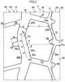
Fig. 2 is a partial, enlarged plan view ofFig. 1 . -
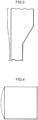
Fig. 3 is a plan view for explaining the deformed state of a block that does not have a vertex at the left side. -
Fig. 4 is a plan view for explaining the deformed state of a rectangular block that has a vertex at the left side. - Embodiment 1 of the invention is described hereinafter on the basis of the drawings. In
Figs. 1 and2 , 11 is a normal pneumatic tire that is mounted to a passenger vehicle, a truck/bus or the like. Thistire 11 has atread 12 that is formed from a vulcanized rubber and contacts the road surface at the radial direction outer end thereof. A centralnarrow groove 13, which extends continuously along tire equator S without interruption in the tire circumferential direction, is formed in the tread central portion which includes the tire equator S of thetread 12. This centralnarrow groove 13 is bent in a zigzag shape (a triangular wave shape) whose amplitude from the tire equator S is the same. Further, due to block land portions, which are described later and are positioned at both sides of this centralnarrow groove 13 collapsing-deforming due to the load applied at the time of ground contact when the centralnarrow groove 13 intrudes into the ground-contact region, the side walls thereof (the inner-side side walls in the tire axial direction of the central narrow groove 13) contact one another. Due thereto, the force of collapsing-deforming the block land portions that are adjacent in the tire width direction is transmitted effectively. Here, in order to cause collapsing deformation such as described above at the block land portions, the groove width of the centralnarrow groove 13 is preferably set within a range of 1.0 to 5.0 mm, and is more preferably set within a range of 1.5 to 3.5 mm. - Two central
circumferential grooves narrow groove 13. These two centralcircumferential grooves narrow groove 13. From the standpoint of suppressing a deterioration in the wear resistance and the on-snow performance, the groove widths of these centralcircumferential grooves narrow groove 13, and are preferably set to within a range of 3.0 to 10.0 mm, and more preferably set within a range of 4.0 to 8.0 mm. These centralcircumferential grooves narrow groove 13 may be disposed so as to be offset by about 1/3 of a pitch in the tire circumferential direction. Plurallateral grooves 19 that extend in the tire width direction are formed in acentral land portion 18 that is demarcated between the centralnarrow groove 13 and the centralcircumferential groove 16 and that extends in the tire circumferential direction. Further, plurallateral grooves 21 that extend in the tire width direction are formed in acentral land portion 20 that is demarcated between the centralnarrow groove 13 and the centralcircumferential groove 17 and that extends in the tire circumferential direction. Due thereto, the centralnarrow groove 13 and the centralcircumferential grooves lateral grooves - These
lateral grooves lateral grooves 19 open at the largest amplitude portions that veer toward the centralcircumferential groove 16 side of the centralnarrow groove 13. Further, the tire width direction outer ends of thelateral grooves 19 open at the largest amplitude portions that veer toward the centralnarrow groove 13 side of the centralcircumferential groove 16. On the other hand, the tire width direction inner ends of thelateral grooves 21 open at the largest amplitude portions that veer toward the centralcircumferential groove 17 side of the centralnarrow groove 13. Further, the tire width direction outer ends of thelateral grooves 21 open at the largest amplitude portions that veer toward the centralnarrow groove 13 side of the centralcircumferential groove 17. If, in this way, the one centralnarrow groove 13 is formed in thetread 12, and the two centralcircumferential grooves narrow groove 13, and, on the other hand, the plurallateral grooves 19 that communicate the centralnarrow groove 13 and the centralcircumferential groove 16 and the plurallateral grooves 21 that communicate the centralnarrow groove 13 and the centralcircumferential groove 17 are formed in thecentral land portions narrow groove 13 and the centralcircumferential grooves block land portions central land portions narrow groove 13 and centralcircumferential grooves lateral grooves block land portions side walls lateral grooves block land portions - The above-described numerous
block land portions 22 that assume hexagonal shapes, on the whole, structure a blockland portion row 24 that is sectioned and formed between the centralnarrow groove 13 and the centralcircumferential groove 16. Further, theblock land portions 23 on the whole structure a blockland portion row 25 that is sectioned and formed between the centralnarrow groove 13 and the centralcircumferential groove 17. Note that, in this embodiment, the numerousblock land portions circumferential grooves Inner side cutouts 28, which extend rectilinearly toward outer-side side walls 22b in the tire width direction of theblock land portions 22, are formed in the inner-side side walls 22a in the tire width direction, which are exposed to the centralnarrow groove 13, of the respectiveblock land portions 22, at the tire circumferential central portions thereof, and here, in vicinities of the vertices where the inner-side side walls 22a intersect at obtuse angles, in order to improve the drainage characteristics while suppressing a deterioration in the wear resistance. Further,inner side cutouts 29, which extend rectilinearly toward outer-side side walls 23b in the tire width direction of theblock land portions 23, are formed in inner-side side walls 23a in the tire width direction, which are exposed to the centralnarrow groove 13, of the respectiveblock land portions 23, at the tire circumferential central portions thereof, and here, in vicinities of the vertices where the inner-side side walls 23a intersect at obtuse angles, in order to improve the drainage characteristics while suppressing a deterioration in the wear resistance. - Further, a decrease in the rigidity at the
block land portions inner side cutouts block land portions circumferential grooves block land portions 22, 23 (the distance from the inner-side side wall 22a to the outer-side side wall 22b, and the distance from the inner-side side wall 23a to the outer-side side wall 23b, measured along a straight line that is orthogonal to the tire equator S) respectively are relatively small values at the positions of theinner side cutouts inner side cutouts side side walls block land portions wall portions wall portions wall portions wall portions wall portions block land portions - Outer side
circumferential grooves circumferential grooves circumferential grooves side land portions 34 and first outerside land portions 36, which serve as outer side land portions and extend in the tire circumferential direction, are respectively provided further toward the tire width direction outer sides than the two centralcircumferential grooves circumferential groove 16 and the outer sidecircumferential groove 32, and between the centralcircumferential groove 17 and the outer sidecircumferential groove 33. Plurallateral grooves side land portions circumferential groove 16 and the outer sidecircumferential groove 32 are communicated with one another by thelateral grooves 35. Further, the centralcircumferential groove 17 and the outer sidecircumferential groove 33 are communicated with one another by thelateral grooves 37. Further, thelateral grooves lateral grooves side land portions circumferential grooves circumferential grooves lateral grooves side block rows circumferential groove 16 and the outer sidecircumferential groove 32, and between the centralcircumferential groove 17 and the outer sidecircumferential groove 33, respectively. - Second outer
side land portions circumferential grooves lateral grooves side land portions lateral grooves circumferential grooves lateral grooves lateral grooves side land portions circumferential grooves lateral grooves side block rows circumferential groove 32 and the tread end D, and between the outer sidecircumferential groove 33 and the tread end D, respectively. - Here, plural
outer side cutouts block land portions circumferential grooves side land portions side side walls outer side cutouts side land portions 34, 36 (the first outer side blocks 38, 39) without reaching the outer sidecircumferential grooves side land portions - Further, in this embodiment, the
outer side cutouts tire 11. Namely, as described above, the respectiveblock land portions side walls lateral grooves block land portions inner side cutouts side side walls side side walls block land portions inner side cutouts block land portions block land portions inner side cutouts inner side cutouts 28, 29 (at one place or at two places). Here, the maximum width position that is at the tire circumferential direction one side where the tire circumferential direction length is long, i.e., at the long side-wall portions block land portion block land portion - Further, when the
block land portions tire 11, theblock land portions block land portions side land portions 34, 36). Here, because deformation toward the tire width direction outer side is important as will be described later, with regard to the expansion deformation of theblock land portions side side walls block land portions Fig. 3 , the greater the width direction distance, the greater the amount of the expansion deformation, as shown by the imaginary line. Therefore, the amount of expansion of theblock land portion 22, 23 (the outer-side side wall block land portion tire 11 traveling on a road surface that is covered by some accumulated snow, the snow that is pushed into the centralcircumferential grooves tire 11 is pushed out toward the first outerside land portions side side walls - On the other hand, consideration is given as to how the outer-
side side walls block land portion Fig. 4 , the greater the distance from the vertex of the outer-side side wall, the more the amount of expansion deformation increases as shown by the imaginary line. Therefore, the amount of expansion deformation toward the tire width direction outer side of theblock land portion 22, 23 (the outer-side side wall block land portions - Here, in this embodiment, the maximum width position, which is positioned further toward a tire circumferential direction one side than the
inner side cutout wall portion block land portion inner side cutout inner side cutout wall portion block land portion tire 11 traveling on a road surface that is covered by some accumulated snow, the snow that is pushed into the centralcircumferential grooves tire 11 is pushed out toward the first outerside land portions side side walls - Further, the amount of expansion deformation of the
block land portion outer side cutouts side land portions 34, 36 (the first outer side blocks 38, 39), and, moreover, at least portions of tire width directioninner side openings outer side cutouts block land portion - Due thereto, due to the snow that is pushed into the central
circumferential grooves outer side cutouts block land portions outer side cutouts outer side cutouts side land portions 34, 36 (the first outer side blocks 38, 39) also are crushed in the radial direction, but, at this time, the facing side walls of theouter side cutouts outer side cutouts outer side cutouts tire 11 as a large gripping force, and the on-snow performance of thetire 11 can easily be improved. Here, the greater the amount of overlap between the region G and the tire width directioninner side opening outer side cutout side side walls block land portions 22, 23) contacting one another within the ground-contact region, the above-described expansion deformation of theblock land portions 22, 23 (the outer-side side walls circumferential grooves 16, 17) is limited, and therefore becomes a large value. As a result, even more of the snow, which has been pushed into the centralcircumferential grooves side land portions block land portions - When the respective
block land portions wall portion wall portion wall portion block land portion side side wall outer side cutouts inner side cutouts side side walls block land portions - Further, in this embodiment, the two regions, which are positioned at both the tire circumferential direction sides of the
outer side cutouts side side walls side land portions 34, 36 (the first outer side blocks 38, 39), are made to intersect at intersection angle J that is greater than 90° and less than 180°, i.e., at an obtuse angle. By doing so, the snow, which has been pushed against the peripheries of theouter side cutouts outer side cutouts side side walls side land portions 34, 36 (the first outer side blocks 38, 39) that assume parabolic shapes. Due thereto, highly-dense snow columns can be formed easily. Further, length M of theouter side cutouts circumferential grooves outer side cutouts outer side cutouts - Moreover, in the present embodiment, groove width central line Q of the
outer side cutouts side side wall block land portion wall portion block land portions outer side cutouts outer side cutouts block land portion Fig. 2 , in order to make the flow of water in the centralcircumferential grooves - The present invention can be applied to the industrial field of tires in which block land portion rows, which are formed from numerous block land portions, are disposed at the tread central portion.
Claims (4)
- A tire (11) in which, by forming a central narrow groove (13), which is formed in a tread central portion and extends in a tire circumferential direction while having a zigzag shape, and two central circumferential grooves (16, 17), which are respectively formed at both tire width direction outer sides of the central narrow groove (13) and extend in the tire circumferential direction and have widths that are wider than the central narrow groove (13), and a plurality of lateral grooves (19, 21), which communicate the central narrow groove (13) with the central circumferential grooves (16, 17) and extend in a tire width direction and are spaced apart in the tire circumferential direction, two block land portion rows (24, 25) are sectioned and formed between the central narrow groove (13) and the central circumferential grooves (16, 17) respectively, and each block land portion row (24, 25) is structured from numerous block land portions (22, 23) having tire circumferential direction side walls that are side walls (19a, 21a) of the lateral grooves (19, 21), wherein:a plurality of outer side cutouts (54, 55), which respectively correspond to the block land portions (22, 23) and extend toward tire width direction outer sides and end midway along outer side land portions (34, 36), are spaced apart in the tire circumferential direction in tire width direction inner-side side walls (38a, 39a), which are exposed to the central circumferential grooves (16, 17), of the outer side land portions (34, 36) that are provided further toward tire width direction outer sides than the two central circumferential grooves (16, 17) respectively, characterized in thatat least portions of tire width direction inner side openings (54a, 55a) of the outer side cutouts (54, 55) are positioned between maximum position A, at which a tire width direction distance of a corresponding block land portion (22, 23) is a maximum, and an intermediate point B of two vertices (Pa, Pb) that are adjacent at a tire width direction outer-side side wall (22b, 23b) of the block land portion (22, 23),due to the central circumferential grooves (16, 17) being formed in zigzag shapes, the respective block land portions (22, 23) are hexagonal, and a tire width direction outer-side side wall (22b, 23b) of the block land portion (22, 23) is structured from one long side-wall portion (22c, 23c) and one short side-wall portion (22d, 23d) having a circumferential direction length that is shorter than the long side-wall portion (22c, 23c), and one (Pa) of the two vertices (Pa, Pb) is structured from a point of intersection of the long side-wall portion (22c, 23c) and the short side-wall portion (22d, 23d), and another of the two vertices (Pb) is structured from a point of intersection of the long side-wall portion (22c, 23c) and a tire circumferential direction side wall of the block land portion (22, 23), andthe intermediate point B is positioned at the long side-wall portion (22c, 23c).
- The tire (11) of claim 1, wherein regions, which are positioned at both tire circumferential direction sides of the outer side cutout (54, 55) at a tire width direction inner-side side wall (38a, 39a) of the outer side land portion (34, 36), intersect at an obtuse angle.
- The tire (11) of claim 1 or 2, wherein a length of the outer side cutout (54, 55) is shorter than a width of the central circumferential grooves (16, 17).
- The tire (11) of any one of claims 1 through 3, wherein a groove width central line (Q) of the outer side cutout (54, 55) intersects a tire width direction outer-side side wall (22b, 23b) of the block land portion (22, 23) at a right angle or at an angle that approximates a right angle.
Applications Claiming Priority (2)
| Application Number | Priority Date | Filing Date | Title |
|---|---|---|---|
| JP2017200582A JP6925227B2 (en) | 2017-10-16 | 2017-10-16 | tire |
| PCT/JP2018/033253 WO2019077905A1 (en) | 2017-10-16 | 2018-09-07 | tire |
Publications (3)
| Publication Number | Publication Date |
|---|---|
| EP3698983A1 EP3698983A1 (en) | 2020-08-26 |
| EP3698983A4 EP3698983A4 (en) | 2021-06-16 |
| EP3698983B1 true EP3698983B1 (en) | 2023-03-15 |
Family
ID=66174372
Family Applications (1)
| Application Number | Title | Priority Date | Filing Date |
|---|---|---|---|
| EP18867986.4A Active EP3698983B1 (en) | 2017-10-16 | 2018-09-07 | Tire |
Country Status (5)
| Country | Link |
|---|---|
| US (1) | US11453246B2 (en) |
| EP (1) | EP3698983B1 (en) |
| JP (1) | JP6925227B2 (en) |
| CN (1) | CN111212747B (en) |
| WO (1) | WO2019077905A1 (en) |
Families Citing this family (2)
| Publication number | Priority date | Publication date | Assignee | Title |
|---|---|---|---|---|
| JP7399679B2 (en) * | 2019-10-29 | 2023-12-18 | 株式会社ブリヂストン | pneumatic tires |
| TWI803826B (en) * | 2021-02-09 | 2023-06-01 | 正新橡膠工業股份有限公司 | Tire tread noise reduction structure |
Family Cites Families (38)
| Publication number | Priority date | Publication date | Assignee | Title |
|---|---|---|---|---|
| JPS62120203A (en) * | 1985-11-20 | 1987-06-01 | Bridgestone Corp | Pneumatic tire |
| JP2659705B2 (en) | 1986-04-24 | 1997-09-30 | 株式会社ブリヂストン | Pneumatic tire with excellent traction and braking performance |
| JP2890020B2 (en) | 1995-08-31 | 1999-05-10 | 東洋ゴム工業株式会社 | Pneumatic tire |
| JP4149552B2 (en) | 1998-03-06 | 2008-09-10 | 住友ゴム工業株式会社 | Radial tires for running in snowy muddy ground |
| JP2000025420A (en) | 1998-07-14 | 2000-01-25 | Yokohama Rubber Co Ltd:The | Pneumatic radial tire for small-sized truck |
| JP4262813B2 (en) | 1998-12-18 | 2009-05-13 | 横浜ゴム株式会社 | studless tire |
| JP4256004B2 (en) | 1999-02-01 | 2009-04-22 | 株式会社ブリヂストン | Pneumatic tire |
| JP2001191739A (en) | 2000-01-13 | 2001-07-17 | Bridgestone Corp | Pneumatic tire |
| JP4138688B2 (en) | 2004-03-25 | 2008-08-27 | 住友ゴム工業株式会社 | Pneumatic tire |
| JP2006335232A (en) * | 2005-06-02 | 2006-12-14 | Sumitomo Rubber Ind Ltd | Heavy duty tire |
| JP4377862B2 (en) * | 2005-08-04 | 2009-12-02 | 住友ゴム工業株式会社 | Heavy duty pneumatic tire |
| JP2007099110A (en) | 2005-10-05 | 2007-04-19 | Toyo Tire & Rubber Co Ltd | Pneumatic tire |
| JP4921889B2 (en) | 2006-08-23 | 2012-04-25 | 住友ゴム工業株式会社 | Pneumatic tire |
| JP4942167B2 (en) * | 2006-08-31 | 2012-05-30 | 東洋ゴム工業株式会社 | Pneumatic tire |
| JP4938387B2 (en) | 2006-08-31 | 2012-05-23 | 東洋ゴム工業株式会社 | Pneumatic tire |
| JP5039377B2 (en) | 2006-12-26 | 2012-10-03 | 株式会社ブリヂストン | Pneumatic tire |
| CN105128602B (en) | 2007-05-28 | 2020-06-19 | 株式会社普利司通 | Tyre for vehicle wheels |
| WO2009084666A1 (en) * | 2007-12-28 | 2009-07-09 | Bridgestone Corporation | Tire |
| JP2010047140A (en) * | 2008-08-22 | 2010-03-04 | Bridgestone Corp | Tire |
| JP5291107B2 (en) | 2008-08-22 | 2013-09-18 | 株式会社ブリヂストン | tire |
| IT1396282B1 (en) | 2009-09-22 | 2012-11-16 | Bridgestone Corp | WINTER TIRE WITH INCREASED TRACTION CAPACITY ON SNOW COVERS. |
| JP5506462B2 (en) * | 2010-03-08 | 2014-05-28 | 株式会社ブリヂストン | Pneumatic tire |
| JP5675228B2 (en) * | 2010-09-01 | 2015-02-25 | 株式会社ブリヂストン | tire |
| US20140238568A1 (en) * | 2011-10-03 | 2014-08-28 | Bridgestone Corporation | Pneumatic tire for heavy load |
| JP6169326B2 (en) | 2012-05-28 | 2017-07-26 | 株式会社ブリヂストン | Pneumatic tire |
| JP5898646B2 (en) | 2013-02-15 | 2016-04-06 | 住友ゴム工業株式会社 | Pneumatic tire |
| US9757991B2 (en) | 2013-02-19 | 2017-09-12 | Sumitomo Rubber Industries, Ltd. | Pneumatic tire |
| JP5913201B2 (en) | 2013-05-14 | 2016-04-27 | 住友ゴム工業株式会社 | Pneumatic tire |
| RU2599856C1 (en) * | 2013-03-06 | 2016-10-20 | Дзе Йокогама Раббер Ко., Лтд. | Pneumatic tyre |
| JP6258785B2 (en) | 2013-06-10 | 2018-01-10 | 東洋ゴム工業株式会社 | Pneumatic tire |
| JP5941449B2 (en) | 2013-09-24 | 2016-06-29 | 住友ゴム工業株式会社 | Pneumatic tire |
| JP6027576B2 (en) | 2014-07-07 | 2016-11-16 | 住友ゴム工業株式会社 | Pneumatic tire |
| JP6154834B2 (en) * | 2015-01-07 | 2017-06-28 | 住友ゴム工業株式会社 | Pneumatic tire |
| JP6514591B2 (en) | 2015-07-09 | 2019-05-15 | 住友ゴム工業株式会社 | Heavy duty pneumatic tire |
| DE102015221257A1 (en) * | 2015-10-30 | 2017-05-04 | Continental Reifen Deutschland Gmbh | Vehicle tires |
| US10368898B2 (en) | 2016-05-05 | 2019-08-06 | Covidien Lp | Ultrasonic surgical instrument |
| JP6676485B2 (en) * | 2016-06-30 | 2020-04-08 | Toyo Tire株式会社 | Pneumatic tire |
| CN107031304A (en) * | 2017-04-27 | 2017-08-11 | 杭州朝阳橡胶有限公司 | A kind of snowfield tugboat tire for being applied to wide base truck |
-
2017
- 2017-10-16 JP JP2017200582A patent/JP6925227B2/en active Active
-
2018
- 2018-09-07 CN CN201880066641.3A patent/CN111212747B/en active Active
- 2018-09-07 EP EP18867986.4A patent/EP3698983B1/en active Active
- 2018-09-07 WO PCT/JP2018/033253 patent/WO2019077905A1/en not_active Ceased
- 2018-09-07 US US16/756,125 patent/US11453246B2/en active Active
Also Published As
| Publication number | Publication date |
|---|---|
| JP2019073162A (en) | 2019-05-16 |
| CN111212747A (en) | 2020-05-29 |
| EP3698983A1 (en) | 2020-08-26 |
| EP3698983A4 (en) | 2021-06-16 |
| US20200238767A1 (en) | 2020-07-30 |
| WO2019077905A1 (en) | 2019-04-25 |
| JP6925227B2 (en) | 2021-08-25 |
| US11453246B2 (en) | 2022-09-27 |
| CN111212747B (en) | 2022-06-28 |
Similar Documents
| Publication | Publication Date | Title |
|---|---|---|
| CN106042785B (en) | Pneumatic tire | |
| KR101576303B1 (en) | Pneumatic tire | |
| JP4510903B2 (en) | Pneumatic tire | |
| US20160368326A1 (en) | Pneumatic tire | |
| RU2657616C2 (en) | Pneumatic tyre | |
| CN108725101B (en) | Tyre for vehicle wheels | |
| CN204398765U (en) | Air-inflation tyre | |
| CN108367623B (en) | Vehicle Pneumatic Tires | |
| CN103228466A (en) | Pneumatic tyre for a vehicle | |
| US20170157989A1 (en) | Incised tread for civil engineering tire | |
| JP2017226368A (en) | Pneumatic tire | |
| WO2017187740A1 (en) | Pneumatic tire | |
| US10576791B2 (en) | Tire | |
| JP2018177094A (en) | tire | |
| EP3698983B1 (en) | Tire | |
| US9254720B2 (en) | Pneumatic tire for construction vehicle | |
| JP6579895B2 (en) | Pneumatic tire | |
| US8245744B2 (en) | Tire with tread having Z-shaped sipes in circumferential rib | |
| JP5698622B2 (en) | tire | |
| CN102232026B (en) | Vehicle Pneumatic Tires | |
| JP5533239B2 (en) | Pneumatic tire | |
| JP2011088544A (en) | Tire | |
| JP6748413B2 (en) | Pneumatic tire | |
| JP2001213120A (en) | Pneumatic tire | |
| CN105980172B (en) | Vehicle Pneumatic Tires |
Legal Events
| Date | Code | Title | Description |
|---|---|---|---|
| STAA | Information on the status of an ep patent application or granted ep patent |
Free format text: STATUS: THE INTERNATIONAL PUBLICATION HAS BEEN MADE |
|
| PUAI | Public reference made under article 153(3) epc to a published international application that has entered the european phase |
Free format text: ORIGINAL CODE: 0009012 |
|
| STAA | Information on the status of an ep patent application or granted ep patent |
Free format text: STATUS: REQUEST FOR EXAMINATION WAS MADE |
|
| 17P | Request for examination filed |
Effective date: 20200415 |
|
| AK | Designated contracting states |
Kind code of ref document: A1 Designated state(s): AL AT BE BG CH CY CZ DE DK EE ES FI FR GB GR HR HU IE IS IT LI LT LU LV MC MK MT NL NO PL PT RO RS SE SI SK SM TR |
|
| AX | Request for extension of the european patent |
Extension state: BA ME |
|
| DAV | Request for validation of the european patent (deleted) | ||
| DAX | Request for extension of the european patent (deleted) | ||
| A4 | Supplementary search report drawn up and despatched |
Effective date: 20210518 |
|
| RIC1 | Information provided on ipc code assigned before grant |
Ipc: B60C 11/03 20060101AFI20210511BHEP |
|
| GRAP | Despatch of communication of intention to grant a patent |
Free format text: ORIGINAL CODE: EPIDOSNIGR1 |
|
| STAA | Information on the status of an ep patent application or granted ep patent |
Free format text: STATUS: GRANT OF PATENT IS INTENDED |
|
| INTG | Intention to grant announced |
Effective date: 20221025 |
|
| RIN1 | Information on inventor provided before grant (corrected) |
Inventor name: NAGAMOTO, SHOKO Inventor name: TAKEI, ATAKA Inventor name: WATANABE, ATSUSHI |
|
| GRAS | Grant fee paid |
Free format text: ORIGINAL CODE: EPIDOSNIGR3 |
|
| GRAA | (expected) grant |
Free format text: ORIGINAL CODE: 0009210 |
|
| STAA | Information on the status of an ep patent application or granted ep patent |
Free format text: STATUS: THE PATENT HAS BEEN GRANTED |
|
| AK | Designated contracting states |
Kind code of ref document: B1 Designated state(s): AL AT BE BG CH CY CZ DE DK EE ES FI FR GB GR HR HU IE IS IT LI LT LU LV MC MK MT NL NO PL PT RO RS SE SI SK SM TR |
|
| REG | Reference to a national code |
Ref country code: CH Ref legal event code: EP Ref country code: GB Ref legal event code: FG4D |
|
| REG | Reference to a national code |
Ref country code: DE Ref legal event code: R096 Ref document number: 602018047334 Country of ref document: DE |
|
| REG | Reference to a national code |
Ref country code: IE Ref legal event code: FG4D |
|
| REG | Reference to a national code |
Ref country code: AT Ref legal event code: REF Ref document number: 1553799 Country of ref document: AT Kind code of ref document: T Effective date: 20230415 |
|
| REG | Reference to a national code |
Ref country code: LT Ref legal event code: MG9D |
|
| REG | Reference to a national code |
Ref country code: NL Ref legal event code: MP Effective date: 20230315 |
|
| PG25 | Lapsed in a contracting state [announced via postgrant information from national office to epo] |
Ref country code: RS Free format text: LAPSE BECAUSE OF FAILURE TO SUBMIT A TRANSLATION OF THE DESCRIPTION OR TO PAY THE FEE WITHIN THE PRESCRIBED TIME-LIMIT Effective date: 20230315 Ref country code: NO Free format text: LAPSE BECAUSE OF FAILURE TO SUBMIT A TRANSLATION OF THE DESCRIPTION OR TO PAY THE FEE WITHIN THE PRESCRIBED TIME-LIMIT Effective date: 20230615 Ref country code: LV Free format text: LAPSE BECAUSE OF FAILURE TO SUBMIT A TRANSLATION OF THE DESCRIPTION OR TO PAY THE FEE WITHIN THE PRESCRIBED TIME-LIMIT Effective date: 20230315 Ref country code: LT Free format text: LAPSE BECAUSE OF FAILURE TO SUBMIT A TRANSLATION OF THE DESCRIPTION OR TO PAY THE FEE WITHIN THE PRESCRIBED TIME-LIMIT Effective date: 20230315 Ref country code: HR Free format text: LAPSE BECAUSE OF FAILURE TO SUBMIT A TRANSLATION OF THE DESCRIPTION OR TO PAY THE FEE WITHIN THE PRESCRIBED TIME-LIMIT Effective date: 20230315 |
|
| REG | Reference to a national code |
Ref country code: AT Ref legal event code: MK05 Ref document number: 1553799 Country of ref document: AT Kind code of ref document: T Effective date: 20230315 |
|
| PG25 | Lapsed in a contracting state [announced via postgrant information from national office to epo] |
Ref country code: SE Free format text: LAPSE BECAUSE OF FAILURE TO SUBMIT A TRANSLATION OF THE DESCRIPTION OR TO PAY THE FEE WITHIN THE PRESCRIBED TIME-LIMIT Effective date: 20230315 Ref country code: NL Free format text: LAPSE BECAUSE OF FAILURE TO SUBMIT A TRANSLATION OF THE DESCRIPTION OR TO PAY THE FEE WITHIN THE PRESCRIBED TIME-LIMIT Effective date: 20230315 Ref country code: GR Free format text: LAPSE BECAUSE OF FAILURE TO SUBMIT A TRANSLATION OF THE DESCRIPTION OR TO PAY THE FEE WITHIN THE PRESCRIBED TIME-LIMIT Effective date: 20230616 Ref country code: FI Free format text: LAPSE BECAUSE OF FAILURE TO SUBMIT A TRANSLATION OF THE DESCRIPTION OR TO PAY THE FEE WITHIN THE PRESCRIBED TIME-LIMIT Effective date: 20230315 |
|
| PG25 | Lapsed in a contracting state [announced via postgrant information from national office to epo] |
Ref country code: SM Free format text: LAPSE BECAUSE OF FAILURE TO SUBMIT A TRANSLATION OF THE DESCRIPTION OR TO PAY THE FEE WITHIN THE PRESCRIBED TIME-LIMIT Effective date: 20230315 Ref country code: RO Free format text: LAPSE BECAUSE OF FAILURE TO SUBMIT A TRANSLATION OF THE DESCRIPTION OR TO PAY THE FEE WITHIN THE PRESCRIBED TIME-LIMIT Effective date: 20230315 Ref country code: PT Free format text: LAPSE BECAUSE OF FAILURE TO SUBMIT A TRANSLATION OF THE DESCRIPTION OR TO PAY THE FEE WITHIN THE PRESCRIBED TIME-LIMIT Effective date: 20230717 Ref country code: ES Free format text: LAPSE BECAUSE OF FAILURE TO SUBMIT A TRANSLATION OF THE DESCRIPTION OR TO PAY THE FEE WITHIN THE PRESCRIBED TIME-LIMIT Effective date: 20230315 Ref country code: EE Free format text: LAPSE BECAUSE OF FAILURE TO SUBMIT A TRANSLATION OF THE DESCRIPTION OR TO PAY THE FEE WITHIN THE PRESCRIBED TIME-LIMIT Effective date: 20230315 Ref country code: CZ Free format text: LAPSE BECAUSE OF FAILURE TO SUBMIT A TRANSLATION OF THE DESCRIPTION OR TO PAY THE FEE WITHIN THE PRESCRIBED TIME-LIMIT Effective date: 20230315 Ref country code: AT Free format text: LAPSE BECAUSE OF FAILURE TO SUBMIT A TRANSLATION OF THE DESCRIPTION OR TO PAY THE FEE WITHIN THE PRESCRIBED TIME-LIMIT Effective date: 20230315 |
|
| PG25 | Lapsed in a contracting state [announced via postgrant information from national office to epo] |
Ref country code: SK Free format text: LAPSE BECAUSE OF FAILURE TO SUBMIT A TRANSLATION OF THE DESCRIPTION OR TO PAY THE FEE WITHIN THE PRESCRIBED TIME-LIMIT Effective date: 20230315 Ref country code: PL Free format text: LAPSE BECAUSE OF FAILURE TO SUBMIT A TRANSLATION OF THE DESCRIPTION OR TO PAY THE FEE WITHIN THE PRESCRIBED TIME-LIMIT Effective date: 20230315 Ref country code: IS Free format text: LAPSE BECAUSE OF FAILURE TO SUBMIT A TRANSLATION OF THE DESCRIPTION OR TO PAY THE FEE WITHIN THE PRESCRIBED TIME-LIMIT Effective date: 20230715 |
|
| REG | Reference to a national code |
Ref country code: DE Ref legal event code: R097 Ref document number: 602018047334 Country of ref document: DE |
|
| PLBE | No opposition filed within time limit |
Free format text: ORIGINAL CODE: 0009261 |
|
| STAA | Information on the status of an ep patent application or granted ep patent |
Free format text: STATUS: NO OPPOSITION FILED WITHIN TIME LIMIT |
|
| PG25 | Lapsed in a contracting state [announced via postgrant information from national office to epo] |
Ref country code: SI Free format text: LAPSE BECAUSE OF FAILURE TO SUBMIT A TRANSLATION OF THE DESCRIPTION OR TO PAY THE FEE WITHIN THE PRESCRIBED TIME-LIMIT Effective date: 20230315 Ref country code: DK Free format text: LAPSE BECAUSE OF FAILURE TO SUBMIT A TRANSLATION OF THE DESCRIPTION OR TO PAY THE FEE WITHIN THE PRESCRIBED TIME-LIMIT Effective date: 20230315 |
|
| 26N | No opposition filed |
Effective date: 20231218 |
|
| REG | Reference to a national code |
Ref country code: CH Ref legal event code: PL |
|
| PG25 | Lapsed in a contracting state [announced via postgrant information from national office to epo] |
Ref country code: LU Free format text: LAPSE BECAUSE OF NON-PAYMENT OF DUE FEES Effective date: 20230907 |
|
| REG | Reference to a national code |
Ref country code: BE Ref legal event code: MM Effective date: 20230930 |
|
| GBPC | Gb: european patent ceased through non-payment of renewal fee |
Effective date: 20230907 |
|
| PG25 | Lapsed in a contracting state [announced via postgrant information from national office to epo] |
Ref country code: LU Free format text: LAPSE BECAUSE OF NON-PAYMENT OF DUE FEES Effective date: 20230907 Ref country code: IT Free format text: LAPSE BECAUSE OF FAILURE TO SUBMIT A TRANSLATION OF THE DESCRIPTION OR TO PAY THE FEE WITHIN THE PRESCRIBED TIME-LIMIT Effective date: 20230315 Ref country code: MC Free format text: LAPSE BECAUSE OF FAILURE TO SUBMIT A TRANSLATION OF THE DESCRIPTION OR TO PAY THE FEE WITHIN THE PRESCRIBED TIME-LIMIT Effective date: 20230315 |
|
| REG | Reference to a national code |
Ref country code: IE Ref legal event code: MM4A |
|
| PG25 | Lapsed in a contracting state [announced via postgrant information from national office to epo] |
Ref country code: IE Free format text: LAPSE BECAUSE OF NON-PAYMENT OF DUE FEES Effective date: 20230907 |
|
| PG25 | Lapsed in a contracting state [announced via postgrant information from national office to epo] |
Ref country code: GB Free format text: LAPSE BECAUSE OF NON-PAYMENT OF DUE FEES Effective date: 20230907 |
|
| PG25 | Lapsed in a contracting state [announced via postgrant information from national office to epo] |
Ref country code: CH Free format text: LAPSE BECAUSE OF NON-PAYMENT OF DUE FEES Effective date: 20230930 |
|
| PG25 | Lapsed in a contracting state [announced via postgrant information from national office to epo] |
Ref country code: IE Free format text: LAPSE BECAUSE OF NON-PAYMENT OF DUE FEES Effective date: 20230907 Ref country code: GB Free format text: LAPSE BECAUSE OF NON-PAYMENT OF DUE FEES Effective date: 20230907 Ref country code: CH Free format text: LAPSE BECAUSE OF NON-PAYMENT OF DUE FEES Effective date: 20230930 |
|
| PG25 | Lapsed in a contracting state [announced via postgrant information from national office to epo] |
Ref country code: BE Free format text: LAPSE BECAUSE OF NON-PAYMENT OF DUE FEES Effective date: 20230930 |
|
| PG25 | Lapsed in a contracting state [announced via postgrant information from national office to epo] |
Ref country code: BG Free format text: LAPSE BECAUSE OF FAILURE TO SUBMIT A TRANSLATION OF THE DESCRIPTION OR TO PAY THE FEE WITHIN THE PRESCRIBED TIME-LIMIT Effective date: 20230315 |
|
| P01 | Opt-out of the competence of the unified patent court (upc) registered |
Free format text: CASE NUMBER: APP_57154/2024 Effective date: 20241018 |
|
| PG25 | Lapsed in a contracting state [announced via postgrant information from national office to epo] |
Ref country code: BG Free format text: LAPSE BECAUSE OF FAILURE TO SUBMIT A TRANSLATION OF THE DESCRIPTION OR TO PAY THE FEE WITHIN THE PRESCRIBED TIME-LIMIT Effective date: 20230315 |
|
| PG25 | Lapsed in a contracting state [announced via postgrant information from national office to epo] |
Ref country code: CY Free format text: LAPSE BECAUSE OF FAILURE TO SUBMIT A TRANSLATION OF THE DESCRIPTION OR TO PAY THE FEE WITHIN THE PRESCRIBED TIME-LIMIT; INVALID AB INITIO Effective date: 20180907 |
|
| PG25 | Lapsed in a contracting state [announced via postgrant information from national office to epo] |
Ref country code: HU Free format text: LAPSE BECAUSE OF FAILURE TO SUBMIT A TRANSLATION OF THE DESCRIPTION OR TO PAY THE FEE WITHIN THE PRESCRIBED TIME-LIMIT; INVALID AB INITIO Effective date: 20180907 |
|
| PGFP | Annual fee paid to national office [announced via postgrant information from national office to epo] |
Ref country code: DE Payment date: 20250919 Year of fee payment: 8 |
|
| PGFP | Annual fee paid to national office [announced via postgrant information from national office to epo] |
Ref country code: FR Payment date: 20250922 Year of fee payment: 8 |
|
| PG25 | Lapsed in a contracting state [announced via postgrant information from national office to epo] |
Ref country code: TR Free format text: LAPSE BECAUSE OF FAILURE TO SUBMIT A TRANSLATION OF THE DESCRIPTION OR TO PAY THE FEE WITHIN THE PRESCRIBED TIME-LIMIT Effective date: 20230315 |